 Open Access Article
Magnetically controlled bio-inspired elastomeric actuators with high mechanical energy storage
Mohammadreza
Lalegani Dezaki
 and
Mahdi
Bodaghi
 *
*
Department of Engineering, School of Science and Technology, Nottingham Trent University, Nottingham, NG11 8NS, UK. E-mail: mahdi.bodaghi@ntu.ac.uk
First published on 31st March 2023
Abstract
Many biological systems are made to operate more quickly, efficiently, and with more power by storing elastic energy. This work introduces a straightforward bioinspired design for the quick manufacture of pre-stressed soft magnetic actuators. The actuator requires a lower magnetic field strength to be activated and can regain its original shape without the need for external stimuli. These characteristics are demonstrated in this work through the creation of actuators with round and helical shape structures inspired by the tendril plant and chameleon's tongue. Both the final form of the actuator and its actuation sequence may be programmed by controlling the direction and strength of the force utilised to pre-stress the elastomeric layer. Analytical models are presented to trace the actuators' energy storage, radius, and pitch. High-speed shape recovery after releasing the magnetic force and a strong grasping force are achieved due to the stored mechanical elastic energy. Experiments are conducted to analyse the shape changes, grasping action, and determine the actuation force. The manufacture of the grippers with zero-magnetic field strength holding capacities of up to 20 times their weight is made possible by the elastic energy that actuators store in their pre-stressed elastomeric layer. The outcomes of our research show that a unique magnetic field-controlled soft actuator can be created in different shapes and designs based on requirements.
1. Introduction
The remarkable animal abilities—from muscular contraction and relaxation to mobility—have served as inspiration for soft robotics.1,2 Strain energy storage in musculoskeletal and tendon tissues is an essential element of animal locomotor systems.3 The creation of robotic structures that take advantage of the elastic energy stored in their elastic and rigid/semirigid components to produce quick motion and improve their performance has been motivated by nature.4–6 The implementation of these bio-inspired methods for storing elastic energy in robots lacking solid structural components is challenging, which limits the use of these techniques in soft robotic systems.7,8 The ability to store elastic energy is critical for boosting the efficiency, speed, and power output of many biological systems.9 Energy storage in muscle and tendon structures has been proven to be an essential component of animal locomotor systems because it enhances energy efficiency and is a source for many high-powered motions.10 One effective way to replicate energy storage in actuators is by utilizing pre-stretched elastomers. The actuator's performance can be greatly impacted by the pre-stretching process.11 Pre-stretching the elastomeric material can lead to increased levels of deformation or displacement for the actuator, as the process allows the material to undergo greater levels of strain before reaching its maximum elasticity limit.12,13 It is crucial to exercise caution when pre-stretching the elastomeric material to prevent any harm. The material can be damaged, and the actuator can become inoperable if it is overstretched or subjected to excessive force. Moreover, the utilization of pre-stretched techniques enhances the effectiveness and operation of the actuator in its relaxed state, and it can be activated whenever required.Soft actuators are capable of being manufactured with ease and have an inherent compliance.14–16 These actuators may flex, rotate, expand, or contract with a wide range of shape morphing.17–19 Robustness and controllability stand out among other typical performance requirements as important characteristics that should not be overlooked in the creation of a trustworthy robotic system. Soft actuators and smart materials have been developed with a variety of functions and production methods.20–22 An intriguing candidate for use as a soft actuator is magnetic activation due to its features.23–25 Among the many potential types of devices and actuation modes, magnetically responsive actuators are particularly exciting since they are rapid, contactless, and driven by magnetic fields that may be used safely near humans.26–28 Several sophisticated engineered materials and structures have been designed to shape and actuate soft magnetic actuators.29–32 A soft magnetic actuator was created using ionic polymer metal composites to replicate the deformation of the doubly curved leaves.33 Lalegani Dezaki et al.34 developed a brand-new conceptual design for magneto-responsive shape memory polyurethane foam composites with great stability and reversibility. The shape-recoverable gripper could lift objects eight times heavier than its weight. Wang et al.35 employed 4D electrohydrodynamic printing to create and test prototype actuators with various magnetization orientations and profiles to mimic inchworm and dragonfly behaviour. Magnetic field and field gradient are important to stimulate. Increasing the magnetic field strength affects the controllability of soft magnetic actuators.36
Zhang et al.37 introduced a novel robotic gripper that imitated the Venus flytrap's trapping action. This gripper was created by combining magnetic actuation with bistable anti-symmetric shells. The outcomes of the research showed that a unique magnetic field-controlled robotic gripper could be created using the suggested flytrap-inspired design with a bistable structure. The magnetic moment and actuating magnetic fields required for magneto-active soft materials with quick, reversible, programmable, and stable shape transformation abilities were produced using a shape-programming approach by Qi et al.38 Using this method, the magnetic moment in the soft matrix was programmed by printing different magnetic structural elements. The flexible matrix and soft magnetic 3D printing filament allowed magneto-active soft materials to perform a high-performance deformation. Even though several fabrication techniques have been established for magnetic actuators, less magnetic field strength in actuators has remained a hurdle. Most soft actuators continually need a magnetic field to sustain the actuation or recover their shape.39 Additionally, a constant stimulus is required to activate actuators which may cause mechanical breakdowns. Hence, energy storage in pre-stretched elastomer can reduce the required energy accordingly.13 However, strain-limit materials such as papers, textiles, and plastics are not used in the current paper while previous research works employed strain-limit layers. The strain-limit layer results in buckling if high pre-stressed is applied to the module. Also, another obstacle to the pneumatic actuator is the air supply or compressor to actuate the system.
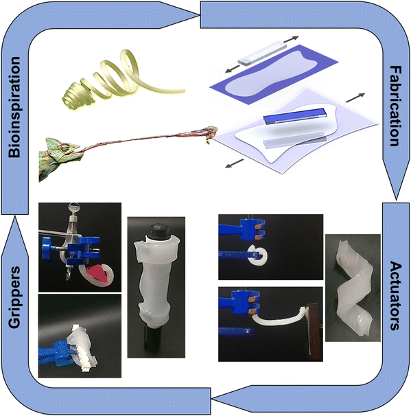
This paper presents an original approach to producing soft magnetic actuators that are inspired by nature, possess no magnetic field strength while holding objects, and offer features such as mechanical energy storage and shape recovery (see Fig. 1). To facilitate swift and adaptable actuation and recovery of soft robots, a design method has been developed that significantly enhances the elastomer's elastic strain energy. The actuator can be activated with less external energy by pre-stretching the elastomeric material, rendering it a practical solution for soft robotic applications requiring low magnetic activation. Additionally, by integrating neodymium magnets and subjecting the actuators to biaxial pre-stressing, it is possible to construct lightweight and bistable soft robotic systems that utilize the stored elastic energy as a source of power amplification to enable rapid movements.
The proposed method involves connecting a flexible elastomer to a pre-stressed elastomeric layer using a hard neodymium magnet, to create a range of pre-stressed soft magnetic actuators that utilize elastic energy storage.12,40,41 This approach is distinct from traditional magnetic grippers, which require constant external magnetic force to maintain their grip. By leveraging the elastic energy stored in the pre-stressed elastomeric layer, this design technique allows to produce soft grippers that can hold objects with zero-magnetic field strength that are heavier than their own weight, while also being able to recover their original shape. The primary advantage of this type of actuator is its ability to hold objects for an extended period of time without the need for a magnetic field, resulting in lower energy consumption within a system. Various designs have been created and evaluated to demonstrate the capabilities of this technique, which is well-suited for low-cost, simple systems that do not require continuous stimulation. The repeatability and precision of the developed actuators have been thoroughly assessed, along with their mechanical properties and potential applications.
2. Materials and methods
2.1. Design and fabrication
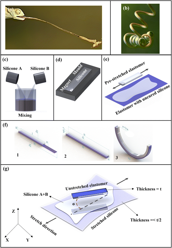
The elastic stored energy of the module is inspired by the chameleon tongue and the helical shapes are inspired by the tendrils plant as shown in Fig. 2(a) and (b).42–44 Chameleons, salamanders, and several toads shoot their sticky tongues at unaware insects up to 1.5 body lengths away, grabbing them in a 10th of a second due to the elastic energy stored in the tongues.45,46 The accelerator muscle and the laden sheath parts begin to slip across the tip of the entoglossal process, which initiates the tongue projection. The elastic energy stored in the helical fibres is made available for a simultaneous forward acceleration of the tongue pad, accelerator muscle, and retractor structures as the springs relax radially while pushing off the rounded tip of the entoglossal process.47Moreover, tendrils respond to touch and to chemical factors by curling, twining or adhering to suitable structures or hosts. Also, tendrils are touch-sensitive and prehensile. The tendril curls toward the side that is softly stroked on the tendril's bottom side after about a minute. Therefore, a soft magnetic actuator is created by attaching a flexible elastomer with a small magnet to a pre-stressed elastomeric layer, drawing inspiration from the chameleon tongue and tendrils plant.
All actuators’ moulds are created by fused deposition modelling (FDM) 3D printing technology.48 3D-printed moulds are fabricated using polylactic acid (PLA) material. All samples are designed and developed in SolidWorks© to have integrity during the process. Designs are converted into STL format and Slic3er software is used to slice the designs and generate Gcodes. Simply combining a magnet with a two-part silicone resin and moulding the resulting viscous paste yields magneto-responsive soft actuators.
Silicone elastomers (Ecoflex 00-30; Smooth-On Inc.) are mixed (see Fig. 2(c)). Then, the silicones are cured in the oven for 20 minutes at 40 °C. The cured silicone is placed into the mould and a small neodymium magnet N45SH with 10 mm diameter and 1.5 mm thickness from FIRST4MAGENTS is placed on one side of the silicone beam. The material of the magnet is NdFeB with 1700 Gauss performance, 1 kg vertical pull, 0.2 kg slide resistance, and 150 °C maximum operating temperature. The mixed silicone elastomer is cast into the mould to cover the neodymium magnet (see Fig. 2(d)). The elastomer is stretched and adhered to another elastomer without pre-stretching condition that is impregnated with silicone elastomer as shown in Fig. 2(e). The module is cured in the oven for 20 minutes at 40 °C. The module is finally trimmed from the elastomer to achieve a pre-stretched magnetic actuator. The final module is made of pure silicone without any other substances or materials. Hence, the module consists of silicone and a small permanent magnet.
2.2. Uniaxially stretched mathematical model
The potential mathematical model of our approach to the choice of self-assembly is now discussed. The mathematical model is reformulated to find out the radius of the actuators based on the previous literature.13,49 To consider massive deformations and non-zero Poisson's ratio of elastomeric materials, a continuum mechanics framework is developed. The effect of the neodymium magnet is neglected since it does not influence the energy storage of elastomers. The module is made of two varying-length elastic strips (see Fig. 2(f)). The longer strip is joined to the shorter elastomer strip at their interface after the shorter strip has been longitudinally stretched to match the length of the longer strip. The module bends to reduce its elastic energy after being released. The longer strip is under compressive stress in the final condition, whereas the shorter strip is under tensional stress.The elastic energy stored in the elastomeric layer (Ee) and the stretched elastomer layer (Es) are added together to form the actuator's overall elastic energy (Eo) to determine the actuator's curvature at equilibrium with the minimum expression of overall energy.
| Eoverall = Ee + Es | (1) |
An elastomeric layer with length l, width w, and thickness te are considered in this study. The silicone layer is stretched δ = lfinal/l. The dimensions of the elastomer become lδ, wδ−0.5, and teδ−0.5 due to the elastomer incompressibility assumption which is v equal to 0.5 and δ1δ2δ3 = 1. A second elastomer layer with an undeformed length and breadth that match the stretched elastomeric layer and a thickness of ts is then added to the stretched elastomeric layer. The radius of curvature r and length final lδfinal, both specified at the interface between the two layers, are both determined when the module is released. This causes the module to bend until it achieves an equilibrium configuration.
In bending, the module is described as Euler–Bernoulli beams which stretch ratios may be thought of as varying linearly over the thickness of the layers. The stretch along the X-axis for the elastomeric layers in the deformed coordinate system may be expressed as follows as a function of coordinate z:
| δe(z) = δfinal(1 + Γz) | (2) |
 | (3) |
 | (4) |
 | (5) |
These stretch ratios can be expressed in the undeformed coordinates of the strips (Ze for the bottom strip; Zs for the top strip; see Fig. 2(f)). Due to the incompressibility of the elastomeric layer, the stretch in the two additional orthogonal directions becomes:
| δe2 = δe3 = δ−0.5el | (6) |
Since the constant shear modulus G of the hyperelastic model can be easily understood from common material parameters, a Neo–Hookean model to determine the strain energy density of the elastomeric material is chosen. The strain energy density is assumed as:
| ee = C1(δe12 + δe22 + δe32 − 3) | (7) |
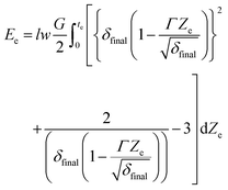 | (8) |
 | (9) |
 | (10) |
Gravity, fixed restrictions, sequential deflection, magnetic field, and other external factors all have an impact on each actuator. Therefore, the proposed theoretical model is unable to anticipate non-constant curvatures.
2.3. Spiral shape mathematical model
The procedure of the second method is like the first one. It is started by casting silicone into the mould where the small magnet is placed. Another cure elastomer-impregnated silicone sheet is stretched as shown in Fig. 2(g). The elastomer with a magnet is placed on it until the module gets cured. Finally, the module is trimmed from the excessive elastomer. Actuators are activated using a commercial neodymium magnet. The finished samples’ sizes can be based on requirements. The actuators are particularly well suited for developing actuator structures with shape recovery capabilities since pre-stretched silicone is the core.A numerical model of spiral shape is reformulated and presented based on the developed models.40,49,50 By making the angle α non-orthogonal with the direction of pre-stretch, it is possible to replicate the same anisotropy in our actuators (see Fig. 2(g)). The initial pre-stretch of the elastomeric layer, along with α, determines the helix's pitch and radius. Consider a thin silicone sheet that is elongated uni-axially and has a thickness of t/2. The elongation axis and thin direction of the stretched sheet are parallel to the x-axis and the elongation direction is supplied with a cartesian coordinate system. The results are normalized accordingly. Along the x-axis, one layer is stretched by an elongation ratio of δ. The resultant 3D reference metric of the layer is as follows when Poisson effects are ignored, and identical material characteristics are assumed for the two layers as:
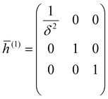 | (11) |
A cured elastomer silicone is placed on the impregnated elastomer sheet given the same coordinate system has the reference metric:
 | (12) |
Silicone is used to adhere the two stretched elastomer sheets together. The composite sheet is no longer feasible since it is impossible to have both layers at rest at the same time. The continuous metric is used to approximate the resultant discontinuous 3D metric as:
 | (13) |
The first and second reference basic forms of a thin incompatible elastic body are provided by:
ī(x,y) = ![[h with combining macron]](https://www.rsc.org/images/entities/i_char_0068_0304.gif) (x,y,0) (x,y,0) | (14) |
 | (15) |
Therefore
 | (16) |
 | (17) |
If we consider that the two layers are aligned at α
 | (18) |
 | (19) |
 | (20) |
If the actuators are narrow enough to be bending-dominated, then the relaxed helical structure's torsion is represented by τ = −M and its curvature by χ = N. We may determine that the mid-curve is a helix by substituting the values of τ and χ.
 | (21) |
 | (22) |
 | (23) |
 | (24) |
2.4. Measurement and data recording
To assess the actuator's reactions, we record and measure the actuator's behaviour in the presence of an external lateral magnetic field at various distances from the permanent magnet. When the soft composite actuators are subjected to an outside magnetic field, the experiment is run. The permanent magnet inside the actuator can control the motion. A neodymium magnet is positioned at different distances to investigate the actuator's behaviour. The magnetic field is measured using a Pasco magnetic field sensor with a probe that has a resolution of 0.01 G at a frequency of 10 Hz. The magnet's magnetic strength is recorded using PASCO Capstone. The movement of the actuator is captured by utilizing a high-speed camera, which allows for precise recording and analysis of its motion. The utilization of a high-speed camera is vital in conducting precise and accurate assessments of the actuator's functionality. In order to calculate angles, trajectory path, and deflection, PASCO software records the trajectories of the soft actuators. Moreover, a force gauge made by SAUTER with a maximum capacity of 100 N is being used to measure the tip force produced by actuator. The setup involves clamping the force gauge and the actuators from one side to ensure that the results obtained are consistent. Different pre-stretched values and magnetic field strength are recorded accordingly. Various levels of pre-stretching and magnetic field strength are documented correspondingly.2.5. Mechanical properties and cyclic behaviour
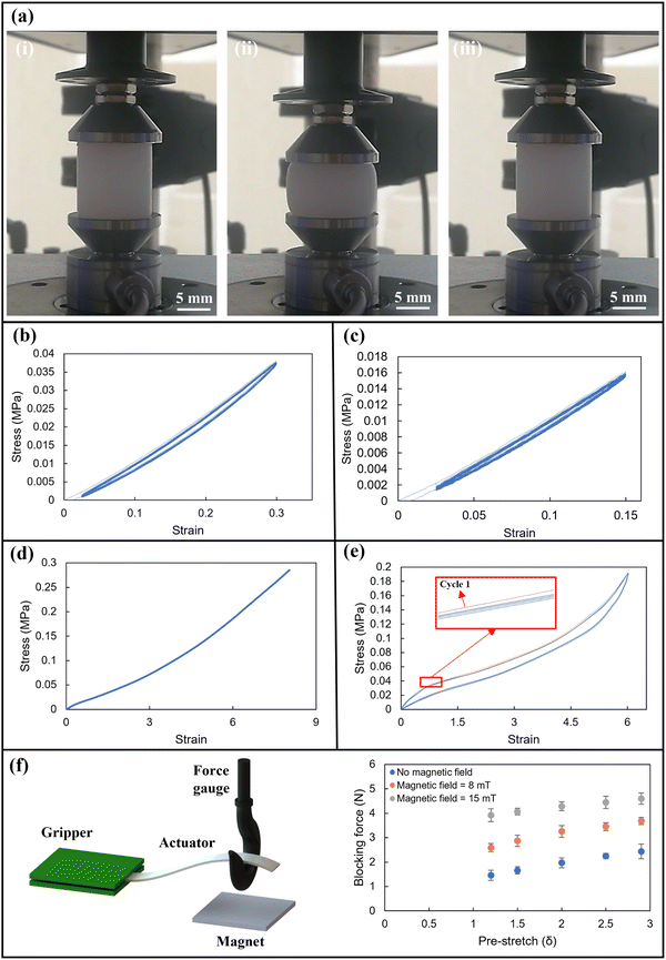
It should be highlighted that it is crucial to delay the soft actuators’ form recovery. Additionally, developing a stable soft actuator is a highly effective way to boost repeatability and precision. In order to verify the form recovery at room temperature, the cyclic load test of silicone is examined. By utilising compression tests, it is possible to measure the behaviour of silicone elastomer. The test is carried out using TA Instrument's ElectroForce® 3200. The dimensions of a cylindrical silicone are 20 mm in diameter and 20 mm in thickness. The sample is compressed using the 450 N load cell and a 0.5 Hz frequency. At room temperature, 250 cycling loads are applied for strains of 15% and 30%, respectively. The test of the silicone sample is captured on camera at high speed.The mechanical characteristics of the module (two sheet silicone adhered to each other) are evaluated using a universal mechanical testing apparatus (Shimadzu AG-X plus machine). Samples’ sizes in the form of a dog's bone are cast and tested that meets ASTM D412-C requirements. The test is carried out to compare the stresses of the samples in a cyclic load condition. The dog-bone samples are subjected to a 100 mm min−1 displacement rate while being clamped between jaws. The cyclic load is limited to 200 mm strain for 5 cycles which is greater than the expansion and shape recovery capabilities of the actuators. The cyclic load is conducted to investigate the behaviour of silicone elastomer under load. Data is gathered to see how the shape recovers on one sample after cycling loads.
3. Results and discussions
3.1. Properties of module
We investigate the mechanical behaviour of silicone elastomer using tensile and compression tests. Accordingly, the experimental stress–strain curve for cured silicone is examined. The super-elastic reaction of the silicone under the cyclic compression test is shown in Fig. 3(a). The buckling deformation results in softening–hardening section. Fig. 3(b) displays the fundamental properties of silicone elastomer, including elastic and super elastic behaviours, and softening hardening up to 15% and 30% strain. As the load is increased, the elastomer is compacted, increasing its stiffness in response.Fig. 3(b) and (c) depict the mechanical behaviour of elastomer throughout the loading–unloading cycle with 0.5 Hz speed rate for maximum stresses of 30% and 15%, respectively. Data from stress–strain experiments show that the hysteresis loop is used by elastomers to disperse and absorb energy. With the nearly constant compressive force, the structure of the elastomer exhibits a substantial distortion in the super-elastic deformation region. The elastomer is loaded to 6 mm and returns to its original shape within a few milliseconds when the structure is unloaded. It demonstrates the elastomer's capacity to absorb energy and regain its form after being unloaded at ambient temperature. The elastomer is fully recovered to its original shape in a quasi-static test condition.
The conducted results from the single and cyclic tensile tests are investigated to examine the behaviour of silicone elastomer under tensile load. Fig. 3(d) shows the behaviour of silicone in tensile tests. Engineering force–displacement data from Ecoflex 00-30's uniaxial tensile tests indicate a linear approximation of the elastic modulus for modest stresses. The cyclic tensile test is also conducted and shown in Fig. 3(e). The 5 cycles are shown to have a better understanding of elastomer behaviour. The actuator module displays elasticity and can withstand high strain rates without cracking. As the actuator expands within its length, the durability of the module is considered acceptable within this range.
The displacement reaches 200 mm for the first cycle and subsequent cycle loads. The ultimate force is almost equal for all cyclic tensile loads. The cyclic tensile loads illustrate the energy absorption and super-elastic reaction. The elastomer recovers its shape after cyclic load same as the cyclic compression test. The advantages of using pure silicone instead of paper or any other strain-limiting layer are that by increasing the load the paper is torn easily. These tests show the behaviour of elastomers under cyclic compression and tensile tests. The elastomer is capable of energy storage due to incompressibility and elastic reactions under load.
The study measured the blocking force of the actuator under different pre-stretching levels and magnetic field strengths. The experimental setup is detailed in Fig. 3(f). The results reveal a correlation between the pre-stretch values and the blocking force, with an increase in pre-stretch levels from 1.2 to 2.9 resulting in a proportional increase in blocking force from 1.3 N to 4.3 N, respectively. Moreover, it was observed that the actuator could generate force without the application of a magnetic field, owing to the presence of pre-stressed silicone. Finally, the study found that an increase in magnetic field strength from 8 mT to 15 mT is directly proportional to an increase in the blocking force of the actuators.
3.2. Model and module shapes
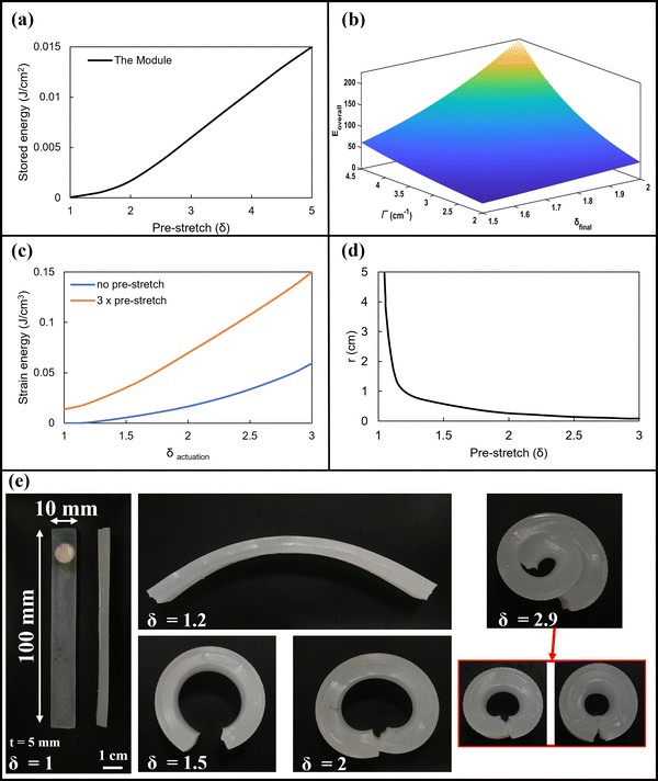
By mathematically reducing the overall energy Eoverall with δfinal and Γ, we can determine the equilibrium state of the actuator, which is in excellent accord with the experimental findings. The model's anticipated values and the values we found via our experiments accord quite well. The link between the elastic energy stored in the actuator and the pre-stretch of the elastomeric layer has also been illustrated using this mathematical model. Fig. 4(a) shows the increasing of the stored energy of the module concerning δ, highlighting the non-zero strain at the interface between the elastomeric layers.The overall energy storage in terms of δfinal and Γ is shown in Fig. 4(b). The total energy is rising by increasing the δfinal in this case up to 2. However, the total energy storage is fluctuated by changing the δfinal and Γ. Fig. 4(c) shows the strain energy over δactuation in two conditions. Even in the relaxed state, when there is no deformation from actuation, we discover that the elastic energy of the actuators is not zero since it comprises both stretching and bending energy components. Actuators are propelled up the energy landscape by this nonzero elastic energy where the energy gradient is higher. Larger pre-stretches cause strain energy to accumulate during actuation more quickly.
The relationship between pre-stretch and radius of the actuator with the same length and thickness is shown in Fig. 4(d). The values obtained from the analytical model are shown by the line. It shows by increasing the pre-stretch (δ) of the top layer (as shown in Fig. 2(f)), the radius of the final module is decreased which is in an agreement with Fig. 4(e). By increasing the thickness of the module, the same results are conducted accordingly. The actuator strips with an overall thickness of 5 mm are stretched in different ways as shown in Fig. 4(e). Images are taken from samples showing curved actuators create by making pre-stretch at five distinct δ values. The modules have values for te and ts of 3 and 2 mm, respectively. The results in Fig. 4(e) show they are in agreement with the analytical model. For clarity, the modules with δ values from 1 to 2.9 are sliced to reveal the curve of the beam.
The module with the 2.9 δ value is cut in half and the beam is bent with high radius curvature in relax stage. Greater curvature is correlated with larger values of δ. No buckling which negatively affects the actuator's ability to respond and recover occurs due to the excessive pre-stretch of the elastomer. The module does not curl when δ = 1. The radius of curvature of the final structures reduced as the pre-stretch increased. The degree of the resultant curvature may also be managed by varying the thickness of the elastomer. Greater values of radius at the same stretch can be obtained with thinner elastomer layers because the initial strip's deformation is less constrained.12,13
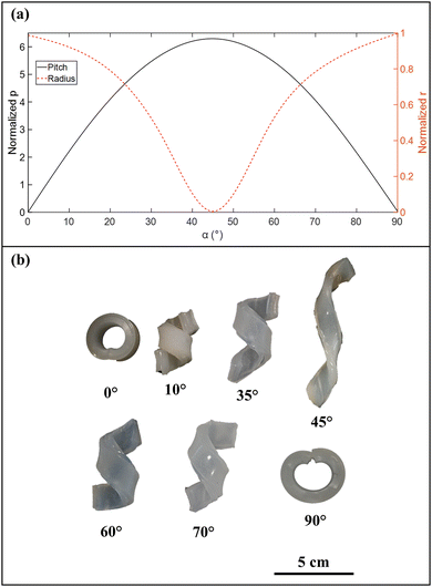
We created coiling modules by stretching a silicone-impregnated elastomeric layer longitudinally and then attaching a non-stretched elastomer with a larger thickness to it. The module can create a continuous helix by twisting one of its ends after it separates from the support.13,40 By adjusting parameters such as radius and pitch developed in the mathematical model, spiral actuators are created. Following the actuator's assembly, the elastomer is pre-stressed and given a stretch that causes it to curl evenly with a radius of curvature. The radius and pitch rely on the angle of attachment and the results of the analytical model are shown in Fig. 5(a). Also, Fig. 5(b) illustrates the modules that are developed experimentally. The pitch of the samples decreases by increasing the angle. The size of the modules is equal to 100 mm in length, 10 mm in width and 5 mm in thickness.
It illustrates how these actuators’ radius of curvature decreases as the pre-stretch rises. The modules can withstand significant deformations without suffering harm since they are composed of elastomeric materials, which allows the springs to return to their original shape even after being stretched to their maximum length in a linear geometry. The variables fit under the “narrow” regime. The longitudinal axis of the strips is parallel to the major axis of curvature for α = 0° and α = 90°. The generated forms are round and have a curvature that is about equivalent to the corresponding primary curvature. The pitch rises and the radius falls as α grows from 0° to 45°, reaching a pure twist at 45°. After 45°, the radius of the module increases while the pitch decreases.
3.3. Actuator's performance
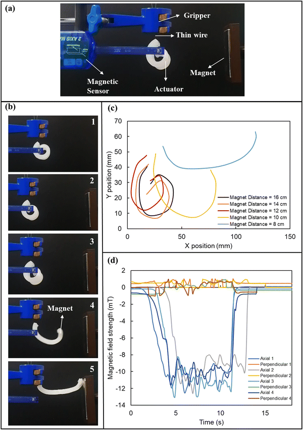
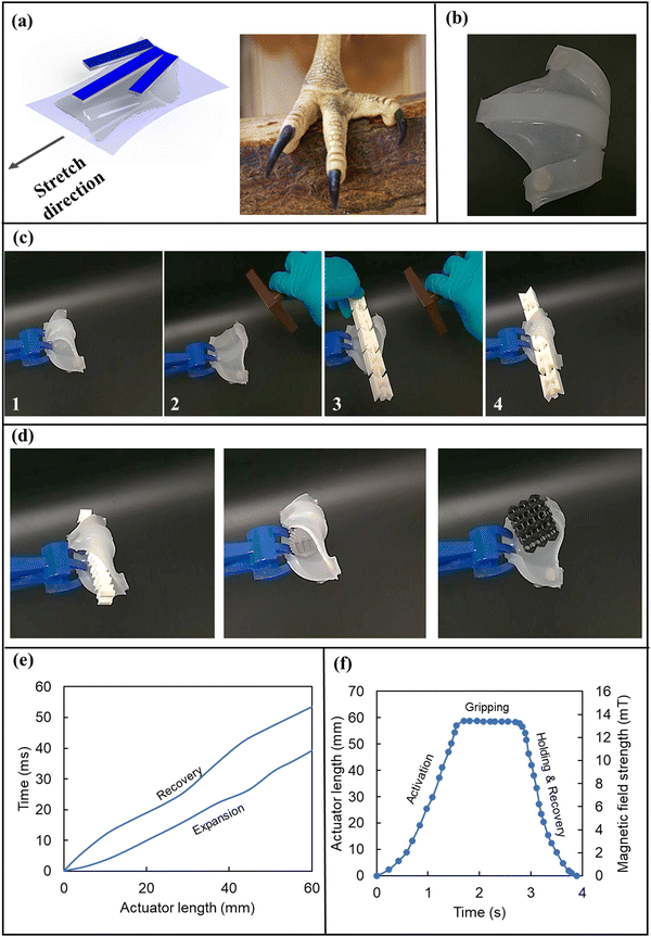
The location of the unstretched elastomer layer and the careful pre-stretching of the elastomeric layer allow the encoding of actuation sequences in actuators with a single small magnet. When the actuator is not stimulated by the magnetic field, the pre-stressed elastomer's elastic energy causes the actuator to curl (relaxed state). When it is activated, the pre-stressed elastomer expands. Any additional strain imposed by actuation causes a rapid build-up of elastic energy, which causes strong restoring forces and a swift return of the actuator to its relaxed condition.The strain energy stored in the actuators allows for their quick recovery after actuation. We use the actuator with a length of 75 mm and a thickness of 5 mm. The actuator's weight is 5 ± 0.2 grams. Fig. 6(a) illustrates the equipment and procedure employed during the experiment. In order to track the movement of the actuator while it is not fully clamped, it is held by a thin wire. The aim is to investigate the behaviour of actuators when it is not restricted. Therefore, the actuator detaches a little bit. During the experiment, the distance between the magnet and the actuator is reduced while the sensor measures the magnetic field. Additionally, the high-speed camera continuously records the procedure. The captured video is then uploaded into PASCO Capstone, and software is used to extract the trajectory of the actuator's movement accurately. The magnet attracts the actuator when the distance between the actuator and the permanent magnet becomes 8 cm. Reducing the distance from 16 cm to 8 cm results in attracting the actuator in 35 ms. The attraction expands the actuator's length 3 times larger than the relaxed form (see Fig. 6(b)). The actuator can regain its original form within 43 ms when the magnetic field is removed. This happens because the strain energy that has accumulated in the elastomer produces a strong restoring force. The actuator mimics the salamander tongue.
Fig. 6(c) depicts the path taken by the actuator during its extension by PASCO Capstone software. The extension of the actuator is recorded in presence of a magnet at different distances. Changes in the shape of the actuator are tangible as the magnet is getting closer. The magnetic field changes are recorded during the activation of the module. Fig. 6(d) illustrates the axial and perpendicular field strength changes due to the existence of 2 magnets. We run 4 times to investigate the differences accordingly. The magnetic field is in the opposite direction and the values of magnetic field strength are negative. The axial field strength is started from 0 and by decreasing the distance, the maximum value of −13 mT is achieved. The magnet is held for 7 s to evaluate the field changes. The field strength fluctuates between −13 mT and −9 mT. The perpendicular field strength fluctuates between −1 mT to 1 mT in all runs. The attraction of the actuator can be performed from a long distance as well. The actuator can be activated remotely if a stronger magnet is used accordingly. Also, electromagnetic magnets or coils can eliminate the use of a permanent magnet for actuator activation.
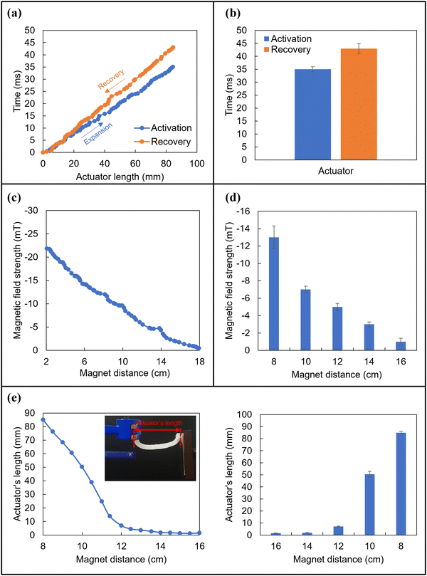
The deformation of the actuator versus recovery time experiment is also conducted accordingly. The experiment is done by the length of the stimulated actuator over time step by step. The end of the actuator where the permanent magnet is placed is trajected using a high-speed camera. The actuator is fully expanded in 35 ms when the permanent magnet is positioned at 8 cm as shown in Fig. 7(a). Meanwhile, after removing the permanent magnet the actuator goes back to its initial shape. The time that the actuator recovers its shape is 43 ms. The procedures for both activation and shape recovery are repeated five times and the results are shown in Fig. 7(b). Meanwhile, the changes in the magnetic field strength by changing the distance of the magnet are recorded accordingly.
Fig. 7(c) illustrates by increasing the distance of the magnet from 2 cm to 18 cm, the strength of the magnetic field is decreased from −22 mT to almost −0.5 mT. The procedure is repeated 50 times and the magnetic field is measured at different specific distances. Fig. 7(d) shows the changes in field strength at different distances of the magnet from the actuator. The repeatability and precision of the actuator are measured as well. Fig. 7(e) shows by increasing the magnet's distance, the actuator's length is decreased as well. The actuator's length from the start of the module to the end of it is shown in Fig. 7(e). The procedure is repeated 5 times and the actuator's length is measured using Capstone software (see Fig. 7(e)).
3.4. Gripper
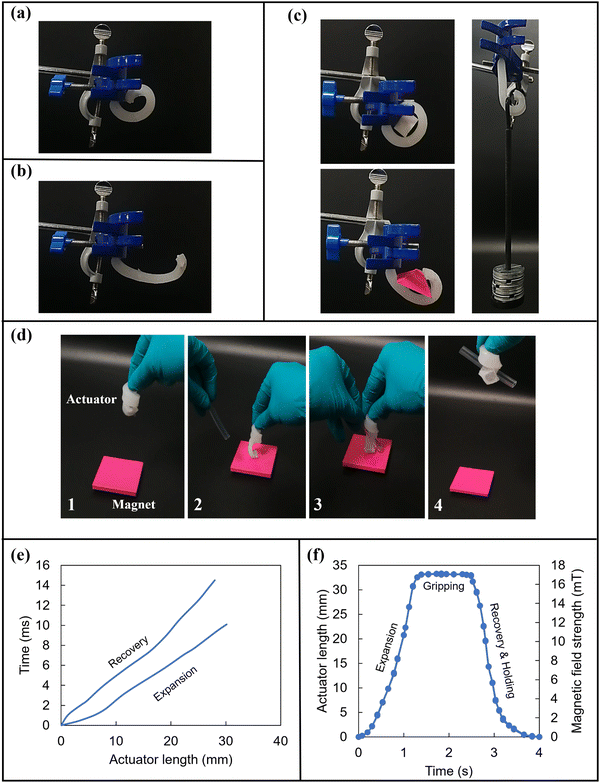
We perform a lifting and holding operation using both simple and helical actuators and a permanent magnet. The actuator in relaxed form can hold and lift various objects with different shapes and weights. The actuator is clamped from one side to perform the task as shown in Fig. 8(a). The permanent magnet is held at a distance of 10 cm from the actuator to activate it (see Fig. 8(b)). The actuator is activated by the magnet and objects are held in a stable condition accordingly as shown in Fig. 8(c). It can hold weights up to 100 grams which is 20 times heavier than the actuator's weight in relaxed form without an external magnetic field. The ability to hold objects in a horizontal direction is also shown in Fig. 8(c). The actuator is activated and expanded completely in 30 ms and it can hold the objects without the presence of the magnetic field. The holding time can be continued until the actuator is activated again since the shape is locked in the holding position. The implementation of real-time controllability of the gripping force and magnetic intensity can be easily done in a system using electromagnets.Meanwhile, the helical actuator uncoils upon magnetic activation and recoil when the magnet is removed. The actuator may conformally helical wrap around long, narrow objects thanks to this elastic recovery, which also retains its zero-magnetic field hold. The actuator with an angle of 15° is used to perform this task. The helical actuator is activated while under magnetic field strength and re-coil when the magnetic field is released. This elastic recovery makes it possible for the actuator to conformally helical wrap around long, narrow objects while still maintaining their zero-magnetic field hold. The helical actuator is activated and grasps the plastic tube as shown in Fig. 8(d). To maintain the gripper wrapped around the object throughout pick-up, translation, and repositioning, no additional power source is needed. The limitations such as grasping and releasing tasks for different objects can be easily performed by electromagnet instead of permanent magnet. In the first step of this process, the initial actuator is brought in proximity to the magnet. Once in range, the actuator is triggered and opens the last pitch, creating a gap for the sample to be placed upon. The sample is carefully positioned on the last pitch and once it is in place, the last pitch is closed. The actuator is then able to hold the object firmly in place without the need for any external magnetic field strength. This method allows for a secure and stable grip on the object being held, even in situations where there is a lack of a strong magnetic field.
The behaviour of these actuators is basically the opposite of that of typical soft magnetic grippers which need a continuous magnetic field to hold the object. The second part of the helical expansion and shape recovery is recorded as shown in Fig. 8(e). The end of the actuator expands and recovers its shape in almost 21 ms. Fig. 8(f) shows the time from activation to holding with zero-magnetic field strength. The results show the helical actuator expands and recovers its shape by gripping the object. Fig. 8(f) illustrates that the actuator's length can increase up to 34 mm as the distance between the magnet and the actuator is reduced over time. When the distance between the magnet and the actuator is increased, the actuator returns to its initial relaxed stage. Additionally, a magnetic sensor is employed to measure the magnetic field, which is found to increase up to 17 mT when the distance between the magnet and the actuator is decreased. Conversely, when the distance is increased, the field strength is diminished. It should be noted the speed of performing a task can be increased in a more advanced system.
Developing multiple designs and shapes is the advantage of this method. With the help of the elastic energy stored in their tendons and bones, the anatomy of many birds allows them to perch without employing any field strength. A bioinspired design gripper is developed based on bird's feet. The strategy is a combination of previous fabrication methods. The schematic of the design is shown in Fig. 9(a). A long and two short modules with 3 mm thickness are attached to the pre-stretched sheet with 2 mm thickness. The angle of short modules is equal and around 30°. The length of modules can be varied based on requirements. The design is trimmed from the elastomer sheet as shown in Fig. 9(b). Permanent magnets are used in short modules to distribute the weight and make the actuator more stable. The procedure for gripping the object is shown in Fig. 9(c). The actuator is stimulated and expanded in presence of a magnetic field and grasps the object. By removing the magnetic field, the actuator goes back to its initial form due to the stored energy. The shape recovery of the actuator is within 42 ms. The bioinspired gripper can hold objects with different shapes and designs as shown in Fig. 9(d). The shape expansion, recovery, gripping, and holding object of the actuator are shown in Fig. 9(e) and (f). The actuator performs the complete task in 4 seconds in this condition with 14 mT magnetic field strength. Similar to Fig. 8(f), the process depicted in Fig. 9(f) involves the actuator's length increasing as the distance between the magnet and the actuator is reduced. However, in this case, the actuator is longer and the magnetic field reaches a value of 14 mT.
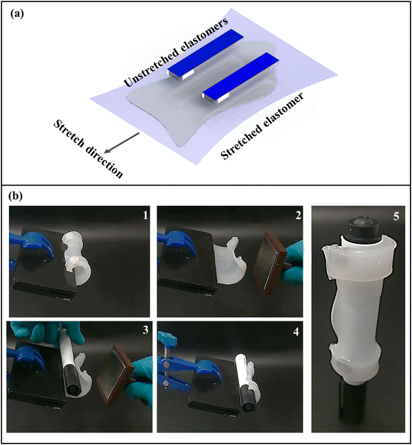
To make the actuator simple and increase the contact area, a sheet shape actuator is designed and developed as shown in Fig. 10(a). The elastomer with a thickness of 2 mm is stretched and two modules with a 3 mm thickness and permanent magnets are placed on the elastomer. The elastomer is stretched out to a maximum of δ = 2 and the two modules prevent wrinkles of the whole actuator. A flat sheet shape actuator is developed using this technique. The distance between each actuator can be varied based on the requirements. The benefit of this type of actuator is a larger contact area to grasp and hold a variety of shapes. An example of holding and grasping using this actuator is shown in Fig. 10(b). The procedure is starting with actuating the clamped module with a permanent magnet with a field strength of 13 mT. The object with a diameter of 17 mm is grasped and held with zero field strength. This actuator's soft arms can adapt to the object being held, maximising the area of contact, and enabling catching and zero-field strength holding. The ultimate gripping force is dependent on the elastic energy stored in the actuator, although the gripping force delivered by the actuator may be modified if the magnetic field is activated during grasping. The advantage of a bird-foot gripper over a flat-sheet one of the same size is the bird-foot one can grasp and hold cubic shape objects like meta-structures that the flat-sheet one cannot perform the task as shown in Fig. 9(d). However, if the size of the flat-sheet actuator becomes bigger, it can hold and grasp objects like samples in Fig. 9(d).
In the field of magnetic actuators, there is always a continuous effort to develop more efficient and effective devices. To assess the performance of a newly developed magnetic actuator, a comparison was conducted between it and its predecessors. The findings of the comparison are presented in Table 1. According to the results, the newly developed magnetic actuator outperforms its predecessors in two significant ways. Firstly, it has a shorter response time, which means that it can activate more quickly in response to external stimuli. This can be a critical factor in certain applications, such as robotics, where speed and precision are essential. Secondly, the new actuator requires less magnetic field strength to be activated. This means that it can be used in environments where magnetic fields are weaker, making it a more versatile and adaptable device. Furthermore, the newly developed magnetic actuator has an additional advantage over previous versions when it comes to long-term holding tasks. Unlike its predecessors, it does not require magnetic field strength to maintain its hold over extended periods. This can be especially beneficial in applications where power consumption is a critical factor or in situations where a constant magnetic field cannot be maintained.
| Work | Actuation | Activation field strength (mT) | Long-time holding | Responsive time |
|---|---|---|---|---|
| Lalegani Dezaki et al.34 | Magnetic | 15–35 | Magnetic field required | Not available |
| Zhang et al.51 | Magnetic | Not available | Not available | 1.32 s |
| Zhang et al.37 | Magnetic | Not avaialable | No magnetic field required | 112 ms |
| Qi et al.38 | Magnetic | 50–200 | Magnetic field required | 120 ms |
| Tang et al.52 | Magnetic | 5–100 | Magnetic field required | 0.4–0.5 s |
| Carpenter et al.53 | Magnetic | 10–70 | Magnetic field required | 160–400 ms |
| This work | Magnetic | 5–20 | No magnetic field required | 35–40 ms |
Straightforward production, easy to use, and zero field strength holding are the advantages of these actuators instead of previous magnetic actuators. The ability to regulate the size and direction of the pre-stretch in actuators allows us to customise the elastic modules and programme the resulting motion of the soft actuator with a single material, even though choosing a stiffer material would also serve to increase the restoring forces. Also, it is possible to use a customised small electromagnet to control, attract, and release the actuator with high accuracy. The actuator's size and design can be modified based on the requirement. The assembly elastomeric module allows for the programming of alternative actuation sequences in soft actuators. Without pre-stretching, combining silicones with the same properties would only provide access to discrete stiffness values based on the bulk characteristics of those silicones. Also, choosing a stronger magnet leads to faster actuation. However, the design should accommodate the magnet properly.
4. Conclusion
This paper presents a novel type of soft magnetic actuator inspired by biological systems that use elastic energy stored in an elastomeric layer to produce a variety of mechanical properties and reactions. The actuators can be easily created from stretched planar elastomeric strips or sheets using a simple and affordable manufacturing process that involves permanent magnets and silicone elastomer. A numerical model was developed to investigate the energy storage of pre-stretched elastomers, the radius of the actuator in its relaxed form, and the pitch and radius of helical-shaped modules. The behaviour of the silicone elastomer module was examined under cyclic compression and tension tests. The analytical model showed that increasing the pre-stretch resulted in increased stored and strain energy, while decreasing the radius of the actuator in its relaxed stage. The numerical model demonstrated that the pitch and radius of helical-shaped actuators followed a predictable pattern. The silicone elastomer regained its original shape quickly when subjected to cycling stresses at room temperature. The simple beam shape actuator was able to hold a weight 20 times heavier than its own weight with zero magnetic field strength, and the actuator could be regulated using a weaker magnetic field. The actuator could be triggered with a magnetic field strength of less than 25 mT. This technique can be used to develop different shapes and designs of soft actuators with high contact areas and stability, such as soft grippers that can be used in robotic grippers and other technical domains. The combination of an energy storage structure and magnetic actuation can provide quick and extensive deformation without the need for complicated structures.Data availability
The data that support the findings of this study are available from the corresponding author upon reasonable request.Conflicts of interest
The authors declare no conflict of interest.Acknowledgements
The authors gratefully acknowledge use of the services and facilities at Nottingham Trent University.References
- S. Coyle, C. Majidi, P. LeDuc and K. J. Hsia, Bio-inspired soft robotics: Material selection, actuation, and design, Extreme Mech. Lett., 2018, 22, 51–59, DOI:10.1016/j.eml.2018.05.003.
- S. Kim, C. Laschi and B. Trimmer, Soft robotics: A bioinspired evolution in robotics, Trends Biotechnol., 2013, 31(5), 287–294, DOI:10.1016/j.tibtech.2013.03.002.
- J. M. Wilson and E. P. Flanagan, The role of elastic energy in activities with high force and power requirements: A brief review, J. Strength Cond. Res., 2008, 22(5), 1705–1715, DOI:10.1519/JSC.0b013e31817ae4a7.
- T. I. Zack, T. Claverie and S. N. Patek, Elastic energy storage in the mantis shrimp's fast predatory strike, J. Exp. Biol., 2009, 212(24), 4002–4009, DOI:10.1242/jeb.034801.
- T. H. Quinn and J. J. Baumel, The digital tendon locking mechanism of the avian foot (aves), Zoomorphology, 1990, 109(5), 281–293, DOI:10.1007/BF00312195.
- A. G. Volkov, V. A. Murphy, J. I. Clemmons, M. J. Curley and V. S. Markin, Energetics and forces of the dionaea muscipula trap closing, J. Plant Physiol., 2012, 169(1), 55–64, DOI:10.1016/j.jplph.2011.08.003.
- J. Yu, S. Chary, S. Das, J. Tamelier, N. S. Pesika and K. L. Turner, et al., Gecko-inspired dry adhesive for robotic applications, Adv. Funct. Mater., 2011, 21(16), 3010–3018, DOI:10.1002/adfm.201100493.
- S. Wei and T. K. Ghosh, Bioinspired structures for soft actuators, Adv. Mater. Technol., 2022, 7(10), 2101521, DOI:10.1002/admt.202101521.
- C. P. McGowan, J. Skinner and A. A. Biewener, Hind limb scaling of kangaroos and wallabies (superfamily macropodoidea): Implications for hopping performance, safety factor and elastic savings, J. Anat., 2008, 212(2), 153–163, DOI:10.1111/j.1469-7580.2007.00841.x.
- M. B. Bennett and G. C. Taylor, Scaling of elastic strain energy in kangaroos and the benefits of being big, Nature, 1995, 378(6552), 56–59, DOI:10.1038/378056a0.
- X. Huang, K. Kumar, M. K. Jawed, A. Mohammadi Nasab, Z. Ye and W. Shan, et al., Highly dynamic shape memory alloy actuator for fast moving soft robots, Adv. Mater. Technol., 2019, 4(4), 1800540, DOI:10.1002/admt.201800540.
- B. J. Cafferty, V. E. Campbell, P. Rothemund, D. J. Preston, A. Ainla and N. Fulleringer, et al., Fabricating 3D structures by combining 2D printing and relaxation of strain, Adv. Mater. Technol., 2019, 4(1), 1800299, DOI:10.1002/admt.201800299.
- A. Pal, D. Goswami and R. V. Martinez, Elastic energy storage enables rapid and programmable actuation in soft machines, Adv. Funct. Mater., 2020, 30(1), 1906603, DOI:10.1002/adfm.201906603.
- C. Majidi, Soft-matter engineering for soft robotics, Adv. Mater. Technol., 2019, 4(2), 1800477, DOI:10.1002/admt.201800477.
- A. Zolfagharian, S. Gharaie, A. Z. Kouzani, M. Lakhi, S. Ranjbar and M. Lalegani Dezaki, et al., Silicon-based soft parallel robots 4D printing and multiphysics analysis, Smart Mater. Struct., 2022, 31(11), 115030, DOI:10.1088/1361-665X/ac976c.
- X. P. Hao, C. W. Zhang, W. Hong, M. Meng, L. X. Hou and M. Du, et al., Engineering viscoelastic mismatch for temporal morphing of tough supramolecular hydrogels, Mater. Horiz., 2023, 10(2), 432–442, 10.1039/D2MH01339H.
- J. Rossiter, Soft robotics: The route to true robotic organisms, Artif. Life Robot., 2021, 26(3), 269–274, DOI:10.1007/s10015-021-00688-w.
- M. Lalegani Dezaki and M. Bodaghi, Shape memory meta-laminar jamming actuators fabricated by 4D printing, Soft Matter, 2023, 19(12), 2186–2203, 10.1039/D3SM00106G.
- Y. Cao and J. Dong, Programmable soft electrothermal actuators based on free-form printing of the embedded heater, Soft Matter, 2021, 17(9), 2577–2586, 10.1039/D0SM02062A.
- W. Dou, G. Zhong, J. Cao, Z. Shi, B. Peng and L. Jiang, Soft robotic manipulators: Designs, actuation, stiffness tuning, and sensing, Adv. Mater. Technol., 2021, 6(9), 2100018, DOI:10.1002/admt.202100018.
- L. Marechal, P. Balland, L. Lindenroth, F. Petrou, C. Kontovounisios and F. Bello, Toward a common framework and database of materials for soft robotics, Soft Robot., 2021, 8(3), 284–297, DOI:10.1089/soro.2019.0115.
- Y. Tang, M. Li, T. Wang, X. Dong, W. Hu and M. Sitti, Wireless miniature magnetic phase-change soft actuators, Adv. Mater., 2022, 34(40), 2204185, DOI:10.1002/adma.202204185.
- N. Bira, P. Dhagat and J. R. Davidson, A review of magnetic elastomers and their role in soft robotics, Front. Robot. AI, 2020, 7, 588391, DOI:10.3389/frobt.2020.588391.
- X. Dong, X. Luo, H. Zhao, C. Qiao, J. Li and J. Yi, et al., Recent advances in biomimetic soft robotics: Fabrication approaches, driven strategies and applications, Soft Matter, 2022, 18(40), 7699–7734, 10.1039/D2SM01067D.
- N. Deng, J. Li, H. Lyu, R. Huang, H. Liu and C. Guo, Degradable silk-based soft actuators with magnetic responsiveness, J. Mater. Chem. B, 2022, 10(37), 7650–7660, 10.1039/D2TB01328B.
- X. Zhao, S. Liu, G. A. Parada and Y. Kim, Ferromagnetic soft continuum robots, Sci. Robot., 2019, 4(33), eaax7329, DOI:10.1126/scirobotics.aax7329.
- G. Dong, Q. He and S. Cai, Magnetic vitrimer-based soft robotics, Soft Matter, 2022, 18(39), 7604–7611, 10.1039/D2SM00893A.
- Y. Qi, C. Zhou, Y. Qiu, X. Cao, W. Niu and S. Wu, et al., Biomimetic janus photonic soft actuator with structural color self-reporting, Mater. Horiz., 2022, 9(4), 1243–1252, 10.1039/D1MH01693H.
- Y. Chi, Y. Li, Y. Zhao, Y. Hong, Y. Tang and J. Yin, Bistable and multistable actuators for soft robots: Structures, materials, and functionalities, Adv. Mater., 2022, 34(19), 2110384, DOI:10.1002/adma.202110384.
- H. Tao, D. Yue and C. Li, A fast self-healing magnetic nanocomposite for magnetic actuators, Macromol. Mater. Eng., 2022, 307(2), 2100649, DOI:10.1002/mame.202100649.
- X. Hu, Z. Ge, X. Wang, N. Jiao, S. Tung and L. Liu, Multifunctional thermo-magnetically actuated hybrid soft millirobot based on 4D printing, Composites, Part B, 2022, 228, 109451, DOI:10.1016/j.compositesb.2021.109451.
- A. de Oliveira Barros, M. N. Hasan Kashem, D. Luna, W. J. Geerts, W. Li and J. Yang, Magnetic properties of PDMS embedded with strontium ferrite particles cured under different magnetic field configurations, AIP Adv., 2022, 12(3), 035121, DOI:10.1063/9.0000338.
- L. Shi and S. Guo, Development and evaluation of a venus flytrap-inspired microrobot, Microsyst. Technol., 2016, 22(8), 1949–1958, DOI:10.1007/s00542-015-2484-9.
- M. Lalegani Dezaki and M. Bodaghi, Soft magneto-responsive shape memory foam composite actuators, Macromol. Mater. Eng., 2022, 307(11), 2200490, DOI:10.1002/mame.202200490.
- Z. Wang, Y. Wu, D. Wu, D. Sun and L. Lin, Soft magnetic composites for highly deformable actuators by four-dimensional electrohydrodynamic printing, Composites, Part B, 2022, 231, 109596, DOI:10.1016/j.compositesb.2021.109596.
- K. T. Nguyen, H. Lee, J. Kim, E. Choi, J. Park and C. Kim, A composite electro-permanent magnetic actuator for microrobot manipulation, Int. J. Mech. Sci., 2022, 229, 107516, DOI:10.1016/j.ijmecsci.2022.107516.
- Z. Zhang, X. Li, X. Yu, H. Chai, Y. Li and H. Wu, et al., Magnetic actuation bionic robotic gripper with bistable morphing structure, Compos. Struct., 2019, 229, 111422, DOI:10.1016/j.compstruct.2019.111422.
- S. Qi, H. Guo, J. Fu, Y. Xie, M. Zhu and M. Yu, 3D printed shape-programmable magneto-active soft matter for biomimetic applications, Compos. Sci. Technol., 2020, 188, 107973, DOI:10.1016/j.compscitech.2019.107973.
- M. Lalegani Dezaki and M. Bodaghi, Magnetorheological elastomer-based 4D printed electroactive composite actuators, Sens. Actuators, A, 2023, 349, 114063, DOI:10.1016/j.sna.2022.114063.
- E. Sharon, R. Kupferman, E. Efrati and S. Armon, Geometry and mechanics in the opening of chiral seed pods, Science, 2011, 333(6050), 1726–1730, DOI:10.1126/science.1203874.
- H. C. Koch, D. Schmelzeisen and T. Gries, 4D textiles made by additive manufacturing on pre-stressed Textiles—An overview, Actuators, 2021, 10(2), 31, DOI:10.3390/act10020031.
- K. Müller U.e and S. Kranenbarg, Power at the tip of the tongue, Science, 2004, 304(5668), 217–219, DOI:10.1126/science.1097894.
- S. M. Deban, J. C. O’Reilly, U. Dicke and J. L. van Leeuwen, Extremely high-power tongue projection in plethodontid salamanders, J. Exp. Biol., 2007, 210(4), 655–667, DOI:10.1242/jeb.02664.
- S. J. Gerbode, J. R. Puzey, A. G. McCormick and L. Mahadevan, How the cucumber tendril coils and overwinds, Science, 2012, 337(6098), 1087–1091, DOI:10.1126/science.1223304.
- A. Herrel, C. L. Redding, J. J. Meyers and K. C. Nishikawa, The scaling of tongue projection in the veiled chameleon, chamaeleo calyptratus, Zoology, 2014, 117(4), 227–236, DOI:10.1016/j.zool.2014.01.001.
- R. E. Lombard and D. B. Wake, Tongue evolution in the lungless salamanders, family plethodontidae I. introduction, theory and a general model of dynamics, J. Morphol., 1976, 148(3), 265–286, DOI:10.1002/jmor.1051480302.
- J. H. de Groot and J. L. van Leeuwen, Evidence for an elastic projection mechanism in the chameleon tongue, Proc. R. Soc. London, Ser. B, 2004, 271(1540), 761–770, DOI:10.1098/rspb.2003.2637.
- M. Lalegani Dezaki, M. K. A. Mohd Ariffin and S. Hatami, An overview of fused deposition modelling (FDM): Research, development and process optimisation, Rapid Prototyp. J., 2021, 27(3), 562–582, DOI:10.1108/RPJ-08-2019-0230.
- R. M. Erb, J. S. Sander, R. Grisch and A. R. Studart, Self-shaping composites with programmable bioinspired microstructures, Nat. Commun., 2013, 4(1), 1712, DOI:10.1038/ncomms2666.
- J. Liu, J. Huang, T. Su, K. Bertoldi and D. R. Clarke, Structural transition from helices to hemihelices, PLoS One, 2014, 9(4), e93183, DOI:10.1371/journal.pone.0093183.
- Z. Zhang, D. Chen, H. Wu, Y. Bao and G. Chai, Non-contact magnetic driving bioinspired venus flytrap robot based on bistable anti-symmetric CFRP structure, Compos. Struct., 2016, 135, 17–22, DOI:10.1016/j.compstruct.2015.09.015.
- D. Tang, C. Zhang, H. Sun, H. Dai, J. Xie and J. Fu, et al., Origami-inspired magnetic-driven soft actuators with programmable designs and multiple applications, Nano Energy, 2021, 89, 106424, DOI:10.1016/j.nanoen.2021.106424.
- J. A. Carpenter, T. B. Eberle, S. Schuerle, A. Rafsanjani and A. R. Studart, Facile manufacturing route for magneto-responsive soft actuators, Adv. Intell. Syst., 2021, 3(8), 2000283, DOI:10.1002/aisy.202000283.
| This journal is © The Royal Society of Chemistry 2023 |

