
 Open Access Article
 This Open Access Article is licensed under a
 Creative Commons Attribution 3.0 Unported Licence
Robust fabrication of ultra-soft tunable PDMS microcapsules as a biomimetic model for red blood cells†
Qi
Chen
 ab,
Naval
Singh
ab,
Kerstin
Schirrmann
ab,
Qi
Zhou
c,
Igor L.
Chernyavsky
de and
Anne
Juel
*ab
ab,
Naval
Singh
ab,
Kerstin
Schirrmann
ab,
Qi
Zhou
c,
Igor L.
Chernyavsky
de and
Anne
Juel
*ab
aManchester Centre for Nonlinear Dynamics, The University of Manchester, Manchester, M13 9PL, UK. E-mail: anne.juel@manchester.ac.uk
bDepartment of Physics and Astronomy, The University of Manchester, Manchester, M13 9PL, UK
cSchool of Engineering, Institute for Multiscale Thermofluids, The University of Edinburgh, Edinburgh, EH9 3FB, UK
dDepartment of Mathematics, The University of Manchester, Manchester, M13 9PL, UK
eMaternal and Fetal Health Research Centre, School of Medical Sciences, The University of Manchester, Manchester, M13 9WL, UK
First published on 10th May 2023
Abstract
Microcapsules with liquid cores encapsulated by thin membranes have many applications in science, medicine and industry. In this paper, we design a suspension of microcapsules which can flow and deform like red blood cells (RBCs), as a valuable tool to investigate microhaemodynamics. A reconfigurable and easy-to-assemble 3D nested glass capillary device is used to robustly fabricate water-oil-water double emulsions which are then converted into spherical microcapsules with hyperelastic membranes by cross-linking the polydimethylsiloxane (PDMS) layer coating the droplets. The resulting capsules are monodisperse to within 1% and can be made in a wide range of size and membrane thickness. We use osmosis to deflate by 36% initially spherical capsules of diameter 350 μm and a membrane thickness of 4% of their radius. Hence, we can match the reduced volume of RBCs but not their biconcave shape, since our capsules adopt a buckled shape. We compare the propagation of initially spherical and deflated capsules under constant volumetric flow in cylindrical capillaries of different confinements. We find that only deflated capsules deform broadly like RBCs over a similar range of capillary numbers Ca – the ratio of viscous to elastic forces. Similarly to the RBCs, the microcapsules transition from a symmetric ‘parachute’ to an asymmetric ‘slipper’-like shape as Ca increases within the physiological range, demonstrating intriguing confinement-dependent dynamics. In addition to biomimetic RBC properties, high-throughput fabrication of tunable ultra-soft microcapsules could be further functionalized and find applications in other areas of science and engineering.
1 Introduction
Microcapsules with core–shell structures are widely used in industrial and biomedical domains, such as thermal energy storage,1 enhanced oil recovery,2 targeted drug delivery and controlled release,3,4 and cell encapsulation and culture.5 They also occur naturally in the form of, e.g., red blood cells (RBCs), bacteria and egg cells. Capsules that are used as carriers in confined media of complex geometry, e.g., enhanced oil recovery and biological delivery systems, have to be highly deformable and sufficiently robust to propagate efficiently and reach their targets. For example, the high deformability of RBCs enables them to flow through narrow pores and vessels of comparable size to deliver oxygen from the lungs to the rest of the body and carry carbon dioxide back to the lungs to be exhaled. Due to their high deformability, RBCs can adopt a variety of shapes in confined flow, including symmetrical parachute and symmetry-broken slipper-like shapes6,7 (see Fig. 1) for sufficiently large capillary numbers Ca – a measure of the ratio of viscous to elastic forces acting on the capsule. Although the flow of isolated capsules (or RBCs) in confined vessels has been extensively studied,8 the fluid dynamics of capsule suspensions is yet to be fully addressed, including their propagation in complex media9 and rheological properties.10 | ||
| Fig. 1 Steadily propagating RBCs in a cylindrical glass capillary tube.6 The parachute-like shape on the left is approximately axisymmetric, in contrast with the slipper-like shape on the right. | ||
Recently, numerical simulations have been applied to investigate the dynamics of RBC suspensions in some complex geometries. However, they are usually limited to low haematocrit (or RBC volume fraction) or small flow domains because of their computational expense.9 The use of real RBCs in controlled experiments is also challenging because of their small size (typically less than 10 μm), fragility, biological variability, rapid ageing and limited availability.11,12 Thus, various analogue models including capsules, elastic beads, vesicles and droplets have been developed to mimic flow behaviours of RBCs.13–15 Capsules have a core-membrane structure similar to RBCs and they typically exhibit larger deformations under flow than solid elastic beads.8,16 Lee and Fung17 and Seshadri et al.18 proposed early prototypes of capsule models based on latex balloons. Although vesicles19 and droplets20 can also deform considerably, they do not exhibit the shear elasticity of real RBCs.21 Undesired coalescence of droplets further limits their use to dilute suspensions (equivalent to low haematocrit values). However, the geometrical and mechanical properties of microcapsules, such as membrane thickness and elastic modulus, need to be carefully chosen to access the deformations routinely observed in RBCs. Besides, to the best of our knowledge, only spherical objects have thus far been used in experiments to model RBCs, which adopt biconcave discoid shapes22 at rest characterised by a reduced volume of 64% of that of a sphere with the same surface area. The reduced volume of RBCs has been shown both experimentally and numerically to considerably affect their ability to pass through confined microchannels23 and deformation in shear flow.24 The deformation and buckling of a spherical capsule as a function of reduced volume has been modelled25 and validated with experiments on beach balls.26 However, characterisation of the motion and deformation of partially deflated capsules under shear flow is still lacking. There is a clear need for a robust approach to fabricate large populations of monodisperse microcapsules with ultra-thin soft membranes and a similar reduced volume to RBCs.
Droplet microfluidics is increasingly applied for capsule synthesis because this approach greatly simplifies the fabrication process by enabling precise control over the manufacturing conditions. The strategies typically encompass double emulsion templates, which consist of droplets encapsulated by an immiscible middle layer (drop-in-drop structure) and suspended in an outer liquid. The droplet coating is cured using either photo or thermally induced free-radical polymerisation,27,28 complexation reactions29 or solvent evaporation.30 The membrane thickness is thus determined by the thickness of the coating layer. The axisymmetric glass capillary device first proposed by Utada et al.31 is now most commonly used to produce double-emulsion droplets. This device is assembled with an array of nested glass capillaries that are pre-treated with silanes to achieve the required wettability distribution. Bandulasena et al.32 and Levenstein et al.33 optimised the device fabrication method to be low-cost, time-saving and reconfigurable. This microfluidic method also offers flexibility over coating materials and thus membrane properties.34 Common materials used for capsule fabrication are UV-curable acrylates,28 alginates35 and proteins.36,37 However, these materials are either not sufficiently soft or exhibit rapid ageing, making them inappropriate for use in RBC analogues. In contrast, polydimethylsiloxane (PDMS) is a low-cost, transparent and flowable material which has been extensively characterised because of its ubiquitous use in microfabrication. It can be rapidly cross-linked under elevated temperature and exhibits very stable physical and chemical properties once cured, allowing the capsules to be stored for months. Besides, the mechanical properties of the membrane can be easily adjusted by mixing the PDMS base and the crosslinker in different ratios (see Section 3.2).
The motion and deformation of single spherical capsules in confined flow have been extensively investigated both experimentally and numerically over the last two decades.8 Risso et al.38 showed experimentally that the steady propagation of a capsule in a capillary tube is governed by the capillary number Ca and the confinement parameter which is the ratio of capsule to tube diameter, and that capsule deformation is promoted by increase of either parameter. In a sufficiently confined geometry, the capsule extends into a barrel shape with spherical caps at both ends as Ca increases. Beyond a critical value of Ca, the rear of the capsule buckles inward to form a parachute-like shape, similar to the deformation of RBCs. The transport of capsules also depends on the viscosity ratio between internal and external liquids (μint/μext) and any pre-stress of the membrane. Although the viscosity ratio hardly affects steady capsule propagation, it can significantly influence transient behaviour by extending the time required for capsules with μint/μext > 1 to reach a stable shape.39 Numerical simulations performed by Lefebvre et al.40 show that pre-inflation of the capsule suppresses the appearance of the parachute shape to larger values of Ca. The elastic modulus of the capsules can be measured by compression testing, for millimetric capsules,36 and by atomic force microscopy or micropipette aspiration, for microcapsules, which requires skilled micro-manipulation.41 In-flow measurements developed by Lefebvre et al.42 are advantageous in that they circumvent size restrictions and enable high measurement throughput. However, they rely on a fit to numerical predictions from a membrane model based on a chosen constitutive behaviour. Individual capsules can also be trapped at the stagnation point of a microfluidic cross flow37 to ensure sufficiently large deformations albeit with the need for skilled user intervention. Finally, capsules and RBCs also exhibit rich dynamical behaviours beyond steady deformation, e.g., relaxation upon exit from a single channel constriction,43 or in complex channel geometries, such as T-junctions or networks,36,44 where they transiently adopt highly deformed slipper-like shapes.
In this paper, we establish a robust methodology to manufacture large populations of highly monodisperse and stable microcapsules, which are partially deflated by osmosis to match the reduced volume of RBCs. The fabrication methods are described in Section 2, while characterisation of capsule properties including size, membrane thickness, elastic modulus and deflation are discussed in Section 3. In Section 4 we compare the steady flow behaviour of spherical and partially deflated microcapsules in capillary tubes as a function of the viscous-elastic capillary number Ca and geometric confinement. Conclusions, discussions and outlook for using partially deflated microcapsules as RBC analogues are given in Section 5.
2 Capsule fabrication
We fabricated capsules by generating a train of coated droplets within a microfluidic nested-capillary device and collected the droplets by letting them fall from the end of a collection capillary bent at 90° into a glass bottle, where they were cured at rest; see Fig. 2(a). The double-emulsion generation was monitored in top-view with a monochrome CMOS high-speed camera (PCO 1200hs) fitted with long-distance magnifying optics, which consisted of a zoom lens (Navitar, 12× Zoom Lens System) coupled to a 5× microscope objective (Mitutoyo, M Plan APO). The maximum combined magnification therefore reaches 60×, and images were recorded with a maximum frame rate of 500 frames per second (fps). The microfluidic device was backlit with uniform, diffuse illumination of adjustable brightness provided by a custom-made white LED light box.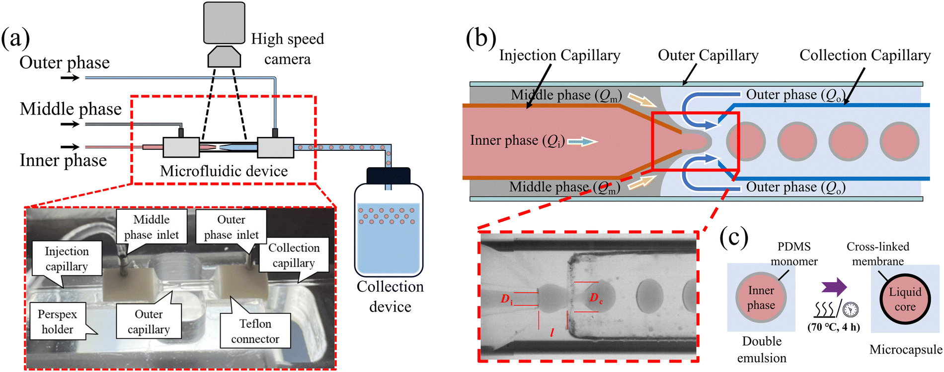 | ||
| Fig. 2 (a) Schematic diagram of the experimental setup for capsule fabrication. The inset shows a labelled photograph of the 3D nested glass capillary device mounted on a Perspex holder. (b) Schematic of the capillary device used to make water-oil-water (W/O/W) double emulsions. The optical microscope image shows the formation of double emulsion droplets in a typical dripping-flow regime (Qi = 24 μL min−1, Qm = 3 μL min−1 and Qo = 150 μL min−1 for the inner, middle and outer phases respectively). Di is the diameter of the injection capillary, Dc is the diameter of the collection capillary, and l is the distance between the two capillaries. (c) Schematic diagram of the microcapsule curing process. | ||
The nested glass capillary device shown in Fig. 2(a and b) comprised three glass capillaries of circular cross-section: injection and collection capillaries (outer diameter O.D. = 1.0 mm, inner diameter I.D. = 0.58 mm, World Precision Instruments) and an outer capillary (O.D. = 2.0 mm, I.D. = 1.8 mm, S Murray & Co, UK). The outer capillary was snapped into two pieces of approximately 2 cm length after scoring its midpoint with a ceramic tile (Sutter Instrument). The injection capillary was tapered with a micropipette puller (P-97, Sutter Instrument) and its tip was cut off and polished using the tile to a diameter of Di = 120 μm. A gas torch flame was used to melt one end of the collection capillary to form a constricted nozzle-like structure. We treated several capillaries and selected those with a nozzle diameter Dc = 350 ± 20 μm to use in the nested capillary device. The 90° bend of the collection capillary was applied to the initially straight capillary held in a horizontal position, by heating its midpoint under a gas torch flame until the heat-softened region allowed the end of the capillary to drop spontaneously under gravity.
We used a mixture of water, glycerol (Sigma Aldrich) and 2.0 wt% PVA (Polyvinyl alcohol, partially hydrolysed, MW approx. 30![[thin space (1/6-em)]](https://www.rsc.org/images/entities/char_2009.gif) 000, Sigma-Aldrich) for both inner and outer phases, where water and glycerol were mixed in 36:64 by volume. Carminic acid (Sigma-Aldrich) was added at 0.1 wt% to the inner phase to dye the capsules red. The middle phase was PDMS (Sylgard 184, Dow Corning) which could be mixed with different ratios of base to crosslinker to vary the elastic properties of the cured material. The mixture was degassed in a vacuum chamber for 20 minutes to extract dissolved air before transferring it to a 1 mm syringe (Injekt-F) to be injected with a syringe pump. Because the PDMS progressively cured over time, thus increasing its viscosity, the mixture had to be used within 3 hours to ensure stable droplet formation with consistent size and shape. To achieve water-oil-water (W/O/W) double emulsions, the injection capillary had to be chemically treated with Sigmacote (Sigma-Aldrich), a solution of chlorinated organopolysiloxane dissolved in heptane which adsorbs to the glass surface to form a hydrophobic coating. The collection and outer capillaries were treated with oxygen plasma (HPT-100, Henniker Plasma) at 100% power for 3 minutes to enhance their hydrophilicity.
000, Sigma-Aldrich) for both inner and outer phases, where water and glycerol were mixed in 36:64 by volume. Carminic acid (Sigma-Aldrich) was added at 0.1 wt% to the inner phase to dye the capsules red. The middle phase was PDMS (Sylgard 184, Dow Corning) which could be mixed with different ratios of base to crosslinker to vary the elastic properties of the cured material. The mixture was degassed in a vacuum chamber for 20 minutes to extract dissolved air before transferring it to a 1 mm syringe (Injekt-F) to be injected with a syringe pump. Because the PDMS progressively cured over time, thus increasing its viscosity, the mixture had to be used within 3 hours to ensure stable droplet formation with consistent size and shape. To achieve water-oil-water (W/O/W) double emulsions, the injection capillary had to be chemically treated with Sigmacote (Sigma-Aldrich), a solution of chlorinated organopolysiloxane dissolved in heptane which adsorbs to the glass surface to form a hydrophobic coating. The collection and outer capillaries were treated with oxygen plasma (HPT-100, Henniker Plasma) at 100% power for 3 minutes to enhance their hydrophilicity.
Immediately after plasma treatment, the injection and collection capillaries were co-axially aligned inside the larger outer capillary. The outer capillary was held between two custom-made Teflon connectors (see the inset of Fig. 2(a)) which were accurately drilled through along their central axis; see Fig. S1 in ESI† for the detailed design. The injection and collection capillaries were each pushed through a connector so that the tapered end of the injection capillary was separated from the nozzle of the collection capillary by a distance l ≃ 200 μm, as shown in Fig. 2(b). The Teflon connectors facilitated alignment of the capillaries to within 5°, which we further adjusted by eye under the microscope. Fluid inlet tubes were connected at this stage and all joints were sealed and fixed with a UV curable glue consisting of a 70:30 (v/v) mixture of pentaerythriol triacrylate (PETA, Sigma-Aldrich) and Tri(propyleneglycol) diacrylate (TRPGDA, Sigma-Aldrich) with 5% of 1-Hydroxycyclohexylphenyl ketone (Sigma-Aldrich) as the photoinitiator. This glue solidified within a few seconds under UV irradiation, which enabled rapid assembly of the device. The entire device was positioned inside a well milled in a Perspex sheet, with an observation window cut out to enable imaging of the double emulsion formation. The entire design was focused on enabling rapid and reproducible dismantling and reassembly of the device, which typically took 20 minutes if all accessories were readily available.
To generate the double emulsion, the inner and middle phases were injected with constant volumetric rates (Qi and Qm) into the injection capillary and the gap between the injection and outer capillaries through a tube into the leftmost connector, respectively. The outer phase was injected at Qo through the gap between the collection and outer capillaries through a tube into the rightmost connector (see Fig. 2(a and b)). The inner and outer phases were injected under flow rate control using a pressure controller (Elveflow Mk3+ 0–2 Bar, Elvesys) coupled to in-line Mass Flow Sensors (MFS, 0–80 μL min−1 and 0–1000 μL min−1, Elvesys). The middle phase was injected using a syringe pump (KD Scientific, Model 210) to avoid the occlusion of the flow sensors because of the eventual curing of the middle phase.
The three phases came into contact in the region of length l between the injection and the collection capillaries (Fig. 2(b)), where the inner phase coated by the middle phase broke into double emulsion droplets suspended in the outer phase. In order to achieve the interface shapes necessary for the stable generation of coated droplets, the fluids had to be introduced in strict order. We first flowed the outer phase into the system and let it wet the entire device before introducing the middle phase. A stable cone-like interface was formed owing to the hydrophobic injection capillary and the hydrophilic outer capillary, resulting in the formation of a regular train of middle phase droplets. Finally, the inner phase liquid was introduced in order for it to be completely surrounded by the middle phase upon exit of the injection capillary, and the train of middle-phase droplets was thus replaced by droplets of inner phase encapsulated by the middle phase. The flow rate for each phase was adjusted to retain a stable dripping regime, as shown in Fig. 2(b). This capillary device could make in excess of one hundred capsules per minute under optimal operating conditions. Video 1 in ESI† shows an example of double-emulsion generation under such optimal conditions. Sub-optimal conditions are shown in Video S2 (ESI†), where mixing of the inner and outer phases occurs due to the misalignment of the injection and collection capillaries; in Video S3 (ESI†) the interface breaks up due to defective hydrophobic treatment on the injection capillary; and in Video S4 (ESI†) an irregular interface forms due to insufficient plasma treatment on the outer and collection capillaries.
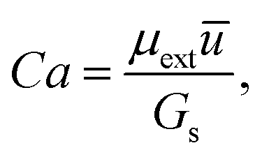
We typically generated populations of tens of thousands of coated droplets to be cured. The bottle in which they were collected contained a buffer layer of the suspending liquid (outer phase) to avoid direct contact with the bottom wall upon impact. After collection, the bottle was placed in an oven at 70 °C for 4 hours to cure the PDMS coating and convert the droplets into capsules, as illustrated in Fig. 2(c). Curing the coating while the droplets were at rest ensured uniform membranes and avoided off-centre placement of the core,28 in contrast with in situ UV-polymerisation where moving droplets are irradiated in the outlet capillary while subject to shear forces. Shrinkage of the PDMS coating by <1.5% during curing resulted in a slight extensional pre-stress being applied to the membrane. The suspensions were then flowed through a planar porous medium consisting of a suitably confined hexagonal array of cylindrical pillars in a Hele-Shaw cell (see Fig. S2(a) in ESI†). This operation filtered out the few capsule clusters (<0.5%) formed during curing by trapping them in the porous domain. Although physical and chemical properties remained stable over periods of months, regular stirring of the suspension was required to avoid capsules sticking together due to the drainage of the lubrication layer separating them. Moreover, we did not observe any plastic deformation of our capsules in flow, which means that we could reuse them multiple times over periods of months.
3 Capsule characterisation
3.1 Geometrical properties
Healthy human RBCs typically exhibit low size variability with typical dimensions of 7–8 μm,45 and thus any RBC analogue must also be highly monodisperse. Accurate control of capsule size and membrane thickness is also important to ensure reproducible experiments and meaningful upscaling from RBCs to capsules. The histogram in Fig. 3(a) shows the distribution of outer and inner capsule diameters measured from a sample of 70 capsules manufactured with Qi = 35 μL min−1, Qm = 10 μL min−1 and Qo = 300 μL min−1. Both inner and outer diameters were measured based on magnified images, where the ultra-thin membranes become quite visible, by averaging measurements over the capsule contour; see more details in S4 of ESI.† The mean outer and inner diameters are do = 373.7 ± 1.8 μm and di = 343.9 ± 1.4 μm, respectively, with very small standard deviations of 0.4% and 0.5% of the mean values, respectively. | ||
| Fig. 3 (a) Capsule diameter distribution determined from a sample of 70 PDMS capsules fabricated at Qi = 35 μL min−1, Qm = 10 μL min−1 and Qo = 300 μL min−1. (b) Relative membrane thickness 2δ/do as a function of the middle to inner phase flow rate ratio Qm/Qi. The errors correspond to the standard deviation of a sample of at least 50 capsules. The dashed line indicates the theoretical value predicted by eqn (1) based on mass conservation. The red dot indicates the membrane thickness of our red blood cell model. (c) Power-law fit of the capsule diameter (do) as a function of the flow-rate ratio Qo/(Qi + Qm). The relative membrane thickness remains constant upon changing the outer phase flow rate. The values of relative membrane thickness are: 9.14% (red circles), 5.90% (purple squares), 3.85% (blue diamonds) and 3.85% (green triangles). | ||
The capsule fabrication method also enabled us to customise the suspension by applying different flow rate combinations during double emulsion generation. The steady-state generation of double emulsions means that Qm and Qi contribute uniformly to the capsule's inner core and coating layer volumes, respectively. Thus, mass conservation, based on an incompressible spherical capsule, predicts the ratio of membrane thickness to the outer capsule radius 2δ/do that depends only on the ratio of the middle and inner phase flow rates Qm/Qi as
 | (1) |
We also found that the variation of the outer phase flow rate Qo does not affect the relative membrane thickness but will change the capsule size, which provides an opportunity to customise the capsule diameter without perturbing the relative membrane thickness. Fig. 3(c) shows that the capsule size decreases with increasing Qo, while Qm and Qi are kept fixed to maintain a constant relative membrane thickness. We were able to vary the outer capsule diameter in the range 300 μm < do < 550 μm by varying Qo. To further extend the range of capsule diameters requires the adjustment of the collection capillary diameter Dc, as discussed by Michelon et al.47 Vladisavljevic et al.48 analysed the double emulsion generation in a similar device based on mass conservation and found that the droplet diameter has a power-law dependence with an index of −1/3 to the droplet generation frequency that is directly determined by Qo. So, we also assumed a power-law relation between the capsule diameter do and Qo as
 | (2) |
3.2 Mechanical properties and flow parameters
To characterise the elastic properties of the membrane, we measured Young's modulus E by compression testing of a cylindrical sample and deduced the shear modulus theoretically in the limit of linear elasticity. Simply put, we measured the engineering stress as a function of the engineering strain, and the data is accurately captured by the Mooney–Rivlin model,49 from which we deduced E in the limit of vanishing strain. The details of this method are discussed further in S5 of ESI.† Experimental measurement of Young's modulus as a function of the mass ratio ψ of the PDMS base to the crosslinker are shown in Fig. 4. Increasing the mixing ratio from 10:1 to 40:1 decreases Young's modulus by more than an order of magnitude from 1.4 MPa to 42 kPa, compared to that of RBCs of 26 ± 7 kPa.45 For isotropic polymeric materials, the bulk shear modulus G is related to Young's modulus E via Poisson's ratio ν,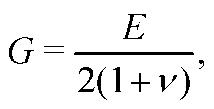 | (3) |
| Gs = Gδ, | (4) |
 | (5) |
 indicates that the resistance to bending of our capsules is negligible relative to surface shear deformation, which is consistent with RBCs (Γ = O(103), κ ≈ (1.15 ± 0.9) × 10−19 N m).45
 | ||
| Fig. 4 Young's modulus as a function of the mixing ratio ψ of PDMS base to crosslinker, obtained by fitting experimental data to the Mooney–Rivlin model.49 Each point corresponds to the mean value of five replicate measurements, and the error bars quantify deviations from the constitutive model. The dashed line shows a power-law fit of the variation of Young's modulus as a function of ψ. | ||
We also define the capillary number Ca based on the viscosity of the suspending fluid μext and the surface shear modulus Gs as
 | (6) |
Finally, the Reynolds number Re = ρūD/2μ of our tested capsule flow typically ranges from 10−8 to 10−5. For RBCs in the microcirculation, Re ∼ 10−3 to 10−1.55 In both systems, the low Re ensures inertia-less flow.
3.3 Controlled capsule deflation
With a typical surface area A ≃ 140 μm2 and volume V ≃ 100 μm3, RBCs have a large surface area to volume ratio of A/V ≃ 1.56 times that of an equivalent sphere with the same surface area because of their biconcave shape at rest. A sphere with the same surface area as the RBC would have a equivalent volume Ve ≃ 156 μm3. Thus, the reduced volume of RBCs is α = V/Ve = 0.64.9 This reduced volume can be matched in our analogue capsule model by deflating spherical capsules by 36%. We achieved capsule deflation through osmosis because the PDMS membrane is permeable to water but not to glycerol and thus, the osmotic pressure generated by a larger concentration of water inside the capsule core than in the suspending buffer solution in the collection bottle drives water across the membrane and out of the capsule until concentrations equilibrate. We started from a population of spherical capsules, a sample of which is visualised on a microscope glass slide in Fig. 5(a). Although both the inner phase, forming the core of the capsule, and the buffer solution in the bottle had the same mixing ratio of water to glycerol, the slightly lighter PDMS membrane meant that capsules spontaneously rose to the upper surface of the buffer solution in the bottle over a period of a few hours. Hence, we could easily remove the suspending liquid with a syringe and replace it with pure glycerol. The capsules were then carefully stirred into the pure glycerol with a glass bar taking utmost care to avoid trapping any air bubbles. The osmotic pressure generated by the difference in water concentration between the capsule core and pure glycerol in the bottle drove water across the membrane until the capsule core was mostly depleted of water because of the large volume of glycerol in the bottle. This process took about 30 minutes. The suspension was then left to rest for a few hours to allow the capsules to rise to the top surface again. We then repeated the process at least three times to ensure that all water in the capsule core had been removed. | ||
| Fig. 5 Capsules with different levels of deflation (characterised by the reduced volume ratio α): (a) spherical capsules after fabrication, α = 1; (b) capsules deflated by 36%, α = 0.64, corresponding to the RBC value; (c) capsules deflated by 60%, α = 0.4; (d) capsules deflated by 80%, α = 0.2. The capsules are made of PDMS and cross-linker mixed in a ratio of 40:1, and their initial diameters do = 350 ± 3 μm with a relative membrane thickness 2δ/do = 4%. | ||
By adjusting the mixing ratio of water to glycerol in the capsule core, we produced microcapsules with different levels of deflation. Fig. 5(b–d) show deflated capsules with volumes reduced by 36%, 60% and 80%, respectively. The capsules with 36% volume reduced match the reduced volume α of real RBCs. A 36:64 by volume solution of water and glycerol was used for the inner and outer phases to generate double emulsion required for these capsules.
4 Steady flow and deformation of spherical and deflated capsules in capillaries
We now compare the steady flow and deformation of spherical and deflated capsules (with a reduced volume of 0.64 identical to RBCs) in cylindrical glass capillary tubes of inner diameters D = 0.4, 0.3, 0.2 mm. The experiments were performed by injecting a very dilute suspension of capsules into a capillary tube at constant volumetric rate using a syringe pump (KD Scientific, Model 210), which ensured that the capsules were sufficiently separated to avoid measurable interaction within the tube. We used the high speed camera fitted with long-distance magnifying optics (Navitar 12× Zoom Lens System coupled with a 10× microscope objective) to capture images of the capsule shapes. Images were recorded at a frame rate between 125 to 1500 fps (depending on the flow rate) with an exposure time of 1/3000 second. The capillary tube was backlit with a powerful cold-light source (Karl Storz-Xenon Nova 300).A comparison between the spherical and deflated capsule properties is listed in Table 1. The effective diameter deff, which refers to the diameter of a sphere with the same volume as the capsules, is reduced from do = 350 ± 3 μm to approximately 302 μm upon reduction of the capsule volume by 36%. This means that the confinement parameter β = deff/D takes different values for spherical and deflated capsules in the same capillary tube. A 90:10 solution by volume of glycerol in water was used for both the suspending fluid and core of the spherical capsules, whereas pure glycerol was used for deflated capsules. Thus, there is no contrast between the viscosity of the capsule core and the suspending fluid.
| Parameters | Spherical capsules | 36% deflated capsules |
|---|---|---|
| Reduced volume ratio α | 1 | 0.64 |
| Effective diameter (deff, μm) | 350 ± 3 | 302 |
| Relative membrane thickness (2δ/do) | 4% | 4% |
| Shear elastic modulus (Gs, N m−1) | 0.098 | 0.098 |
| External viscosity (μext, Pa s) | 0.353 | 1.55 |
| Viscosity ratio (μint/μext) | 1.00 | 1.00 |
Fig. 6 shows a comparison between steady state deformation of initially spherical capsules (Fig. 6(a, d and f)) and deflated capsules (Fig. 6(b, e and g)) in each of the three capillaries. For D = 0.4 mm, both types of capsules are unconfined (β = 0.875 for spherical capsules and β = 0.755 for deflated capsules), so that they remain undeformed in the absence of flow; see panels (a-i) and (b-i) of Fig. 6. The statically spherical capsule extends as Ca increases, consistent with previous reports in the literature,38 and adopts a parachute shape seen in Fig. 6(a-iii). We quantify capsule deformation as the ratio of the maximum length of the capsule to its maximum width L/W, which is measured on a closely fitted rectangular bounding box, enclosing the imaged capsule contour, parallel to the flow direction; see an example in panel (a-iv) of Fig. 6.
 | ||
| Fig. 6 Steady shapes of spherical and deflated capsules and RBCs for different capillary numbers Ca and confinement ratios β: (a) spherical capsules, β = 0.875; (b) deflated capsules, β = 0.755; (c) RBCs in a 10 μm cylindrical silica capillary tube, β ≈ 0.6;56 (d) spherical capsules, β = 1.167; (e) deflated capsules, β = 1.007; (f) spherical capsules, β = 1.750; (g) deflated capsules, β = 1.510. The flow direction is from left to right. | ||
Fig. 7 shows that the deformation ratio L/W varies approximately linearly as a function of Ca for the initially spherical capsules (solid symbols) in all three capillaries. In contrast, the deflated capsules (open symbols) are buckled inward in the absence of confinement and flow (see Fig. 6(b-i)), due to compressive stresses in the membrane induced by the volume reduction.25 In this case, they adopt random orientations (Fig. 6(b-i)), which results in a mean value of L0/W0 ≃ 1 at Ca = 0 despite the fact that their volume is less than that of spherical capsules. RBCs also adopt random orientations at rest but their shape is biconcave. In weak flow (Fig. 6(b-ii)), these deflated capsules align with the shear flow so that their inward buckled region is situated at the rear and their shape resembles a parachute. However, they do not extend axially so that L/W remains approximately constant up to a threshold value of the capillary number Cath = 0.18 (Fig. 6(b-iii)), where the shear forces on the capsule presumably balances the compressive pre-stress of the deflated capsule. Beyond this threshold, L/W increases linearly with Ca and the capsule retains its parachute-like shape (Fig. 6(b-iv)). To the best of our knowledge, the role of pre-stress in RBCs has not been ascertained57 and the extent of deformation of RBCs at low Ca is very limited; see orange asterisks in Fig. 7. For high capillary numbers (Ca ≥ 0.32), we observed both symmetrical parachute-like and asymmetrical slipper-like shapes (Fig. 6(b-v)). This shape transition agrees well with the phase diagram of steady-state RBC morphology reported by Recktenwald et al.58 and Abkarian et al.6 Furthermore, the elongated shapes of these deflated capsules are also consistent with the deformation of RBCs in an unconfined capillary tube (D = 10 μm, β ≈ 0.6) at comparable capillary numbers Ca,56 as shown in panel (c) of Fig. 6. The values of β and Ca for RBCs are calculated in the same way as for capsules, using an effective diameter of 5.76 μm and a shear modulus of 5.5 μN m−1.45 RBCs (orange asterisks in Fig. 7) exhibit deformation ratios that are marginally smaller than the deflated capsule data for β = 0.755 (black open squares in Fig. 7) which is consistent with their smaller confinement parameter.
 | ||
| Fig. 7 Variation of the capsule deformation ratio (L/W) with Ca. The solid dots and hollow squares correspond to the spherical and deflated capsules, respectively, where the different colours indicate different capillary diameters: 0.4 mm (black), 0.3 mm (red) and 0.2 mm (blue). The error bars indicate the standard deviation of the parameters across at least 8 capsules. The dashed lines are linear fits to the data, and the solid lines are plotted to guide the eye. The orange asterisks denote relative deformation of the RBCs in a 10 μm silica capillary tube (β ≈ 0.6) taken from Lanotte et al.56 The labels refer to the capsule snapshots shown in Fig. 6. (Note the slight discrepancy in Ca with the images shown in Fig. 6(c) which are from the same paper.) The green and purple dotted lines indicate the threshold Ca of membrane rupture for spherical and deflated capsules, respectively, summarised in inset as a function of the confinement β. | ||
In capillaries with D = 0.3 mm and 0.2 mm, the spherical capsules are initially compressed into a cylindrical barrel shape with spherical end caps under tension (see panels (d-i) and (f-i) of Fig. 6), so that the static deformation ratio L0/W0 exceeds unity (Ca = 0). For increasing Ca, the capsules extend considerably in the axial direction while only marginally narrowing (Fig. 6, panels (d-ii, iii) and (f-ii)), so that the thickness of the lubrication layer between their surface and the wall of the tube remains approximately constant. We also observed axially oriented wrinkles around the circumference of the rear half of the capsule barrel (panels (d-ii, iii) and (f-ii) of Fig. 6) due to the significant lateral compression exerted on the capsule membrane, as discussed by Hu et al.59
In contrast, the deformation of deflated capsules with increasing Ca is much closer to that observed in the absence of confinement (see Fig. 6(b, e and g)). This is because the deflated capsule has excess membrane that can accommodate the increased confinement without significantly stretching its membrane axially. It follows that the threshold Cath beyond which the shear flow stretches the membrane decreases with increasing confinement β, as shown in Fig. 8(a), and we expect Cath to tend to zero for sufficiently high β. However, when β decreases below unity, Cath increases sharply.
 | ||
| Fig. 8 (a) Threshold value of Ca beyond which deflated capsules elongate, as a function of β. The dotted line is a guide to the eye. (b) Initial capsule length scaled by the tube diameter, L0/D, as a function of confinement β for β > 1. The black line indicates the theoretical values predicted by eqn (8). (c) Linear variation of the capsule elongation rate 1/λ as a function of β. The dash dotted lines are linear fits and the error bars represent fitting errors. (d) Variation of the scaled capsule elongation as a function of scaled Ca. The symbols and colours follow the same convention as in Fig. 7. | ||
Furthermore, we found that spherical capsules typically break more easily under flow than deflated capsules through rupture of their membrane. For spherical capsules which have been previously explored,60,61 we find that the threshold value of Ca for membrane rupture is always less than 0.1, as shown with a green dotted line in the inset of Fig. 7, where the vertical error bar indicates the Ca interval between intact and ruptured capsules. This suggests that the spherical capsules do not adequately model the transport of RBCs, which can sustain higher relative shear stresses and typically remain intact for Ca ≥ O(10−1).56,62 In contrast, the deflated capsules deform within the same Ca range as RBCs (see the orange asterisks in Fig. 7) and only rupture at Ca values of approximately five times the value for the spherical capsules (purple dotted line in Fig. 7). Thus, the reduced volume and excess membrane of the deflated capsules make them a useful proxy for RBCs.
The results of Fig. 7 indicate that the elongation of both spherical and deflated capsules is mainly determined by Ca and β. We propose a simple geometrical model to interpret the capsule elongation mechanics and quantify the effects of these two parameters. In the absence of flow (Ca = 0), we use geometry to predict the dependence of the static capsule shape on β. If we assume both types of capsules are spherical for unconfined geometries (β ≤ 1), the initial capsule length and width approximately match their effective diameter L0 = W0 = deff and L0/D = β. For β > 1, the capsule shape can be approximated by a cylinder with hemispherical caps at both ends (see inset schematic in Fig. 8(b)), and volume conservation implies
 | (7) |
 | (8) |
Assuming that the cylindrical barrel region of a capsule is the primary source of its membrane surface extension in flow, and neglecting capsule width reduction (W = D) at increasing Ca, the relative surface extension is given by
 | (9) |
 | (10) |
![[small gamma, Greek, dot above]](https://www.rsc.org/images/entities/char_e0a2.gif) w ∼ ū/D approximates the wall shear rate, based on the mean velocity ū and the channel diameter D, and k is a dimensionless proportionality coefficient. The stress–strain balance given by eqn (10) captures the observed linear growth of the relative capsule elongation as a function of Ca (Fig. 7) and a linear relationship between the flow-induced elongation rate (L/L0 − 1)/Ca and the confinement parameter β (Fig. 8(c)).
w ∼ ū/D approximates the wall shear rate, based on the mean velocity ū and the channel diameter D, and k is a dimensionless proportionality coefficient. The stress–strain balance given by eqn (10) captures the observed linear growth of the relative capsule elongation as a function of Ca (Fig. 7) and a linear relationship between the flow-induced elongation rate (L/L0 − 1)/Ca and the confinement parameter β (Fig. 8(c)).
Mendez and Abkarian62 rescaled the capillary number as (ϕC)−1βCa to account for non-spherical capsule shapes and membrane pre-stress, introducing ϕ, a geometric quantity characterising the capsule deflation (i.e., related to the reduced volume ratio α), and C, a non-dimensional pre-stress constant. The inverse of the parameter k in eqn (10) can therefore be interpreted as a measure of the combined effects of ϕ and C. Fig. 8(c) shows that the capsule elongation rate 1/λ = (L/L0 − 1)/(Ca − Cath), where Cath = 0 for spherical capsules, is approximately linear in β over the considered experimental range for both spherical and deflated capsules, consistent with eqn (10). A semi-empirical relation obtained by fitting the experimental data is shown in Fig. 8(c):
 | (11) |
The compressive stress associated with larger surface-to-volume ratio of the deflated capsules contributes to the smaller slope coefficient in eqn (11) compared to the spherical capsules, which corresponds to the parameter k in eqn (10).
Using eqn (11) to account for the confinement, we rescaled the excess capillary number above its threshold value, based on Cath (see Fig. 8(a)). Fig. 8(d) shows the scaled capsule elongation (engineering elongation strain) L/L0(β) − 1 as a function of the effective capillary number (Ca − Cath(β))/λ(β). Therefore, in Fig. 8(d), both spherical and deflated capsules are unstrained at zero effective capillary number. This scaling is sufficient to approximately collapse the data onto a master curve (orange line in Fig. 8(d)), which indicates that the deflated capsules exhibit similar flow-induced deformation to the spherical ones for Ca > Cath. Fig. 8(d) also highlights that the deflated capsules can reach larger maximum elongation strains than the initially spherical capsules for a wide range of flow confinements.
5 Discussion and outlook
In this paper, we have developed a 3D nested capillary microfluidic device which can robustly fabricate a large number of monodisperse PDMS microcapsules with ultra-thin and soft membranes as a physical model for RBCs. The geometrical and mechanical parameters (e.g., size, membrane thickness and membrane elasticity) of these non-ageing capsules are accurately controlled by varying the flow conditions and the composition of the membrane. This means that polydisperse suspensions of capsules of different size and/or stiffness can also be obtained by mixing populations of capsules manufactured under different flow conditions.In principle, the capsule size can be adjusted to the same order as the RBC size (less than 10 μm). To retain dominant shear deformation relative to bending the ratio of membrane thickness to capsule radius has to remain of the order of a few percents. The nested capillary device can be scaled down (although it would become more challenging to operate and might require improvements to positioning control). The fabrication of ultra-thin PDMS membranes on the order of 100 nm could be a hurdle. When we fabricated capsules with membrane thickness reduced from 7 μm to 2 μm, we could not achieve robust populations and observed systematic rupture of a small proportion of capsules. Finally, the high pressure required to perfuse high-viscosity PDMS into the much smaller nested-capillaries would add to the fabrication challenges.
We deflate our capsules using osmosis to accurately match the reduced volume of real RBCs. This enables our capsules to exhibit the large elastic deformations characteristic of RBCs in confined flow without rupturing. We compare the steady propagation of initially spherical and deflated capsules for a wide range of capillary numbers and confinement ratios. The presence of compressive stresses induced by capsule deflation delays the elongation of deflated capsules for Ca below a threshold value. Beyond this confinement-dependent threshold, capsule elongation increases approximately linearly with Ca. We show that only deflated capsules with the same reduced volume as RBCs exhibit comparable flow behaviour to RBCs over a similar range of capillary number (Ca ≥ O(10−1)). Although both spherical and deflated capsules can adopt the typical parachute-like shape of steadily propagating RBCs, symmetry-breaking into the slipper-like shape only occurs for deflated capsules at sufficiently high Ca. To our knowledge, this is the first time an experimental model has quantitatively reproduced the steady-state deformations of RBCs. However, we only considered confinement parameters β ≥ 0.8, so we did not observe the off-centred slipper-like shape of RBCs reported in the literature for lower β.6
Similar to computational models of RBCs, our capsules provide a physical model for the deformation of RBCs in flow. However, the experimental model can routinely achieve higher haematocrits (up to 50%) and larger flow domains, e.g., when studying capsule flow through disordered planar porous media, see an example in Fig. S2(b) of ESI.† We can experiment on domains which are an order of magnitude larger than previously reported numerical geometries.9 Such a model can also be advantageous compared with experimentation on real RBCs because control and robustness enable the systematic variation of parameters. However, our capsules remain idealised in that they do not exhibit the biconcave shape of RBCs,22 nor do they match the viscosity ratio between internal and external fluids and the encapsulating membrane is hyperelastic rather than viscoelastic.62 More generally, they bypass key physiological effects, such as RBC-specific membrane biochemistry, cytoskeleton effects62 and aggregation phenomena.63
Despite these simplifications, suspensions of these ultra-soft deflated capsules provide a powerful tool to explore the rheology of soft-particle suspension flows, with applications to haemodynamics and haemorheology in complex microvascular or extravascular tissues, such as the human placenta,13,64 as well as to other areas of biomedicine and industry, such as targeted drug delivery3 and enhanced oil recovery.65 In the biomimetic porous media analogues inspired by the placental microstructures (Fig. S2 in ESI†), these deflated capsules routinely flow through tiny pore-throats (100 μm) of approximately 1/3 of the effective diameter of the capsule (302 μm). This confinement level is similar to the ∼2 μm vessels or openings in the spleen,66,67 which are 1/3 of the effective diameter of the RBC.
Author contributions
AJ and IC conceived this research; QC, NS and KS conducted the experiments; QC performed initial data analysis, with contribution from all the authors; QZ supplied reference RBC data; QC wrote the manuscript, which was edited by all the authors.Conflicts of interest
There are no conflicts to declare.Acknowledgements
This work was supported by the UKRI EPSRC research grant (EP/T008725/1). QC acknowledges support by China Scholarship Council (grant No. 202006220020). QZ acknowledges support by the UKRI EPSRC grant (EP/T008806/1).Notes and references
- G. Hao, C. Yu, Y. Chen, X. Liu and Y. Chen, Int. J. Heat Mass Transfer, 2022, 190, 122738 CrossRef CAS.
- Z. Fang, X.-R. Cao, Y.-L. Yu and M. Li, Colloids Surf., A, 2019, 570, 282–292 CrossRef CAS.
- N.-D. Dinh, M. Kukumberg, A.-T. Nguyen, H. Keramati, S. Guo, D.-T. Phan, N. B. JaAfar, E. Birgersson, H. L. Leo, R. Y.-J. Huang, T. Kofidis, A. J. Rufaihah and C.-H. Chen, Lab Chip, 2020, 20, 2756–2764 RSC.
- T. Y. Lee, M. Ku, B. Kim, S. Lee, J. Yang and S.-H. Kim, Small, 2017, 13, 1700646 CrossRef PubMed.
- A. S. Mao, J.-W. Shin, S. Utech, H. Wang, O. Uzun, W. Li, M. Cooper, Y. Hu, L. Zhang, D. A. Weitz and D. J. Mooney, Nat. Mater., 2016, 16, 236–243 CrossRef PubMed.
- M. Abkarian, M. Faivre, R. Horton, K. Smistrup, C. A. Best-Popescu and H. A. Stone, Biomed. Mater., 2008, 3, 034011 CrossRef PubMed.
- A. Guckenberger, A. Kihm, T. John, C. Wagner and S. Gekle, Soft Matter, 2018, 14, 2032–2043 RSC.
- D. Barthès-Biesel, Annu. Rev. Fluid Mech., 2016, 48, 25–52 CrossRef.
- Q. Zhou, K. Schirrmann, E. Doman, Q. Chen, N. Singh, P. R. Selvaganapathy, M. O. Bernabeu, O. E. Jensen, A. Juel, I. L. Chernyavsky and T. Krüger, Interface Focus, 2022, 12, 20220037 CrossRef PubMed.
- A. N. Beris, J. S. Horner, S. Jariwala, M. J. Armstrong and N. J. Wagner, Soft Matter, 2021, 17, 10591–10613 RSC.
- J. Carneiro, R. Lima, J. B. L. M. Campos and J. M. Miranda, Soft Matter, 2021, 17, 3963–3974 RSC.
- C. G. Koch, A. I. Duncan, P. Figueroa, L. Dai, D. I. Sessler, S. M. Frank, P. M. Ness, T. Mihaljevic and E. H. Blackstone, Ann. Thorac. Surg., 2019, 107, 973–980 CrossRef PubMed.
- Q. Zhou, E. Doman, K. Schirrmann, Q. Chen, E. A. Seed, E. D. Johnstone, P. R. Selvaganapathy, A. Juel, O. E. Jensen, M. O. Bernabeu, T. Krüger and I. L. Chernyavsky, Curr. Opin. Biomed. Eng., 2022, 22, 100387 CrossRef CAS.
- A. Rubio, M. López, T. Rodrigues, L. Campo-Deaño and E. J. Vega, Soft Matter, 2022, 18, 7510–7523 RSC.
- S. H. Sadek, M. Rubio, R. Lima and E. J. Vega, Materials, 2021, 14, 2451 CrossRef CAS PubMed.
- D. Pinho, V. Carvalho, I. M. Gonçalves, S. Teixeira and R. Lima, J. Pers. Med., 2020, 10, 249 CrossRef PubMed.
- J. Lee and Y. Fung, Microvasc. Res., 1969, 1, 221–243 CrossRef CAS PubMed.
- V. Seshadri, R. Hochmuth, P. Croce and S. Sutera, Microvasc. Res., 1970, 2, 434–442 CrossRef CAS PubMed.
- C. Misbah, J. Phys.: Conf. Ser., 2012, 392, 012005 CrossRef.
- D. Bento, R. Rodrigues, V. Faustino, D. Pinho, C. Fernandes, A. Pereira, V. Garcia, J. Miranda and R. Lima, Micromachines, 2018, 9, 151 CrossRef PubMed.
- V. Puthumana, P. G. Chen, M. Leonetti, R. Lasserre and M. Jaeger, arXiv, 2022, preprint, arxiv:2209.02328.
- R. Wang and B. Fang, Math. Probl. Eng., 2012, 2012, 194953 Search PubMed.
- A. Namvar, A. J. Blanch, M. W. Dixon, O. M. S. Carmo, B. Liu, S. Tiash, O. Looker, D. Andrew, L.-J. Chan, W.-H. Tham, P. V. S. Lee, V. Rajagopal and L. Tilley, Cell. Microbiol., 2020, 23, e13270 Search PubMed.
- Q. Zhu and X. Bi, Soft Matter, 2022, 18, 964–974 RSC.
- C. Quilliet, Eur. Phys. J. E: Soft Matter Biol. Phys., 2012, 35, 48 CrossRef CAS PubMed.
- G. Coupier, A. Djellouli and C. Quilliet, Eur. Phys. J. E: Soft Matter Biol. Phys., 2019, 42, 129 CrossRef CAS PubMed.
- D. F. do Nascimento, J. A. Avendaño, A. Mehl, M. J. B. Moura, M. S. Carvalho and W. J. Duncanson, Sci. Rep., 2017, 7, 11898 CrossRef PubMed.
- Y. Hennequin, N. Pannacci, C. P. de Torres, G. Tetradis-Meris, S. Chapuliot, E. Bouchaud and P. Tabeling, Langmuir, 2009, 25, 7857–7861 CrossRef CAS PubMed.
- L. Zhang, L.-H. Cai, P. S. Lienemann, T. Rossow, I. Polenz, Q. Vallmajo-Martin, M. Ehrbar, H. Na, D. J. Mooney and D. A. Weitz, Angew. Chem., Int. Ed., 2016, 55, 13470–13474 CrossRef CAS PubMed.
- S.-H. Kim, J. W. Kim, J.-C. Cho and D. A. Weitz, Lab Chip, 2011, 11, 3162–3166 RSC.
- A. S. Utada, E. Lorenceau, D. R. Link, P. D. Kaplan, H. A. Stone and D. A. Weitz, Science, 2005, 308, 537–541 CrossRef CAS PubMed.
- M. V. Bandulasena, G. T. Vladisavljevic and B. Benyahia, J. Colloid Interface Sci., 2019, 542, 23–32 CrossRef CAS PubMed.
- M. A. Levenstein, L. A. Bawazer, C. S. M. Nally, W. J. Marchant, X. Gong, F. C. Meldrum and N. Kapur, Microfluid. Nanofluid., 2016, 20, 143 CrossRef.
- P. W. Chen, R. M. Erb and A. R. Studart, Langmuir, 2011, 28, 144–152 CrossRef PubMed.
- C.-L. Mou, Q.-Z. Deng, J.-X. Hu, L.-Y. Wang, H.-B. Deng, G. Xiao and Y. Zhan, J. Colloid Interface Sci., 2020, 569, 307–319 CrossRef CAS PubMed.
- E. Häner, M. Heil and A. Juel, J. Fluid Mech., 2019, 885, A4 CrossRef.
- C. de Loubens, J. Deschamps, G. Boedec and M. Leonetti, J. Fluid Mech., 2015, 767, R3 CrossRef.
- F. Risso, F. Collé-Paillot and M. Zagzoule, J. Fluid Mech., 2006, 547, 149–173 CrossRef CAS.
- A. Diaz and D. Barthès-Biesel, Comput. Model. Eng. Sci., 2002, 3, 321–337 Search PubMed.
- Y. Lefebvre and D. Barthès-Biesel, J. Fluid Mech., 2007, 589, 157–181 CrossRef CAS.
- M. P. Neubauer, M. Poehlmann and A. Fery, Adv. Colloid Interface Sci., 2014, 207, 65–80 CrossRef CAS PubMed.
- Y. Lefebvre, E. Leclerc, D. Barthès-Biesel, J. Walter and F. Edwards-Lévy, Phys. Fluids, 2008, 20, 123102 CrossRef.
- C. Rorai, A. Touchard, L. Zhu and L. Brandt, Eur. Phys. J. E: Soft Matter Biol. Phys., 2015, 38, 49 CrossRef PubMed.
- A. Merlo, M. Berg, P. Duru, F. Risso, Y. Davit and S. Lorthois, Soft Matter, 2022, 18, 1463–1478 RSC.
- G. Tomaiuolo, Biomicrofluidics, 2014, 8, 051501 CrossRef PubMed.
- M. Rachik, D. Barthes-Biesel, M. Carin and F. Edwards-Levy, J. Colloid Interface Sci., 2006, 301, 217–226 CrossRef CAS PubMed.
- M. Michelon, B. C. Leopércio and M. S. Carvalho, Chem. Eng. Sci., 2020, 211, 115314 CrossRef CAS.
- G. T. Vladisavljevic, H. C. Shum and D. A. Weitz, Prog. Colloid Polym. Sci., 2012, 139, 115–118 CAS.
- S. Willshaw, PhD thesis, The University of Manchester (UK), 2012.
- A. Müller, M. C. Wapler and U. Wallrabe, Soft Matter, 2019, 15, 779–784 RSC.
- D. Chapelle and K.-J. Bathe, The Finite Element Analysis of Shells - Fundamentals, Springer, Berlin, Heidelberg, 2011 Search PubMed.
- T. Chu, A.-V. Salsac, E. Leclerc, D. Barthès-Biesel, H. Wurtz and F. Edwards-Lévy, J. Colloid Interface Sci., 2011, 355, 81–88 CrossRef CAS PubMed.
- J. Gubspun, P.-Y. Gires, C. de Loubens, D. Barthès-Biesel, J. Deschamps, M. Georgelin, M. Leonetti, E. Leclerc, F. Edwards-Lévy and A.-V. Salsac, Colloid Polym. Sci., 2016, 294, 1381–1389 CrossRef CAS.
- D. A. Fedosov, M. Peltomäki and G. Gompper, Soft Matter, 2014, 10, 4258–4267 RSC.
- T. W. Secomb, Annu. Rev. Fluid Mech., 2017, 49, 443–461 CrossRef.
- L. Lanotte, G. Tomaiuolo, C. Misbah, L. Bureau and S. Guido, Biomicrofluidics, 2014, 8, 014104 CrossRef PubMed.
- L. Amoudruz, A. Economides, G. Arampatzis and P. Koumoutsakos, Biophys. J., 2023, 122, 1517–1525 CrossRef CAS PubMed.
- S. M. Recktenwald, K. Graessel, F. M. Maurer, T. John, S. Gekle and C. Wagner, Biophys. J., 2022, 121, 23–36 CrossRef CAS PubMed.
- X.-Q. Hu, A.-V. Salsac and D. Barthès-Biesel, J. Fluid Mech., 2011, 705, 176–194 CrossRef.
- M. Husmann, H. Rehage, E. Dhenin and D. Barthès-Biesel, J. Colloid Interface Sci., 2005, 282, 109–119 CrossRef CAS PubMed.
- R. Chachanidze, K. Xie, J. Lyu, M. Jaeger and M. Leonetti, J. Colloid Interface Sci., 2023, 629, 445–454 CrossRef CAS PubMed.
- S. Mendez and M. Abkarian, in Dynamics of blood cell suspensions in microflows, ed. A. Viallat and M. Abkarian, CRC Press, 2019, ch. 5, pp. 125–182 Search PubMed.
- V. Clavería, C. Wagner and P. Connes, in Dynamics of Blood Cell Suspensions in Microflows, ed. A. Viallat and M. Abkarian, CRC Press, 2019, ch. 6, pp. 183–213 Search PubMed.
- W. M. Tun, G. Poologasundarampillai, H. Bischof, G. Nye, O. N. F. King, M. Basham, Y. Tokudome, R. M. Lewis, E. D. Johnstone, P. Brownbill, M. Darrow and I. L. Chernyavsky, J. R. Soc., Interface, 2021, 18, 20210140 CrossRef CAS.
- A. Yiotis, N. K. Karadimitriou, I. Zarikos and H. Steeb, Sci. Rep., 2021, 11, 3891 CrossRef CAS PubMed.
- J. B. Freund, Phys. Fluids, 2013, 25, 110807 CrossRef.
- H. Li, L. Lu, X. Li, P. A. Buffet, M. Dao, G. E. Karniadakis and S. Suresh, Proc. Natl. Acad. Sci. U. S. A., 2018, 115, 9574–9579 CrossRef CAS PubMed.
Footnote |
| † Electronic supplementary information (ESI) available. See DOI: https://doi.org/10.1039/d3sm00208j |
| This journal is © The Royal Society of Chemistry 2023 |