 Open Access Article
Creative Commons Attribution 3.0 Unported Licence
The genesis and control of microcracks in nickel-rich cathode materials for lithium-ion batteries
Qin-Tao
Liao
ab,
Si-Jie
Guo
a,
Mu-Yao
Qi
ab,
Si-Dong
Zhang
ab,
Pei-Zhong
Ma
ab,
Jin-Yang
Li
a,
An-Min
Cao
 *ab and
Li-Jun
Wan
 *ab
*ab
aCAS Key Laboratory of Molecular Nanostructure and Nanotechnology, Beijing National Laboratory for Molecular Sciences, Institute of Chemistry, Chinese Academy of Sciences (CAS), Beijing, 100190, P. R. China. E-mail: anmin_cao@iccas.ac.cn; wanlijun@iccas.ac.cn
bUniversity of Chinese Academy of Sciences, Beijing 100049, P. R. China
First published on 22nd August 2023
Abstract
Due to the advantages of high reversible capacity and low cost, Ni-rich layered metal oxides (NROs) are considered among the most competitive cathode materials for the next generation of lithium-ion batteries (LIBs). Despite the obvious contribution to energy density from increasing Ni content, the development of NROs is inevitably challenged by the severe chemical and structural instability, especially for Ni contents higher than 80%, which were manifested by notorious chemo-mechanical problems including parasitic reactions with organic electrolytes and continuous structural failure during extended cycles, thereby leading to serious problems related to the reliability and safety of LIBs. Particularly, the formation of microcracks inside the NRO particles attributed to the uneven stress field is considered a characteristic feature, whose evolution inside the particles continues to expose new electrode–electrolyte interface, accordingly aggravating the cycle stability and jeopardizing their practical application. Herein, we update the knowledge on NRO microcracks starting with a detailed discussion on those essential factors trigging their formation, and then the crack-related failure mechanism of NRO particles was introduced to elucidate the structure–performance relationship of NRO microcracks. Different control strategies focusing on modulating the physicochemical properties both on the surface and in the bulk of NRO particles are analyzed to clarify their contribution to alleviating the adverse impact of the microcracks. We also envision future research directions toward crack-free NRO materials so that robust cathode materials with high energy density and high cycling stability could be simultaneously ensured for next-generation LIBs.
1. Introduction
Lithium-ion batteries (LIBs) are widely utilized as one of the most significant electrochemical storage devices in the field of portable applications such as electronic products and electric vehicles (EVs).1–4 However, with the rapid expansion of the energy storage industry in recent years, significant improvements to the key performance indicators of LIBs such as energy density, cost, and cycling life are required. The primary impediment to meeting this goal lies in the cathodes of LIBs, which possess relatively lower specific capacities and higher cost ratios compared to other components in LIBs.5,6 Therefore, the development of high-energy cathode materials is crucial to overcome the bottleneck hindering the larger-scale application of LIBs.Ni-rich layered metal oxides (NROs), such as Li(Ni1−x−yCoxMny)O2 (NCM) and Li(Ni1−x−yCoxAly)O2 (NCA) (1 − x − y > 0.6), have been recognized as a promising category of cathode materials for the next generation of LIBs.7,8 Firstly, NRO materials exhibit distinct advantages in terms of energy density. The main capacity of NROs originated from the redox reaction of the Ni element. The NRO materials can deliver a reversible capacity of 220 mA h g−1 at 4.3 V due to the special position of the Ni3+/Ni4+ eg energy band which enables higher utilization of lithium up to 80% in the host structure without oxygen loss.8 However, the widely reported LiCoO2 (LCO) cathode can only show a capacity of 175 mA h g−1 even at a cut-off voltage of 4.45 V.9 The high specific capacity and operation voltage of NROs enable them to achieve a high energy density. Second, NROs are more cost-effective than LCO due to the substitution of more costly cobalt with comparatively cheaper nickel within the materials.10–12 In this regard, NROs can satisfy the demand for high energy density and low-cost cathodes in EVs and are emerging as a research hotspot in the field.
Despite the obvious advantages observed in NROs, their development is challenged by chemical and structural instability, especially for those with Ni contents higher than 80%, which has led to serious concerns about the reliability and safety issues of NRO-based LIBs.13 Numerous research efforts have been directed to the investigation of the failure mechanism of NROs during the electrochemical process, which identified that different factors as detailed below contributed to the performance degradation of NROs. The first is the chemical degradation caused by parasitic reactions. During the charge process, a majority of Ni cations are oxidized to highly reactive Ni4+. The interaction between formed Ni4+ and organic electrolyte will trigger the dissolution of transition metal ions (TMs) and gas evolution, leading to an increase in the surface charge transfer resistance and consequent deterioration in battery performance.14,15 Secondly, NROs will experience structural degradation resulting from the phase transition. Due to the unstable structure in the highly delithiated state particularly under high cut-off voltage (>4.7 V), the NRO materials would undergo a transition from a layered to a spine or rock-salt structure, accompanied by oxygen evolution.16 The formed rock-salt phase is electrochemically inert and impedes the diffusion of Li+, resulting in an increase in electrode polarization that limits the rate capability in NROs.17 More seriously, the large lattice mismatch between the surface rock-salt layer and bulk layered structure would trigger the formation of interfacial lattice strain, impeding the extraction of Li+ ions and contributing to capacity loss.18 Thirdly, the internal strain arising from the anisotropic lattice volume change of NROs can lead to serious mechanical degradation that undermines the structural integrity of materials and accelerates capacity loss.19 It should be noted that these factors will interweave together and put the NRO cathode particles at a high risk of chemo-mechanical failure, among which the emergence of microcracks existed as a characteristic feature. Once the cracks are formed inside the particles, they would decrease the contact areas of active materials impacting the electrical and ionic conductivity, and even isolating particles in the core, which reduces the utilization of active materials and specific capacities.20,21 Meanwhile, the occurrence of microcracks exacerbates the deleterious effect of other failure factors. For example, cracks provide channels for the infiltration of electrolyte into the interior particles, exposing fresh surfaces without protection and worsening side effects associated with the reaction at the electrode–electrolyte interface.22–24 Therefore, the presence of microcracks within NRO particles has emerged as a significant performance indicator for batteries and it is imperative to gain an in-depth insight into this phenomenon for the further advancement in NRO cathode materials.
This paper aims to provide an update on the latest progress regarding microcracks in NROs to enhance understanding of this issue owing to the rapid advancement in the research field. The generation of microcracks is attributed to the uneven stress field within the NRO particles, so we first discuss the origin of the local stress accumulation and corresponding crack formation mechanism, including the intrinsic properties of NROs and external operating conditions. Next, we analyze the failure mechanism associated with the cracks which not only impairs the charge conductivity and electrode–electrolyte interface but also aggravates their synchronous propagation between particles. These elucidate the interplay among the microcracks, structure, and electrochemical performance within NRO particles. Then, we summarize various modulating strategies that could alleviate the adverse effects of microcracks by adjusting the physicochemical properties of NRO particles including surface and bulk characteristics. The surface modification for regulating either the particle surface or grain boundaries can effectively enhance the electrode–electrolyte interface while the control on the bulk by element doping or the concentration gradient structure microstructure could delay the irreversible phase transition. The ultimate aim of these strategies is to eliminate the internal strain and avoid the appearance of microcracks. Finally, we also provide forward future research directions for a better understanding of the microcracks and the design of crack-free NRO materials (Fig. 1).
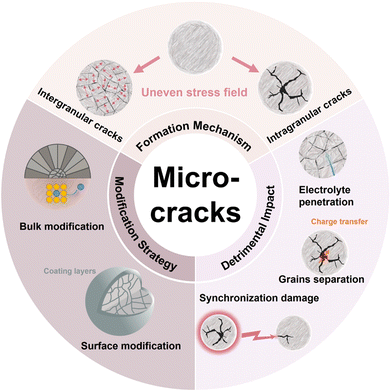 | ||
| Fig. 1 Schematic diagram of the formation, detrimental impacts of microcracks, and the corresponding modification strategy. | ||
2. The formation mechanism of microcracks
The NROs can be divided into two categories, polycrystalline cathode materials and single-crystalline ones, in terms of their morphologies. The former typically exist as near-spherical secondary microparticles composed of submicron primary components aggregated together through van der Waals force; in contrast, the latter are micronized particles nearly free from grain boundaries.25 In general, microcracks in NRO particles can be divided into two groups, intergranular cracks located at the grain boundaries and intragranular cracks occurring within primary particles. The formation of these two kinds of microcracks is attributed to an uneven stress field in materials. Local stress between primary particles results in grain boundary fracture which induces the emergence of intergranular cracks while internal stress within the grains evokes the occurrence of intragranular cracks.26 Accordingly, the polycrystalline NRO materials will show mainly intergranular cracks arising from the weakly connected grain boundary, whereas intraparticle ones dominated the single-crystalline ones due to the scarcely existing grain boundaries in this sample.27,28 Considering the complexity among grains, we will first focus on the origin of the stress within the individual particle and subsequently introduce interaction between primary particles to gain a better understanding of the underlying causes of intragranular and intergranular cracks.2.1 Intragranular cracks
The formation of intragranular cracks is attributed to local stress accumulation within the primary particles resulting from Li+ inhomogeneity distribution and structural defects. The intragranular cracks have a great impact on the performance degradation and structural damage of NRO materials, which not only reduce the contact of active materials but also provide a chance for the penetration of organic electrolyte into the inner core, subsequently aggravating severe side reactions at the electrolyte/electrode interface.The variation of Li+ content in different locations can significantly impact the lattice parameter, inducing the generation of internal stress within particles. At the location where the Li+ ions are partially extracted, the electrostatic shield effect weakens, and the repulsive force between the adjacent O layer enhances, leading to the increment of both the spacing of the Li slab and the value of the lattice parameter c. It should be noted that the lattice structure can collapse with further extraction of Li+, manifesting an abrupt drop in the value of parameter c. Ryu et al.29 investigated the structural inhomogeneity in a charged LiNi0.9Co0.05Mn0.05O2 (S-NCM90) thin section by focused ion beam (FIB) and transmission electron microscopy (TEM). Through analyzing a series of electron diffraction patterns obtained from different locations along the scan line, ranging from near the surface (i) to the center (ii) (Fig. 2a), they calculated the value of lattice parameter c in the dotted circles. The results suggested that from the surface to the bulk, the value of parameter c increased from 13.7 Å to 14.1 Å (Fig. 2b), confirming the nonuniform distribution of Li+. The inconsistency of lattice parameter c across different locations weakened the structure of the cathode and generated internal stress within the materials. By employing the finite element method, Zhang et al.30 constructed a diffusion-induced model to investigate the relationship between the Li+ distribution inhomogeneity and the stress field within the particle as depicted in Fig. 2d. Their finding revealed that the non-uniform Li+ distribution induced tensile strain, thereby promoting the generation of spatial high-stress concentration gradients. With the increase in the cycle number, the exacerbated strain contributed to the development of intragranular cracks, as evidenced by the scanning electron microscopy (SEM) image depicted in Fig. 2c.
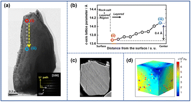 | ||
| Fig. 2 (a) TEM image of charged LiNi0.9Co0.05Mn0.05O2 (S-NCM90) cathode particles.29 (b) The lattice parameter c at various locations along the dashed yellow line in (a).29 (c) Cross-sectional SEM image of cycled S-NCM90.29 Reproduced with permission. Copyright © 2021, American Chemical Society. (d) Equivalent strain distribution inside the NCM particles caused by inhomogeneous Li+ distribution.30 Reproduced with permission. Copyright © 2020, Springer Nature. | ||
The phase mismatch between the layered structure and the rock-salt structure can also result in the presence of intragranular cracks. During the cycling process, the layered phase endures repeated volume contraction and expansion owing to the extraction and insertion of Li+. However, due to the electrochemically inactive nature, the lattice volume of the rock-salt phase adjacent to the layered phase remains unchanged. The mismatch between the two phases triggers tensile strain on the fragile rock-salt platelet. Once the accumulated stress exceeds the limits of fragile rock-salt phases, it can fracture and eventually form intragranular cracks in NRO particles.18 Lin et al.33 further investigated the intragranular cracks that arise from the phase mismatch and divided the crack growth into three stages as depicted in Fig. 3a and b. In the first stage, as Ni2+ ions migrate to the Li layers, a white line denoted by the blue arrow with serial number “1” appeared (Fig. 3b). The scanning transmission electron microscopy high-angle annular dark-field (STEM-HADDF) image (Fig. 3c) revealed that the increased distance between the adjacent (003) planes in the lattice induced deformation in the region and uneven stress distribution within the lattice. Additionally, the presence of a Ni-rich rock-salt phase was observed within the white line area (Fig. 3d). In the subsequent stage, as more Ni2+ occupied the Li+ site, the mismatch of lattice parameters between the two phases became increasingly severe, leading to elevated tensile stress and lattice distortion of the lattice. This phenomenon could be considered the appearance of a premature intragranular crack. At the final stage, the growing electrostatic repulsion at the edges of the crack caused by the increased number of Ni2+ ions in the Li layers further tore the structure and facilitated the propagation of the intragranular crack.
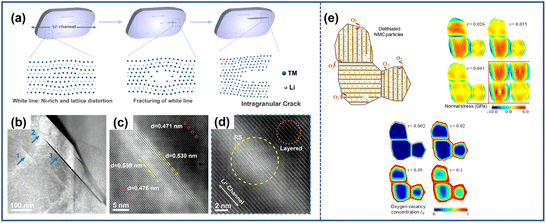 | ||
| Fig. 3 (a) Schematic illustration of the formation and development mechanism of the intragranular crack.33 (b) Low magnification STEM-HAADF image of LiNi0.8Co0.1Mn0.1O2 (NCM811), with the blue arrows here indicating the different stages of the intragranular crack of (a).33 High-resolution (c) and atomic-resolution (d) STEM-HAADF images of the white line area in (b) (denoted by arrow 1).33 Reproduced with permission. Copyright © 2020, Elsevier. (e) Finite element model of oxygen release, oxygen vacancy concentration, and crack propagation within LiNi0.6Co0.2Mn0.2O2 (NCM622).34 Reproduced with permission. Copyright © 2018, American Chemical Society. | ||
The emergence of oxygen vacancies also contributes to the formation of intragranular cracks. During the charging and discharging process, particularly under high-voltage or high-temperature operating conditions, the formation of a Li-deficient NiO-like phase often occurs along with oxygen release. Correspondingly, oxygen vacancies appear in the lattice structure, which can accelerate the formation of intragranular cracks.35,36 By using the finite element method, Mu et al.34 constructed a model to study the effect of oxygen vacancies through finite element modeling. As shown in Fig. 3e, the phase transition was easier to appear near the surface of particles accompanied by oxygen release, which resulted in a concentration difference of oxygen vacancies in the cathode particles. Therefore, the near-surface area with more oxygen vacancies experienced larger compressive stress due to the lattice expansion while the tensile stress would accelerate the fracture at the center of NRO particles.
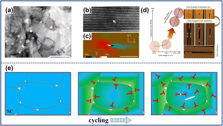 | ||
| Fig. 4 (a) Dislocations in pristine LiNi1/3Co1/3Mn1/3O2 (NCM333).26 (b) and (c) HAADF image of dislocations in pristine NCM333 and corresponding stain map.26 (d) Schematic illustration of the formation and propagation mechanisms of intragranular cracks.26 Reproduced with permission. Copyright © 2017, Springer Nature. (e) Schematic illustration of the formation mechanism of intragranular cracks resulting from the dislocation annihilation.37 Reproduced with permission. Copyright © 2020, American Chemical Society. | ||
2.2 Intergranular cracks
For the polycrystalline NROs, during the Li+ extraction/insertion process, the secondary particles may fracture along the grain boundaries due to the uneven strain caused by the anisotropic expansion and contraction of primary particles. This phenomenon leads to the formation of intergranular cracks, as illustrated in Fig. 5a.13 The change in lattice volume can be attributed to several factors, including the anisotropic change of the lattice parameter, the H2–H3 phase transition, and working conditions.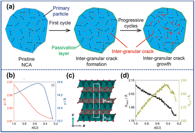 | ||
| Fig. 5 (a) Schematic illustration of the formation mechanism of intergranular cracks.20 Reproduced with permission. Copyright © 2021, American Chemical Society. (b) The evolution of lattice parameters a and c during cycling.38 (c) The crystal structure of NCM811: TM–O layers (gray), Li layers (green), and the unit cell (white rectangle).38 (d) The changes in the height of the TM–O slab (hTM–O) and Li–O slab (hLi–O) with Li+ content during charging.38 Reproduced with permission. Copyright © 2017, American Chemical Society. | ||
The change of lattice parameter a can be attributed to the oxidation of the transition metal ions and the concomitant decrease in the ionic radii of TMs. However, the variations of parameter c are somewhat peculiar.42 Kondrakov et al.38 further investigate the change in parameter c based on NCM811 using different techniques. They found that the changes in lattice parameter c depend on the height of the Li–O slab and TM–O slab (Fig. 5c), which are denoted as hLi–O and hTM–O. As shown in Fig. 5d, during the charging process, the length of the TM–O slab decreases with the deintercalation of Li+. This phenomenon can be attributed to the appearance of Ni with higher valences and stronger attraction to O because of charge compensation. The value of hLi–O initially increases from 2.639 to 2.899 Å due to the stronger repulsion between the oxygen planes with the extraction of Li+. However, when the Li+ content in this framework is less than 50%, there is a significant difference in the variation of hLi–O. In NROs, the O 2p and TM 3d orbitals are highly hybridized so that the electrons can be extracted from both the TM and O states during the charge process.43 In this regard, a deep delithiation process makes it possible to cause a reduction of the negative charge on oxygen atoms, thereby leading to a decrease in their repulsion and hLi–O.42 Once the charge on the oxygen atoms is depleted to a critical point, the lattice structure would collapse, resulting in a sharp drop in the value of hLi–O.42,44 It can be observed that the trend of hLi–O and hTM–O is different at the initial stage of charging and the extent of expansion of the Li–O slab is greater, leading to an increase in the parameter c-axis. However, in the later stage of the charging process, the reduction of both hLi–O and hTM–O leads to a decrease in the c-axis parameter. The lattice parameters of NROs would change inconsistently during the charging and discharging process, as shown in Fig. 5b.38
During the charging process, the extraction of Li+ causes the Ni-based oxide cathode material especially the NRO materials undergo a series of phase transitions that occur in three single-phase regions namely rhombohedral phase H1, monoclinic phase M, and rhombohedral phase H2 before transferring to the rhombohedral phase H3.47–49 The profile of differential capacity vs. voltage can be exploited to investigate phase transition during cycling in which each transformation redox peak represents a phase transition. As shown in Fig. 6a, higher upper cut-off voltage resulted in more apparent redox peaks. Similarly, Sun et al.41 studied the effect of phase transition on the change of parameter c. LiNi0.90Co0.05Mn0.05 (NCM900505) showed a redox peak from phase H2 to phase H3 beginning around 4.1 V while the LiNi0.60Co0.20Mn0.20O2 (NCM622) cathode did not display such a transformation oxidation peak, as shown in the dQ dV−1 curve in Fig. 6b.41 Based on the ex situ X-ray diffraction results, the parameter c values of both cathodes charged to different cut-off voltages at 4.1, 4.2, and 4.3 V were calculated and are presented in Fig. 6c. The c-axis parameters of the two materials at 4.1 V were nearly equal. However, when the voltage was raised to 4.3 V with the appearance of H2–H3 phase transition, the value of parameter c in NCM900505 decreased suddenly and faster compared to NCM622. The abrupt reduction of lattice parameter c would result in a sharp volume shrinkage of the unit cell, undermining the stability and mechanical integrity of the lattice structure by generating a local stress field, finally forming microcracks along the grain boundaries.
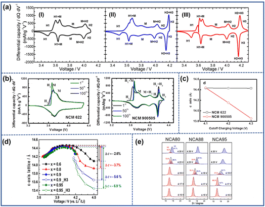 | ||
| Fig. 6 (a) Differential capacity vs. voltage curves of LiNiO2 during the first cycle at various upper cutoff voltages: (I) 4.1 V, (II) 4.2 V, and (III) 4.3 V.47 Reproduced with permission. Copyright © 2017, American Chemical Society. (b) Differential capacity vs. voltage curves of NCM622 and NCM900505.41 (c) The evolution of lattice parameter c for NCM622 and NCM900505 at various cutoff voltages.41 Reproduced with permission. Copyright © 2017, American Chemical Society. (d) The variation of lattice parameter c in Li(NixCoyMn1−x−y)O2 (x = 0.6, 0.8, 0.9, and 0.95) with charge voltage.13 Reproduced with permission. Copyright © 2018, American Chemical Society. (e) The coexistence phase ratio of H2 and H3 in (003) peaks during the initial charging of NCA80, NCA88, and NCA95.50 Reproduced with permission. Copyright © 2019, American Chemical Society. | ||
Ryu et al.13 studied the correlation between the Ni content and the H2–H3 phase transition. They compared the dQ dV−1 profiles and parameter c value of different LiNixCoyMn1−x−yO2 (x = 0.6, 0.8, 0.9, and 0.95) during the cycling process. Their results revealed that only the cathodes with the content of Ni over 80% endured the H2–H3 phase transition during the charging process. Moreover, as the proportion of Ni in the cathodes increased, the height of the redox peak representing the H2–H3 phase transition increased gradually indicating the elevated intensity of phase transition and its severer negative effect on the cathode. Therefore, LiNi0.95Co0.025Mn0.025O2 presented the largest variation of parameter c (Fig. 6d). Nam et al.50 also discovered that the onset voltage and the rate of H2–H3 phase transition also are dependent on the Ni content. As shown in Fig. 6e, the H3 phase in LiNi0.95Co0.04Al0.01(NCA95) emerged around 4.17 V earlier than other electrodes and the total phase transition ended before 4.23 V indicating a faster transition rate compared to the other electrode materials.
Watanabe et al.51 discussed the influence of DOD ranges on cracks. They tested the electrode with two DOD conditions, in which one is in the voltage range from 2.5–4.2 V denoted as 0–100% DOD, and the other is in the range of 3.48–4.05 V denoted as 10–70% DOD. During the cycling, the cell with 0–100% DOD shows poorer capacity retention and more cracks in the cathode particles while there are few microcracks in the latter even after 5000 cycles at 60 °C. This difference was attributed to the increasing extent of lattice volume changes and subsequently stronger local stress caused by the larger ΔDOD.
Park et al.52 found that not only the range but also the limit of DOD has an effect on the formation of microcracks specifically for the cathode with the content of Ni above 80%. This result was verified by comparing the NCA95 cathode cycling under different DOD conditions: upper 60% DOD (3.76–4.3 V), lower 60% DOD (2.7–4.0 V), and 100% DOD (2.7–4.3 V). From the cross-sectional SEM images captured at different DOD (Fig. 7a), it is clear that microcracks emerged as the primary particles shrink during the charging process while the microstructure was repaired with the intercalation of Li+. Furthermore, it was evident that the upper DOD limit determined the extent of the cracks, and the lower DOD limit affected the degree of recovery. Therefore, as depicted in Fig. 7b, compared with the electrode cycling at 100% DOD, the NCA95 cathode cycling at a lower DOD of 60% exhibited improved cycling stability due to the formation of fewer microcracks. This was achieved by avoiding abrupt lattice parameter change by the H2–H3 phase transition. In contrast, when cycling at an upper DOD of 60%, it showed fast capacity fading owing to the incomplete recovery during the discharge.
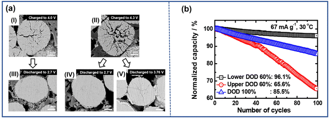 | ||
| Fig. 7 (a) Cross-sectional SEM images of NCA95 cathodes in different DOD ranges during the first cycle: (I) charged to 4.0 V, (II) discharged from 4.0 V to 2.7 V, (III) charged to 4.3 V, (IV) discharged from 4.3 V to 2.7 V, and (V) discharged from 4.3 V to 3.76 V.52 (b) Electrochemical performance of NCA95 in different DOD ranges.52 Reproduced with permission. Copyright © 2019, American Chemical Society. | ||
The generation of microcracks is not directly determined by the depth of discharge; instead, it can be achieved by controlling the change of the lattice parameter.53 Limiting the depth of charge can effectively suppress the occurrence of microcracks in the electrode. However, this approach can compromise the discharge capacity of the cell, which is not desirable for commercial applications.
3. The failure mechanism induced by microcracks
The formation of microcracks facilitates the penetration of organic electrolyte into the inner core of particles and expedites ion transportation, thereby enhancing the rate performance. However, the limited benefit cannot trade off the damage to the electrodes. First, the infiltration of electrolyte into cathode particles inside through those microcracks provides a large number of reaction sites for parasitic reactions that degrade the structure of electrode materials. Second, the microcracks compromise the mechanical integrity of cathode materials and result in the fracture of NRO particles, eventually presenting as capacity loss of assembled cells. Finally, the NRO particles with cracks could induce the propagation of cracks to neighboring intact particles.3.1 Electrolyte penetration
Microcracks that extend to the surface of the particle provide the pathway for penetration of electrolyte into the bulk of cathode particles. Watanabe et al.51 conducted an investigation on LiAl0.10Ni0.76Co0.14O2 after 350 cycles to observe the distribution of elements such as F and C, which are related to the organic liquid electrolyte containing LiPF6, dimethyl carbonate (DMC), and ethylene carbonate (EC). As depicted in energy-dispersive X-ray spectrometry (EDS) mapping (Fig. 8a), the elements C and F are distributed along with microcracks in the cathode particle bulk that provided evidence of electrolyte invasion. The organic electrolyte in the inner core of NRO particles can react with the cathode, leading to the irreversible phase transition and dissolution of transition metal ions.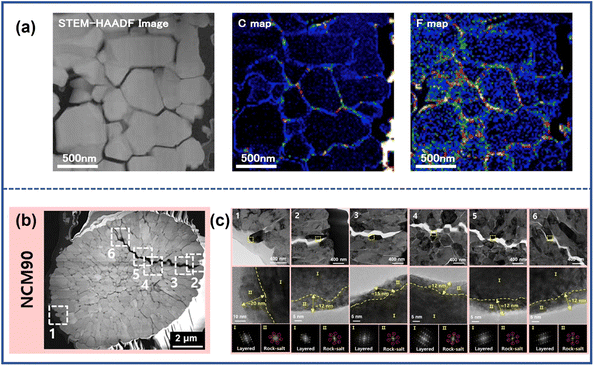 | ||
| Fig. 8 (a) HAADF-STEM image of the cycled cathode and corresponding energy-dispersive X-ray spectrometry (EDS) mapping of C and F atoms.51 (b) Dark-field STEM images of discharged NCM90.55 Reproduced with permission. Copyright © 2014, Elsevier. (c) Magnified TEM images from various locations in (b) and high-resolution TEM images of the yellow dotted rectangle, along with FFT patterns of Region I and Region II.55 Reproduced with permission. Copyright © 2022, American Chemical Society. | ||
The parasitic reaction between the electrode and electrolyte would cause the transformation of the electrode structure from the layered structure to the spinel structure, and ultimately to the rock-salt structure. During the charging process, Ni2+/Ni3+ can be oxidized to extremely unstable Ni4+, which is easily reduced to form Ni2+ by a parasitic reaction with the electrolyte. Taking the commonly used organic electrolyte ethylene carbonate (EC) as an example, the redox reaction between the cathode materials and organic electrolyte can be illustrated as follows:54
| Li0.5TMO2 + 1/10C3H4O3 → 1/2 LiTMO2 + 1/2 TMO + 3/10 CO2 + 1/5H2O |
Park et al.55 investigated the degradation of the inferior surface in different locations along with the crack propagating in the cathode particle, from the outside part of the NCM90 secondary particle to the center (point 2 → 6 in Fig. 8b). The TEM images and corresponding fast Fourier transform (FFT) patterns revealed the presence of rock-salt phase layers with thicknesses of about 12–15 nm appearing in all locations due to reaction with electrolyte (Fig. 8c). The NiO-like phase in the cathode materials blocks the pathway of Li+, thus leading to increased impedance and capacity loss.6,56
The side reaction related to the organic electrolyte can also bring about the dissolution of transition metal ions such as Ni, Mn, and Co, which can cause the premature failure of LIBs.23 During the cycling, the trace H2O in electrolyte solvents can react with the solute LiPF6, yielding acidic species:17,57
| LiPF6 + H2O → LiF + 2HF + POF3 |
The formed HF can corrode the surface structure of cathodes and initiate the dissolution of transition metal ions. The more transition metal ions are dissolved, the more serious the collapse of the cathode material structure. Meanwhile, the dissolved metal ions pass through the separator and then electrochemically deposit on the anode during the cycling. It causes the decomposition of the original SEI layers and induces the formation of a new solid electrolyte interphase (SEI) with porous and inhomogeneous structures which block the diffusion of Li+ and accelerate the appearance of lithium dendrites, decreasing the cycling life of cells.58,59
3.2 Grain separation
The grain separation of cathode particles that is provoked by microcracks can act as barriers to impede charge transfer and increase impedance within the cathode material. Additionally, as the extent of separation increases, some particles may become isolated and no longer contribute to the capacity during the cycling process.Due to the presence of microcracks, the original infusion pathway of electrons becomes more circuitous which increases impedance.64 Xia et al.60 exploited a reconstructed 3D volume model of a selected NMC particle to demonstrate the impact of cracks on electron diffusion. In Fig. 9a, the green arrow represented the original pathways of charge transfer in uncycled cathodes, while the red arrow signified the geometrically optimal pathways observed in cycled materials. By comparing the two pathways, it is evident that the presence of microcracks increases the diffusion distance for charge transfer. Besli et al.61 also demonstrated that the microcracks could impede Li+ diffusion within the particles as illustrated in Fig. 9b, which directly transformed into the increased electrical resistance during the charging/discharging process. Park et al.62 analyzed the effect of cracks on the resistance by employing scanning spreading resistance microscopy (SSRM). They found that the presence of microcracks brought about the uneven distribution of resistance within the particles, and the maximum resistance magnitude could be increased by two orders of magnitude from 10−5 to 10−7 as illustrated in Fig. 9c–e. The variation in resistance directly affected the extraction/insertion process of Li+, inducing incomplete reactions in certain regions of the cathode particles. This incomplete reaction results in a gradient distribution of Li+ content within the particles, which further accelerates the propagation of microcracks.20 With the continuous evolution of cracks, some of the grains lose complete contact with other ones. Miller et al.63 investigated the separation of grains in a single particle of LiNi0.8Co0.15Al0.05O2. In Fig. 9g and h, it can be observed that a significant portion of the particles became separated from the bulk, as the cycle number increased. These isolated parts became electrically inactive and no longer contributed to the capacity during cycling.
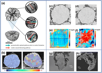 | ||
| Fig. 9 (a) Schematic diagram of the impact of cracks on the charge transfer pathway.60 Reproduced with permission. Copyright © 2018 Elsevier. (b) Diffusion deterrent of pristine and cycled NCA particles.61 Reproduced with permission. Copyright © 2021, American Chemical Society. Cross-sectional SEM images of the pristine NCA particle (c) and cycled particle (d).62 (e) Resistance images of the pristine NCA particle (e) and cycled particle (f).62 Reproduced with permission. Copyright © 2018 Elsevier. SEM images of the pristine NCA particle (g) and cycled NCA particles (h).63 Reproduced with permission. Copyright © 2013 WILEY-VCH. | ||
3.3 Synchronization damage in adjacent particles
The cracked particles can induce the formation of microcracks in surrounding particles. Due to the variation in the local conductive network, NRO particles undergo distinct electrochemical evolution during the cycling process, which leads to a heterogeneous reaction.65,66 As a result, some particles have more microcracks while others have fewer, as shown in Fig. 10a.51 However, the heterogeneity can be mitigated and reach a dynamic equilibrium due to the simultaneous driving force, which leads to the synchronization of particle damage in electrodes and the propagation of microcracks between particles.67,68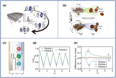 | ||
| Fig. 10 (a) The depiction of the cathode and particles with varying degrees of damage, along with the corresponding probability distribution.68 (b) The spatial distribution of damaged particles after 10 and 50 cycles.68 (c) Schematic illustrations of the composite model during the charging process in the battery.68 (d) Normalized Li concentration profiles for the normalized time t/τ, where t and τ represent the real-time and theoretical time to reach the full capacity, respectively.68 (e) Each particle's deviation from the mean damage profile (the black dashed line).68 Reproduced with permission. Copyright © 2022, American Association for the Advancement of Science. | ||
Li et al.68 investigated such dynamic evolution by exploiting LiNi0.8Co0.1Mn0.1O2 as the raw material. Fig. 10b shows that the distance between damaged particles would be shorter with the increased cycled numbers as shown in Fig. 10b, which indicated a synchronization effect inside the electrodes. Then, they constructed a theoretical model to understand such phenomena through finite element analysis. As shown in Fig. 10c, there were three neighbored particles in contact with porous carbon/binder (CB) domains of different conductivity representing that each particle had dissimilar electrochemical activity and reaction rates at the beginning of cycling. The particles attached to the high-conductivity CBs had higher reaction activity and would experience a deeper depth of charge (Fig. 10d); however, they would also confront severe mechanical damage and the formation of microcracks firstly which undermined their reactivity for the increasing electronic resistance (Fig. 10e). At that time, the adjacent particle with less destruction would replace the role of the destroyed one to participate more in the charge and discharge cycling because of its relatively higher electrochemical activity which induced the occurrence of cracks and continue the as-mentioned process again. After a repeated charging and discharging process, the damage level tended to be the same for all particles for such synchronous effects which also facilitated the propagation of microcracks among adjacent particles.
4. Strategies to suppress microcracks
The above discussions have identified that local strain accumulation caused by either uneven Li+ distribution or anisotropic lattice volume change is the main reason for the occurrence of cracks, which leads to aggravated side reactions between NROs and electrolyte, thereby easily forming more microcracks, thus leading to continuous performance degradation. Accordingly, it becomes a long pursuit to prepare cathode materials to diminish the formation of microcracks and prevent their damage to cycling stability. Two different control strategies have been effectively applied to remove the obstacle for achieving this goal. The first one is related to the coating treatment either around the particle surface or right on the grain boundary. Such a modification provides an effective barrier to prevent the parasitic reactions between the electrolyte and the cathode materials. Specifically, certain coating materials can also serve as mixed-conductive materials and enhance the electronic and ionic conductivity, which is helpful to eliminate the uneven distribution of Li+. The second approach involves bulk modification, which focuses on controlling the composition or structure of the particles' bulk phase. This can be achieved through methods such as element doping or constructing a concentration gradient structure. The former can alleviate anisotropic parameter variation by introducing heteroatoms into the bulk phase while the former can maximize the discharge capacity and stabilize the structure at the same time by changing the compositional distribution. The change in composition may lead to alterations in the microstructure of the particles, enabling the grains to grow along a specific direction. Primary particles with such a special crystallographic texture can partially relieve the local stress accumulation, thereby suppressing the formation of microcracks.4.1 Surface modification
The presence of microcracks provides pathways for the electrolyte to penetrate the inner region of the particle, leading to electrode corrosion and further crack propagation, thereby accelerating capacity fading. Considering that the electrode–electrolyte interface is favored for the occurrence of side parasitic reactions, it is crucial to improve surface stability.The coating method is a widely employed strategy to modify the surface of materials and mitigate the formation of cracks by creating protective shells on the outmost layer of cathode particles.9,73–75 The coating layer serves as a protective barrier, preventing direct contact between the electrode and electrolyte, thereby impeding the side reactions and the subsequent dissolution of transition metal ions. Nonconductive materials represented by metal oxides such as WO3, ZrO2, V2O5, MgO, and Al2O3 are the most common coating layers to improve the stability of NRO materials.76–80 These coating materials can effectively decrease the electrode–electrolyte contact area, stabilize the surface structure, inhibit the side reaction, and improve the electrochemical performance. Yao et al.76 performed an in situ construction of a homogeneous ZrO2 coating layer on the surface of LiNi0.6Co0.2Mn0.2O2. With the benefit of the uniform coating layer, the electrode could retain structural integrity after 100 cycles.
The electronically inactive materials can effectively protect the cathode surface, but during high-rate cycling their insulating properties cannot alleviate uneven Li+ distribution and subsequent local stress accumulation within the particles, causing microcrack formation and battery performance degradation.81 Therefore, the research on the coating layers with special functions is becoming a hotspot. Conductive materials such as LiAlF4, Li2MoO4, and LiF3 can not only protect the surface structure of cathodes but also improve the conductivity of NROs.82–85 In the study conducted by Fan et al.,69 a sodium-super-ion-conductor-type (NASICON-type) Li1.4Y0.4Ti1.6(PO4)3 (LYTP) ion/electron conductive coating layer was applied on the surface of LiNi0.88Co0.09Mn0.03O2 (SC-NCM88) particles, as illustrated on Fig. 11a. The coating materials demonstrated high ion conductivity, facilitating the Li+ transport on the cathode surface. Meanwhile, the interconnected LYTP framework between the particles also improved the electron conductivity. As a result, the ionic conductivity and electron conductivity of cathodes were roughly 1.5 times and 1.3 times higher than those of the original cathode respectively (Fig. 11b and c). Therefore, the modified samples exhibited a capacity of 130 mA h g−1 even after undergoing 500 cycles at a rate of 5C. In addition, some coating materials can offer additional benefits apart from enhanced ion and electron conductivity. Wang et al.86 found that a lithium and oxygen dual-ion conductor (perovskite La4NiLiO8) protective layer not only could facilitate Li+ diffusion kinetics and electronic conductivity on the particle surface but also limited the reaction activity of surface lattice oxygen by leveraging the stable oxygen vacancies/interstitials which would suppress the oxygen release as well as the irreversible phase transition, thereby alleviating the number of microcracks and boosting the cycling stability of electrodes.
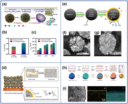 | ||
| Fig. 11 (a) Schematic illustration of the synthesis process of the LYTP-modified SC-NCM88 cathode.69 The electron conductivity (b) and Li-ion conductivity (c) of pristine SC-NCM88 and 1% LYTP@SC-NCM88.69 Reproduced with permission. Copyright © 2020, Springer Nature. (d) Schematic illustration of the protective effects of PR-co-PAA coating layers.70 Reproduced with permission. Copyright © 2022, WILEY-VCH. (e) Schematic illustration of the synthesis process of dual conductively coated NCM811.71 Cross-sectional SEM images of bare NCM811 (f) and the PPy-LP cathode (g) after 50 cycles.71 Reproduced with permission. Copyright © 2017, American Chemical Society. (h) Schematic illustration of the synthesis process of NCAl-LAO.72 (i) The TEM image and corresponding EDS mapping of NCAl-LAO.72 Reproduced with permission. Copyright © 2021, Springer Nature. | ||
Apart from inorganic materials, organic-based conducting polymers such as poly(3,4-ethyl-enedioxythiophene) (PEDOT)87 and polyaniline (PANI)88 also can act as effective protective layers. These polymers with excellent ionic or electronic conductivity can generally facilitate the charge transfer of the cathode surface. Additionally, the flexible coating layers with high toughness can accommodate nonuniform lattice contraction and expansion during the cycling, thereby alleviating the stress inside the cathodes.89 For example, Yang et al.70 designed a self-adaptive polymer (polyrotaxane-co-poly(acrylic acid)) (PR-co-PAA) coating layer on LiNi0.6Co0.2Mn0.2O2 (Fig. 11d). Due to the special structure, the elastic layer showed high toughness due to the sliding motion of the chain, which relieved the interior pressure caused by the anisotropic volume change of materials and repaired the microcracks. In addition, the carboxyl groups in the chain chelated transition metal ions and suppressed interfacial side reactions. Owing to the protection of such coating layers, the obtained cathode achieved exceptional capacity retention in the cycling even under conditions of extremely high temperature and high cut-off voltage.
Besides the use of a single coating material, a strategy involving the utilization of composite coating layers consisting of two or more types of materials is proposed. This approach aims to combine the unique benefits and synergistic effects of different materials to enhance the performance and stability of the electrodes. Chen et al.71 introduced a PPy-Li3PO4 (PPy-LP) combined coating layer on the surface of LiNi0.8Co0.1Mn0.1O2, as shown in Fig. 11e. The Li3PO4 coating layer could not only remove the surface lithium residuals during the synthesis process and suppress the side reaction with liquid electrolyte but also enhance the Li+ diffusion kinetics of the particle surface. The soft PPy layer with high electron conductivity covered the whole particles uniformly, thereby isolating the cathodes from the electrolyte and relieving internal mechanical stress. Benefiting from the synergetic effects between the two materials, the obtained samples (PPy-LP cathode) exhibited fewer cracks compared to the pristine counterparts after 50 cycles (Fig. 11f and g).
Certain coating methods not only provide protective layers on the outmost surface of cathodes but also achieve surface gradient doping by allowing some ions to diffuse into the particles. Yu et al.72 designed a LiNi0.9Co0.1O2 cathode (NCAl-LAO) with Al3+ gradient doping and a LiAlO2 coating layer, as demonstrated in Fig. 11h. They firstly constructed a uniform Al(OH)3 coating layer on the precursor of LiNi0.9Co0.1O2 with the assistance of oxalate, and during the next lithium process, Al(OH)3 would react with the Li source forming a LiAlO2 coating layer while some Al3+ would infuse into the materials due to the thermally driven force. From the TEM image and the corresponding EDS mapping (Fig. 11i), it was clear that there was a homogeneous LiAlO2 coating layer on the surface of cathodes and an Al3+ ion gradient distribution in a single primary particle. The former could suppress the filtration of electrolyte and reduce the side reaction at the interface while the latter would inhibit the migration of Ni2+ because it was easier for Al3+ to occupy the tetrahedral interstices in the Li layer than Ni2+, thereby inhibiting the formation of microcracks by alleviating the volume change and stress inside the particle during charge. The coating layers applied to the surface of secondary particles in polycrystalline NROs serve as effective protection layers to block direct contact with the electrolyte. However, it is significant to note that the primary particle within the materials remains unprotected. If the outmost layers of NROs are damaged during the cycle, organic electrolyte may penetrate along the grain boundary and react with the exposed parts, which can accelerate the formation of intergranular cracks. Hence, it is crucial to establish robust protective layers on both the outer surface and grain boundaries of the NROs.
By combining surface coating and subsequent sintering processes, it is possible to achieve the goal of protecting both the secondary and primary particles. Yan et al.90 successfully constructed a Li3PO4 (LPO) layer around LiNi0.76Mn0.14Co0.10O2 particles as illustrated in Fig. 12a. Firstly, an LPO layer was deposited on the secondary particles of this material by atomic layer deposition (ALD). Then, the coating materials were infused into the grain boundary after annealing. The presence of LPO along the boundary strengthened the structure of the cathode and inhibited electrolyte penetration. As a result, the detrimental interfacial reaction and the emergence of microcracks were suppressed. In contrast, the pristine cathode experienced significant degradation with electrolyte penetration deep into the particles' interior. By an identical treatment, the materials such as LixCoO2 and lithium boron oxide can also be coated on the surface of both primary and secondary particles.91–93 The method like oxidative chemical vapor deposition (CVD) was also an effective toolbox to construct function nanocoating layers. For example, Xu et al.94 showed the capability to build a protective layer of poly(3,4-ethylenedioxythiophene) (PEDOT) on both primary and secondary particles of NROs (Fig. 12b). During the coating treatment, the source gases of both 3,4-ethylenedioxythiophene (EDOT) monomer and VOCl2 were introduced onto the surface of cathodes, where the EDOT polymerization occurred under the oxidation of VOCl2, leading to the formation of a PEDOT nanofilm on both inner and outermost surfaces of the cathode particles. The high intrinsic conductivity of the PEDOT layers would accelerate the charge transfer on the cathode surface and therefore reduce the resistance of materials and eliminate the microcracks. The formation of the skin could also suppress the irreversible phase transition and oxygen evolution strengthening the stability of the electrode–electrolyte interface. As a result, the electronic performance of the cell under the conditions of long cycling and high temperature was enhanced.
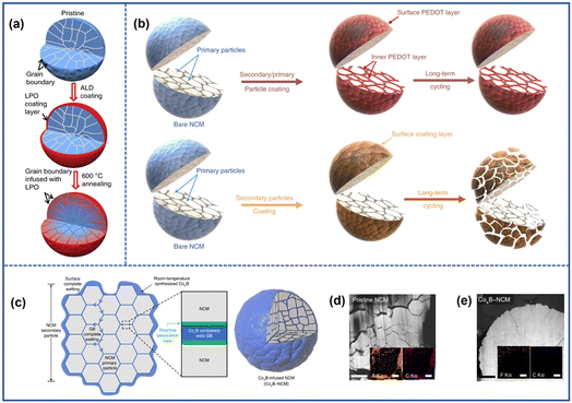 | ||
| Fig. 12 (a) Schematic illustration of the synthesis process of LPO-coated cathodes.90 Reproduced with permission. Copyright © 2018, Springer Nature. (b) Schematic illustration of the synthesis process of the PEDOT-coated cathode.94 Reproduced with permission. Copyright © 2019, Springer Nature. (c) Schematic illustration of the CoxB-coated cathode.95 (d) TEM image and EDS mapping (inset) of pristine NCM (d) and CoxB-NCM (e) after 200 cycles.95 Reproduced with permission. Copyright © 2021, Springer Nature. | ||
However, the procedure of high-temperature treatment may increase the cost and complexity of the synthesis process. To address this issue, Yoon et al.95 proposed a “coating plus-infusion” strategy that can be conducted at room temperature (Fig. 12c). In this approach, the driving force of interfacial chemical reaction drove the CoxB metallic glass to cover both the primary and secondary particles of the LiNi0.80Mn0.10Co0.10O2 cathode material. The CoxB coating layer played a double role by not only acting as a barrier to isolate the particle from the electrolyte but also a stabilizer whose strong bond with the interfacial oxygen helps to suppress the surface oxygen evolution to mitigate the microcrack formation (Fig. 12d and e).
In addition to the control of cathode materials themselves, electrolytes can also contribute to the stability of NRO particles in view of the inevitable interface reaction between the electrolyte and electrode materials. Therefore, it becomes a logical choice to develop a stable NRO particle surface by means of electrolyte engineering. As discussed before, the parasitic interface reaction would accelerate the generation of cracks which in turn exacerbates the chemo-mechanical failure, thereby leading to continuous degradation of battery performance. In this regard, a proper design of electrolytes that ensures a stable electrode–electrolyte interface can be efficient to circumvent the structural degradation of cathode materials with minimized interface side reactions. Accordingly, different functional additives of electrolyte are in high demand for the construction of a stable cathode-electrolyte interface.96–99 For example, Cheng et al.100 found that the addition of lithium difluoro(oxalato)borate and tris(trimethylsilyl)phosphate into the carbonate electrolyte contributed enormously to the microcrack suppression. During cycling, these two additives would undergo oxidization and decomposition to form stable F, B, and Si-rich cathode-electrolyte interface (CEI) layers, whose existence could act as effective protective layers to diminish the continuous decomposition of the electrolyte and the dissolution of transition metal ions. As a result, the cathode cycled with the modified electrolyte remained stable without noticeable microcracks after 400 cycles.
In summary, the surface modification strategy effectively alleviates the detrimental effect of microcracks by using the different characteristics of various coating materials to modify the electrode–electrolyte interface. A desirable coating layer is uniform and has an appropriate thickness, which can provide sufficient protection to the cathode surface. It should also possess the functions like facilitating charge transfer and reducing the surface resistance of the cathode material. Additionally, the coating materials should be cost-effective. Therefore, it is important to focus on the development and selection of suitable coating materials and to establish methods that allow for precise control of the coating layer, including both its thickness and composition.
4.2 Bulk modification
In addition to the parasitic reactions occurring at the electrode–electrolyte interface, the anisotropic lattice volume change induced by the irreversible H2–H3 phase transition and formation of the rock-salt phase caused by the severe Li/Ni mixing within the bulk phase of NROs can also contribute to the formation of microcracks. Thus, modifying the bulk phase of NROs by controlling the composition or microstructure is crucial for effectively inhibiting crack generation. This can be achieved through methods such as element doping or the construction of a concentration gradient structure.The introduction of different cations into the crystalline framework would exhibit location preference according to their elemental nature. For example, cations with high valence like Al3+, Ti4+, Zr4+, and Nb5+ tend to occupy the sites of transition metal layers while low-valence cations like Na+ can occupy the Li site.101–105 The cation doping could contribute to the stability of NROs mainly in the following three aspects:
(1) enhancing the reversibility of the H2–H3 phase transition by introducing a stronger M–O bond. Cations such as Nb5+, Sn4+, Zr4+, Ga3+, and Fe3+ can form stronger M–O bonds compared to Ni3+ due to their higher bonding energy with O2−.106–108 The strong M–O bond is beneficial to maintain the bond angle between transition metal layers, which improves the reversibility of the H2–H3 phase transition and provides better structural stability. Jamil et al.108 demonstrated that after introducing Ga3+ into the bulk structure of the LiNi0.94Co0.045Mn0.015O2 cathode, the location and intensity of the H2–H3 peak hardly changed after cycling compared to the unmodified samples, as shown in Fig. 13a. As a result, the formation of microcracks within the cathode particles was suppressed, leading to a high-capacity retention of 90.1% after 100 cycles at 0.5C, compared to the pristine samples of 68.5%.
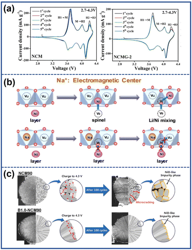 | ||
| Fig. 13 (a) Cyclic voltammetry curves of pristine and Ga-doped NCM (NCMG-2).108 Reproduced with permission. Copyright © 2022, Elsevier. (b) Schematic illustration of the function mechanism of Na to suppress the Li/Ni mixing.110 Reproduced with permission. Copyright © 2018, Elsevier. (c) Schematic illustration of the effect of boron doping.111 Reproduced with permission. Copyright © 2018, WILEY-VCH. | ||
(2) Suppressing Li+/Ni2+ mixing by increasing the energy barriers for Ni2+ migration. Generally, the migration pathway of Ni2+ to the Li layers involves initially moving from the octahedral site of the TM layers to the adjacent tetrahedral site and subsequently occupying the octahedral site of the Li layers.109 Shen et al.110 discovered that the Na+ in the Li layers, due to their higher number of extranuclear electrons compared to Li+, could act as electromagnetic centers, generating stronger electromagnetic force. The enhanced electromagnetic force increased the energy barriers for the migration of Ni2+ to the tetrahedral vacancies, effectively suppressing the undesirable Li/Ni mixing process as illustrated in Fig. 13b.
(3) Accelerating the diffusion of Li+ by increasing the Li layer spacing. In the study of Li et al.,112 the effect of the Nb5+ dopant on the diffusion of Li+ was investigated. It is observed that the presence of the Nb5+ dopant led to an increase in the heights of interlayer spaces within cathode materials due to their stronger repulsion with the transition metal (TM) ions. The larger interlayer spaces would provide an enhanced pathway for Li+ migration, resulting in improved Li+ diffusion kinetics and enhanced rate capacity of the material.
(4) Eliminating the localized stress concentration by tailoring the microstructure of the cathodes. The introduction of elements such as Ta, Nb, and W into the lattice can reduce the surface energy of the (003) plane, thus promoting the growth of primary particles along the radial direction with the shape enclosed on the sides by the (003) plane.111,113,114 Park et al.111 developed B-doped Li(Ni0.90Co0.05Mn0.05)O2 (B1.0-NCM) with a racial crystallographic texture by incorporating B2O3 during the lithiation process of the precursor. The modified cathodes exhibited thin and elongated primary particles aligned along the radial direction, as illustrated in Fig. 13c. This unique structure provided a uniform strain distribution, effectively eliminating microcracks and improving cycling stability. As a result, the B1.0-NCM cathodes were able to attain a capacity retention of 91% after 100 cycles at 55 °C.
Encouraged by the benefits of element doping, systematic doping design by integrating multiple doping elements is therefore enabled in the pursuit of stable NRC cathodes. Ou et al.115 proposed a LiNi0.88Co0.09Mn0.03O2 cathode with Al/Zr co-doping (AZ0.3-SNCM), where Al3+ dispersed across the bulk structure and Zr4+ tended to enrich on the surface. The Al3+ and Zr4+co-doping inhibited the Li/Ni cation mixing and resisted the contraction of lattice contraction in the highly delithiated state, thereby promoting faster Li+ transport and alleviating the interior strain (Fig. 14a). Meanwhile, the accumulation of Zr on the surface of cathodes also helped to suppress the side effect between the electrode and electrolyte. As a result, the modified cathode material (AZ0.3-SNCM) succeeded in diminishing the formation of cracks and maintaining its layer structure after 150 cycles in the 2.75–4.6 V range, showing a stark contrast to the clear collapse of the crystalline structure observed in the pristine cathodes (Fig. 14b–e). Interestingly, Zhang et al.116 proposed a high entropy doping strategy to prepare LiNi0.8Mn0.13Ti0.02Mg0.02Nb0.01Mo0.02O2 (HE-LNMO) cathodes. The as-prepared cathodes were able to reduce the volumetric strain to 0.3% (Fig. 14f) compared to the pristine cathode of 2.7%, which alleviated the mechanical cracking and lattice defect. In addition, due to the pinning effect of multiple dopants, oxygen release and harmful phase transition were also suppressed. The thermal stability of cathodes was also improved, which was comparable with NCM523 with a lower Ni content (Fig. 14g). Benefiting from the special design, the cathodes accomplished an excellent capacity retention of 85% after 1000 cycles.
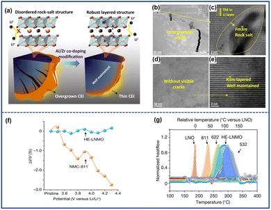 | ||
| Fig. 14 (a) Schematic illustration comparing the difference in crack evolution and internal structures between pristine (SCNM) and modified cathodes (AZ0.3-SNCM).115 Cross-sectional TEM (b) and corresponding STEM image (c) of cycled SNCM.115 Cross-sectional TEM (d) and corresponding STEM image (e) of cycled AZ0.3-SNCM.115 Reproduced with permission. Copyright © 2022, Springer Nature. (f) Lattice volume variation of HE-LNMO compared to NMC-811 during initial charging.116 (g) DSC profile of delithiated LiNiO2 (LNO), NMC-811, NMC-622, HE-LNMO and NMC-532.116 Reproduced with permission. Copyright © 2022, Springer Nature. | ||
Apart from the cation ions, anion doping can also be effective in inhibiting cracks and thus improving cycling stability. Unlike cation doping, anions such as F− ions would occupy sites of O2− ions instead of the transition metal ions. The anions with stronger electronegativity would strengthen the chemical bonding between the anions and transition metal ions, therefore enhancing the structural ability. Wang et al.118 found that after the incorporation of F−, the generation of microcracks was inhibited in LiNi0.8Co0.15Al0.05O1.96F0.04. This was attributed to the stronger attraction exhibited by F− to the metal ions compared with O2−, which suppressed the detrimental H2–H3 phase transition and relieved uneven strain distribution within the NRO particles. Additionally, the introduction of low-valence anions such as F− into the bulk phase would increase the number of Ni2+ ions in the bulk to balance the electron neutrality. This may induce the appearance of a special superlattice structure, as proposed by Kim et al.117 They fabricated F-doped Li(Ni0.80Co0.05 Mn0.15)O2 (F1-GC80) cathode materials and found that the Ni2+ orderly migrated to the Li layer during cycling. As shown in Fig. 15a, the Ni2+ migration occurred every two rows in the Li layers, forming a superlattice structure. Such a structure could provide pathways for Li+ to jump into the adjacent TM layers and facilitated their diffusion. Furthermore, the ordered structure also stabilized the lattice in the deeply delithiated state, preventing the slab collapse and reducing the strain within the bulk. Consequently, F1-GC80 after 5000 cycles exhibited fewer microcracks than pristine cathodes after 2000 cycles (GC80) (Fig. 13f).
 | ||
| Fig. 15 (a) Schematic illustration of the structural stability of the charged GC80 and F1-GC80 cathodes with the corresponding high-resolution TEM images.117 (b) TEM and STXM mapping for F1-GC80 (5000 cycles) and GC80 (2000 cycles) cathodes.117 Reproduced with permission. Copyright © 2021, The Royal Society of Chemistry. | ||
In conclusion, employing the method of element doping can efficiently address the issue of microcracks. The heteroatom within the materials would strengthen the structural stability of NROs and improve the electrochemical performance by forming a stronger chemical bond with the host ions or tailoring the microstructure. However, an excess proportion of doping ions may reduce the reversible capacity. Therefore, doping content should be designed precisely to enhance the bulk structure without sacrificing the capacity.
A classic configuration of cathodes with a concertation gradient structure is the full concentration gradient (FCG) proposed by Sun et al.121 In this configuration, as shown in Fig. 16a, from the center of particles to the outer surface, the Ni content gradually decreased, while the relative proportion of Co and Mn increased. The unique design of this configuration could provide sufficient protection to the cathodes when the cell was cycled under a high voltage or an elevated temperature. Moreover, the change in the composition within the bulk can also influence the microstructure. In the cathode with a full concentration gradient structure, the primary particles inside the materials were aligned along the radial direction of the secondary particles. This alignment not only provided fast diffusion channels for Li+ but also regulated the internal stress distribution. Attributed to these benefits, no discernible microcracks were observed in the cathodes with a FCG structure fabricated by Lee et al. even after 2500 cycles, as depicted in Fig. 16b and c.122 To maximize the capacity and enhance the structural stability of NROs with a FCG structure, the conception of two-sloped full concentration gradients (TSFCGs) was proposed.123–125 Lim et al.125 introduced Li(Ni0.84Co0.06Mn0.09Al0.01)O2 (TSFCG-Al) with a TSFCG structure as shown in Fig. 16d. Compared to the pristine Li(Ni0.85Co0.11Al0.04)O2 (NCA) cathode with the same Ni content, the as-fabricated cathodes exhibited not only higher specific capacity but also better cyclability due to the absence of microcracks (Fig. 16g and h). In addition to the commonly studied concentration gradient configurations, novel concentration gradient structures for NROs were proposed recently. These include cathodes with a changeable content of Co and Mn concentration gradients, as well as cathodes with a Ni valence gradient.126,127 These alternative concentration gradient structures have shown promise in microcrack mitigation and performance improvement of NRO materials.
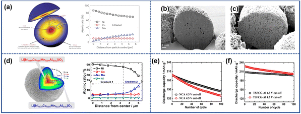 | ||
| Fig. 16 (a) Schematic illustration of particles with the full concentration gradient structure and corresponding EPMA line scan profile.121 Reproduced with permission. Copyright © 2012, Springer Nature. Cross-sectional SEM images of uncycled (b) and cycled (c) FCG cathodes.122 Reproduced with permission. Copyright © 2014, American Chemical Society. (d) Schematic illustration of particles with a two-sloped full concentration gradient structure and corresponding EPMA line scan profile.125 (e) and (f) Cycling performance of TSFCG-Al and NCA at different cut-off voltages.125 Reproduced with permission. Copyright © 2016, American Chemical Society. | ||
The concentration gradient structure strategy offers improved structural stability of cathodes and mitigates the formation of cracks. However, the synthesis of such materials currently relies on the adjustment of the co-precipitation step, which requires extra reactors, thus increasing the cost although there are reports about the one-step method.128 Furthermore, achieving the optimal electrochemical performance for cathodes with different Ni contents requires precise temperature control, which is challenging due to the unique concentration gradient. Additionally, the limited Ni content in the structure may sacrifice the electrochemical capacity of cathodes.
5. Conclusions
Ni-rich layered metal oxides (NROs) hold great promise as cathode materials for lithium-ion batteries (LIBs) due to their high capacity and low cost. However, they face challenges related to chemical and structural instability, leading to chemo-mechanical failure and limiting their practical application. Notably, the emergence of microcracks within NRO particles caused by an uneven stress field is considered a significant characteristic for such failures, as their evolution worsens the performance degradation. Therefore, gaining an in-depth understanding of this issue is crucial for the further development of NROs. This review provides a comprehensive discussion of the formation mechanism of microcracks and their impact on electrode performance. It also summarizes various strategies to address these challenges and mitigate the detrimental effects of microcracks in NROs.These microcracks within the particles can be categorized into intragranular cracks appearing inside the primary particles and intergranular cracks growing along the grain boundaries. The generation mechanisms for these two types of cracks are different. For the former one, their formation is closely related to inhomogeneous Li+ distribution and structural defects within the materials. The latter is attributed to three aspects: the anisotropic change of the lattice parameter, the detrimental H2–H3 phase transition, and the working conditions.
Once microcracks are formed within NROs, they serve as channels to expedite the penetration of electrolyte and induce adverse side reactions, resulting in the detrimental phase transition and dissolution of transition metal ions. Furthermore, the formation of microcracks can cause the separation of particles, hindering the migration of Li+ and electrons. This separation becomes more severe over time, eventually isolating certain particles from the rest of the electrode and contributing to the capacity loss. Moreover, microcracks can propagate between adjacent particles. The more severely damaged particles induce damage to neighboring particles under the effect of the simultaneous driving force to eliminate the heterogeneity, which further compromises the overall structural integrity.
Various strategies can be employed to inhibit the formation and propagation of microcracks in NRO materials. These methods can be categorized into surface and bulk modification, targeting the physicochemical properties of the surface and bulk phase, respectively. Surface modification focuses on improving the stability of the electrode–electrolyte interface by modifying either the surface of the NRO particles or the grain boundaries. Bulk modification strategies involve tuning the composition or structure of the bulk of the NRO materials, which can be achieved through methods such as element doping or creating concentration gradients within the cathode.
Despite significant advancements in controlling microcracks in NRO materials, it is important to acknowledge that further improvements are still needed. Here are some potential research directions and opportunities that can aid in the design of crack-free cathodes.
(1) Advanced characterization for further mechanism study. Currently, the existence of microcracks is typically analyzed by techniques such as TEM and SEM after the batteries have been stopped and disassembled. While these methods provide valuable information about the microcrack propagation, our understanding of the evolution of cracks is still limited, particularly when considering their atomic-level behavior during the cycling. Therefore, there is a need for further investigation to study the formation and failure mechanism of microcracks at the atomic scale by real-time observation. Such research can provide valuable insights into the underlying evolutionary mechanisms of microcracks, which would aid in predicting and optimizing cathode structure for the development of more robust and reliable cathode materials.
(2) Combination of different types of modification methods. While individual methods discussed in this review have shown improvements, their benefit is limited when applied alone, and is hard to meet the stricter stability requirements in the future. By combining multiple strategies, it becomes possible to leverage the benefits of each method, further enhancing the electrochemical performance of batteries. One promising approach is the simultaneous adoption of surface coating and bulk element doping. The coating layers would inhibit the direct contact between the electrode and electrolyte while the heteroatom within the lattice may alleviate the internal strain during the cycling thereby enhancing surface and bulk stability. This comprehensive approach holds great potential for mitigating the occurrence of microcracks and minimizing their detrimental effects on battery performance.
(3) Control strategies suited for scalable production. Apart from focusing on the benefits of modification strategies of NROs, their scalability for commercial production needs to be considered. For example, techniques like atomic layer deposition offer precise control of coating layers, but their high cost and complex process can limit their practicality in large-scale manufacturing. To successfully integrate these modifications into commercial production, it is essential to develop strategies that are not only effective but also compatible with industrial-scale manufacturing processes. This includes carefully selecting raw materials with reasonable costs and ensuring their compatibility with existing production equipment. By addressing these aspects, the modification techniques can be efficiently implemented in large-scale manufacturing, promoting the further application of NROs.
Author contributions
The manuscript was written with the contributions of all authors. All authors have approved the final version of the manuscript.Conflicts of interest
There are no conflicts to declare.Acknowledgements
This work was supported by the National Key R&D Program of China (Grant No. 2022YFB2404402), the National Natural Science Foundation of China (Grant No. 22025507 and 21931012), the Key Research Program of Frontier Sciences, CAS (ZDBS-LYSLH020), and the Beijing National Laboratory for Molecular Sciences (BNLMS-CXXM-202010).Notes and references
- M. Chen, X. Ma, B. Chen, R. Arsenault, P. Karlson, N. Simon and Y. Wang, Joule, 2019, 3, 2622–2646 CrossRef CAS.
- J. B. Goodenough and K.-S. Park, J. Am. Chem. Soc., 2013, 135, 1167–1176 CrossRef CAS PubMed.
- J. W. Choi and D. Aurbach, Nat. Rev. Mater., 2016, 1, 16013 CrossRef CAS.
- T.-H. Kim, J.-S. Park, S. K. Chang, S. Choi, J. H. Ryu and H.-K. Song, Adv. Energy Mater., 2012, 2, 860–872 CrossRef CAS.
- B. Xu, D. Qian, Z. Wang and Y. S. Meng, Mater. Sci. Eng., R, 2012, 73, 51–65 CrossRef CAS.
- H. Maleki Kheimeh Sari and X. Li, Adv. Energy Mater., 2019, 9, 1901597 CrossRef CAS.
- M. Li, J. Lu, Z. Chen and K. Amine, Adv. Mater., 2018, 30, 1800561 CrossRef PubMed.
- W. Liu, P. Oh, X. Liu, M.-J. Lee, W. Cho, S. Chae, Y. Kim and J. Cho, Angew. Chem., Int. Ed., 2015, 54, 4440–4457 CrossRef CAS PubMed.
- S.-D. Zhang, M.-Y. Qi, S.-J. Guo, Y.-G. Sun, X.-X. Tan, P.-Z. Ma, J.-Y. Li, R.-Z. Yuan, A.-M. Cao and L.-J. Wan, Small Methods, 2022, 6, 2200148 CrossRef CAS PubMed.
- Y.-h. Luo, H.-X. Wei, L.-b. Tang, Y.-d. Huang, Z.-Y. Wang, Z.-j. He, C. Yan, J. Mao, K. Dai and J.-c. Zheng, Energy Storage Mater., 2022, 50, 274–307 CrossRef.
- H.-H. Ryu, H. H. Sun, S.-T. Myung, C. S. Yoon and Y.-K. Sun, Energy Environ. Sci., 2021, 14, 844–852 RSC.
- N. Voronina, Y.-K. Sun and S.-T. Myung, ACS Energy Lett., 2020, 5, 1814–1824 CrossRef CAS.
- H.-H. Ryu, K.-J. Park, C. S. Yoon and Y.-K. Sun, Chem. Mater., 2018, 30, 1155–1163 CrossRef CAS.
- X. Wang, Y. L. Ding, Y. P. Deng and Z. Chen, Adv. Energy Mater., 2020, 10, 1903864 CrossRef CAS.
- L. Liang, W. Zhang, F. Zhao, D. K. Denis, F. U. Zaman, L. Hou and C. Yuan, Adv. Mater. Interfaces, 2020, 7, 1901749 CrossRef CAS.
- L. Qiu, Y. Song, M. Zhang, Y. Liu, Z. Yang, Z. Wu, H. Zhang, W. Xiang, Y. Liu, G. Wang, Y. Sun, J. Zhang, B. Zhang and X. Guo, Adv. Energy Mater., 2022, 12, 2200022 CrossRef CAS.
- S.-T. Myung, F. Maglia, K.-J. Park, C. S. Yoon, P. Lamp, S.-J. Kim and Y.-K. Sun, ACS Energy Lett., 2017, 2, 196–223 CrossRef CAS.
- H. Zhang, F. Omenya, P. Yan, L. Luo, M. S. Whittingham, C. Wang and G. Zhou, ACS Energy Lett., 2017, 2, 2607–2615 CrossRef CAS.
- X. Xu, H. Huo, J. Jian, L. Wang, H. Zhu, S. Xu, X. He, G. Yin, C. Du and X. Sun, Adv. Energy Mater., 2019, 9, 1803963 CrossRef.
- H. Liu, M. Wolfman, K. Karki, Y.-S. Yu, E. A. Stach, J. Cabana, K. W. Chapman and P. J. Chupas, Nano Lett., 2017, 17, 3452–3457 CrossRef CAS PubMed.
- W. E. Gent, Y. Li, S. Ahn, J. Lim, Y. Liu, A. M. Wise, C. B. Gopal, D. N. Mueller, R. Davis, J. N. Weker, J.-H. Park, S.-K. Doo and W. C. Chueh, Adv. Mater., 2016, 28, 6631–6638 CrossRef CAS PubMed.
- H.-H. Ryu, G.-T. Park, C. S. Yoon and Y.-K. Sun, Small, 2018, 14, 1803179 CrossRef PubMed.
- R. Jung, F. Linsenmann, R. Thomas, J. Wandt, S. Solchenbach, F. Maglia, C. Stinner, M. Tromp and H. A. Gasteiger, J. Electrochem. Soc., 2019, 166, A378–A389 CrossRef CAS.
- H.-R. Kim, S.-G. Woo, J.-H. Kim, W. Cho and Y.-J. Kim, J. Electroanal. Chem., 2016, 782, 168–173 CrossRef CAS.
- L. Qiu, M. Zhang, Y. Song, Z. Wu, H. Zhang, W. Hua, Y. Sun, Q. Kong, W. Feng, K. Wang, Y. Xiao and X. Guo, Angew. Chem., Int. Ed., 2023, 62, e202300209 CrossRef CAS PubMed.
- P. Yan, J. Zheng, M. Gu, J. Xiao, J.-G. Zhang and C.-M. Wang, Nat. Commun., 2017, 8, 14101 CrossRef CAS PubMed.
- J. Langdon and A. Manthiram, Energy Storage Mater., 2021, 37, 143–160 CrossRef.
- H. Zhang, X. He, Z. Chen, Y. Yang, H. Xu, L. Wang and X. He, Adv. Energy Mater., 2022, 12, 2202022 CrossRef CAS.
- H.-H. Ryu, B. Namkoong, J.-H. Kim, I. Belharouak, C. S. Yoon and Y.-K. Sun, ACS Energy Lett., 2021, 6, 2726–2734 CrossRef CAS.
- F. Zhang, S. Lou, S. Li, Z. Yu, Q. Liu, A. Dai, C. Cao, M. F. Toney, M. Ge, X. Xiao, W.-K. Lee, Y. Yao, J. Deng, T. Liu, Y. Tang, G. Yin, J. Lu, D. Su and J. Wang, Nat. Commun., 2020, 11, 3050 CrossRef CAS PubMed.
- L. Ni, S. Zhang, A. Di, W. Deng, G. Zou, H. Hou and X. Ji, Adv. Energy Mater., 2022, 12, 2201510 CrossRef CAS.
- Y. Xia, J. Zheng, C. Wang and M. Gu, Nano Energy, 2018, 49, 434–452 CrossRef CAS.
- Q. Lin, W. Guan, J. Zhou, J. Meng, W. Huang, T. Chen, Q. Gao, X. Wei, Y. Zeng, J. Li and Z. Zhang, Nano Energy, 2020, 76, 105021 CrossRef CAS.
- L. Mu, R. Lin, R. Xu, L. Han, S. Xia, D. Sokaras, J. D. Steiner, T.-C. Weng, D. Nordlund, M. M. Doeff, Y. Liu, K. Zhao, H. L. Xin and F. Lin, Nano Lett., 2018, 18, 3241–3249 CrossRef CAS PubMed.
- P. Yan, J. Zheng, T. Chen, L. Luo, Y. Jiang, K. Wang, M. Sui, J.-G. Zhang, S. Zhang and C. Wang, Nat. Commun., 2018, 9, 2437 CrossRef PubMed.
- B. You, Z. Wang, F. Shen, Y. Chang, W. Peng, X. Li, H. Guo, Q. Hu, C. Deng, S. Yang, G. Yan and J. Wang, Small Methods, 2021, 5, 2100234 CrossRef CAS PubMed.
- Y. Su, Q. Zhang, L. Chen, L. Bao, Y. Lu, Q. Shi, J. Wang, S. Chen and F. Wu, ACS Appl. Mater. Interfaces, 2020, 12, 37208–37217 CrossRef CAS PubMed.
- A. O. Kondrakov, H. Geßwein, K. Galdina, L. de Biasi, V. Meded, E. O. Filatova, G. Schumacher, W. Wenzel, P. Hartmann, T. Brezesinski and J. Janek, J. Phys. Chem. C, 2017, 121, 24381–24388 CrossRef CAS.
- Y. Makimura, S. Zheng, Y. Ikuhara and Y. Ukyo, J. Electrochem. Soc., 2012, 159, A1070 CrossRef CAS.
- J.-M. Lim, T. Hwang, D. Kim, M.-S. Park, K. Cho and M. Cho, Sci. Rep., 2017, 7, 39669 CrossRef CAS PubMed.
- H.-H. Sun and A. Manthiram, Chem. Mater., 2017, 29, 8486–8493 CrossRef CAS.
- A. O. Kondrakov, A. Schmidt, J. Xu, H. Geßwein, R. Mönig, P. Hartmann, H. Sommer, T. Brezesinski and J. Janek, J. Phys. Chem. C, 2017, 121, 3286–3294 CrossRef CAS.
- D.-H. Seo, A. Urban and G. Ceder, Phys. Rev. B: Condens. Matter Mater. Phys., 2015, 92, 115118 CrossRef.
- W. Li, J. N. Reimers and J. R. Dahn, Solid State Ionics, 1993, 67, 123–130 CrossRef CAS.
- W. Li, H. Y. Asl, Q. Xie and A. Manthiram, J. Am. Chem. Soc., 2019, 141, 5097–5101 CrossRef CAS PubMed.
- J.-H. Kim, H.-H. Ryu, S. J. Kim, C. S. Yoon and Y.-K. Sun, ACS Appl. Mater. Interfaces, 2019, 11, 30936–30942 CrossRef CAS PubMed.
- C. S. Yoon, D.-W. Jun, S.-T. Myung and Y.-K. Sun, ACS Energy Lett., 2017, 2, 1150–1155 CrossRef CAS.
- C. S. Yoon, H.-H. Ryu, G.-T. Park, J.-H. Kim, K.-H. Kim and Y.-K. Sun, J. Mater. Chem. A, 2018, 6, 4126–4132 RSC.
- C. Xu, P. J. Reeves, Q. Jacquet and C. P. Grey, Adv. Energy Mater., 2020, 11, 2003404 CrossRef.
- G. W. Nam, N.-Y. Park, K.-J. Park, J. Yang, J. Liu, C. S. Yoon and Y.-K. Sun, ACS Energy Lett., 2019, 4, 2995–3001 CrossRef CAS.
- S. Watanabe, M. Kinoshita, T. Hosokawa, K. Morigaki and K. Nakura, J. Power Sources, 2014, 258, 210–217 CrossRef CAS.
- K.-J. Park, J.-Y. Hwang, H.-H. Ryu, F. Maglia, S.-J. Kim, P. Lamp, C. S. Yoon and Y.-K. Sun, ACS Energy Lett., 2019, 4, 1394–1400 CrossRef CAS.
- S. Yin, W. Deng, J. Chen, X. Gao, G. Zou, H. Hou and X. Ji, Nano Energy, 2021, 83, 105854 CrossRef CAS.
- W. Wei, Z. Ding, C. Chen, C. Yang, B. Han, L. Xiao, C. Liang, P. Gao and K. Cho, Acta Mater., 2021, 212, 116914 CrossRef CAS.
- N.-Y. Park, G.-T. Park, S.-B. Kim, W. Jung, B.-C. Park and Y.-K. Sun, ACS Energy Lett., 2022, 7, 2362–2369 CrossRef CAS.
- M. Jiang, D. L. Danilov, R. A. Eichel and P. H. L. Notten, Adv. Energy Mater., 2021, 11, 2103005 CrossRef CAS.
- B. Xiao and X. Sun, Adv. Energy Mater., 2018, 8, 1802057 CrossRef.
- D.-S. Ko, J.-H. Park, S. Park, Y. N. Ham, S. J. Ahn, J.-H. Park, H. N. Han, E. Lee, W. S. Jeon and C. Jung, Nano Energy, 2019, 56, 434–442 CrossRef CAS.
- J. Kim, H. Ma, H. Cha, H. Lee, J. Sung, M. Seo, P. Oh, M. Park and J. Cho, Energy Environ. Sci., 2018, 11, 1449–1459 RSC.
- S. Xia, L. Mu, Z. Xu, J. Wang, C. Wei, L. Liu, P. Pianetta, K. Zhao, X. Yu, F. Lin and Y. Liu, Nano Energy, 2018, 53, 753–762 CrossRef CAS.
- M. M. Besli, S. Xia, S. Kuppan, Y. Huang, M. Metzger, A. K. Shukla, G. Schneider, S. Hellstrom, J. Christensen, M. M. Doeff and Y. Liu, Chem. Mater., 2019, 31, 491–501 CrossRef CAS.
- S. Y. Park, W. J. Baek, S. Y. Lee, J. A. Seo, Y.-S. Kang, M. Koh and S. H. Kim, Nano Energy, 2018, 49, 1–6 CrossRef CAS.
- D. J. Miller, C. Proff, J. G. Wen, D. P. Abraham and J. Bareño, Adv. Energy Mater., 2013, 3, 1098–1103 CrossRef CAS.
- C. Tian, Y. Xu, D. Nordlund, F. Lin, J. Liu, Z. Sun, Y. Liu and M. Doeff, Joule, 2018, 2, 464–477 CrossRef CAS.
- F. Lin, K. Zhao and Y. Liu, ACS Energy Lett., 2021, 6, 4065–4070 CrossRef CAS.
- D. A. Santos, S. Rezaei, D. Zhang, Y. Luo, B. Lin, A. R. Balakrishna, B.-X. Xu and S. Banerjee, Chem. Sci., 2023, 14, 458–484 RSC.
- J. Xiao, Science, 2022, 376, 455–456 CrossRef CAS PubMed.
- J. Li, N. Sharma, Z. Jiang, Y. Yang, F. Monaco, Z. Xu, D. Hou, D. Ratner, P. Pianetta, P. Cloetens, F. Lin, K. Zhao and Y. Liu, Science, 2022, 376, 517–521 CrossRef CAS PubMed.
- X. Fan, X. Ou, W. Zhao, Y. Liu, B. Zhang, J. Zhang, L. Zou, L. Seidl, Y. Li, G. Hu, C. Battaglia and Y. Yang, Nat. Commun., 2021, 12, 5320 CrossRef CAS PubMed.
- H. Yang, R.-M. Gao, X.-D. Zhang, J.-Y. Liang, X.-H. Meng, Z.-Y. Lu, F.-F. Cao and H. Ye, Adv. Mater., 2022, 34, 2204835 CrossRef CAS PubMed.
- S. Chen, T. He, Y. Su, Y. Lu, L. Bao, L. Chen, Q. Zhang, J. Wang, R. Chen and F. Wu, ACS Appl. Mater. Interfaces, 2017, 9, 29732–29743 CrossRef CAS PubMed.
- H. Yu, Y. Cao, L. Chen, Y. Hu, X. Duan, S. Dai, C. Li and H. Jiang, Nat. Commun., 2021, 12, 4564 CrossRef CAS PubMed.
- J. Wang, S.-D. Zhang, S.-J. Guo, S.-Q. Lu, Y.-S. Xu, J.-Y. Li, A.-M. Cao and L.-J. Wan, Nano Res., 2023, 16, 2480–2485 CrossRef CAS.
- Y. L. Sidong Zhang, M. Qi and A. Cao, Acta Phys.-Chim. Sin., 2021, 37, 2011007 Search PubMed.
- L. Wang, L. Xie, Y. Song, X. Liu, H. Zhang and X. He, Battery Energy, 2023, 2, 20220025 CrossRef CAS.
- L. Yao, F. Liang, J. Jin, B. V. R. Chowdari, J. Yang and Z. Wen, Chem. Eng. J., 2020, 389, 124403 CrossRef CAS.
- X. Meng, H. Cao, J. Hao, P. Ning, G. Xu and Z. Sun, ACS Sustain. Chem. Eng., 2018, 6, 5797–5805 CrossRef CAS.
- D. Hu, Y. Su, L. Chen, N. Li, L. Bao, Y. Lu, Q. Zhang, J. Wang, S. Chen and F. Wu, J. Energy Chem., 2021, 58, 1–8 CrossRef CAS.
- D. Becker, M. Börner, R. Nölle, M. Diehl, S. Klein, U. Rodehorst, R. Schmuch, M. Winter and T. Placke, ACS Appl. Mater. Interfaces, 2019, 11, 18404–18414 CrossRef CAS PubMed.
- R. S. Negi, S. P. Culver, A. Mazilkin, T. Brezesinski and M. T. Elm, ACS Appl. Mater. Interfaces, 2020, 12, 31392–31400 CrossRef CAS PubMed.
- Z. Ahaliabadeh, X. Kong, E. Fedorovskaya and T. Kallio, J. Power Sources, 2022, 540, 231633 CrossRef CAS.
- S.-Q. Lu, Q. Zhang, F. Meng, Y.-N. Liu, J. Mao, S. Guo, M.-Y. Qi, Y.-S. Xu, Y. Qiao, S.-D. Zhang, K. Jiang, L. Gu, Y. Xia, S. Chen, G. Chen, A.-M. Cao and L.-J. Wan, J. Am. Chem. Soc., 2023, 145, 7397–7407 CrossRef CAS PubMed.
- J. Xie, A. D. Sendek, E. D. Cubuk, X. Zhang, Z. Lu, Y. Gong, T. Wu, F. Shi, W. Liu, E. J. Reed and Y. Cui, ACS Nano, 2017, 11, 7019–7027 CrossRef CAS PubMed.
- C. Xu, W. Xiang, Z. Wu, Y. Xu, Y. Li, Y. Wang, Y. Xiao, X. Guo and B. Zhong, ACS Appl. Mater. Interfaces, 2019, 11, 16629–16638 CrossRef CAS PubMed.
- Y. Chu, Y. Mu, L. Zou, Y. Hu, J. Cheng, B. Wu, M. Han, S. Xi, Q. Zhang and L. Zeng, Adv. Mater., 2023, 35, 2212308 CrossRef CAS PubMed.
- L. Wang, G. Liu, R. Wang, X. Wang, L. Wang, Z. Yao, C. Zhan and J. Lu, Adv. Mater., 2023, 35, 2209483 CrossRef CAS PubMed.
- X. Liu, X. Zhou, Q. Liu, J. Diao, C. Zhao, L. Li, Y. Liu, W. Xu, A. Daali, R. Harder, I. K. Robinson, M. Dahbi, J. Alami, G. Chen, G.-L. Xu and K. Amine, Adv. Mater., 2022, 34, 2107326 CrossRef CAS PubMed.
- Q. Gan, N. Qin, Y. Zhu, Z. Huang, F. Zhang, S. Gu, J. Xie, K. Zhang, L. Lu and Z. Lu, ACS Appl. Mater. Interfaces, 2019, 11, 12594–12604 CrossRef CAS PubMed.
- U. Nisar, N. Muralidharan, R. Essehli, R. Amin and I. Belharouak, Energy Storage Mater., 2021, 38, 309–328 CrossRef.
- P. Yan, J. Zheng, J. Liu, B. Wang, X. Cheng, Y. Zhang, X. Sun, C. Wang and J.-G. Zhang, Nat. Energy, 2018, 3, 600–605 CrossRef CAS.
- H. Kim, M. G. Kim, H. Y. Jeong, H. Nam and J. Cho, Nano Lett., 2015, 15, 2111–2119 CrossRef CAS PubMed.
- H. Kim, S. Lee, H. Cho, J. Kim, J. Lee, S. Park, S. H. Joo, S. H. Kim, Y. G. Cho, H. K. Song, S. K. Kwak and J. Cho, Adv. Mater., 2016, 28, 4705–4712 CrossRef CAS PubMed.
- F. Du, P. Sun, Q. Zhou, D. Zeng, D. Hu, Z. Fan, Q. Hao, C. Mei, T. Xu and J. Zheng, ACS Appl. Mater. Interfaces, 2020, 12, 56963–56973 CrossRef CAS PubMed.
- G.-L. Xu, Q. Liu, K. K. S. Lau, Y. Liu, X. Liu, H. Gao, X. Zhou, M. Zhuang, Y. Ren, J. Li, M. Shao, M. Ouyang, F. Pan, Z. Chen, K. Amine and G. Chen, Nat. Energy, 2019, 4, 484–494 CrossRef CAS.
- M. Yoon, Y. Dong, J. Hwang, J. Sung, H. Cha, K. Ahn, Y. Huang, S. J. Kang, J. Li and J. Cho, Nat. Energy, 2021, 6, 362–371 CrossRef CAS.
- M. Mao, X. Ji, Q. Wang, Z. Lin, M. Li, T. Liu, C. Wang, Y.-S. Hu, H. Li, X. Huang, L. Chen and L. Suo, Nat. Commun., 2023, 14, 1082 CrossRef CAS PubMed.
- S. Tan, Z. Shadike, J. Li, X. Wang, Y. Yang, R. Lin, A. Cresce, J. Hu, A. Hunt, I. Waluyo, L. Ma, F. Monaco, P. Cloetens, J. Xiao, Y. Liu, X.-Q. Yang, K. Xu and E. Hu, Nat. Energy, 2022, 7, 484–494 CrossRef CAS.
- L. Li, D. Wang, G. Xu, Q. Zhou, J. Ma, J. Zhang, A. Du, Z. Cui, X. Zhou and G. Cui, J. Energy Chem., 2022, 65, 280–292 CrossRef CAS.
- L. Su, K. Jarvis, H. Charalambous, A. Dolocan and A. Manthiram, Adv. Funct. Mater., 2023, 33, 2213675 CrossRef CAS.
- F. Cheng, X. Zhang, P. Wei, S. Sun, Y. Xu, Q. Li, C. Fang, J. Han and Y. Huang, Sci. Bull., 2022, 67, 2225–2234 CrossRef CAS.
- L. Cheng, Y. Zhou, B. Zhang, W. Wang, L. Ming, Z. Xiao and X. Ou, Chem. Eng. J., 2023, 452, 139336 CrossRef CAS.
- Y. Zhang, J. Liu, W. Xu, Y. Lu, H. Ma, F. Cheng and J. Chen, J. Power Sources, 2022, 535, 231445 CrossRef CAS.
- F. Wu, N. Liu, L. Chen, Y. Su, G. Tan, L. Bao, Q. Zhang, Y. Lu, J. Wang, S. Chen and J. Tan, Nano Energy, 2019, 59, 50–57 CrossRef CAS.
- H. Xie, K. Du, G. Hu, Z. Peng and Y. Cao, J. Phys. Chem. C, 2016, 120, 3235–3241 CrossRef CAS.
- F. Xin, H. Zhou, Y. Zong, M. Zuba, Y. Chen, N. A. Chernova, J. Bai, B. Pei, A. Goel, J. Rana, F. Wang, K. An, L. F. J. Piper, G. Zhou and M. S. Whittingham, ACS Energy Lett., 2021, 6, 1377–1382 CrossRef CAS.
- W. Che, X. Wan, D. Zhang and C. Chang, ACS Sustain. Chem. Eng., 2021, 9, 5536–5545 CrossRef CAS.
- M. Eilers-Rethwisch, M. Winter and F. M. Schappacher, J. Power Sources, 2018, 387, 101–107 CrossRef CAS.
- S. Jamil, L. Yue, C. Li, M. Fasehullah, M. Aizaz Ud Din, W. Yang, S. Bao and M. Xu, Chem. Eng. J., 2022, 441, 135821 CrossRef CAS.
- D. Eum, B. Kim, S. J. Kim, H. Park, J. Wu, S.-P. Cho, G. Yoon, M. H. Lee, S.-K. Jung, W. Yang, W. M. Seong, K. Ku, O. Tamwattana, S. K. Park, I. Hwang and K. Kang, Nat. Mater., 2020, 19, 419–427 CrossRef CAS PubMed.
- Y. Shen, X. Yao, J. Zhang, S. Wang, D. Zhang, D. Yin, L. Wang, Y. Zhang, J. Hu, Y. Cheng and X. Li, Nano Energy, 2022, 94, 106900 CrossRef CAS.
- K.-J. Park, H.-G. Jung, L.-Y. Kuo, P. Kaghazchi, C. S. Yoon and Y.-K. Sun, Adv. Energy Mater., 2018, 8, 1801202 CrossRef.
- J. Li, M. Zhang, D. Zhang, Y. Yan and Z. Li, Chem. Eng. J., 2020, 402, 126195 CrossRef CAS.
- H.-H. Ryu, N.-Y. Park, J. H. Seo, Y.-S. Yu, M. Sharma, R. Mücke, P. Kaghazchi, C. S. Yoon and Y.-K. Sun, Mater. Today, 2020, 36, 73–82 CrossRef CAS.
- H.-H. Ryu, N.-Y. Park, D. R. Yoon, U.-H. Kim, C. S. Yoon and Y.-K. Sun, Adv. Energy Mater., 2020, 10, 2000495 CrossRef CAS.
- X. Ou, T. Liu, W. Zhong, X. Fan, X. Guo, X. Huang, L. Cao, J. Hu, B. Zhang, Y. S. Chu, G. Hu, Z. Lin, M. Dahbi, J. Alami, K. Amine, C. Yang and J. Lu, Nat. Commun., 2022, 13, 2319 CrossRef CAS PubMed.
- R. Zhang, C. Wang, P. Zou, R. Lin, L. Ma, L. Yin, T. Li, W. Xu, H. Jia, Q. Li, S. Sainio, K. Kisslinger, S. E. Trask, S. N. Ehrlich, Y. Yang, A. M. Kiss, M. Ge, B. J. Polzin, S. J. Lee, W. Xu, Y. Ren and H. L. Xin, Nature, 2022, 610, 67–73 CrossRef CAS PubMed.
- U.-H. Kim, G.-T. Park, P. Conlin, N. Ashburn, K. Cho, Y.-S. Yu, D. A. Shapiro, F. Maglia, S.-J. Kim, P. Lamp, C. S. Yoon and Y.-K. Sun, Energy Environ. Sci., 2021, 14, 1573–1583 RSC.
- J. Wang, C. Liu, G. Xu, C. Miao, M. Wen, M. Xu, C. Wang and W. Xiao, Chem. Eng. J., 2022, 438, 135537 CrossRef CAS.
- Y. Zhang, H. Li, J. Liu, J. Zhang, F. Cheng and J. Chen, J. Mater. Chem. A, 2019, 7, 20958–20964 RSC.
- U.-H. Kim, H.-H. Ryu, J.-H. Kim, R. Mücke, P. Kaghazchi, C. S. Yoon and Y.-K. Sun, Adv. Energy Mater., 2019, 9, 1803902 CrossRef.
- Y. K. Sun, Z. Chen, H. J. Noh, D. J. Lee, H. G. Jung, Y. Ren, S. Wang, C. S. Yoon, S. T. Myung and K. Amine, Nat. Mater., 2012, 11, 942–947 CrossRef CAS PubMed.
- E.-J. Lee, Z. Chen, H.-J. Noh, S. C. Nam, S. Kang, D. H. Kim, K. Amine and Y.-K. Sun, Nano Lett., 2014, 14, 4873–4880 CrossRef CAS PubMed.
- B.-B. Lim, S.-J. Yoon, K.-J. Park, C. S. Yoon, S.-J. Kim, J. J. Lee and Y.-K. Sun, Adv. Funct. Mater., 2015, 25, 4673–4680 CrossRef CAS.
- J. H. Lee, C. S. Yoon, J.-Y. Hwang, S.-J. Kim, F. Maglia, P. Lamp, S.-T. Myung and Y.-K. Sun, Energy Environ. Sci., 2016, 9, 2152–2158 RSC.
- B.-B. Lim, S.-T. Myung, C. S. Yoon and Y.-K. Sun, ACS Energy Lett., 2016, 1, 283–289 CrossRef CAS.
- T. Liu, L. Yu, J. Lu, T. Zhou, X. Huang, Z. Cai, A. Dai, J. Gim, Y. Ren, X. Xiao, M. V. Holt, Y. S. Chu, I. Arslan, J. Wen and K. Amine, Nat. Commun., 2021, 12, 6024 CrossRef CAS PubMed.
- R. Lin, S.-M. Bak, Y. Shin, R. Zhang, C. Wang, K. Kisslinger, M. Ge, X. Huang, Z. Shadike, A. Pattammattel, H. Yan, Y. Chu, J. Wu, W. Yang, M. S. Whittingham, H. L. Xin and X.-Q. Yang, Nat. Commun., 2021, 12, 2350 CrossRef CAS PubMed.
- J. Kim, H. Cho, H. Y. Jeong, H. Ma, J. Lee, J. Hwang, M. Park and J. Cho, Adv. Energy Mater., 2017, 7, 1602559 CrossRef.
| This journal is © The Royal Society of Chemistry 2023 |


