 Open Access Article
Optimization of energy management in hybrid SOFC-based DC microgrid considering high efficiency and operating safety when external load power goes up
Lin
Zhang†
a,
Hongtu
Xie†
 *bd,
Quanmin
Niu
a,
Feng
Wang
a,
Chao
Xie
a and
Guoqian
Wang†
*c
aDepartment of Early Warning Technology, Air Force Early Warning Academy, Wuhan 430019, China
bSchool of Electronics and Communication Engineering, Shenzhen Campus of Sun Yat-sen University, Shenzhen 518107, China. E-mail: xiehongtu@mail.sysu.edu.cn
cThe Fifth Affiliated Hospital, Guangzhou Medical University, Guangzhou 510700, China
dScience and Technology on Near-surface Detection Laboratory, Wuxi 214035, China
First published on 17th February 2023
Abstract
The hybrid energy direct-current (DC) microgrid shows a comparative advantage in fast load tracing to remedy the defects of slow power transients of the solid oxide fuel cell (SOFC). However, the existing methods are mainly carried out for system efficiency and operational safety from the view of only one key point; thus, there is no mature thermoelectric analysis for thermal safety, fuel exhaustion, and efficiency optimization. In this study, an optimization strategy for energy management in the hybrid SOFC-based DC microgrid is proposed, which considers fuel starvation, high efficiency, and thermal safety when the external load power goes up. First, the architectures of the hybrid SOFC-based DC microgrid system including the SOFC, lithium battery, and supercapacitor are established, and then its stable operating requirements are analyzed and discussed in detail. Moreover, this study focuses on the design of the development procedure of energy management for the hybrid SOFC-based DC microgrid system, so that the fast power transients the controller considering fuel starvation and thermal safety are comprehensively designed and discussed and can develop high-efficiency monitoring and optimization of energy management. Finally, the relative optimal regulator based on the optimal operation points and the voltage and current regulator based on the DC demanded voltage in the energy management are proposed and can obtain maximum efficiency and thermal safe operating when the SOFC system reaches the steady state. The experimental results are shown to prove that the proposed optimization of energy management has time response superiority, high output efficiency, and favorable thermal response.
1. Introduction
The direct-current (DC) microgrid plays an important role in the development of the smart grid as it has the advantages of efficiency, reliability, high power quality, reduced power loss, improved transactive energy, and elimination of the frequency and phase control,1,2 which has gained wide attention in civilian and military fields.3,4 Different distributed generations were tried and developed in the past decades to solve the incremental electric power consumption. There are various types of power generation systems5 available in the market, which mainly include fuel cells (FCs),6 lithium ion,7 sodium sulphur, supercapacitor,8 superconducting magnetic, wind, and solar photovoltaics (PV).9 Each of them has its pros and cons; among them, the solid oxide fuel cell (SOFC)10 system is one of the most effective and efficient FC systems, which can directly generate electricity from the electrochemical reaction with the least spread of pollution compared to the conventional energy production methods.11 However, currently and in future, it also imposes some challenges on the SOFC-based DC microgrids, such as the following:1.1 Poor thermal safety
Generally, a medium–high temperature environment should be sustained for the electrochemical reaction. The SOFC system often operates at medium–high temperatures (from 700 °C to 900 °C), but the excessively high temperature and gradients with the thermal stress may cause the failure of FCs during transient operation. Thus, the operating temperature of the SOFC system components should be controlled in their safe range to ensure thermal safety. However, the high-temperature environment also increases the difficulty of temperature control and then imposes some challenges on SOFC fabrication, even if it is related to SOFC degradation in various cycling conditions. Hence, poor thermal response must be given priority for consideration.1.2 Optimal system efficiency
Apart from high conversion efficiency, parametric analysis and multi-objective optimization should be also conducted to obtain higher efficiency.1.3 Fast external load following
Due to the poor instantaneous characteristics of SOFC systems, fast load tracking is another important control task of the energy management in SOFC-based DC microgrids.1.4 Fuel starvation
As the electrochemical reaction in the SOFC stack is in milliseconds, the supply of fuel and oxygen/air is within seconds. So, the temporal difference will lead to fuel starvation, which may cause microstructural changes and irreversible damage to the fuel cell. Thus, fuel starvation must be addressed during the external load power rises up.12,13The above issues have a direct impact on SOFC-based DC microgrids. In the past decades, great investigative efforts have been undertaken to solve these above problems. Normally, the excess air is provided in the SOFC system in order to cool the temperature of the SOFC stack,14–16 and the thermal safety controller type can be the proportional-integral (PI) controller, the variable structure controller, the neural network predictive controller, etc. Moreover, we and other groups have undertaken many ground-breaking research studies in the efficiency optimization of the SOFC system. Especially, the optimal operation points (OOPs) and optimize power switching strategies have been discussed to improve the system efficiency.17–20 The influence of fuel utilization on the net efficiency of the SOFC system has been studied.17 A novel combined cooling, heating, and power (CCHP) system with a high electrical efficiency of 52% and overall efficiency of 75% has been proposed,18 and then the parametric analysis and multi-objective optimization are conducted to obtain the high efficiency. Through the parametric analysis, the system efficiency has been optimized by controlling the fuel utilization of the SOFC.19 The integrated energy efficiency ratio and CO2 emission trend have been assessed to obtain a much higher primary energy efficiency.20 The model predictive control (MPC)-based energy management combining the self-trending prediction and subset-searching algorithm has been proposed,21 which can improve the efficiency of the fuel cells and reduce the operating cost in the application of the fuel cell hybrid system. However, maximum efficiency is obtained in the SOFC system at the intersection of the safety constraints. A few scholars have researched the related topics that ensure process safety and simultaneously optimize energy efficiency.
Fast load tracking is another important control task in SOFC-based DC microgrids. Plenty of the control methods were raised and developed to maintain the quick power following. A control structure of the total system has been developed at the cost of the efficiency of the SOFC-GT-based autonomous power system.22 Besides, a novel control approach has been proposed by combining the multi-control loops with the coordinated protection loops,23 which achieves following of the fast load and safe transient operation of the SOFC system. The principle of an RL-based energy management strategy (EMS) was proposed, which is used for the application of an RL-based technique for controlling fuel cell hybrid systems.24 However, fast load tracking on the premise of high efficiency and operating safety under optimal conditions should be discussed in the DC microgrids.
Moreover, the incidence of fuel starvation is predicted using different methods,25 and then a pair of the classifier-regressor, including the K-nearest neighbours (KNN), artificial neural network (ANN), naïve Bayes and logistic regression, is used for determining the extent of the fuel starvation. The change of an anode microstructure morphology during the fuel starvation of an anode-supported SOFC system has been studied,26 which indicates that the fuel starvation condition might cause significant changes in the microstructure morphology. However, the control strategies to avoid fuel starvation have been not discussed in their studies.
However, the stand-alone SOFC-based DC microgrid system cannot effectively solve all the above problems. The hybrid energy structure is adopted in the SOFC-based DC microgrid in order to overcome the fuel starvation and the slow dynamic electric response of the stand-alone SOFC system, which might ensure the safe and stable operation of the DC microgrid during the external load power surges. The supercapacitor is used as the energy storage device to transiently provide the larger output current,27 which can efficiently prevent fuel starvation when the external load suddenly increases. The battery can be also used as the energy storage device to reduce the SOFC power requirements,28,29 whose storage energy is higher relative to the super capacitors. To take the advantage of the supercapacitors and batteries, the lithium battery and supercapacitor are adopted as energy storage devices.30 The supercapacitor and lithium battery can undertake the high-frequency and low-frequency components of the load current. However, this structure is able to increase the system weight, volume, and control the complexity. Therefore, the EMS is the key to the performance of the fuel cell/battery hybrid system.31 Furthermore, with the various sources of energy in the FCs system, effective energy management strategies should be studied for rational and efficient utilization. The energy management of the hybrid SOFC-based DC microgrids has the objective of the rational allocation of energy with the different external load power safely and quickly. In addition, for the promising supervisory control methods,32–34 the energy management process involved in the fuel starvation, system high efficiency, and thermal safety should have a special concern.
The goals of this paper are to optimize the energy management in the hybrid SOFC-based DC microgrid considering the high efficiency and operating safety when the external load power goes up. This paper is organized as follows. Section 2 describes the architecture of the hybrid SOFC-based DC microgrid, which includes the SOFC stand-alone station, lithium battery, and supercapacitor. Section 3 analyses and discusses its essential operational requirements. Section 4 presents the energy management and optimization strategies of the proposed hybrid SOFC-based DC microgrid. Section 5 shows and discusses the experimental results. The conclusions are given in Section 6.
2. System architecture
2.1 System description
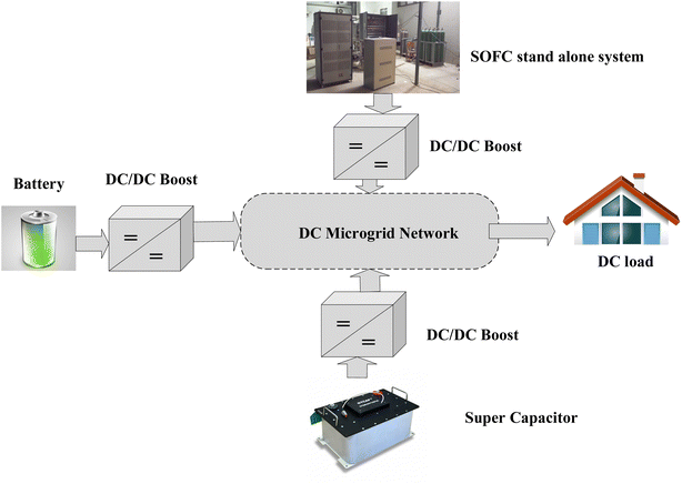
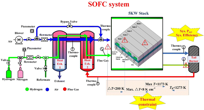
The overall structure and distribution of the hybrid SOFC-based DC microgrids system are shown in Fig. 1, which mainly consists of the SOFC stand-alone station, lithium battery, super capacitor, DC/DC boost converters, DC microgrids network, and DC load. The battery and supercapacitor have been preferred with the combinations because the SOFC system cannot reimburse for the fast load following,35,36 and the required transient power is supplied to the DC bus by the battery and supercapacitor. The DC/DC boost converters have been provided to maintain the quick-speed external load requirements and system reliability improving.37The systematic architecture of the SOFC stand-alone system is shown in Fig. 2. It mainly consists of two modules: the balance of plant (BOP) and SOFC stack. The BOP plays an auxiliary role in SOFC system generation, which mainly consists of the gas feed pipes and valves, secondary heat exchangers, and the tail gas recovery unit (burner). Then, the range of the stack operating power is about 1 kW to 6 kW in the different working conditions.
The stack anode side of the exhaust gas outlet contains a lot of unreacted fuel, which can be recycled into the SOFC system by the burner to increase fuel utilization. Meanwhile, an extra-second air bypass manifold is added to the SOFC system in order to prevent the excessive temperature in the stack.
Our early works have studied the structure of the SOFC system, simulation stratagem, parameter, and system-level optimization, and control strategies.38–42 The battery of Li_ion is considered in our paper since it has been proven with good energy density and electrical efficiency compared to the other energy modes. The supercapacitor is often known as the electric double-layer capacitor (EDLCs), which can charge and discharge more electrical energy because of its high capacitance. Then, their simulation process can be referred to in the work.43
Moreover, the input parameters of the related battery and supercapacitor model are shown in Table 1.
| Battery | Supercapacitor | ||
|---|---|---|---|
| Nominal voltage (V) | 28 | Rated capacitance (F) | 15.6 |
| Rated capacity (A h) | 6.6 | DC equivalent series resistance (ohms) | 2.1 × 10⁻³ |
| Maximum capacity (A h) | 40 | Rated voltage (V) | 16 |
| Fully charged voltage (V) | 32.42 | Surge voltage (V) | 18 |
| Nominal discharge current (A) | 17.4 | Number of series capacitor | 6 |
| Internal resistance (ohms) | 0.012 | Number of parallel capacitors | 1 |
| Capacity (A h) @ nominal voltage | 36.17 | Number of layers | 6 |
| Initial state-of-charge (%) | 90 | Molecular radius (m) | 4 × 10⁻¹⁰ |
| Battery voltage response time (s) | 30 | Operating temperature (°C) | 25 |
2.2 System identification
However, to ensure the effectiveness of the designed energy management, the static and dynamic characteristics of the core component (i.e., the stack) are identified. The static characteristic of the single fuel cell is conducted as follows: the single fuel cell with a size of 10 cm × 10 cm (Fig. 3(a)) under ideal conditions the experiment is conducted in an electrical furnace (Fig. 3(b)). The operating temperatures were set as 973 K. For this temperature case, the output power density and voltage were carefully monitored in the steady state, and then the electrical values were computed and recorded, as shown in Fig. 3(c). It is observed that the error between the Simulink model and experimental result increases slightly with decreasing the current density, especially the Nernst voltage of the single fuel cell of the simulation and experiment are 1.2 V and 1.18 V, respectively. Considering the electrical characteristics of the Simulink model are consistent with the experimental results in the working regions, where the current density is between 400 mA cm−2 and 1000 mA cm−2. In addition, it is seen that the Simulink model and experimental result of the power density may have a difference at a high current density region. The possible causes are mainly about a few aspects. First, the lower current (i.e. <100 mW cm−2) and power density mean the lower electrochemical reaction gas, which may correspond to less reaction time and operating time. Then, less operating time means less degradation and fewer volume changes.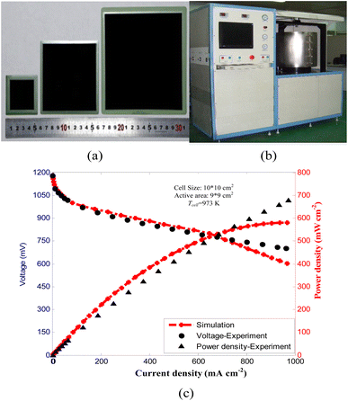 | ||
| Fig. 3 Steady state electrical characteristics test of fuel cells. (a) Single fuel cell; (b) test furnace; (c) steady-state electrical characteristics. | ||
Finally, along with the increase of the electrochemical reaction gas, the reaction time becomes longer, and the microstructure fixed parameters of the fuel cell (i.e. the fuel cell volume, surface area of the heat transfer, etc.) may change in comparison to the simulation parameters, therefore, the error may increase. In general, the SOFC model developed in this paper can well represents the static characteristics.
Moreover, the dynamic and static electrical characteristics can be conducted as follows. A 5-cell stack (Fig. 4(a)) was carried out in the electric furnace for 100 h. The load current started with 0 A, and gradually reached 80 A after 1.37 h. Afterward, it was always kept at a constant of 80 A. In this test, the use of the low reactant utilization is enough to retain a sufficient reactant flow rate circulating in each cell and so to avoid fuel exhaustion. During the test, the voltage of each cell has been measured and then saved by a cell voltage monitoring system. In addition, the temperature of each cell has been measured by five K-type thermocouples, respectively. Besides, a numbering convention was adopted to identify the cells in the stack in a manner like the levels in a building from bottom to top respectively: cell #1, cell #2, cell #3, cell #4, and cell #5, as shown in Fig. 4(b). It shows that the developed electrical coupling dynamic model is highly accurate. Above all, based on the electrical coupling dynamic model, an effective peripheral control system can be designed to manage the characteristics in the SOFC synchronously.
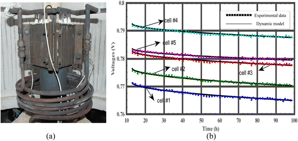 | ||
| Fig. 4 Dynamic electrical characteristics test of the fuel cells. (a) 5-cell stack; (b) dynamic electrical characteristics. | ||
3. Essential operational requirements
3.1 Input and output operational parameters
In order to adjust the temperature of the stack in real-time, it is necessary to pass the excessive air. Meanwhile, the air excess ratio (AR) denotes the direct relationship between the input air and hydrogen flow, so it can achieve the collaborative linkage in the system energy management. Moreover, fuel utilization (FU) is regulated to obtain the maximum electrical efficiency, thus FU is considered a key indicator that affects the generation efficiency of the system power, and then the current studies all hope to increase its upper limit. To quickly adjust the internal temperature of the stack and realize the optimization of the system efficiency, the real-time adjustment of the bypass valve opening ratio (BP) should be implemented. The system operating points have been described by the operating-variable combination (ISOFC, BP, AR, FU), and then the corresponding output performance of the SOFC system can be obtained for each operating point. The calculation formula is as follows.(1) Fuel utilization (FU)
From the basic operation of the SOFC system, it is known that four electrons are consumed for each mole of oxygen and two electrons for each mole of hydrogen. However, water has been produced at the rate of one mole for every two electrons. According to Faraday's law and electrochemical properties,44 for the hydrogen, the transferred charge is given by the amount of the hydrogen × 2F, or because the current is the change rate of the charge with respect to the time. The SOFC system has ‘n’ fuel cells, therefore the oxygen reaction rate, hydrogen reaction rate, and water reaction rate have the following relationship, which is given by44
 | (1) |
![[thin space (1/6-em)]](https://www.rsc.org/images/entities/char_2009.gif) 485 C mol−1.
485 C mol−1.
Then, the FU is given by
 | (2) |
(2) Air excess ratio (AR)
According to Faraday's law and electrochemical properties,44 the AR can be also given by
 | (3) |
(3) Bypass valve-opening ratio (BP)
 | (4) |
Thus, when the operating parameters of the FU, AR, and BP are presented, these flow regulation parameters of the power generation of the SOFC system can be expressed as follows.
The hydrogen molar flow rate ṄH2 is given by
 | (5) |
The air molar flow rate Ṅair is given by
 | (6) |
The air molar flow rate of the bypass Ṅair,by is given by
 | (7) |
The safe and controllable temperature is the prerequisite for the stable and long-life operation of the whole SOFC-based DC microgrid system. Considering the safe operating conditions of the SOFC system, the system set four thermal safety constraints, including the maximum operating temperature of the positive electrode–electrolyte-negative electrode (PEN), maximum PEN temperature gradient, the gas temperature difference of the stack inlet, and maximum burner temperature.
(1) Maximum PEN operating temperature max.TPEN
| Max.TPEN = max{TPEN(j)}, {j = 1, 2, …J − 1} | (8) |
In the process of building the single fuel cell models, for the spatial and temporal resolution, each single fuel cell is quasi-dimensionally discretized into five nodes (J = 5), as shown in Fig. 2. j is the index of the node in the flow direction, including the PEN tri-layer, interconnect plate, and the control volumes of the cathode and anode gas channel.
(2) Maximum PEN temperature gradient max.|ΔTPEN|
| Max.|TPEN| = max|TPEN(j + 1) − TPEN(j)|, {j = 1, 2, …J − 1} | (9) |
(3) Stack inlet temperature difference ΔTinlet
| ΔTinlet = |THE,air − THE,fuel| | (10) |
The temperature difference of the stack inlet is between the stack cathode (air side) and anode (fuel side). THE,air is the heat exchanger outlet temperature of the air side, and THE,fuel is the heat exchanger outlet temperature of the fuel side.
The optimal regulator in the SOFC-based DC microgrid mainly controls the demanded load power by referring to the SOFC system efficiency. Then, the efficiency of the SOFC stand-alone system can be defined as follows, which is given by
 | (11) |
 | (12) |
3.2 Operating variables indices
In addition to fast power tracking, operating safety (including thermal safety and avoiding fuel exhaustion) and high efficiency are the most important considerations for the control and optimization of energy management.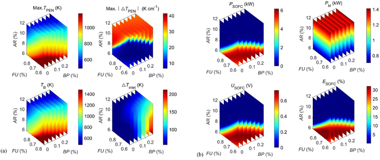 | ||
| Fig. 5 Static characteristics of the SOFC system. (a) Thermal characteristics; (b) electrical characteristics. | ||
(1) Stack of the SOFC-based DC microgrids current Is ∈ [10 A, 80 A].
(2) Bypass valve opening ratio BP ∈ [0, 0.3].
(3) Air excess ratio AR ∈ [6, 12].
(4) Fuel utilization FU ∈ [0.6, 0.9].
The principles of setting the upper and lower limits of the input operating parameters can be obtained from simulation analysis, which has been discussed in our previous studies.38,39
(1) Burner temperature TB ≤ 1273 K.
(2) PEN temperature max.TPEN ∈ [873 K, 1173 K].
(3) Maximum PEN temperature gradient max.|ΔTPEN| ≤ 8 K cm−1.
(4) Stack inlet temperature difference ΔTinlet ≤ 200 K.
All the range of the corresponding parameters is demonstrated according to the handbook (Fuel Cell Handbook 7th Edition), the experimental data, and the experimental platform in practice.
 | (13) |
In order to observe the fuel exhaustion conditions, the fuel concentration in the stacks must be observed in real-time. To ensure the fuel concentration in the stack XH2 > 0.
4. Energy management and optimization strategy
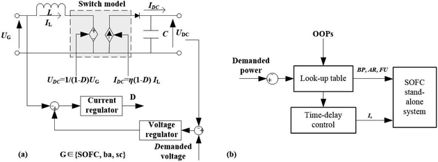
The response time of the output power of the SOFC-based DC/DC microgrid is within hundreds of seconds, which is insatiable for fast load tracking, especially, in scenarios of the external load power rising. In this section, the SOFC-based microgrid has been introduced to highlight the load power rising transients. In addition, comprehensively considering the thermal safety, high efficiency, and fuel exhaustion, the control and regular method of the energy management strategies for the proposed SOFC-based DC microgrid should be discussed.Thus, the schematic diagram of the energy management and optimization strategies for the SOFC-based DC microgrid has been proposed and shown in Fig. 7(a). For fast load following, thermal management, and high efficiency, the demanded DC voltage can be controlled by the voltage and current regulator through the associated boost converters of the SOFC stand-alone system, battery, and supercapacitor, respectively. Besides, the optimal regulator mainly controls the demanded load power by referring to the OOPs. Furthermore, three energy sources (i.e., the SOFC stand-alone system, battery, and supercapacitor) are introduced, and the complexity of the system energy control is increased. Then, the energy management strategy should be analysed to highlight the fast load following.
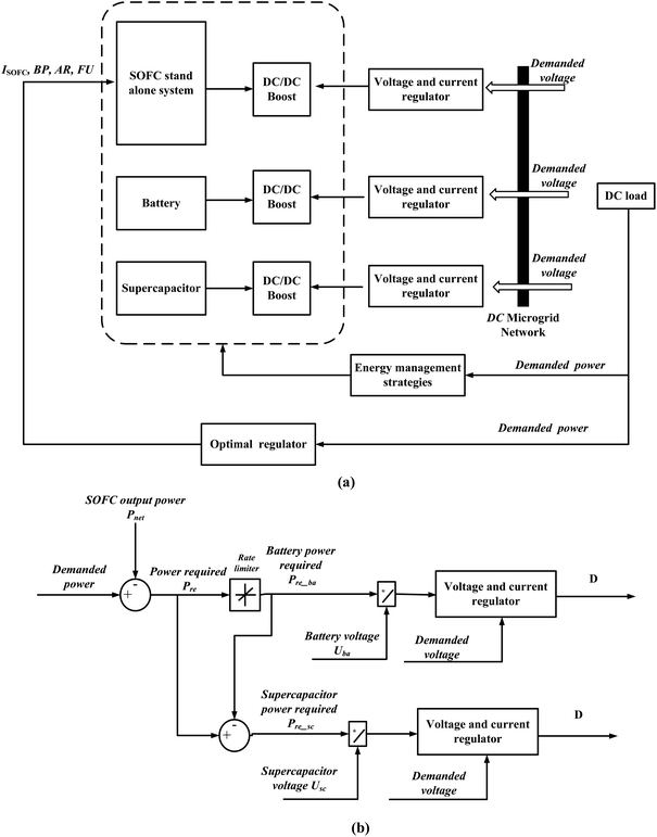 | ||
| Fig. 7 Energy management and optimization strategies. (a) The overall layout; (b) energy management strategies. | ||
4.1 Energy management
The proposed energy management strategy is shown in Fig. 7(b). The energy management of the SOFC system is designed based on net output power (Pnet) and demanded external load power (Pde). Thus, the difference between Pnet and Pde is the required whole power (Pre) during the external load power step-up, i.e.,| Pre = Pde − Pnet | (14) |
The battery and supercapacitor mainly provide the required energy. Then, we have
| Pre = Pre_ba + Pre_sc | (15) |
As the battery has a maximum charging and discharging rate, the required battery power is adopted by the power slope limitation, to make the output of the battery charging and discharging rate not change faster than the specified limit. Provided that the battery charging and discharging rate is Rba, which is given by
 | (16) |
Provided that the slew rate of the rising edge is R, the slew rate of the falling edge is F. Then, the piece-wise function is given by
 | (17) |
| Iba = Pre_ba/Uba | (18) |
| Isc = Pre_sc/Usc | (19) |
Thus, the voltage and current regulator was designed based on the above current and demanded voltage of the DC microgrid.
4.2 Voltage and current regulator
Fig. 8(a) shows the voltage and current regulator for the SOFC DC/DC converter. The DC/DC converter can allow voltage conversion as well as full control of the fuel cell current and DC bus voltage. For this study, the average value of the DC/DC converter models can be referred to the works.43–45 The PID control method is adopted in this paper to control the DC microgrid voltage near the enactment value.4.3 Optimal regulator
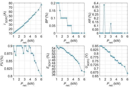
Moreover, as shown in Fig. 8(b), the system inputs, including the molar flow rate of the hydrogen input, the molar flow rate of the air input, current, and BP, are determined by the OOPs in the optimal regulator. OOPs can refer to the above results, as shown in Fig. 6.The fuel concentration in the SOFC system should be observed when the external load power increases since the fuel and air transfer delay time in the SOFC-based DC microgrid system is constant, provided that tdMFC1 = tdMFC2 = tdMFC3 in this paper. Our previous studies reveal that the current commands to the SOFC should be changed slowly for the safe transient operation to prevent fuel exhaustion. Thus, the time-delay control based on the SOFC current is adopted in this paper to prevent fuel starvation, which is given by
 | (20) |
5. Experimental results and analysis
Except for the steady operation of the SOFC-based DC microgrid, the fundamental purposes of the presented energy management and optimization strategy are to avoid fuel exhaustion, obtain maximum efficiency, and enhance the external load tracking capability; this section mainly analyses and discusses the related above-mentioned dynamic response properties. Provided that the delay time of the time-delay control is τ = 35 s, the delay time of three mass flow is tdMFC1 = tdMFC2 = tdMFC3 = 1 s, the demanded voltage of the DC microgrid is 220 V, and the demanded external load power step from 1 kW → 3 kW → 4.5 kW → 5.5 kW.5.1 Fast load tracking
The power results for energy management strategies are shown in Fig. 9. Fig. 9(a) shows the power response of the SOFC power and DC power. DC power represents the external load tracing. Experimental results show that the SOFC stand-alone system takes hundreds of seconds to meet the demanded external load power. Whereas, using the proposed energy management strategies, the output power of the DC microgrid can respond within seconds to meet the external load requirements. According to the system required power (Fig. 9(a)), the battery (Fig. 9(c)), and supercapacitor power (Fig. 9(d)) are well provided timely to supply the required electric energy.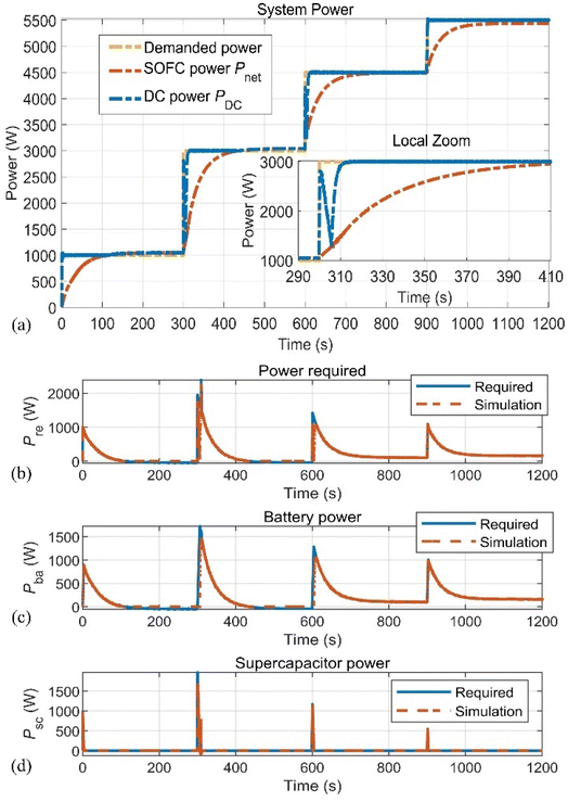 | ||
| Fig. 9 Power results for energy management strategies. (a) Demanded power, SOFC power, and DC power; (b) required power; (c) battery power; (d) supercapacitor power. | ||
5.2 Optimal operating condition
Fig. 10 shows and analyses the optimal operating conditions for the proposed energy management and optimization strategy, including the efficiency, current, and voltage of the SOFC system. As shown in Fig. 10(a), the demanded external load power of the SOFC-based DC microgrid step from 1 kW → 3 kW → 4.5 kW → 5.5 kW, the SOFC system efficiency varies accordingly and then ultimately reaches the stable state of the corresponding demanded power. The current (Fig. 10(b)) and voltage (Fig. 10(c)) of the SOFC system shows a similar response to the efficiency response. Moreover, using the proposed optimization strategy, the SOFC-based DC microgrid can operate under optimal conditions after reaching a steady state, especially, since the SOFC system shows relatively high efficiency. The optimal operating point of the different working powers in the steady state is shown in the embedded small figure. It should be pointed out that the optimal operating points have been demonstrated and discussed in Fig. 6.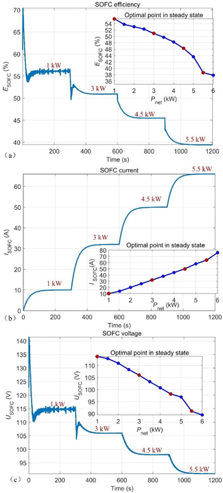 | ||
| Fig. 10 Optimal operating conditions. (a) SOFC system efficiency; (b) SOFC current; (c) SOFC voltage. | ||
5.3 Thermal safety
The performance of the related thermal results in the SOFC-based DC microgrid is shown in Fig. 11 with the thermal characteristics of all the changes with the demanded external load. Fig. 11 shows that the maximum PEN temperature and its gradient, burner temperature, and SOFC stack inlet temperature are all within their thermal safety range. All the results indicate that the proposed energy management strategies can ensure thermal safety during power switching.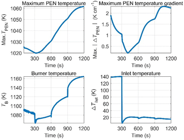 | ||
| Fig. 11 Thermal response, including the maximum PEN temperature, maximum PEN temperature gradient, burner temperature and stack inlet temperature. | ||
5.4 Fuel starvation
Fig. 12 shows the fuel concentration and power response of the SOFC system when the delay times of the time-delay controller are τ = 25 s, 35 s, 55 s, and 75 s. Fig. 12(a) shows the molar fraction of outlet H2, it demonstrates that the shorter the delay time, the smaller the molar fraction of the outlet H2, and finally more prone to fuel exhaustion. The root cause of this phenomenon is that the time-delay controlling influence is weakened with the decrease in the delay time. Especially, XH2 = 0 when the delay time τ = 25 s, which demonstrates that fuel exhaustion occurs. The corresponding power response is shown in Fig. 12(b), it shows that the longer the delay time, the longer the response time, which is undesirable for following the rapid loading. Because the SOFC current changes slowly to avoid fuel starvation, the power response speed is slowed. Hence, avoiding fuel exhaustion is in direct competition with the rapid loading following, therefore the delay time of the time-delay controller should be set up from the comprehensive consideration of the above two points.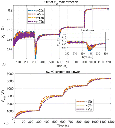 | ||
| Fig. 12 Fuel concentration and power. (a) The molar fraction of the outlet H2; (b) net power of the SOFC system. | ||
5.5 Related electrical results
Fig. 13 shows the related electrical results in the SOFC-based DC microgrid, which includes the battery, the supercapacitor, and DC microgrid load. The voltage and current of the battery (Fig. 13(a)) and the supercapacitor (Fig. 13(b)) are well controlled to cover the shortage of the SOFC stand-alone system in the energy supply. Especially, the DC microgrid voltage is one of the most important factors influencing the stability of the external load; Fig. 13(c) shows the DC microgrid voltage is well controlled to 220 V, and the DC microgrid current varies according to the external load power switching.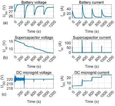 | ||
| Fig. 13 Related electrical results in the SOFC-based DC microgrid. (a) Battery; (b) supercapacitor; (c) DC microgrid load. | ||
6. Conclusion
This paper presented the energy management strategies for the hybrid SOFC-based DC microgrids from the perspective of high efficiency, operating safety, and transient response. The architectures of the hybrid SOFC-based DC microgrid system, mainly including the SOFC, lithium battery, and supercapacitor have been established. Then, the system's essential operational requirements were analysed and discussed, including the input and output operational parameters and operating variables indices (i.e., the operating parameters, thermal safety, fuel exhaustion, and maximum system efficiency). Considering the high efficiency, steady-state thermal safety, and load tracing, the optimization and energy management strategies to highlight the fast load following the hybrid SOFC-based DC microgrid are proposed, which mainly includes the energy management, voltage, and current regulator, as well as the optimal regulator. As expected, the favourable power response time is achieved within seconds because the battery and supercapacitor can remedy the defects of the slow SOFC power transients. Thus, the contribution of this paper is shown as follows. (1) Except for the rapid load following, fuel starvation, high efficiency, and thermal safety have been first considered in the proposed energy management strategy, which further improves the performances of the SOFC system. (2) The OOPs have been applied to the energy management strategies, which would obtain the maximum efficiency and thermal safe operating when the proposed SOFC system reaches the steady state. (3) The fast power transient's controller considering the fuel starvation and thermal safety was comprehensively designed, which can lead to the development of high-efficiency monitoring and optimization of energy management.To conclude, the hybrid SOFC-based DC microgrid has great superiority in fast load tracing, especially when the external power steps up. An alternative is to design multi-objective optimization energy management strategies to optimize all the performance criteria in the hybrid SOFC-based DC microgrid, which is the next topic for our further studies.
Author contributions
Lin Zhang: conceptualization, investigation, methodology, validation, software, data curation, formal analysis, and writing – original draft. Hongtu Xie and Guoqian Wang: conceptualization, investigation, data curation, formal analysis, funding acquisition, resources, and writing – original draft. Quanmin Niu and Feng Wang: supervision, project administration, resources, and funding acquisition. Chao Xie: formal analysis, visualization, and writing – review and editing.Conflicts of interest
All the authors declare that they have no known competing financial interests or personal relationships that could have appeared to influence the work reported in this paper. Thus, there are no conflicts to declare.Acknowledgements
This work is co-supported by the Guangdong Basic and Applied Basic Research Foundation (Grant No. 2021A1515010768), the Shenzhen Science and Technology Program (Grant No. 202206193000001, 20220815171723002), the National Natural Science Foundation of China (Grant No. 62203465, No. 62001523 and No. 6210593), the Science and Technology Talents Foundation of Air Force Early Warning Academy (Grant No. 2021KJY11), the Science and Technology on Near-surface Detection Laboratory Pre-Research Foundation (Grant No. 6142414200607), and the Natural Science Foundation of Guangdong Province (Grant No. 202214050002344). Lin Zhang, Hongtu Xie, and Guoqian Wang are the first co-authors, and Hongtu Xie and Guoqian Wang are corresponding co-authors.References
- A. Eid, Utility integration of PV-wind-fuel cell hybrid distributed generation systems under variable load demands, Int. J. Electr. Power Energy Syst., 2014, 62, 689–699 CrossRef.
- M. Srinivasan and A. Kwasinski, Control analysis of parallel DC-DC converters in a DC microgrid with constant power loads, Int. J. Electr. Power Energy Syst., 2020, 122(1–9), 106207 CrossRef.
- Y. Han, L. Y. Li, W. R. Chen, Y. J. Hou and J. F. Zhang, A bi-cyclic co-optimization method for sizing of electricity-hydrogen hybrid energy storage microgrid, Sustainable Energy Fuels, 2022, 6, 4048–4061 RSC.
- H. T. Xie, X. Q. Jiang, X. Hu, Z. T. Wu, G. Q. Wang and K. Xie, High-efficiency and low-energy ship recognition strategy based on spiking neural network in SAR images, Front. Neurorobot., 2022, 16(1–16), 970832 CrossRef PubMed.
- L. C. Xu, A. V. Ibragimova and K. I. Shilova, Analysis of international practice in the use of renewable energy sources (RES), IOP Conf. Ser.: Earth Environ. Sci., 2022, 979(1–6), 012188 Search PubMed.
- P. Sapkota, C. Boyer, R. Dutta, C. Cazorla and K.-F. Aguey-Zinsou, Planar polymer electrolyte membrane fuel cells: powering portable devices from hydrogen, Sustainable Energy Fuels, 2020, 4, 439–468 RSC.
- J. H. Zhang, Y. H. Jin, J. B. Liu, Q. Q. Zhang and H. Wang, Recent advances in understanding and relieving capacity decay of lithium ion batteries with layered ternary cathodes, Sustainable Energy Fuels, 2021, 5, 5114–5138 RSC.
- T. C. Mendes, F. L. Zhou, A. J. Barlow, M. Forsyth, P. C. Howlett and D. R. MacFarlane, An ionic liquid based sodium metal-hybrid supercapacitor-battery, Sustainable Energy Fuels, 2018, 2, 763–771 RSC.
- D. S. Dhawale, A. Ali and A. C. Lokhande, Impact of various dopant elements on the properties of kesterite compounds for solar cell applications: a status review, Sustainable Energy Fuels, 2019, 3, 1365–1383 RSC.
- V. Goldstein, M. K. Rath, A. Kossenko, N. Litvak, A. Kalashnikov and M. Zinigrad, Solid oxide fuel cells for ammonia synthesis and energy conversion, Sustainable Energy Fuels, 2022, 6, 4706–4715 RSC.
- Y. M. Wang, S. Q. Li, H. W. Sun, C. Y. Huang and N. Youssefi, The utilization of adaptive African vulture optimizer for optimal parameter identification of SOFC, Energy Rep., 2022, 8, 551–560 CrossRef.
- S. Mumtaz, L. Khan, S. Ahmed and R. Badar, Indirect adaptive soft computing based wavelet-embedded control paradigms for WT/PV/SOFC in a grid/charging station connected hybrid power system, PLoS One, 2018, 13(4), 1–4 CrossRef PubMed.
- P. Rathod, S. K. Mishra and S. K. Bhuyan, Renewable energy generation system connected to micro grid and analysis of energy management: a critical review, Int. J. Power Electron. Drive Syst., 2022, 13(1), 470–479 Search PubMed.
- M. Sorrentino, C. Pianese and Y. G. Guezennec, A hierarchical modeling approach to the simulation and control of planar solid oxide fuel cells, J. Power Sources, 2008, 180(1), 380–392 CrossRef CAS.
- H. B. Huo, Y. X. Wu, Y. Q. Liu, S. H. Gan and X. H. Kuang, Control-oriented nonlinear modeling and temperature control for solid oxide fuel cell, J. Fuel Cell Sci. Technol., 2010, 7(4), 0410051–0410059 CrossRef.
- S. A. Hajimolana, S. M. Tonekabonimoghadam, M. A. Hussain, M. H. Chakrabarti, N. S. Jayakumar and M. A. Hashim, Thermal stress management of a solid oxide fuel cell using neural network predictive control, Energy, 2013, 62(1), 320–329 CrossRef CAS.
- S. L. Huang, C. Yang, H. Chen, N. Zhou and D. Tucker, Coupling impacts of SOFC operating temperature and fuel utilization on system net efficiency in natural gas hybrid SOFC/GT system, Case Stud. Therm. Eng., 2022, 31, 101868 CrossRef.
- P. F. Zhu, Z. Wu, L. L. Guo, J. Yao, M. Dai and J. W. Ren, et al., Achieving high-efficiency conversion and poly-generation of cooling, heating, and power based on biomass-fueled SOFC hybrid system: performance assessment and multi-objective optimization, Energy Convers. Manage., 2021, 240(15), 114245 CrossRef CAS.
- P. F. Zhu, J. Yao, C. H. Qian, F. S. Yang, E. Porpatham and Z. X. Zhang, et al., High-efficiency conversion of natural gas fuel to power by an integrated system of SOFC, HCCI engine, and waste heat recovery: thermodynamic and thermo-economic analyses, Fuel, 2020, 275(1), 117883 CrossRef CAS.
- L. Z. Tan, X. M. Dong, Z. Q. Gong and M. T. Wang, Analysis on energy efficiency and CO2 emission reduction of an SOFC-based energy system served public buildings with large interior zones, Energy, 2018, 165(part B), 1106–1118 CrossRef.
- Q. Li, P. R. Liu, X. Meng, G. R. Zhang, Y. X. Ai and W. R. Chen, Model prediction control-based energy management combining self-trending prediction and subset-searching algorithm for hydrogen electric multiple unit train, IEEE Trans. Transp. Electrif., 2022, 8, 2249–2260 Search PubMed.
- R. Kandepu, L. Imsland, B. A. Foss, C. Stiller, B. Thorud and O. Bolland, Modeling and control of a SOFC-GT-based autonomous power system, Energy, 2007, 32(4), 406–417 CrossRef CAS.
- X. S. Wang, X. J. Lv, X. C. Mi, C. Spataru and Y. W. Weng, Coordinated control approach for load following operation of SOFC-GT hybrid system, Energy, 2022, 248, 123548 CrossRef CAS.
- Q. Li, X. Meng, F. Gao, G. R. Zhang, W. R. Chen and K. Rajashekara, Reinforcement learning energy management for fuel cell hybrid system: a review, IEEE Ind. Electron. Mag., 2022, 2, 2–11 Search PubMed.
- B. Ghorbani and K. Vijayaraghavan, Developing a virtual hydrogen sensor for detecting fuel starvation in solid oxide fuel cells using different machine learning algorithms, Int. J. Hydrogen Energy, 2020, 45(51), 27730–27744 CrossRef CAS.
- G. Brus, K. Miyoshi, H. Iwai, M. Saito and H. Yoshida, Change of an anode's microstructure morphology during the fuel starvation of an anode-supported solid oxide fuel cell, Int. J. Hydrogen Energy, 2015, 40(21), 6927–6934 CrossRef CAS.
- H. sharma and O. P. Jaga, Modeling and control strategies for energy management system in electric vehicles, Perspect. Sci., 2016, 8, 358–360 CrossRef.
- H. El Fadil, F. Giri, J. M. Guerrero and A. Tahri, Modeling and nonlinear control of a fuel cell/supercapacitor hybrid energy storage system for electric vehicles, IEEE Trans. Veh. Technol., 2014, 63(7), 3011–3018 Search PubMed.
- J. G. Han, J.-F. Charpentier and T. H. Tang, An energy management system of a fuel cell/battery hybrid boat, Energies, 2014, 7, 2799–2820 CrossRef.
- W. B. Zhang, J. Q. Li, L. F. Xu and M. Ouyang, Optimization for a fuel cell/battery/capacity tram with equivalent consumption minimization strategy, Energy Convers. Manage., 2017, 134, 59–69 CrossRef CAS.
- Q. Li, X. Meng, F. Gao, G. R. Zhang and W. R. Chen, Approximate cost-optimal energy management of hydrogen electric multiple unit trains using double Q-learning algorithm, IEEE Trans. Ind. Electron., 2022, 69, 9099–9110 Search PubMed.
- G. S. Thirunavukkarasu, M. Seyedmahmoudian, E. Jamei, B. Horan, S. Mekhilef and A. Stojcevski, Role of optimization techniques in microgrid energy management systems—a review, Energy Strategy Rev., 2022, 43, 100899 CrossRef.
- B. Hegde, Q. Ahmed and G. Rizzoni, Energy saving analysis in electrified powertrain using look-ahead energy management scheme, Appl. Energy, 2022, 325, 119823 CrossRef.
- H. Aouzellag, B. Amrouche, K. Iffouzar and D. Aouzellag, Proposed hysteresis energy management strategy based on storage system efficiency for hybrid electric vehicle, J. Energy Storage, 2022, 54, 105259 CrossRef.
- O. A. Ahmed and J. A. M. Bleijs, Power flow control methods for an ultra-capacitor bidirectional converter in DC microgrids–a comparative study, Renewable Sustainable Energy Rev., 2013, 26, 727–738 CrossRef.
- Z. W. Liu, J. Q. Zhao and Z. Q. Zou, Impedance modeling, dynamic analysis and damping enhancement for DC microgrid with multiple types of loads, Int. J. Electr. Power Energy Syst., 2020, 122, 106183 CrossRef.
- H. Armghan, M. Yang, M. Q. Wang, N. Ali and A. Armghan, Nonlinear integral backstepping based control of a DC microgrid with renewable generation and energy storage systems, Int. J. Electr. Power Energy Syst., 2020, 117, 105613 CrossRef.
- L. Zhang, X. Li, J. H. Jiang, S. H. Li, J. Yang and J. Li, Dynamic modeling and analysis of a 5-kW solid oxide fuel cell system from the perspectives of cooperative control of thermal safety and high efficiency, Int. J. Hydrogen Energy, 2015, 40, 456–476 CrossRef CAS.
- L. Zhang, J. H. Jiang, H. Cheng, Z. H. Deng and X. Li, Control strategy for power management, efficiency-optimization and operating-safety of a 5 kW solid oxide fuel cell system, Electrochim. Acta, 2015, 177, 237–249 CrossRef CAS.
- L. Zhang, S. Y. Shi, J. H. Jiang, F. Wang, H. T. Xie and H. Chen, et al., An optimization and fast load-oriented control for current-based solid oxide fuel cell system, J. Solid State Electrochem., 2018, 22(9), 2863–2877 CrossRef CAS.
- L. Zhang, S. Y. Shi, J. H. Jiang and X. Li, Current-based MPC for operating-safety analysis of a reduced-order solid oxide fuel cell system, Ionics, 2019, 25(4), 1759–1772 CrossRef CAS.
- L. Zhang, W. H. Tang, F. Wang, C. Xie, W. B. Zhou and H. T. Xie, Optimization and control for solid oxide fuel cell system hybrid DC microgrids from the perspective of high efficiency, thermal safety, and transient response, Front. Energy Res., 2022, 10, 953082 CrossRef.
- O. Tremblay, L.-A. Dessaint and A.-I. Dekkiche, A generic battery model for the dynamic simulation of hybrid electric vehicles, IEEE Veh. Power Propuls. Conf., 2007, 284–289 Search PubMed.
- U. K. Chakraborty, An error in solid oxide fuel cell stack modelling, Energy, 2011, 36, 801–802 CrossRef.
- N. E. Zakzouk, A. K. Khamis, A. K. Barry and W. Williams, Continuous-input continuous-output current buck-boost DC/DC converters for renewable energy applications: Modelling and performance assessment, Energies, 2019, 12(11), 2208 CrossRef CAS.
Footnote |
| † These authors share the first authorship and have contributed equally to this work. |
| This journal is © The Royal Society of Chemistry 2023 |

