Construction of core–shell Ni–Co(OH)F@NiCo2S4 nanorods for highly efficient hydrazine-assisted hydrogen evolution†
Yongli
Dong‡
 a,
Pei
Wang‡
a,
Jun-Ye
Zhang‡
b,
Weina
Song
a,
Pei
Wang‡
a,
Jun-Ye
Zhang‡
b,
Weina
Song
 *a,
Yan
Chen
b,
Fan
Wang
a,
Yamin
Liu
a,
Chuanbiao
Zhu
a and
Wei
Li
 *b
*b
aSchool of Environmental and Chemical Engineering, Heilongjiang University of Science and Technology, Harbin 150022, PR China. E-mail: weinasong@163.com
bDepartment of Chemistry, Fudan University, Shanghai 200433, PR China. E-mail: weilichem@fudan.edu.cn
First published on 16th November 2022
Abstract
Electrochemical hydrazine-assisted water electrolysis is an effective strategy for hydrogen production. However, the great energy consumption of electrolysis is still a challenge, which imperatively needs the rational design of highly efficient electrocatalysts. Herein, the synthesis of novel Ni–Co(OH)F@NiCo2S4 nanorods is reported via the hydrothermal method and subsequent controllable sulphuration process. The Ni–Co(OH)F@NiCo2S4 nanorods are composed of Ni–Co(OH)F cores (∼70 nm diameter) and NiCo2S4 shells (∼65 nm thickness). The experiments confirm that Ni doping and core–shell interface engineering can synergistically accelerate electron transfer, optimize the H adsorption/desorption behaviors, and thus boost the catalytic performance in hydrazine-assisted hydrogen evolution. The resultant Ni–Co(OH)F@NiCo2S4 nanorods show a low overpotential (η10 = 97 mV) and small Tafel slope (58 mV dec−1) for alkaline hydrogen evolution. Besides, the Ni–Co(OH)F@NiCo2S4 nanorods can output 10 mA cm−2 current density for the hydrazine oxidation reaction at working potentials of 20 mV (0.1 M hydrazine and 1.0 M KOH) and −49 mV (1.5 M hydrazine and 1.0 M KOH), respectively. An ultralow cell voltage of 250 mV is required to achieve a current density of 10 mA cm−2 in a hydrazine-assisted hydrogen evolution system.
The energy crisis is driving the international community to focus on developing greener energy sources.1 Hydrogen energy, especially that obtained from electrochemical water splitting, is a particularly promising energy carrier.2–4 However, electrochemical hydrogen production currently still requires a large drive voltage and high energy consumption.5,6 As known, electrochemical water splitting contains two half-reactions: the cathodic hydrogen evolution reaction (HER) and anodic sluggish oxygen evolution reaction (OER).7,8 Recently, it has been reported that hydrazine-assisted hydrogen production cells can produce hydrogen at a low drive voltage by using the anodic hydrazine oxidation reaction (HzOR) to replace the kinetically sluggish OER.9–11 In order to minimize the energy consumption, there is still a need to design efficient catalysts with excellent electrocatalytic performance.12,13 Although noble metal-based catalysts have shown moderate H adsorption/desorption behaviors and high catalytic activities, their scarcity and high price seriously hinder their large-scale industrial application.14,15 Thus, earth-abundant and low-cost transition metal-based materials, such as metal sulfides, metal phosphides and metal nitrides, have attracted intensive attention.16 Among them, metal sulfides, especially, cobalt sulfides are regarded as one of the most promising catalysts due to their variable valence and highly active sites for the HER. For example, in the study of Yan, Ao, Feng and co-workers, cobalt sulfides have been reported to exhibit overpotentials of 138, 124 and 175 mV for the HER, respectively.17–19 Nevertheless, cobalt sulfides also have some disadvantages, for instance, poor stability, large overpotential and low conductivity, which severely limit their application in the HER. Therefore, it is necessary to further optimize the adsorption properties for hydrogen and conductivity of cobalt sulfides for better HER applications.
Nowadays, many strategies have been developed to boost the catalytic activity, such as heteroatom doping, interface engineering, defect engineering, heterostructure engineering and so on.20–23 Among them, heteroatom doping is widely used as an effective method because it can optimize the electronic structure and H adsorption/desorption behaviors of catalysts. For instance, Wang et al. demonstrated that the doping of Ni atoms can adjust the adjacent coordination environment and local electronic structure, thus optimizing the intrinsic H adsorption/desorption behaviors.20 On the other hand, interface engineering is another feasible way to accelerate reaction kinetics via a multi-site catalysis process.24,25 In particular, interface effects between sulfides and oxides could modulate the interfacial electronic state and optimize the H adsorption/desorption behaviors.26,27 For example, Zhai et al. reported that heterointerfaces in electrocatalysts can effectively improve the catalytic performance and a NiMoOx/NiMoS heterostructure array shows a 38 mV overpotential for hydrogen evolution at 10 mA cm−2.28 Wu et al. prepared a NF–C/CoS/NiOOH core–shell heterostructure with a hierarchical nanosheet structure and high HER performance, which exhibits an overpotential of 170 mV at a current density of 10 mA cm−2.29 Based on the studies mentioned above, it was found that an effective combination of heteroatom doping and interfacial effects is promising to enable catalysts with more flexible modulation of conductivity and H adsorption/desorption behaviors, so as to obtain better HER performance. However, to the best of our knowledge, the synergy of Ni doping and interface engineering is full of challenges and rarely reported, though it is imperative and promising.
Herein, the core–shell Ni–Co(OH)F@NiCo2S4 nanorods are synthesized via the hydrothermal and subsequent controllable sulphuration processes. Notably, the Ni–Co(OH)F@NiCo2S4 nanorods not only contained exposed synergistic sites that may promote the alkaline HER/HzOR kinetics, but also constructed core–shell structures with active interfaces. Due to Ni doping and interface engineering, the core–shell Ni–Co(OH)F@NiCo2S4 nanorods exhibit more efficient electron transfer and superior H adsorption/desorption behaviors. Ni doping together with the core–shell interface effect synergistically optimizes the H adsorption/desorption behaviors, effectively promotes charge transfer in the electrocatalytic process, and greatly improves the electrocatalytic performance. Specifically, only 97 mV overpotential of the HER is required to achieve 10 mA cm−2 over the core–shell Ni–Co(OH)F@NiCo2S4 nanorods. Meanwhile, the Ni–Co(OH)F@NiCo2S4 nanorods have also exhibited excellent HzOR activity with a low potential of −49 mV (vs. RHE) to deliver a current density of 10 mA cm−2, which is better than that of most of the reported cobalt-based/selenide-based electrocatalysts.30–32 This work not only offers a Ni–Co(OH)F@NiCo2S4 core–shell nanorod electrocatalyst for a hydrazine hydrate-assisted hydrogen evolution system, but more importantly, proposes a strategy combining heteroatom doping and interface engineering to improve electrocatalytic performance, thus providing a cutting-edge example for design and preparation of highly efficient electrocatalysts in the future.
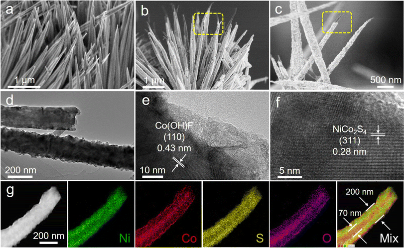
The Ni–Co(OH)F@NiCo2S4 core–shell nanorods were fabricated via the hydrothermal and subsequent controllable sulphuration processes (Scheme 1). Specifically, a Ni–Co(OH)F core was initially formed through a hydrothermal treatment, and after chemical vapor deposition (CVD) sulphuration at 350 °C under a He atmosphere, the as-designed Ni–Co(OH)F@NiCo2S4 nanorods consisting of a Ni–Co(OH)F core and NiCo2S4 shell were obtained. Scanning electron microscopy (SEM) images of Ni–Co(OH)F precursors demonstrate that a large number of Ni–Co(OH)F nanorods are well arrayed on the nickel foam substrate (Fig. S1†), and these nanorods possess a uniform smooth surface with a needle-like tip morphology (Fig. 1a). Further observation (Fig. 1b) reveals that the morphology of Ni–Co(OH)F precursors changed obviously after the sulphuration process. The obtained Ni–Co(OH)F@NiCo2S4 sample displays rough exterior surfaces, owing to the formation of a sulfide shell layer that wraps around the Ni–Co(OH)F nanorod core. Furthermore, the interior Ni–Co(OH)F is exposed at the top of nanorods, which proves the formation of a unique core–shell structure of Ni–Co(OH)F@NiCo2S4 nanorods (Fig. 1c). In addition, the Co(OH)F@CoS2 reference sample without Ni doping also exhibits a nanorod morphology (Fig. S2†). The transmission electron microscopy (TEM) image (Fig. 1d) corroborates that the internal part of Ni–Co(OH)F@NiCo2S4 nanorods is a solid, and the nanorod diameter is about 200 nm. As shown in Fig. 1e, the well-defined crystal lattice of 0.42 nm corresponds to the (110) facet of Ni–Co(OH)F. As for the exterior shell, the lattice fringe of 0.28 nm is ascribed to the (311) facet of NiCo2S4 (Fig. 1f). These results further suggest the construction of unique core–shell heterostructure Ni–Co(OH)F@NiCo2S4 nanorods. Moreover, the EDS elemental mapping images (Fig. 1g) reveal that there are massive nickel and sulfur signals, as well as small amounts of cobalt and oxygen signals in the external shell. Meanwhile, the cobalt and oxygen signals are distributed mostly in the internal area with slight nickel and sulfur signals. In particular, the mixed element picture further confirms the Ni–Co(OH)F@NiCo2S4 nanorods with a unique core–shell heterostructure.
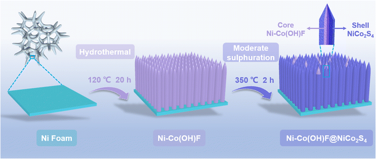 | ||
| Scheme 1 Schematic illustration of the fabrication process of Ni–Co(OH)F@NiCo2S4 core–shell nanorods. | ||
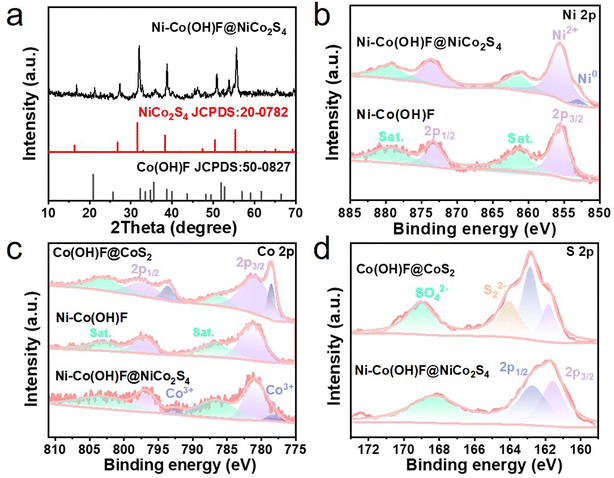
To uncover the crystal phase information of core–shell Ni–Co(OH)F@NiCo2S4 nanorods, the X-ray diffraction (XRD) patterns were recorded (Fig. 2a). The typical peaks of (220), (311), (400), (511) and (440) crystal planes of NiCo2S4 (JCPDS: 73-1704) are identified at 26.84, 31.58, 38.32, 55.46 and 55.3°, respectively. The peaks at 20.84, 35.56 and 51.94° correspond to the (110), (111) and (221) crystal planes of the orthogonal structure (JCPDS: 50-0827) of Ni–Co(OH)F, respectively. This suggests that the prepared Ni–Co(OH)F@NiCo2S4 nanorod is well crystalline without impurities. Meanwhile, in order to clarify the influence of Ni doping and the core–shell interface effect, Co(OH)F@CoS2 and NiCo2S4 reference samples were also prepared, the XRD patterns of which are presented (Fig. S3 and S4†).
The X-ray photoelectron spectroscopy (XPS) technique was employed to detect the surface valence states of the electrocatalysts. The XPS survey spectra of Ni–Co(OH)F and Ni–Co(OH)F@NiCo2S4 samples (Fig. S5†) confirm the presence of Ni, Co, S, F and O, while no Ni appears in Co(OH)F@CoS2 nanorods. In the Ni 2p region (Fig. 2b), four characteristic peaks of Ni–Co(OH)F@NiCo2S4 are separated into two groups: one is attributed to Ni(II) 2p3/2, containing a main peak at 855.6 eV with a satellite peak at 861.4 eV; another group, which has a higher binding energy, corresponding to Ni(II) 2p1/2, similarly composed of a main peak (873.6 eV) and satellite peak (879.3 eV).9 Of special note is that the signal peak shown at 853.0 eV is attributed to low-valence Ni, which may possess a mediocre adsorption ability for hydrogen atoms.33 Moreover, the presence of low-valence Ni might enhance the conductivity of Ni–Co(OH)F@NiCo2S4 nanorods,33 which could play a certain role in the charge transfer of the shell structure. In contrast to heterostructure Ni–Co(OH)F@NiCo2S4, the low-valence Ni signal is not shown in the Ni 2p XPS spectra of Ni–Co(OH)F, which implies that low-valence Ni is produced during the subsequent controllable sulphuration process. Co 2p XPS spectra (Fig. 2c) show that the Co(II) state has four peaks, among which the peak values at 781.0 and 797.1 eV are assigned to Co(II) 2p3/2 and Co(II) 2p1/2, and the peaks at 786.0 and 803.4 eV correspond to satellites.26 It is noted that the peaks of Co(III) 2p3/2 and Co(III) 2p1/2 can also be seen at 778.0 and 792.7 eV, respectively.19 Compared with Ni–Co(OH)F, the appearance of Co3+ and the negative shifts of the peaks in Ni–Co(OH)F@NiCo2S4 indicate that the electron density around the Co site increases, which can be attributed to the interaction of the core and shell.26,34,35 However, the characteristic peaks of Co3+ in the Co(OH)F@CoS2 reference sample are significantly higher than that of Ni–Co(OH)F@NiCo2S4, implying that the doping of Ni affects the valence state of Co species.36 The O 1s characteristic peak of Ni–Co(OH)F@NiCo2S4 is shifted towards higher and lower binding energies relative to Ni–Co(OH)F and Co(OH)F@CoS2, respectively (Fig. S6†). For Co(OH)F@CoS2 and NiCo2S4, the S 2p spectra (Fig. 2d) exhibit two normal peaks at 161.5 and 162.8 eV, related to S 2p3/2 and S 2p1/2, respectively.37 Notably, surface oxidation is substantiated by the SO42− signal, which is unveiled at 168.2 eV. The other peak at 164.1 eV for Co(OH)F@CoS2 indicates the existence of bridging S22−.37 Here, it can be concluded that Ni doping and core–shell heterostructures adjust the valence states of the Ni–Co(OH)F@NiCo2S4 nanorods, whilst there was a strong electron interaction between the Ni–Co(OH)F core and NiCo2S4 shell, which would promote an effective electron transfer at the core–shell heterogeneous interface.
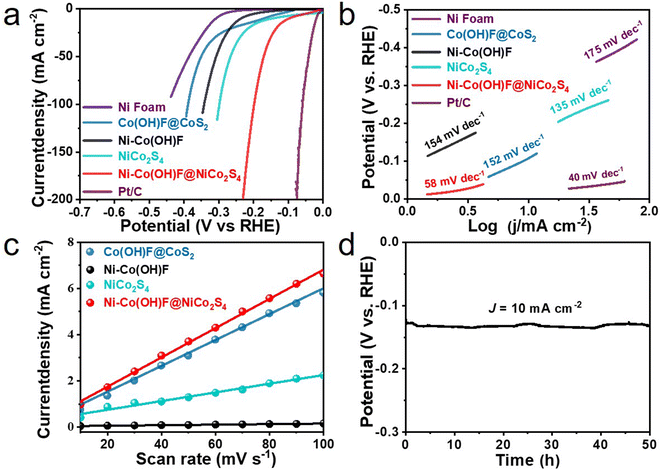
The alkaline HER activity was tested in a three-electrode system with 1.0 M KOH electrolyte. A graphite rod was applied as the counter electrode. Moreover, the iR-compensated linear sweep voltammogram (LSV) curves of all samples are collected (Fig. 3a), including Ni foam, Ni–Co(OH)F, Ni–Co(OH)F@NiCo2S4, NiCo2S4, Co(OH)F@CoS2 and commercial Pt/C catalysts. Nickel foam shows the worst activity, which needs an overpotential of 300 mV to give a current density of 10 mA cm−2. In comparison with Ni–Co(OH)F and Co(OH)F@CoS2, Ni–Co(OH)F@NiCo2S4 heterostructure nanorods evidently show higher activity for the HER; their overpotential is merely 97 mV, which is much better than those of other reported materials (Table S1 and Fig. S7†). In addition, NiCo2S4 nanorods exhibit a relatively low overpotential of 147 mV, but still higher than that of the Ni–Co(OH)F@NiCo2S4 heterostructure, highlighting that the Ni–Co(OH)F core also enacts an important role. As known, the Tafel slope is intimately related to reaction rate/kinetics.38 The Tafel slopes of various samples are presented to evaluate reaction activity (Fig. 3b). Obviously, commercial Pt/C has the lowest Tafel slope (40 mV dec−1), due to its ultrafast reaction kinetics. Compared with Co(OH)F@CoS2, Ni–Co(OH)F and NiCo2S4 reference samples, Ni–Co(OH)F@NiCo2S4 with Ni doping and a core–shell heterostructure achieves a superior reaction rate with a Tafel slope of 58 mV dec−1, indicating that the Ni–Co(OH)F@NiCo2S4 nanorods effectively accelerated HER kinetics. Moreover, the double layer capacitance (Cdl) was calculated by scanning the cycle voltammetry (CV) curves at different rates (Fig. S8 and S9†) to simulate the electrochemical scanning area (ECSA). It is clearly illustrated that the Cdl of Ni–Co(OH)F@NiCo2S4 is much higher than that of Co(OH)F@CoS2 and NiCo2S4. It is also 52 fold that of Ni–Co(OH)F, reaching 63.2 mF cm−2 (Fig. 3c), which suggests that the NiCo2S4 shell contributes a lot of active sites. Catalyst durability is the most fundamental parameter in practical production. The time-dependent potential plot was verified (Fig. 3d) to demonstrate the overpotential variation at a constant current. During 50 hours of test time, no conspicuous potential fluctuation is identified, illustrating that our Ni–Co(OH)F@NiCo2S4 core–shell nanorods well maintain good activity.
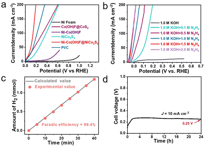
The anodic hydrazine oxidation performance of Ni–Co(OH)F@NiCo2S4 is further evaluated in a three-electrode system containing 1.0 M KOH and 0.1 M hydrazine (Fig. 4a). Compared to recently reported transition metal catalysts (Table S2†), Ni–Co(OH)F@NiCo2S4 nanorods require only 20 mV (vs. RHE) working potential to output 10 mA cm−2 current density. It is far lower than that required by Ni–Co(OH)F (446 mV), NiCo2S4 (101 mV), Co(OH)F@CoS2 (40 mV), Ni foam (940 mV), and even commercial Pt/C (33 mV). The excellent oxidation performance of Ni–Co(OH)F@NiCo2S4 may be related to the synergistic effect of core–shell interface engineering and Ni atom doping.39 To verify the current response to the hydrazine concentration, the LSV curves of Ni–Co(OH)F@NiCo2S4 nanorods in 1.0 M KOH electrolyte with different hydrazine concentrations were collected (Fig. 4b). Initially, without hydrazine, the Ni–Co(OH)F@NiCo2S4 nanorods show poor activity (353 mV at 10 mA cm−2) in 1.0 M KOH solution. In contrast, the anodic current sharply increases with the addition of 0.1 M hydrazine, showing a working potential of 20 mV (vs. RHE) at 10 mA cm−2. With an increase in the hydrazine concentration, the anodic current continuously increases, and it only requires an ultra-low working potential of −49 mV (vs. RHE) to output 10 mA cm−2 in 1.5 M hydrazine with 1.0 M KOH solution. And then, it shows no obvious improvement in HzOR performance with the increase in the hydrazine concentration to 2.0 M. In addition, the HzOR performances of different catalysts were further investigated at an optimal hydrazine concentration of 1.5 M (Fig. S10†). It is obvious that the Ni–Co(OH)F@NiCo2S4 core–shell nanorods have also demonstrated better performance than the other samples. The faradaic efficiency experiment was implemented for the sake of guaranteeing that hydrogen evolution is not impacted by the hydrazine molecule. The faradaic efficiency plot (Fig. 4c) reveals that the experimental hydrogen production amount is nearly identical to the theoretical value during test time. The high faradaic efficiency of 99.4% confirms that hydrazine would not intervene in the hydrogen evolution reaction. Additionally, the electrolysis cell stability is also investigated by using the Ni–Co(OH)F@NiCo2S4 couple as the anode and cathode. Evidently, the hydrazine-assisting hydrogen evolution system is able to steadily operate at 10 mA cm−2 without evident potential fluctuation (Fig. 4d). After 24 hours of testing, the cell voltage still remained at 0.25 V, which is far lower than the limitation cell voltage of water splitting (1.23 V).
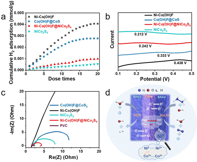
Furthermore, the H2 pulse chemical adsorption test (Fig. 5a) was performed and electrochemical hydrogen adsorption/desorption performance (Fig. 5b) was measured to gain deep insight into the hydrogen adsorption/desorption behaviors of catalysts. The results showed that as the number of pulses increased, the H2 adsorption capacities of catalysts reached saturation gradually. The final adsorption capacities of Ni–Co(OH)F, Co(OH)F@CoS2, Ni–Co(OH)F@NiCo2S4 and NiCo2S4 for H2 were 4.0, 2.7, 0.98 and 0.54 mmol mg−1, respectively.11 The corresponding electrochemical curves further indicated that Ni–Co(OH)F has the most positive hydrogen adsorption peak with 0.438 V compared to NiCo2S4 with 0.212 V, Ni–Co(OH)F@NiCo2S4 with 0.242 V and Co(OH)F@CoS2 with 0.333 V. As a more positive peak suggested the stronger adsorption for H species,40 it can be summarized that the order of hydrogen adsorption ability was Ni–Co(OH)F > Co(OH)F@CoS2 > Ni–Co(OH)F@NiCo2S4 > NiCo2S4, which agrees well with the H2 pulse chemical adsorption test results. In addition, the Ni0 species appeared in the XPS spectrum of Ni–Co(OH)F@NiCo2S4 core–shell nanorods possessing relatively weak adsorption for H species.33,40 This may adjust the strong H adsorption behavior of Co in the Ni–Co(OH)F@NiCo2S4 catalyst.8,12,42 Therefore, the Ni–Co(OH)F@NiCo2S4 core–shell nanorods show a moderate H adsorption behavior. Furthermore, moderate H adsorption capacity can promote the adsorption/desorption behaviors to achieve an effective balance, which is more beneficial to improve the generation of hydrogen.41,42 Taken together, the Ni–Co(OH)F@NiCo2S4 core–shell nanorods show the optimum hydrogen adsorption/desorption behaviors. The electrochemical impedance spectrum (EIS) was measured to study the charge transfer capability of catalysts.43 The results are in agreement with the expectation that Ni–Co(OH)F@NiCo2S4 will have the lowest charge transfer resistance (Fig. 5c). Combined with the reaction mechanism illustration (Fig. 5d), the excellent HER activity of Ni–Co(OH)F@NiCo2S4 could be attributed to the synergistic effect of core–shell interface engineering and Ni atom doping. This is consistent with the XPS results that the doping of Ni0 drives a partial electron transfer from Ni to Co, which promotes the conversion of Co3+ to Co2+.34 The low valence of Co2+ and Ni0 as well as the rapid electron transfer between the core and shell facilitates the efficient HER.23 Meanwhile Ni doping may lead to more drastic changes in the hydrogen adsorption/desorption behaviors of the surface layer of the NiCo2S4 shell, with the oxide core counteracting some of the Ni doping effect and allowing the hydrogen adsorption/desorption behaviors to converge to a more reasonable state.32,33
In summary, this study reports a novel core–shell heterostructure Ni–Co(OH)F@NiCo2S4 nanorod array electrode for hydrazine-assisted hydrogen evolution. The Ni–Co(OH)F@NiCo2S4 nanorods show excellent hydrogen evolution reaction (HER) activity with a low η10 of 97 mV and Tafel slope (58 mV dec−1). In addition, they also exhibit a low potential of −49 mV (vs. RHE) for the HzOR in 1.0 M KOH electrolyte with 1.5 M hydrazine. An ultralow cell voltage of 250 mV is required to achieve 10 mA cm−2 in a two-electrode system. The comprehensive analysis clearly demonstrated that the combination of core–shell interface engineering together with Ni doping synergistically promotes charge transfer and optimizes the hydrogen adsorption/desorption behaviors of Ni–Co(OH)F@NiCo2S4 nanorods, thus accelerating HER and HzOR kinetics. This work not only reports advanced Ni–Co(OH)F@NiCo2S4 nanorods for a hydrazine-assisted hydrogen evolution system, but also reveals great prospects for the combination of heteroatom doping and interface engineering in sustainable energy conversion technology.
Conflicts of interest
There are no conflicts of interest to declare.Acknowledgements
This work was supported by the National Key R&D Program of China (2018YFA0209401), National Natural Science Foundation of China (61705063 and 51974113), Natural Science Foundation of Heilongjiang Province (LH2022F051), Basic Scientific Research Fund of Provincial Universities of Heilongjiang (2021KYYWF1466), and Graduate Innovation Research Fund of Heilongjiang University of Science and Technology (YJSCX2022-211HKD).References
- C. Zhang, S. J. Liu, Z. Z. Mao, X. Liang and B. H. Chen, J. Mater. Chem. A, 2017, 5, 16646–16652 RSC.
- H. Y. Lu, W. Fan, Y. P. Huang and T. X. Liu, Nano Res., 2018, 11, 1274–1284 CrossRef CAS.
- X. Zhao, X. Y. Li, L. L. An, L. R. Zheng, J. L. Yang and D. L. Wang, Angew. Chem., Int. Ed., 2022, 61, e202206588 CAS.
- L. F. Fan, Y. X. Ji, G. X. Wang, J. X. Chen, K. Chen, X. Liu and Z. H. Wen, J. Am. Chem. Soc., 2022, 144, 7224–7235 CrossRef CAS PubMed.
- P. Wang, J. Qi, X. Chen, C. Li, W. P. Li, T. H. Wang and C. H. Liang, ACS Appl. Mater. Interfaces, 2020, 12, 4385–4395 CrossRef CAS PubMed.
- H. M. Sun, Z. H. Yan, F. M. Liu, W. C. Xu, F. Y. Cheng and J. Chen, Adv. Mater., 2020, 32, 1806326 CrossRef CAS PubMed.
- H. W. Huang, A. Cho, S. Kim, H. Jun, A. Lee, J. W. Han and J. Lee, Adv. Funct. Mater., 2020, 30, 2003889 CrossRef CAS.
- J. H. Song, C. Z. Zhu, B. Z. Xu, S. F. Fu, M. H. Engelhard, R. F. Ye, D. Du, S. P. Beckman and Y. H. Lin, Adv. Energy Mater., 2017, 7, 160155 Search PubMed.
- J. Y. Zhang, X. N. Tian, T. He, S. Zaman, M. Miao, Y. Yan, K. Qi, Z. H. Dong, H. F. Liu and B. Y. Xia, J. Mater. Chem. A, 2018, 6, 15653–15658 RSC.
- R. G. Kadam, T. Zhang, D. Zaoralová, M. Medved', A. Bakandritsos, O. Tomanec, M. Petr, J. Z. Chen, J. T. Miller, M. Otyepka, R. Zbořil, T. Asefa and M. B. Gawande, Small, 2021, 17, 2006477 CrossRef CAS PubMed.
- X. L. Tang, J. Y. Zhang, B. B. Mei, X. M. Zhang, Y. P. Liu, J. X. Wang and W. Li, Chem. Eng. J., 2021, 404, 126529 CrossRef CAS.
- J. Y. Zhang, H. M. Wang, Y. F. Tian, Y. Yan, Q. Xue, T. He, H. F. Liu, C. D. Wang, Y. Chen and B. Y. Xia, Angew. Chem., Int. Ed., 2018, 57, 7649–7653 CrossRef CAS PubMed.
- G. Feng, Y. Kuang, P. S. Li, N. N. Han, M. Sun, G. X. Zhang and X. M. Sun, Adv. Sci., 2017, 4, 1600179 CrossRef PubMed.
- I. Ledezma-Yanez, W. D. Z. Wallace, P. Sebastián-Pascual, V. Climent, J. M. Feliu and M. T. M. Koper, Nat. Energy, 2017, 2, 17031 CrossRef CAS.
- G. D. Liberto, L. A. Cipriano and G. Pacchioni, J. Am. Chem. Soc., 2021, 143, 20431–20441 CrossRef PubMed.
- D. Y. Wang, M. Gong, H. L. Chou, C. J. Pan, H. A. Chen, Y. P. Wu, M. C. Lin, M. Y. Guan, J. Yang, C. W. Chen, Y. L. Wang, B. J. Hwang, C. C. Chen and H. J. Dai, J. Am. Chem. Soc., 2015, 137, 1587–1592 CrossRef CAS PubMed.
- L. Yan, H. Y. Wang, J. L. Shen, J. Q. Ning, Y. J. Zhong and Y. Hu, Chem. Eng. J., 2021, 403, 126385 CrossRef CAS.
- K. L. Ao, Q. F. Wei and W. A. Daoud, ACS Appl. Mater. Interfaces, 2020, 12, 33595–33602 CrossRef CAS PubMed.
- L. L. Feng, M. H. Fan, Y. Y. Wu, Y. P. Liu, G. D. Li, H. Chen, W. Chen, D. J. Wang and X. X. Zou, J. Mater. Chem. A, 2016, 4, 6860–6867 RSC.
- J. Wang, T. Liao, Z. Z. Wei, J. T. Sun, J. J. Guo and Z. Q. Sun, Small Methods, 2021, 5, 2000988 CrossRef CAS PubMed.
- C. Wang, D. M. Liu, K. W. Zhang, H. Xu, R. Yu, X. M. Wang and Y. K. Du, ACS Appl. Mater. Interfaces, 2022, 14, 38669–38676 CrossRef CAS PubMed.
- Y. Y. Huang, R. Yang, G. Anandhababu, J. F. Xie, J. Q. Lv, X. T. Zhao, X. Y. Wang, M. X. Wu, Q. H. Li and Y. B. Wang, ACS Energy Lett., 2018, 3, 1854–1860 CrossRef CAS.
- X. Dong, Y. Q. Jiao, G. C. Yang, H. J. Yan, A. P. Wu, D. Z. Guo, Y. Wang, C. G. Tian and H. G. Fu, Sci. China Mater., 2021, 64, 1396–1407 CrossRef CAS.
- J. T. Ren, Y. S. Wang, Y. J. Song, L. Chen and Z. Y. Yuan, Appl. Catal., B, 2022, 309, 121279 CrossRef CAS.
- Z. X. Ge, T. J. Wang, Y. Ding, S. B. Yin, F. M. Li, P. Chen and Y. Chen, Adv. Energy Mater., 2022, 12, 2103916 CrossRef CAS.
- S. Adhikari, Y. Kwon and D. H. Kim, Chem. Eng. J., 2020, 402, 126192 CrossRef CAS.
- G. Q. Zhao, Y. Z. Jiang, S. X. Dou, W. P. Sun and H. G. Pan, Sci. Bull., 2021, 66, 85–96 CrossRef CAS.
- P. L. Zhai, Y. X. Zhang, Y. Z. Wu, J. F. Gao, B. Zhang, S. Y. Cao, Y. T. Zhang, Z. W. Li, L. C. Sun and J. G. Hou, Nat. Commun., 2020, 11, 5462 CrossRef CAS PubMed.
- H. Wu, Q. Lu, J. F. Zhang, J. J. Wang, X. P. Han, N. Q. Zhao, W. B. Hu, J. J. Li, Y. N. Chen and Y. D. Deng, Nano-Micro Lett., 2020, 12, 162 CrossRef CAS PubMed.
- Y. F. Tian, X. Y. Xue, Y. Gu, Z. X. Yang, G. Hong and C. D. Wang, Nanoscale, 2020, 12, 23123 Search PubMed.
- K. Chakrapani, G. Bendt, H. Hajiyani, T. Lunkenbein, M. T. Greiner, L. Masliuk, S. Salamon, J. Landers, R. Schlögl, H. Wende, R. Pentcheva, S. Schulz and M. Behrens, ACS Catal., 2018, 8, 1259–1267 CrossRef CAS.
- S. H. Chae, A. Muthurasu, T. Kim, J. S. Kim, M. S. Khil, M. Lee, H. Kim, J. Y. Lee and H. Y. Kim, Appl. Catal., B, 2021, 293, 120209 CrossRef CAS.
- J. Y. Zhang, T. He, M. D. Wang, R. J. Qi, Y. Yan, Z. H. Dong, H. F. Liu, H. M. Wang and B. Y. Xia, Nano Energy, 2019, 60, 894–902 CrossRef CAS.
- Y. Wang, Y. Q. Jiao, H. J. Yan, G. C. Yang, C. G. Tian, A. P. Wu, Y. Liu and H. G. Fu, Angew. Chem., Int. Ed., 2022, 61, e202116233 CAS.
- J. Y. Zhang, Y. Yan, B. B. Mei, R. J. Qi, T. He, Z. T. Wang, W. S. Fang, S. Zaman, Y. Q. Su, S. J. Ding and B. Y. Xia, Energy Environ. Sci., 2021, 14, 365–373 RSC.
- F. F. Yuan, J. D. Wei, G. X. Qin and Y. H. Ni, J. Alloys Compd., 2020, 830, 154658 CrossRef CAS.
- Y. X. Wei, Y. L. Lv, B. D. Guo and J. R. Gong, J. Energy Chem., 2021, 57, 587–592 CrossRef CAS.
- Z. X. Wu, D. Z. Nie, M. Song, T. T. Jiao, G. T. Fu and X. E. Liu, Nanoscale, 2019, 11, 7506–7512 RSC.
- L. C. Zhang, J. Liang, L. C. Yue, K. Dong, J. Li, D. L. Zhao, Z. R. Li, S. J. Sun, Y. S. Luo, Q. Liu, G. W. Cui, A. A. Alshehri, X. D. Guo and X. P. Sun, Nano Res. Energy, 2022, 1, e9120028 CrossRef.
- J. Y. Zhang, J. Y. Liang, B. B. Mei, K. Lan, L. H. Zu, T. C. Zhao, Y. Z. Ma, Y. Chen, Z. R. Lv, Y. Yang, C. H. Yu, Z. Xu, B. Y. Xia, W. Li, Q. H. Yuan and D. Y. Zhao, Adv. Energy Mater., 2022, 12, 2200001 CrossRef CAS.
- R. Zhang, X. X. Wang, S. J. Yu, T. Wen, X. W. Zhu, F. X. Yang, X. N. Sun, X. K. Wang and W. P. Hu, Adv. Mater., 2017, 29, 1605502 CrossRef PubMed.
- Y. Liu, J. H. Zhang, Y. P. Li, Q. Z. Qian, Z. Y. Li, Y. Zhu and G. Q. Zhang, Nat. Commun., 2020, 11, 1853 CrossRef CAS PubMed.
- M. Song, Z. J. Zhang, Q. W. Li, W. Jin, Z. X. Wi, G. T. Fu and X. E. Liu, J. Mater. Chem. A, 2019, 7, 3697 RSC.
Footnotes |
| † Electronic supplementary information (ESI) available: Experimental details and SEM, XRD, XPS and other electrochemical measurements. See DOI: https://doi.org/10.1039/d2se01414a |
| ‡ These authors made equal contribution to this work. |
| This journal is © The Royal Society of Chemistry 2023 |

