
 Open Access Article
 This Open Access Article is licensed under a
 Creative Commons Attribution 3.0 Unported Licence
Optimizing copper nanoparticles with a carbon shell for enhanced electrochemical CO2 reduction to ethanol†
Ting
Yao
a,
Wei
Xia
 *a,
Shitao
Han
a,
Shuaiqiang
Jia
a,
Xue
Dong
a,
Min
Wang
a,
Jiapeng
Jiao
a,
Dawei
Zhou
a,
Jiahao
Yang
a,
Xueqing
Xing
d,
Chunjun
Chen
a,
Mingyuan
He
ac,
Haihong
Wu
*ab and
Buxing
Han
*abc
*a,
Shitao
Han
a,
Shuaiqiang
Jia
a,
Xue
Dong
a,
Min
Wang
a,
Jiapeng
Jiao
a,
Dawei
Zhou
a,
Jiahao
Yang
a,
Xueqing
Xing
d,
Chunjun
Chen
a,
Mingyuan
He
ac,
Haihong
Wu
*ab and
Buxing
Han
*abc
aShanghai Key Laboratory of Green Chemistry and Chemical Processes, School of Chemistry and Molecular Engineering, East China Normal University, Shanghai 200062, China. E-mail: wxia@chem.ecnu.edu.cn; hhwu@chem.ecnu.edu.cn; hanbx@iccas.ac.cn
bInstitute of Eco-Chongming, 20 Cuiniao Road, Chenjia Town, Chongming District, Shanghai 202162, China. E-mail: hhwu@chem.ecnu.edu.cn
cBeijing National Laboratory for Molecular Sciences, CAS Key Laboratory of Colloid and Interface and Thermodynamics, CAS Research/Education Center for Excellence in Molecular Sciences, Institute of Chemistry, Chinese Academy of Sciences, Beijing 100190, China. E-mail: hanbx@iccas.ac.cn
dBeijing Synchrotron Radiation Facility, Institute of High Energy Physics, Chinese Academy of Sciences, Beijing Municipality 100049, China
First published on 24th November 2023
Abstract
The electrochemical reduction of carbon dioxide (CO2RR) holds great promise for sustainable energy utilization and combating global warming. However, progress has been impeded by challenges in developing stable electrocatalysts that can steer the reaction toward specific products. This study proposes a carbon shell coating protection strategy by an efficient and straightforward approach to prevent electrocatalyst reconstruction during the CO2RR. Utilizing a copper-based metal–organic framework as the precursor for the carbon shell, we synthesized carbon shell-coated electrocatalysts, denoted as Cu-x-y, through calcination in an N2 atmosphere (where x and y represent different calcination temperatures and atmospheres: N2, H2, and NH3). It was found that the faradaic efficiency of ethanol over the catalysts with a carbon shell could reach ∼67.8%. In addition, the catalyst could be stably used for more than 16 h, surpassing the performance of Cu-600-H2 and Cu-600-NH3. Control experiments and theoretical calculations revealed that the carbon shell and Cu–C bonds played a pivotal role in stabilizing the catalyst, tuning the electron environment around Cu atoms, and promoting the formation and coupling process of CO*, ultimately favoring the reaction pathway leading to ethanol formation. This carbon shell coating strategy is valuable for developing highly efficient and selective electrocatalysts for the CO2RR.
Introduction
Electrocatalytic carbon dioxide reduction (CO2RR), powered by clean and renewable energy resources, is a widely explored reaction due to its promise as a sustainable approach to mitigating global warming and promoting sustainable energy utilization.1–3 Among the various CO2RR products, the production of high-value multicarbon (C2+) compounds has garnered significant attention from researchers. However, most of these technologies still require better catalysts to support electrochemical reactions. In particular, there is a lack of in-depth understanding of a catalyst's dynamic structure under reaction conditions, which is however critically needed to inform rational catalyst design.4–6Copper (Cu) has been extensively studied in the CO2RR due to its ability to induce CO* dimerization (where * represents the adsorption state), especially towards deep-reduction products (e.g., eight-electron transfer for methane (CH4) and twelve-electron transfer for ethylene (C2H4) and ethanol (C2H5OH)).7–9 Various methods, such as modifications of the microstructure,10,11 hydrophobicity,12 defects,13 facets,14–16 and heteroatom doping,17,18 have been applied to enhance C2+ product selectivity and catalytic activity. However, there is also increasing evidence that significant catalyst restructuring can already occur as soon as the Cu-based catalysts are placed into an electrolyte, and these changes impact the subsequent catalyst activity and selectivity during the reaction.47 Despite the increasing utilization of heteroatom-induced modification of copper catalysts as an electrode preparation method to enhance catalyst stability, there have been limited investigations into the detailed analysis of morphological transformations and the exploration of strategies for controlled synthesis of the most advantageous nanostructures for a specific electrocatalytic process.
Carbon shells serve as effective physical barriers between nanocatalysts to address catalyst restructuring, reducing particle aggregation, and preventing oxidation. In the past decade, carbon-shell-encapsulated nanoparticles have shown great potential as electrocatalysts for electrochemical energy applications. For example, in the Pt–aniline complex, carbon shells are simply encapsulated on Pt nanoparticles to enhance the long-term stability of proton exchange membrane fuel cells,19 and carbon-encapsulated ordered PtFe nanoparticles exhibit exceptional activity and durability as electrocatalysts for fuel cell applications.20 Additionally, several studies have indicated that the interface hybridization between carbon matrices and transition metals significantly influences the activity and selectivity of electrocatalysts.20 This is attributed to the modulation of the electronic structure of the external carbon shell by the core metal particles, which leads to significant changes in the electron density of the carbon shells.21,22
In this study, we present a novel carbon shell (C shell) coating protection strategy, employing an efficient and straightforward approach, aimed at preventing electrocatalyst reconstruction during the CO2RR. A copper-based metal–organic framework (Cu-MOF) was selected as the precursor for the C shell, and the carbon shell was realized through calcination in an N2 atmosphere. Furthermore, Cu-MOFs were also exposed to different gas atmospheres, such as H2 and NH3, at various temperatures to demonstrate the significance of the C shell. The resulting catalysts were labeled as Cu-x-y, where x and y represent the calcination temperature and atmosphere, respectively. It was found that Cu-600-N2 consisted of Cu nanoparticles with a 2 nm thick carbon shell and Cu–C bonds, and it showed excellent stability and efficiency for the CO2-to-ethanol reaction. The faradaic efficiency (FE) of ethanol could be as high as 67.8%, much better than that of Cu-600-H2 and Cu-600-NH3. The carbon shell and Cu–C bonds played a crucial role in stabilizing the catalyst, tuning the electron environment around Cu atoms, promoting the formation of CO*, and following C–C coupling to generate ethanol.
Results and discussion
Synthesis and characterization of C shell-protected Cu
First, Cu-MOFs were synthesized using a solvothermal approach based on a bottom-up procedure, which followed a previously reported procedure with certain modifications.48,49 Terephthalic acid (H2BDC), 1,4-diazabicyclooctane (DABCO), and copper nitrate Cu(NO3)2 were utilized for the synthesis of the Cu-MOFs, as illustrated in Fig. 1a. Each Cu2+ cation in the Cu-MOFs is coordinated with four oxygen atoms from H2BDC and one nitrogen atom from DABCO molecules within a single building unit. The resulting Cu-MOFs had a size of approximately 2 μm (Fig. S1†), and nitrogen adsorption experiments reveal a Brunauer–Emmett–Teller (BET) surface area of 223.5967 m2 g−1 (Fig. S2†). The X-ray diffraction (XRD) pattern displayed a well-crystallized structure of Cu-MOFs, consistent with the previous results (Fig. S3†).48,49 To produce the Cu-x-N2 catalysts, the precursor Cu-MOFs were pyrolyzed at various temperatures (400, 500, 600, 700, 800 and 900 °C) in an N2 environment. Using the same approach, reference compounds Cu-x-H2 and Cu-x-NH3 were also produced under H2 and NH3 atmospheres, respectively. As shown in Fig. S4a,† the XRD patterns of all three catalysts Cu-600-N2, Cu-600-H2, and Cu-600-NH3 displayed three distinct diffraction peaks at approximately 43.3°, 50.5°, and 74.1°, which correspond to Cu (111), Cu (200), and Cu (220) faces of metallic Cu (JCPDS no. 04-0836), respectively. The results of inductively coupled plasma (ICP) analysis are presented in Table S1,† which indicates that there was hardly any difference in copper loading between the three catalysts.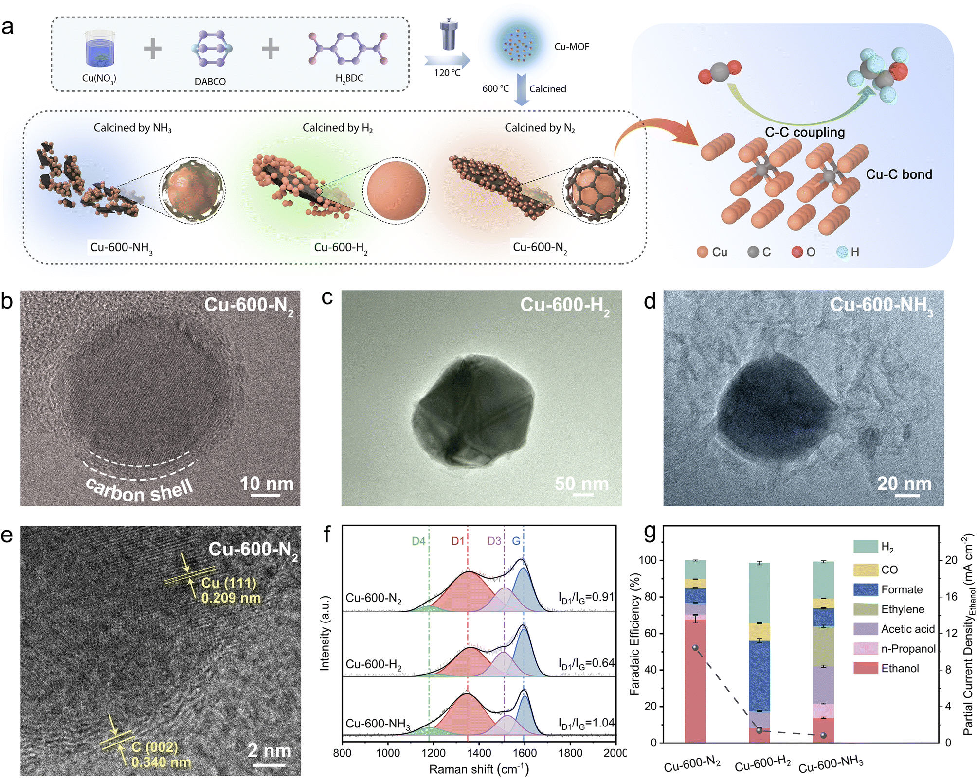 | ||
| Fig. 1 (a) The schematic illustration of the preparation of catalysts. TEM characterization of (b) Cu-600-N2 (c) Cu-600-H2, and (d) Cu-600-NH3, respectively. (e) HR-TEM images of Cu-600-N2. (f) Raman spectra and (g) FE over Cu-600-N2, Cu-600-H2, and Cu-600-NH3 in CO2-saturated 0.1 M KHCO3 aqueous solutions using an H-cell at −0.8 V (vs. RHE). | ||
The TEM and SEM images showed that Cu2+ was converted into monodispersed copper nanospheres with a polycrystalline structure after heat treatment (Fig. 1b–d and S4b–d†). The morphology of the three catalysts calcined in different atmospheres differed significantly. First, as can be seen from Fig. 1b–d and S4b–d,† Cu-600-N2, and Cu-600-NH3 were composed of nanoparticles with an average size of less than 100 nm, while Cu-600-H2 was composed of larger-sized sintered particles (Fig. S5–S7†). TEM characterization (Fig. S5†) indicates that the particle size of Cu nanoparticles (Cu NPs) deposited on carbon ranged from 20 to 50 nm in the Cu-600-N2 catalyst. In addition, the combination of carbon and Cu-NPs depended on atmospheric conditions in the calcination process. As shown in Fig. 1b and e, the interplanar spacings of the carbon layers and the Cu NPs were 0.34 nm and 0.210 nm, respectively, consistent with the C (002) and Cu (111) crystal planes.20–22 The Cu NPs, covered with an about 3 nm-thick carbon shell, were seamlessly incorporated into the C framework in Cu-600-N2. Previous research has demonstrated that thin carbon shells possess permeability for small molecules and do not impede the mass transport of reactants.23–25 The elemental mapping also indicated the tight binding of Cu and carbon in Cu-600-N2 (Fig. S9–S11†). In contrast, due to the reducibility of H2, the carbon is squeezed out of the Cu-MOF precursor, resulting in the apparent separation of carbon and Cu-NPs in Cu-600-H2 (Fig. 1c). Additionally, in Cu-600-NH3 (Fig. 1d), NH3 inhibited the sintering of carbon particles, resulting in an incomplete and fragmented carbon layer.26
Raman spectroscopy was used to determine the reason for the discrepancy. As shown in Fig. 1f, the two broad peaks at 1348.2 and 1596.1 cm−1 correspond to the D and G bands, respectively. The D band refers to sp2 hybridized carbon and material defects, while the G band is related to an ideal graphitic lattice. Therefore, the intensity ratio between the D and G bands (ID/IG) can be used to determine the degree of graphitization of carbon materials.23,24 The smaller the ratio is, the higher the degree of graphitization. By comparing the intensity ratios of several Raman bands, we found that the ID/IG ratios increased from Cu-600-H2 (0.64) to Cu-600-N2 (0.91) and Cu-600-NH3 (1.04). This suggests that Cu-600-NH3 had a more disordered carbon support, and Cu-600-H2 had the most significant graphitization degree. Thus, different atmospheres resulted in various states of carbon layers, with ordered organization resulting in carbon separation, and disordered carbon may result in diminished conductivity and confinement ability.
The specific surface area and the pore-size distribution of the catalysts are further investigated using the N2adsorption–desorption isotherm at 77 K which is shown in Fig. S12a.† The isotherms are classified as the type IV category, displaying an H3 hysteresis loop, which indicates a mesoporous structure.50 The pore size distribution estimated by the nonlocal density functional theory method shows that the primary pore sizes are 4–6 nm for Cu-600-N2, 1.5 nm for Cu-600-NH3, and 1.6 nm for Cu-600-H2 (Fig. S12b†). Furthermore, mesoporous Cu-600-N2 exhibits a notably high BET surface area of 1004.63 m2 g−1 and a sufficient pore volume of 2.96 cm3 g−1 (Table S2†). This extensive surface area offers a greater number of active sites and reactant transmission channels. To further evaluate the adsorption strength of CO2 on the catalyst surface, CO2 temperature-programmed desorption (CO2 TPD) has been conducted under identical mass loading conditions (Fig. S13a†). The results indicate that the desorption temperature and peak intensity of chemically adsorbed CO2 on Cu-600-N2 are higher than those of Cu-600-H2 and Cu-600-NH3, indicating stronger adsorption capability of Cu-600-N2 for CO2.51 Furthermore, the result of CO2 adsorption isotherms in Fig. S13b† is corroborated with the CO2 TPD analyses.
Control experiments were conducted to investigate the initial impact of different carbon layer states on the CO2RR, and the results are presented in Fig. 1g. Compared to samples Cu-600-H2 and Cu-600-NH3, Cu-600-N2 consisting of Cu nanoparticles encapsulated in a thin and complete carbon shell, exhibited significantly enhanced ethanol selectivity. This improvement is possibly attributed to the synergistic effect between Cu nanoparticles and the carbon shell in Cu-600-N2, and a detailed analysis will be provided below.
Structural characterization
To investigate the impact of various calcination atmospheres on the performance of the catalysts, a series of Cu-based catalysts pyrolyzed under different atmospheres were characterized as follows. First, it is evident from the results discussed above that different atmospheres resulted in varying degrees of graphitization, with the degree of graphitization being Cu-600-H2 > Cu-600-N2 > Cu-600-NH3. In the high-resolution Cu 2p X-ray photoelectron spectra (XPS) (Fig. 2a), the peaks with a binding energy (BE) of around 952.2 and 932.3 eV are assigned to Cu(I)/Cu(0) species, whereas the peaks at 954.3 and 934.5 eV should be attributed to Cu(II).25,26 Cu-600-N2 and Cu-600-NH3 exhibited shifted metallic Cu(0) peaks compared with Cu-600-H2, indicating a higher valence state of Cu in the former. This also signifies that the interfacial charge may be transferred from Cu nanoparticles to the carbon support.27,28 Based on the relative intensities of the C 1s peaks in Fig. 2b, the C 1s XPS spectrum was fitted with six peaks. The deconvoluted C 1s peaks at 283.2, 284.6, 285.5, 286.8, and 288.5 correspond to Cu–C, sp2–C, sp3–C, C–O, and C![[double bond, length as m-dash]](https://www.rsc.org/images/entities/char_e001.gif) O groups,29–31 respectively. Notably, the defective sp3 carbon atoms were introduced into Cu-600-NH3. This coincides with the Raman and SEM results that Cu-600-NH3 had the least graphitized carbon support. The percentage of sp2 and sp3-hybridized C atoms was estimated as shown in Table S3.† Moreover, due to charge transfer at the interface, a typical “shoulder” appears at the low binding energy of C 1s. A spilled peak at 283.2 in Cu-600-N2 and Cu-600-NH3 indicates a strong interaction between metal and carbide (M–C bond).29 Additionally, the Cu–C levels caused by N2 are about one-fold larger than those induced by NH3. Our research revealed that the nitrogen environment might create a certain content of carbon defects and enhance the synergy between the M–C bonds. The effect of other gases on the properties of the catalysts was also investigated. NH3 hindered the sintering of carbon particles, resulting in the carbon support with poor graphitization and electroconductivity. On the other hand, in an H2 environment, Cu-MOF precursors tend to produce a high degree of graphitization.26,27
O groups,29–31 respectively. Notably, the defective sp3 carbon atoms were introduced into Cu-600-NH3. This coincides with the Raman and SEM results that Cu-600-NH3 had the least graphitized carbon support. The percentage of sp2 and sp3-hybridized C atoms was estimated as shown in Table S3.† Moreover, due to charge transfer at the interface, a typical “shoulder” appears at the low binding energy of C 1s. A spilled peak at 283.2 in Cu-600-N2 and Cu-600-NH3 indicates a strong interaction between metal and carbide (M–C bond).29 Additionally, the Cu–C levels caused by N2 are about one-fold larger than those induced by NH3. Our research revealed that the nitrogen environment might create a certain content of carbon defects and enhance the synergy between the M–C bonds. The effect of other gases on the properties of the catalysts was also investigated. NH3 hindered the sintering of carbon particles, resulting in the carbon support with poor graphitization and electroconductivity. On the other hand, in an H2 environment, Cu-MOF precursors tend to produce a high degree of graphitization.26,27
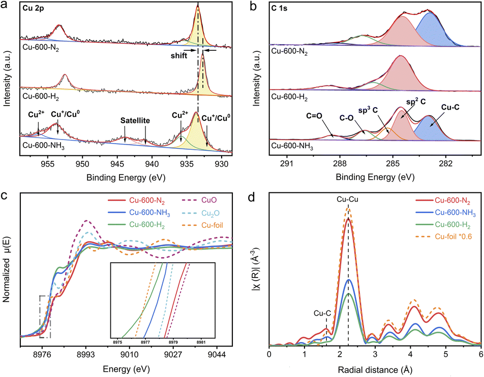 | ||
| Fig. 2 (a) High-resolution Cu 2p XPS spectra and (b) C 1s XPS spectra of Cu-600-NH3, Cu-600-N2, and Cu-600-H2. (c) Normalized Cu K-edge XANES spectra and (d) Cu K-edge FT-EXAFS spectra in the R-space of Cu-600-NH3, Cu-600-N2, Cu-600-H2, Cu foil, CuO, and Cu2O. | ||
To further examine the electronic structures and chemical configurations of catalysts Cu-600-N2, Cu-600-H2 and Cu-600-NH3, X-ray absorption near-edge structure (XANES) and extended X-ray absorption fine structure (EXAFS) spectroscopies were performed. Fig. 2c shows the Cu K-edge XANES spectra of Cu-600-N2, Cu-600-H2 and Cu-600-NH3, alongside CuO, Cu2O, and Cu foil references. Compared to Cu-600-H2 and Cu-600-NH3, the absorption edge position of Cu-600-N2 is positively shifted and virtually identical to that of CuO, suggesting a higher oxidation state of the copper species and a tendency toward a +2 valence state. This is consistent with the XPS results. In addition, the edge positions of the spectra acquired on Cu-600-H2 and Cu-600-NH3 are between Cu2O and Cu, suggesting that the oxidation state of the copper species is between valence states +1 and +2 in these samples, as indicated by the previous XPS results. Due to the reducibility of hydrogen, the valence state of Cu-600-H2 is more inclined toward Cu0, while the valence state of Cu-600-NH3 is almost +0.5 on average. The Fourier-transformed (FT) k3-weighted EXAFS oscillation in Fig. 2d and S15† showed that the three catalysts all demonstrate characteristic peaks similar to those of the Cu foil, with a prominent peak at a distance of approximately 2.1, corresponding to the Cu–Cu coordination in R space. Furthermore, scattering was detected at a distance of 1.5 Å, which corresponds to the first coordination shell of Cu–C in Cu-600-N2. This observation was further confirmed by the appearance of the Cu–C peak at 283.2 eV in the C 1s XPS spectrum, providing additional evidence for the coordination environment of the Cu–C bond in Cu-600-N2.
CO2RR activity investigation
The CO2RR catalytic performances of Cu-600-N2, Cu-600-H2 and Cu-600-NH3 were evaluated in an H-type cell with a CO2-saturated 0.1 M KHCO3 electrolyte. Fig. 3a shows the linear sweep voltammetry (LSV) curves for different catalysts in CO2- and Ar-saturated 0.1 M KHCO3 electrolytes. The notably higher current density observed in a CO2-saturated electrolyte in comparison to an Ar-saturated electrolyte indicates the reduction of CO2. In contrast, the current in the Ar-saturated electrolyte predominantly originates from the hydrogen evolution reaction (HER). Notably, Cu-600-N2 exhibits a significantly higher current density, indicating that Cu-600-N2 is more conducive to the CO2RR rather than the HER.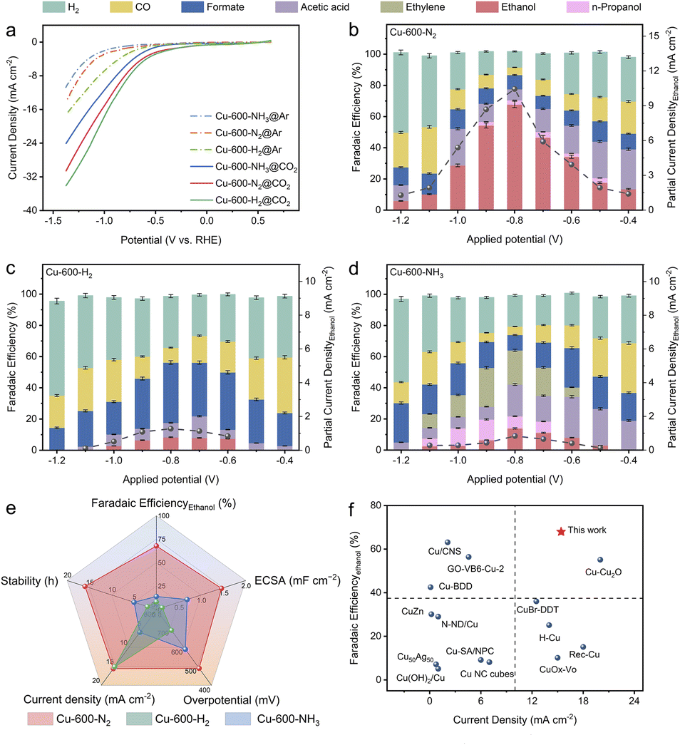 | ||
| Fig. 3 (a) LSV curves in CO2- and Ar-saturated 0.1 M KHCO3 aqueous solutions for Cu-600-N2, Cu-600-H2, and Cu-600-NH3. FE and partial current density for (b) Cu-600-N2, (c) Cu-600-H2, and (d) Cu-600-NH3 in CO2-saturated 0.1 M KHCO3 aqueous solutions at different potentials (vs. RHE), and error bars are given by the shaded areas. The error bar indicates the standard deviation of three independent measurements. (e) Comparison of the overall performance of the three catalysts, Cu-600-N2, Cu-600-H2, and Cu-600-NH3. (f) Comparison of stability with other recently reported advanced CO2RR Cu-based electrocatalysts in an H-type cell. | ||
At a low current density, Cu-600-N2 with a graphitic C shell produced a substantial amount of CO and acetic acid (Fig. 3b), while a small amount of ethanol was generated, indicating that C–C coupling of Cu-600-N2 was initiated at a lower overpotential. As the applied potential became more negative, the selectivity of CO and acetic acid decreased while the FE of ethanol increased, exhibiting a volcano-like trend. Notably, the conversion of CO2 to ethanol exhibited the highest FE of 67.8% at −0.8 V, much higher than that of Cu-600-H2, Cu-600-NH3, and other previously reported Cu-based catalysts for converting CO2 to ethanol.32–34 According to previous reports, high selectivity for ethanol suggests a greater amount of surface-bound CO* or CHO*, which is a crucial step in forming C2 products.35 The number of other hydrocarbons produced was minor compared to that of ethanol; small amounts of n-propanol, acetic acid, and formate were generated with FE values of 2.8%, 7.8%, and 9.3%, respectively. The 1H NMR spectra of the products after the CO2RR are shown in Fig. S17.† However, the HER gradually became dominant at more negative potentials. Isotope-labelled 13CO2 was used as feed gas to trace the carbon source in ethanol production. The 1H-NMR analysis also confirmed that ethanol was produced from the CO2RR and not due to contaminants52 (Fig. S18†).
The FEs for Cu-600-H2 and Cu-600-NH3 were also determined for comparison (Fig. 3c and d). At 0.8 V vs. RHE, formate was the predominant product (38.6%) for Cu-600-H2, with an ethanol FE of 10.3%. Because severe Cu reconstruction hindered the realization of the synergy effect, it was difficult to enhance the ethanol product selectivity due to favorable HER. For the Cu-600-NH3 electrode, the FE of ethanol was only 15.2% at −0.8 V vs. RHE. When the proportion of amorphous carbon was high, the selectivity of ethanol was poor, and the hydrocarbon products were a complex mixture (C2H4: 24.9%; n-propanol: 8.1%; acetic acid: 20.4%; and formate: 9.9%). At the same potential, the partial current density of Cu-600-N2 was substantially greater than that of Cu-600-H2 and Cu-600-NH3. It should be noted that the onset potential for C2H5OH formation on Cu-600-N2 was approximately −400 mV (vs. RHE), corresponding to an overpotential of ∼490 mV, which was lower than the overpotentials observed for Cu-600-H2 (∼690 mV) and Cu-600-NH3 (∼590 mV) for the reduction of CO2 to C2H5OH (Fig. 3e). These results directly demonstrate the significance of developing an appropriate graphitization degree system to prevent reconstruction of Cu and promote high selectivity for ethanol production.
In addition, temperature is also a crucial factor influencing the graphitization degree of carbon materials. Therefore, a series of Cu-x-N2 catalysts were prepared by altering the Cu-MOF annealing temperature (x = 400, 500, 600, 700, 800 and 900 °C). At lower temperatures of 400 or 500 °C (Fig. S19a and b†), Cu NPs are fully encapsulated in a thicker carbon shell, indicating that the bulk MOF has not been effectively delaminated. Increasing the calcination temperature is beneficial for decomposing the metal–organic framework. At 600 °C (Fig. S19c†), the Cu-MOF structure is almost entirely delaminated into layered structures, with partial removal of Cu NPs from the graphene shell, resulting in the formation of a porous structure and graphene nanocages (inset of Fig. S19c†). During the calcination process, Ostwald ripening occurs, and metal nanoparticles tend to reduce the total surface energy by aggregating and forming larger particles, thereby reducing the interfacial surface energy between the particles. Therefore, as the temperature further increases from 700 °C to 900 °C (Fig. S19d–f†), Cu NPs melt and migrate, aggregating into larger particles. Additionally, with the increase of temperature, the metal particles break through the constraints of the carbon shell, resulting in even larger aggregation sizes. Indeed, larger metal particles can lead to a reduced electrochemical active surface area and an increase in electron transfer resistance, ultimately resulting in a decrease in catalytic reaction activity. As shown in Fig. S20,† the FE of ethanol follows a volcano pattern as the applied temperature was increased, reaching a maximum of 67.8% at 600 °C, and the current reached 15.4 mA cm−2. The catalyst performance of the other two catalysts, Cu-x-H2 and Cu-x-NH3, is also shown in Fig. S21 and S22.†
To explore the origins of enhanced CO2RR by different carbon shell structures, the influence of various catalysts on the active sites and charge transfer kinetics is examined. The electrochemical active surface area (ECSA) of the catalysts was estimated by measuring the electrochemical double-layer capacitance (Cdl) obtained from the CV curves at different scan rates.36 As shown in Fig. S23,† Cu-600-N2 can provide the largest ECSA, which facilitates an improved contact interface with the electrolyte and exposes more active sites to enhance the adsorption of various intermediates. The electrochemical impedance spectroscopy (EIS) depicted in Fig. S24† revealed that Cu-600-N2 exhibits a smaller semicircular radius and charge transfer resistance in the Nyquist plot, indicating a faster charge transfer process occurring on Cu-600-N2 compared to Cu-600-H2 and Cu-600-NH3. It expedites the transfer of electrons to CO2 to stabilize the reduced CO2˙ intermediate, which is essential for the electroreduction of CO2.37,38 Due to poor graphitization, the Cu-600-NH3 electrode features the most significant charge transfer resistance and the worst conductivity.27 This phenomenon demonstrates that a suitable degree of graphitization and a high Cu–C combination is advantageous for the CO2RR and that these two parameters may act synergistically to enhance the activity and selectivity of the CO2RR.
The stability of catalysts for the CO2RR is of utmost importance for their practical application. As shown in Fig. 4a, Cu-600-N2 remained stable and had excellent catalytic activity over 16 hours at an applied potential of −0.8 V, which is more stable than the other catalysts. SEM revealed that the C shell-coated Cu nanoparticles maintained their embedded morphology and chemical state even after long reaction times (Fig. 4b and S25†). Cu wrapped by a protective shell exhibited significantly improved stability due to the prevention of Cu particle aggregation. For unprotected Cu nanoparticles or disordered carbon, however, the surface changed significantly after a few hours at a high reaction rate (Fig. S26–S28†). The Cu nanoparticles on the surface underwent severe surface reconstruction and agglomerated into many micron-sized and rough aggregates, and the ethanol selectivity also decreased rapidly. Furthermore, as depicted in Fig. S29,† the anti-corrosion properties of Cu-600-N2, Cu-600-H2, and Cu-600-NH3 were evaluated by Tafel analysis. Cu-600-N2 exhibited the best corrosion resistance among the three catalysts due to its more positive corrosion potential than Cu-600-H2 and Cu-600-NH3.
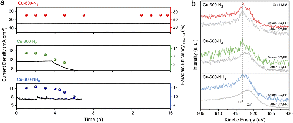 | ||
| Fig. 4 (a) CO2 electroreduction stability of Cu-600-N2, Cu-600-H2, and Cu-600-NH3 at a potential of −0.8 V (vs. RHE) in 0.1 M KHCO3. (b) XPS Cu LMM spectra of Cu-600-N2, Cu-600-H2, and Cu-600-NH3 before and after the CO2RR. The CO2RR was conducted at a potential of −0.8 V (vs. RHE) for 3 hours. | ||
The above performance comparison demonstrates that Cu-600-N2 exhibited superior performance to Cu-600-H2 and Cu-600-NH3 in multiple aspects (as depicted in Fig. 3e). The outstanding stability of Cu-600-N2 could be attributed to the protective effect of the carbon layer encapsulating the Cu nanoparticles. The internal Cu nanoparticles could also collaborate with the surface carbon shell to form stable Cu–C bonds, promoting the catalytic reaction and producing a synergy effect.39–41 This synergistic effect enabled Cu-600-N2 to maintain high FE and current density during continuous electrocatalysis, making it comparable to recently reported Cu-based electrocatalysts for CO2-to-ethanol conversion in an H-cell setup (as shown in Fig. 3f and Table S4†).
Mechanistic study on enhanced C–C coupling
The experiment confirmed that the carbon coating of the Cu nanoparticles played a significant role in ethanol generation. To gain more fundamental insights, DFT calculations were also performed to verify the effect of the Cu–C bond on the performance of the CO2RR to ethanol. The Cu–C bond structure model was constructed by doping C on the subsurface of Cu, while bare Cu was used for comparison. The doping sites of C and the adsorbed sites are based on the most energetically stable structures. Fig. 5a illustrates the schematic diagrams for CO2RR pathways that achieve CO* and CO* dimerization on Cu–C. For bare Cu surfaces, the schematic diagrams of the reaction pathway are illustrated in Fig. S30.† Initially, one CO2 molecule forms a *CO species on the copper surface through protonation, and then *CHO is formed by one proton transfer process. Subsequently, *CHO undergoes coupling with another CO* by *CHO + CO* → *CHO–CO,42,43 which is considered the rate-determining step in the ethanol formation path. The free energy profiles (Fig. 5b) suggest that Cu–C exhibits a low reaction energy barrier (0.02 eV) in the process of CO* formation, significantly lower than that on bare Cu (0.21 eV). Therefore, the Cu–C surface is favorable for the formation of CO*, which can improve the coverage of CO*. It has been reported that the energy barrier for CO dimerization can be lowered by increasing the coverage of CO*, which can improve its dimerization.44,45 When CO is further hydrogenated to generate CHO, the energy barrier is as low as 0.12 eV on the Cu–C surface, which reduces the overall reaction energy barrier for subsequent C–C coupling. In addition, the uphill energy for CHO formation on bare Cu is 0.52 eV, which is much higher than that on Cu–C (0.4 eV). The large free energy implies high-energy barriers for the CO2-to-C2 process. Therefore, the Cu–C bond can promote the CO2RR to form CO* and OCCHO* and reduce the energy barrier for CO* dimerization, which leads to higher selectivity for ethanol.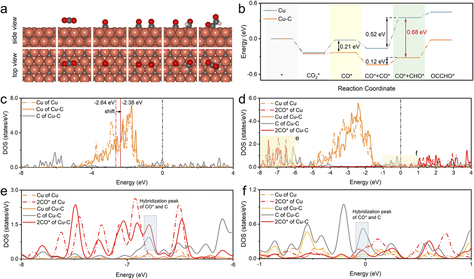 | ||
| Fig. 5 (a) The proposed dimerization mechanism for ethanol formation involves optimized structures of adsorbed species on the Cu–C surface, shown in the top and side views. Cu: orange, C: gray, O: red, H: white. (b) Free energy diagram for CO dimerization on the pristine Cu–C and bare Cu surface. (c) The calculated d-PDOS of surface Cu and C atoms on Cu–C and bare Cu planes. The two blue lines indicate the d-band center positions with the calculated values. (d) The d-PDOS of surface Cu, C, and CO* on Cu–C and bare Cu planes after adsorption of the two intermediate CO*, and (e) and (f) are the enlarged local views. | ||
In addition, the charge density difference (CDD) of Cu–C was calculated to study the space charge distribution and influence on the valence state of the Cu and electric properties of the catalyst. Fig. S31–S33† shows that based on DFT calculations, Cu–C exhibits charge transfer from Cu to carbon due to the strong electronic attraction properties of the graphic structure; this was consistent with the XPS fitting results in the experiment. The plots of the d-projected density of states (d-PDOS) of Cu and Cu–C in the unabsorbed state show that the carbon effect upshifts the d-band center of the surface Cu from −2.64 to −2.38 eV, indicating enhanced activity of surface Cu atoms (Fig. 5c). This electronic interaction results in the d orbital electron of Cu atoms being relatively empty, facilitating electron coupling with the p orbital electron of CO2 adsorbates. Moreover, doped C displays peaks near the Fermi level, which enables electrons with energies close to the Fermi level to participate in bonding during adsorption, thus enhancing the interaction with the adsorbate. As displayed in Fig. 5d–f, comparing adsorption configurations of two CO* reveals a noticeable rightward shift of the d-band of C-doped Cu. The solid red line in the energy range of −8 eV to −6 eV and near the Fermi level shows hybridization between Cu, C, and the adsorbed CO*, indicating that doped C can also hybridize with the electrons of adsorbed CO*, further enhancing the interaction with the catalyst.46
Conclusion
In summary, we have designed a highly efficient and stable electrocatalyst, Cu-600-N2 by forming a carbon shell on Cu nanoparticles for CO2 electroreduction to ethanol. First, the carbon shell could form Cu–C bonds with Cu nanoparticles, thereby tuning the electron environment around Cu atoms and promoting the formation and coupling process of CO*. At the same time, the carbon shell improved the structural and chemical stability of the catalyst. DFT calculations showed that Cu–C bonds regulated the key intermediate *HOCCH's hydrogenation pathway and favored the ethanol formation reaction pathway. Therefore, the catalyst exhibited a high ethanol FE of 67.8% and excellent stability. Our results and conclusions pave the way for the rational design of efficient and stable catalysts for the CO2RR.Author contributions
Y. T. and W. X. proposed the project, designed the experiments and wrote the manuscript; Y. T. performed the whole experiments; S. T. H., X. D., S. Q. J., M. W., D. W. Z. C. J. C. and J. H. Y. assisted in analyzing the experimental data; S. Q. J., W. X., X. Q. X., M. Y. H. and H. H. W. assisted in analyzing the experimental data of XAS; B. X. H. supervised the whole project.Conflicts of interest
The authors declare no competing interests.Acknowledgements
The work was supported by the National Key Research and Development Program of China (2020YFA0710201), the China Postdoctoral Science Foundation Funded Project (2021M701211), the Research Funds of Happiness Flower ECNU (2020ST2203), and the National Natural Science Foundation of China (22293015, 21890761, 22302070, and 22121002). The operando X-ray absorption spectroscopy (XAS) measurements were performed using a flow cell at the 1W1B and 1W2B beamlines at Beijing Synchrotron.Notes and references
- S. Chu, Y. Cui and N. Liu, Nat. Mater., 2017, 16, 16–22 CrossRef.
- S. Chu and A. Majumdar, Nature, 2012, 488, 294–303 CrossRef CAS.
- M. B. Ross, P. De Luna, Y. Li, C.-T. Dinh, D. Kim, P. Yang and E. H. Sargent, Nat. Catal., 2019, 2, 648–658 CrossRef CAS.
- H. Xu, D. Rebollar, H. He, L. Chong, Y. Liu, C. Liu, C.-J. Sun, T. Li, J. V. Muntean, R. E. Winans, D.-J. Liu and T. Xu, Nat. Energy, 2020, 5, 623–632 CrossRef CAS.
- X. Wang, Z. Wang, F. P. García de Arquer, C.-T. Dinh, A. Ozden, Y. C. Li, D.-H. Nam, J. Li, Y.-S. Liu, J. Wicks, Z. Chen, M. Chi, B. Chen, Y. Wang, J. Tam, J. Y. Howe, A. Proppe, P. Todorović, F. Li, T.-T. Zhuang, C. M. Gabardo, A. R. Kirmani, C. McCallum, S.-F. Hung, Y. Lum, M. Luo, Y. Min, A. Xu, C. P. O'Brien, B. Stephen, B. Sun, A. H. Ip, L. J. Richter, S. O. Kelley, D. Sinton and E. H. Sargent, Nat. Energy, 2020, 5, 478–486 CrossRef CAS.
- M. Jouny, W. Luc and F. Jiao, Ind. Eng. Chem. Res., 2018, 57, 2165–2177 CrossRef CAS.
- H. Mistry, A. S. Varela, C. S. Bonifacio, I. Zegkinoglou, I. Sinev, Y.-W. Choi, K. Kisslinger, E. A. Stach, J. C. Yang, P. Strasser and B. R. Cuenya, Nat. Commun., 2016, 7, 12123 CrossRef.
- Y. Song, R. Peng, D. K. Hensley, P. V. Bonnesen, L. Liang, Z. Wu, H. M. Meyer III, M. Chi, C. Ma, B. G. Sumpter and A. J. Rondinone, ChemistrySelect, 2016, 1, 6055–6061 CrossRef CAS.
- D. Kim, C. S. Kley, Y. Li and P. Yang, Proc. Natl. Acad. Sci. U. S. A., 2017, 114, 10560–10565 CrossRef CAS.
- C. Choi, T. Cheng, M. Flores Espinosa, H. Fei, X. Duan, W. A. Goddard III and Y. Huang, Adv. Mater., 2019, 31, 1805405 CrossRef.
- Y.-X. Duan, F.-L. Meng, K.-H. Liu, S.-S. Yi, S.-J. Li, J.-M. Yan and Q. Jiang, Adv. Mater., 2018, 30, 1706194 CrossRef.
- D. Wakerley, S. Lamaison, F. Ozanam, N. Menguy, D. Mercier, P. Marcus, M. Fontecave and V. Mougel, Nat. Mater., 2019, 18, 1222–1227 CrossRef CAS PubMed.
- X. Feng, K. Jiang, S. Fan and M. W. Kanan, ACS Cent. Sci., 2016, 2, 169–174 CrossRef CAS.
- A. Loiudice, P. Lobaccaro, E. A. Kamali, T. Thao, B. H. Huang, J. W. Ager and R. Buonsanti, Angew. Chem., Int. Ed., 2016, 55, 5789–5792 CrossRef CAS PubMed.
- F. S. Roberts, K. P. Kuhl and A. Nilsson, Angew. Chem., 2015, 127, 5268–5271 CrossRef.
- K. Jiang, R. B. Sandberg, A. J. Akey, X. Liu, D. C. Bell, J. K. Nørskov, K. Chan and H. Wang, Nat. Catal., 2018, 1, 111–119 CrossRef CAS.
- H. Cui, Y. Guo, L. Guo, L. Wang, Z. Zhou and Z. Peng, J. Mater. Chem. A, 2018, 6, 18782–18793 RSC.
- T.-T. Zhuang, Z.-Q. Liang, A. Seifitokaldani, Y. Li, P. De Luna, T. Burdyny, F. Che, F. Meng, Y. Min, R. Quintero-Bermudez, C. T. Dinh, Y. Pang, M. Zhong, B. Zhang, J. Li, P.-N. Chen, X.-L. Zheng, H. Liang, W.-N. Ge, B.-J. Ye, D. Sinton, S.-H. Yu and E. H. Sargent, Nat. Catal., 2018, 1, 421–428 CrossRef CAS.
- M. Karuppannan, Y. Kim, S. Gok, E. Lee, J. Y. Hwang, J.-H. Jang, Y.-H. Cho, T. Lim, Y.-E. Sung and O. J. Kwon, Energy Environ. Sci., 2019, 12, 2820–2829 RSC.
- T. Y. Yoo, J. M. Yoo, A. K. Sinha, M. S. Bootharaju, E. Jung, H. S. Lee, B.-H. Lee, J. Kim, W. H. Antink, Y. M. Kim, J. Lee, E. Lee, D. W. Lee, S.-P. Cho, S. J. Yoo, Y.-E. Sung and T. Hyeon, J. Am. Chem. Soc., 2020, 142, 14190–14200 CrossRef CAS PubMed.
- M. Sharma, J.-H. Jang, D. Y. Shin, J. A. Kwon, D.-H. Lim, D. Choi, H. Sung, J. Jang, S.-Y. Lee, K. Y. Lee, H.-Y. Park, N. Jung and S. J. Yoo, Energy Environ. Sci., 2019, 12, 2200–2211 RSC.
- J. Deng, P. Ren, D. Deng and X. Bao, Angew. Chem., Int. Ed., 2015, 54, 2100–2104 CrossRef CAS PubMed.
- X. Yao, Y. Ke, W. Ren, X. Wang, F. Xiong, W. Yang, M. Qin, Q. Li and L. Mai, Adv. Energy Mater., 2019, 9, 1803260 CrossRef.
- A. Sadezky, H. Muckenhuber, H. Grothe, R. Niessner and U. Pöschl, Carbon, 2005, 43, 1731–1742 CrossRef CAS.
- H. Huo, J. Wang, Q. Fan, Y. Hu and J. Yang, Adv. Energy Mater., 2021, 11, 2102447 CrossRef CAS.
- P. Liu and E. J. M. Hensen, J. Am. Chem. Soc., 2013, 135, 14032–14035 CrossRef CAS PubMed.
- W. Ni, T. Wang, F. Héroguel, A. Krammer, S. Lee, L. Yao, A. Schüler, J. S. Luterbacher, Y. Yan and X. Hu, Nat. Mater., 2022, 21, 804–810 CrossRef CAS.
- W. Ni, A. Krammer, C.-S. Hsu, H. M. Chen, A. Schüler and X. Hu, Angew. Chem., Int. Ed., 2019, 58, 7445–7449 CrossRef CAS.
- A. Roy, A. K. Mukhopadhyay, S. C. Das, G. Bhattacharjee, A. Majumdar and R. Hippler, Coatings, 2019, 9, 551 CrossRef CAS.
- F. Huang, Y. Deng, Y. Chen, X. Cai, M. Peng, Z. Jia, J. Xie, D. Xiao, X. Wen, N. Wang, Z. Jiang, H. Liu and D. Ma, Nat. Commun., 2019, 10, 4431 CrossRef.
- N. Dwivedi, R. J. Yeo, N. Satyanarayana, S. Kundu, S. Tripathy and C. S. Bhatia, Sci. Rep., 2015, 5, 7772 CrossRef CAS.
- J. Wang, H. Yang, Q. Liu, Q. Liu, X. Li, X. Lv, T. Cheng and H. B. Wu, ACS Energy Lett., 2021, 6(2), 437–444 CrossRef CAS.
- K. Zhao, X. Nie, H. Wang, S. Chen, X. Quan, H. Yu, W. Choi, G. Zhang, B. Kim and J. G. Chen, Nat. Commun., 2020, 11, 2455 CrossRef CAS.
- D. Ren, J. Gao, L. Pan, Z. Wang, J. Luo, S. M. Zakeeruddin, A. Hagfeldt and M. Grätzel, Angew. Chem., Int. Ed., 2019, 58, 15036–15040 CrossRef CAS PubMed.
- Y. Liu, S. Chen, X. Quan and H. Yu, J. Am. Chem. Soc., 2015, 137, 11631–11636 CrossRef CAS PubMed.
- W. Luc, X. Fu, J. Shi, J.-J. Lv, M. Jouny, B. H. Ko, Y. Xu, Q. Tu, X. Hu, J. Wu, Q. Yue, Y. Liu, F. Jiao and Y. Kang, Nat. Catal., 2019, 2, 423–430 CrossRef CAS.
- Q. Lu, C. Chen, Q. Di, W. Liu, X. Sun, Y. Tuo, Y. Zhou, Y. Pan, X. Feng, L. Li, D. Chen and J. Zhang, ACS Catal., 2022, 12, 1364–1374 CrossRef CAS.
- D. Yang, Q. Zhu, C. Chen, H. Liu, Z. Liu, Z. Zhao, X. Zhang, S. Liu and B. Han, Nat. Commun., 2019, 10, 677 CrossRef CAS.
- J. M. Yoo, H. Shin, D. Y. Chung and Y.-E. Sung, Acc. Chem. Res., 2022, 55, 1278–1289 CrossRef CAS.
- R. Daiyan, X. Lu, X. Tan, X. Zhu, R. Chen, S. C. Smith and R. Amal, ACS Appl. Energy Mater., 2019, 2, 8002–8009 CrossRef CAS.
- F. Yang, D. Deng, X. Pan, Q. Fu and X. Bao, Natl. Sci. Rev., 2015, 2, 183–201 CrossRef CAS.
- J. H. Montoya, A. A. Peterson and J. K. Nørskov, ChemCatChem, 2013, 5, 737–742 CrossRef CAS.
- J. D. Goodpaster, A. T. Bell and M. Head-Gordon, J. Phys. Chem. Lett., 2016, 7, 1471–1477 CrossRef CAS.
- Y. Huang, A. D. Handoko, P. Hirunsit and B. S. Yeo, ACS Catal., 2017, 7, 1749–1756 CrossRef CAS.
- R. B. Sandberg, J. H. Montoya, K. Chan and J. K. Nørskov, Surf. Sci., 2016, 654, 56–62 CrossRef CAS.
- Y. Sun, Y. Zang, W. Tian, X. Yu, J. Qi, L. Chen, X. Liu and H. Qiu, Energy Environ. Sci., 2022, 15, 1201–1210 RSC.
- J.-Y. Kim, D. Hong, J.-C. Lee, H. G. Kim, S. Lee, S. Shin, B. Kim, H. Lee, M. Kim, J. Oh, G.-D. Lee, D.-H. Nam and Y.-C. Joo, Nat. Commun., 2021, 12, 3765 CrossRef CAS PubMed.
- B. Mousavi, S. Chaemchuen, B. Moosavi, K. Zhou, M. Yusubov and F. Verpoort, ChemistryOpen, 2017, 6, 674–680 CrossRef CAS.
- R. Wei, Y. Gu, L. Zou, B. Xi, Y. Zhao, Y. Ma, Y. Qian, S. Xiong and Q. Xu, Nano Lett., 2020, 20, 7342–7349 CrossRef CAS.
- Q. Zhang, H. Chen, X. Han, J. Cai, Y. Yang, M. Liu and K. Zhang, ChemSusChem, 2016, 9, 186–196 CrossRef CAS.
- F. Muttaqien, Y. Hamamoto, I. Hamada, K. Inagaki, Y. Shiozawa, K. Mukai, T. Koitaya, S. Yoshimoto, J. Yoshinobu and Y. Morikawa, J. Chem. Phys., 2017, 147, 094702 CrossRef.
- W. Xia, Y. Xie, S. Jia, S. Han, R. Qi, T. Chen, X. Xing, T. Yao, D. Zhou, X. Dong, J. Zhai, J. Li, J. He, D. Jiang, Y. Yamauchi, M. He, H. Wu and B. Han, J. Am. Chem. Soc., 2023, 145, 17253–17264 CrossRef CAS PubMed.
Footnote |
| † Electronic supplementary information (ESI) available: Detailed experimental procedures, synthesis, material characterization, computational details, and electrochemical analysis of the catalysts. See DOI: https://doi.org/10.1039/d3sc04061e |
| This journal is © The Royal Society of Chemistry 2023 |