
 Open Access Article
 This Open Access Article is licensed under a Creative Commons Attribution-Non Commercial 3.0 Unported Licence
Understanding the evolution of double perovskite band structure upon dimensional reduction†
Bridget A.
Connor
 a,
Alexander C.
Su
a,
Adam H.
Slavney
a,
Linn
Leppert
*b and
Hemamala I.
Karunadasa
*ac
a,
Alexander C.
Su
a,
Adam H.
Slavney
a,
Linn
Leppert
*b and
Hemamala I.
Karunadasa
*ac
aDepartment of Chemistry, Stanford University, Stanford, CA 94305, USA. E-mail: hemamala@stanford.edu
bMESA+ Institute for Nanotechnology, University of Twente, 7500 AE Enschede, The Netherlands. E-mail: l.leppert@utwente.nl
cStanford Institute for Materials and Energy Sciences, SLAC National Accelerator Laboratory, Menlo Park, CA 94025, USA
First published on 14th September 2023
Abstract
Recent investigations into the effects of dimensional reduction on halide double perovskites have revealed an intriguing change in band structure when the three-dimensional (3D) perovskite is reduced to a two-dimensional (2D) perovskite with inorganic sheets of monolayer thickness (n = 1). The indirect bandgap of 3D Cs2AgBiBr6 becomes direct in the n = 1 perovskite whereas the direct bandgap of 3D Cs2AgTlBr6 becomes indirect at the n = 1 limit. Here, we apply a linear combination of atomic orbitals approach to uncover the orbital basis for this bandgap symmetry transition with dimensional reduction. We adapt our previously established method for predicting band structures of 3D double perovskites for application to their 2D congeners, emphasizing new considerations required for the 2D lattice. In particular, we consider the inequivalence of the terminal and bridging halides and the consequences of applying translational symmetry only along two dimensions. The valence and conduction bands of the layered perovskites can be derived from symmetry adapted linear combinations of halide p orbitals propagated across the 2D lattice. The dispersion of each band is then determined by the bonding and antibonding interactions of the metal and halide orbitals, thus affording predictions of the essential features of the band structure. We demonstrate this analysis for 2D Ag–Bi and Ag–Tl perovskites with sheets of mono- and bilayer thickness, establishing a detailed understanding of their band structures, which enables us to identify the key factors that drive the bandgap symmetry transitions observed at the n = 1 limit. Importantly, these insights also allow us to make the general prediction that direct → indirect or indirect → direct bandgap transitions in the monolayer limit are most likely in double perovskite compositions that involve participation of metal d orbitals at the band edges or that have no metal-orbital contributions to the valence band, laying the groundwork for the targeted realization of this phenomenon.
1. Introduction
Dimensional reduction of a three-dimensional (3D) structure to produce lower-dimensional derivatives can generate substantial changes in optoelectronic properties. For example, mechanical exfoliation of transition metal dichalcogenides, such as MoS2, converts the indirect bandgap of the 3D lattice to a direct bandgap in the two-dimensional (2D) monolayer flake,1,2 generating unique properties that have triggered numerous fundamental studies and resulted in various applications.3–5Dimensional reduction of halide perovskites has also been widely explored. Here, the 3D framework of corner sharing [BX6]n− octahedra (B = metal cation, X = halide, Fig. 1A) can easily be converted to lower-dimensional derivatives by replacing the monovalent A-site cations that occupy the small cavities between octahedra with larger organic cations. These large A-site cations partition the perovskite lattice into slabs of varying thickness where the n value of the 2D perovskite counts the number of layers of metal-halide octahedra making up the slabs (Fig. 1B and C).6,7 Dimensional reduction of the AIPbIIX3 perovskites has long been studied and affords substantial changes in optoelectronic properties, leading to applications for these 2D materials in light emission8,9 and photovoltaic technologies.10 More recently, interest has turned to dimensional reduction of halide double perovskites,11–21 structures that incorporate an ordered arrangement of two distinct cations at the B site, giving the general formula A2IBB′X6.
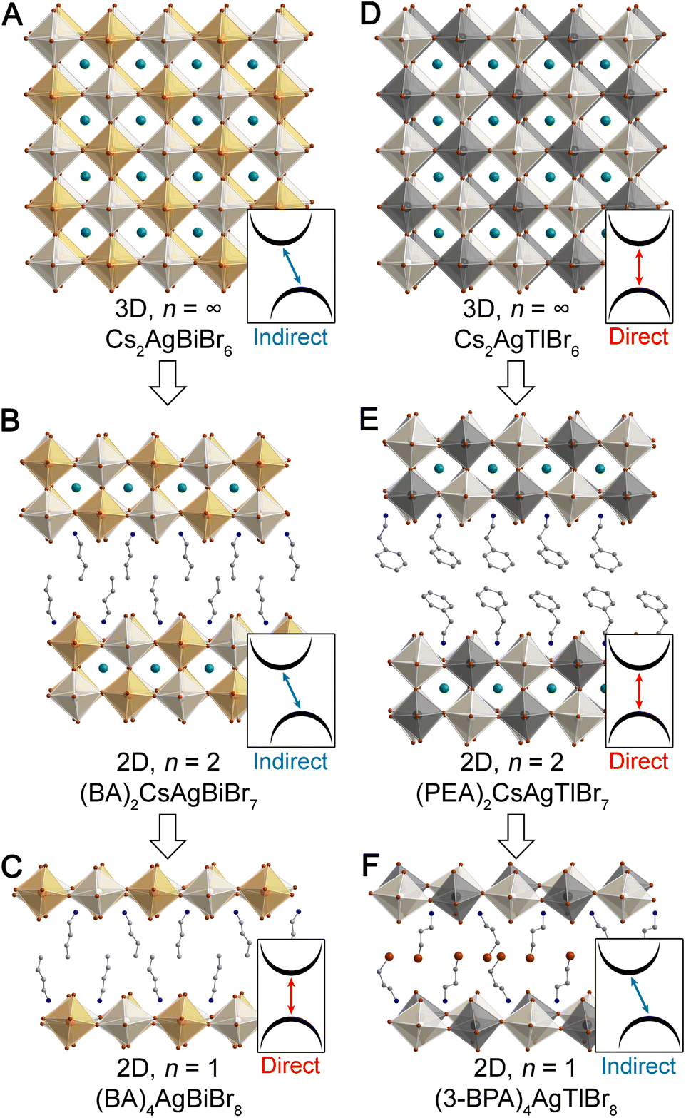 | ||
| Fig. 1 Single-crystal X-ray diffraction structures of the 3D double perovskites Cs2AgBiBr6 (ref. 22) (A) and Cs2AgTlBr6 (ref. 23) (D), their n = 2 analogues, (BA)2CsAgBiBr7 (ref. 13) (B) and (PEA)2CsAgTlBr7 (ref. 15) (E), and their n = 1 analogues, (BA)4AgBiBr8 (ref. 13) (C) and (3-BPA)4AgTlBr8 (ref. 15) (F). (BA = butylammonium, PEA = phenethylammonium, 3-BPA = 3-bromopropylammonium). Insets indicate the direct/indirect nature of the bandgap of each perovskite. Orange, black, white, teal, brown, blue, and gray spheres represent Bi, Tl, Ag, Cs, Br, N, and C atoms, respectively. H and disordered atoms omitted for clarity. | ||
One of the most intriguing findings to emerge from work on double perovskites has been the observation of substantial changes in electronic structure upon dimensional reduction. In contrast to 2D single perovskites, which show band structures analogous to their 3D analogues (albeit with the expected reduction in band dispersion),11 dimensional reduction produces a dramatic shift in bandgap symmetry when the 3D double perovskites Cs2AgBiBr6 (ref. 22) and Cs2AgTlBr6 (ref. 23) are reduced to monolayer thickness in the n = 1 perovskites.13,15 We refer to the two k points that define the valence band maximum (VBM) and conduction band minimum (CBM) for a given electronic structure as the bandgap symmetry; a change in the k points of at least one of these band extrema affords a bandgap symmetry transition.
The indirect bandgap of Cs2AgBiBr6 (Fig. 1A) has been shown through experiment and theory, and DFT calculations reveal that an analogous indirect gap is maintained in all structures with n ≥ 2. However, the n = 1 Ag–Bi perovskite (Fig. 1C) is calculated to have a direct bandgap. Although electronically distinct from Cs2AgBiBr6, we see a similar bandgap symmetry transition with dimensional reduction of Cs2AgTlBr6 (Fig. 1D). Here, a direct gap is seen for all structures with n ≥ 2, yet an indirect gap is calculated for the n = 1 Ag–Tl structure (Fig. 1F). Notably, the Ag–In perovskites behave similarly to the isoelectronic Ag–Tl perovskites, with a direct gap calculated for the 3D lattice and an indirect gap calculated for the n = 1 lattice.15
Layered perovskites typically show distortions not seen in the cubic 3D materials. Calculations on undistorted model Ag–Bi and Ag–Tl systems, obtained by excising slices from the cubic 3D lattice, demonstrate that the changes in band structure are driven by dimensional reduction, rather than by the structural distortions of the layered perovskite lattice.13,15 However, an understanding of the underlying orbital basis for the bandgap symmetry transitions with dimensional reduction is still lacking. Such insight is critical for assessing the generality of this phenomenon across the rapidly expanding array of double perovskite compositions and for predicting which compositions are likely to feature this effect.
Here, we adapt the linear combination of atomic orbitals (LCAO) approach that we previously developed for 3D double perovskites24 to the 2D n = 1 and 2 derivatives. We describe several important modifications to this analysis that are required for the 2D case and then demonstrate our approach by mapping out the band structures of the undistorted n = 1 and 2 Ag–Bi and Ag–Tl structures, finding good agreement between our predictions and DFT calculations. This work establishes an understanding of the orbital basis of the band structures of the 2D Ag–Bi and Ag–Tl perovskites. We use this understanding to identify two factors that drive the bandgap symmetry transition at the n = 1 limit: (i) the 2D translational symmetry of the layered structures and (ii) the stronger interaction of metal orbitals with terminal halides than with bridging halides. Importantly, our analysis reveals that dimensional reduction will not change the bandgap symmetry for all double perovskite compositions—only for those where metal d orbitals contribute to the band edges or those with no metal orbital character in the valence band.
2. Results
We begin with a brief summary of our previous work24 where we applied an LCAO approach to derive the essential features of 3D double perovskite band structure as these concepts provide a helpful roadmap for this work. For a detailed introduction to the LCAO method applied to solids, the reader is referred to the seminal text by Hoffmann.252.1 Key concepts from the LCAO analysis of 3D double perovskites
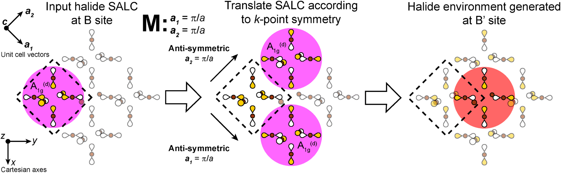
In our analysis of the 3D lattices, we first generated symmetry adapted linear combinations (SALCs) of the six σ-bonding halide p orbitals surrounding the B site of the double perovskite lattice based on the Oh point symmetry of their arrangement (Fig. 2A). Positioning a given SALC about the B site, we then carried out symmetric or antisymmetric translations of this SALC to adjacent B sites according to the translational symmetry rules of the high-symmetry k points of the double perovskite lattice, generating a set of 3D halide Bloch waves. Each Bloch wave preserves the symmetry of the starting SALC at the B site, but the different translational symmetry rules of each k point produce differing symmetries and thus different halide orbital environments at the adjacent B′ site (Fig. 2B). Because the SALC at the B site is unchanging, the bonding/antibonding interactions at the B′ site determine the relative energies of this set of Bloch waves. Thus, the interactions at the B′ site map out the dispersion of the band derived from the starting SALC placed at the B site (Fig. 2C).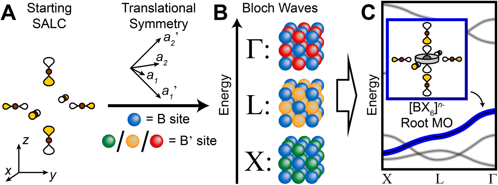 | ||
| Fig. 2 Outline of the LCAO approach used in this work. A halide SALC (A) is propagated across the lattice generating a series of halide Bloch waves of varying energies (B). Blue spheres represent the unchanging halide orbital environment (halide SALC) at the B site whereas green, yellow, and red spheres represent the different halide orbital environments produced at the B′ site. The energetic ranking of these Bloch waves, including their interactions with B′-site metal orbitals, determines the dispersion of the band derived (C). The metal orbital + starting SALC combination present throughout the band is designated as the root MO of the band (C, inset). One of the Eg halide SALCs for the 3D lattice24 is shown in (A). Brown and gray circles represent halide and metal atoms, respectively. Yellow and white lobes represent the phases of the σ-bonding halide p orbitals and are scaled to give an approximate sense of relative electron density. | ||
In the following, we adapt this analysis to n = 1 and 2 double perovskites, placing particular emphasis on aspects that must be altered or are entirely new for the 2D lattices. Since we previously determined that structural distortions of the perovskite lattice are not the driving force behind the change in band structure observed in the Ag–Bi and Ag–Tl perovskites,13,15 we perform our analysis on undistorted n = 1 and 2 double perovskites assuming bond lengths and angles equal to those found in the cubic parent 3D double perovskite (Fig. 1A and D). Nevertheless, the band structures derived for these model systems can be used as starting points for forecasting how distortions observed in experimental structures (Fig. 1B, C, E and F) alter band dispersion, as we have demonstrated previously.13
Since at least one of the frontier orbitals of the metal cations of both the Ag–Bi and Ag–Tl perovskites are capable of forming strong σ interactions with the surrounding halide p orbitals, the most important features of the conduction and valence bands can be derived by considering only the σ-bonding states. Nevertheless, the methodology presented for the σ-bonding states can be extended to π-bonding states to accommodate cases where π-bonding dyz/dxz/dxy metal orbitals contribute to the band edges. This analysis is provided in ESI Section S6.†
2.2 LCAO analysis for undistorted n = 1 perovskites
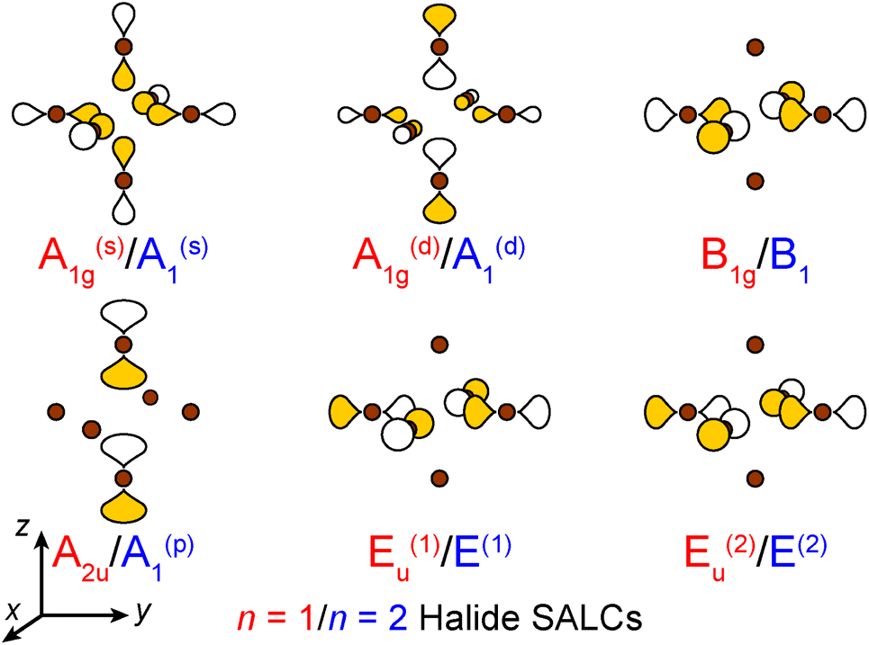 | ||
| Fig. 3 The six σ-bonding halide SALCs for the n = 1 and 2 perovskites with their symmetry labels shown in red and blue, respectively. Brown spheres represent halide atoms. The yellow and white p orbital lobes represent positive and negative phases, respectively and are scaled to give an approximate sense of relative electron density. The two degenerate Eu/E orbitals are drawn as linear combinations of the SALCs with px and py symmetry (see ESI† for details). | ||
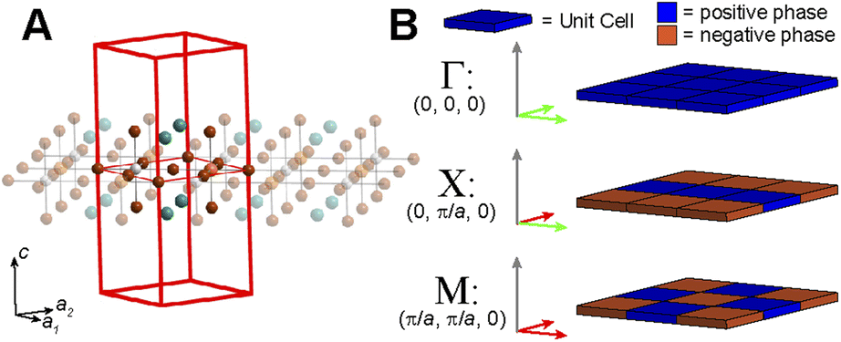 | ||
| Fig. 4 (A) The tetragonal unit cell of an undistorted n = 1 halide double perovskite. Orange, white, brown, and teal spheres represent the B- and B′-site cations, halides, and A-site cations, respectively. (B) The translational symmetry of the high-symmetry k points of a primitive tetragonal lattice. The two different phases of the unit cells are represented in blue and orange. Green and red arrows represent in-phase and out-of-phase translations, respectively, of the starting SALC along the corresponding lattice vector. | ||
Placing a halide SALC at the B site, we can translate it along a1 and a2 to adjacent B sites, thus propagating our starting SALC across the perovskite lattice to generate a halide Bloch wave. We perform these translations either symmetrically (in-phase) or antisymmetrically (out-of-phase) according to the coordinates of the high-symmetry k points of the tetragonal lattice. Bonding/antibonding interactions are maximized at these high-symmetry points, leading to the formation of band extrema. Here, we consider the k points Γ = (0, 0, 0), M = (π/a, π/a, 0), and X = (0, π/a, 0). A coordinate of 0 calls for a symmetric translation of our starting SALC along the corresponding lattice vector whereas a coordinate of π/a calls for an antisymmetric translation (Fig. 4B). Fig. 5 shows a top-down view of the n = 1 perovskite lattice, illustrating the procedure for generating a Bloch wave from a starting SALC of A1g(d) symmetry at the M point. Repeating this procedure for each starting SALC in Fig. 3 at the three high-symmetry k points generates 18 halide Bloch waves (Fig. S25–S42†) which are summarized in Fig. 6 by showing the halide orbitals around adjacent B and B′ sites. Note that, unlike in the 3D case, no axial halides are generated at the B′ site by translational symmetry since there are no B sites above or below the B′ sites. This has important consequences for the band structure of the n = 1 perovskites as discussed below.
 | ||
| Fig. 5 Example of the procedure for propagating a halide SALC across the n = 1 perovskite lattice to generate a halide Bloch wave. Here, we begin with an A1g(d) SALC at the B site (highlighted in pink) and translate anti-symmetrically (flipping the orbital phases) along the two in-plane unit-cell vectors (a1 and a2) according to the coordinates of the M point generating the halide environment at the B′ site (highlighted in red, with Eg point symmetry). The relative size of p orbitals is kept uniform for simplicity. Yellow and white lobes represent positive and negative phases, respectively. Brown spheres represent halide atoms. | ||
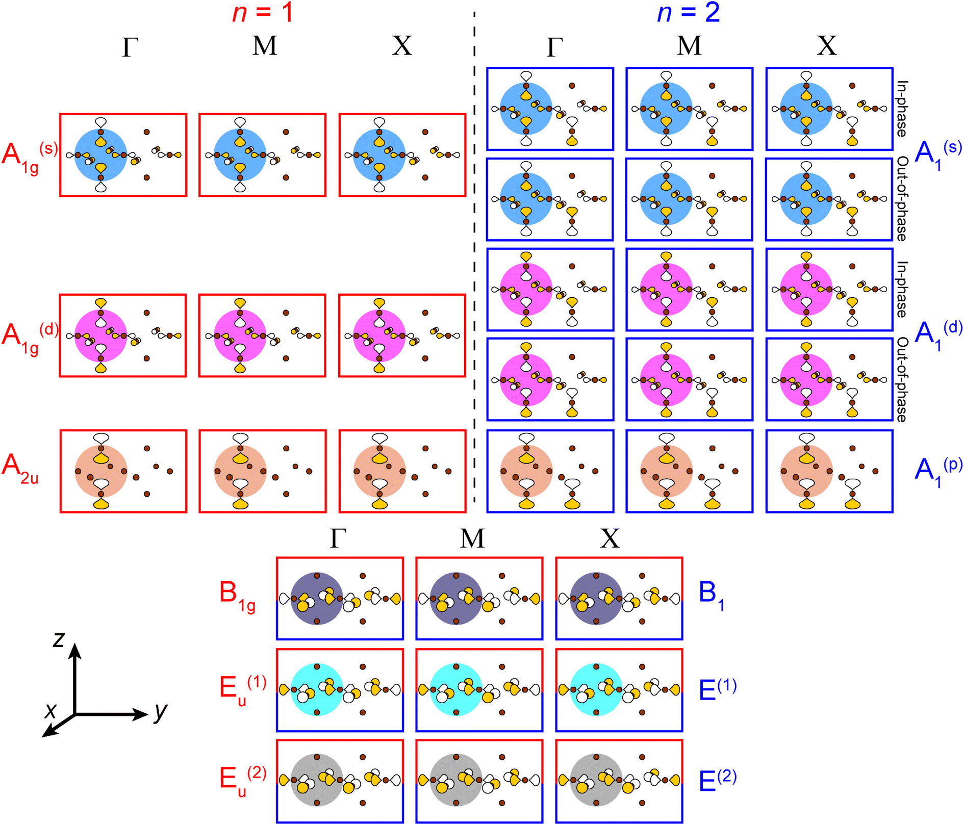 | ||
| Fig. 6 A summary of all unique n = 1 and 2 halide Bloch waves (outlined in red and blue, respectively) at the Γ, M, and X points. Derivations are given in the ESI.† The n = 1 B1g and Eu(1,2) Bloch waves have halide orbital environments at the B and B′ sites that are identical to the n = 2 B1 and E(1,2) Bloch waves, respectively, and are shown together (red and blue box). Additionally, in cases where the in-phase and out-of-phase combinations of the starting SALC give the same set of n = 2 Bloch waves, we show this set only once. The p orbital lobes are scaled to represent approximate relative electron densities. Yellow and white lobes represent positive and negative phases, respectively. Brown spheres represent halide atoms. | ||
It is important to emphasize the distinction we draw between the B- and B′-site cations. Either of the two metal cations of a given double perovskite composition (e.g., Ag+ or Bi3+ in Cs2AgBiBr6) could be considered the B-site or the B′-site cation, depending on which band we are considering. The cation that forms the [BX6]n− root MO of the band under consideration (the metal cation enclosed by the starting halide SALC; e.g., Ag+) is considered the B-site occupant. The other (i.e., Bi3+) is considered the B′-site occupant (the metal cation surrounded by the halide orbitals generated through translational symmetry; Fig. 5). However, if we consider a different band where Bi3+ participates in the [BX6]n− root MO, the assignment would be reversed: Bi3+ and Ag+ would be the B- and B′-site cations, respectively. Additionally, in all figures depicting halide Bloch waves, the B and B′ sites are shown on the left and right sides, respectively.
For each band, we identify the three Bloch waves in Fig. 6 (at Γ, M, and X) derived from the halide SALC of the band's root MO. Since these three Bloch waves have identical interactions at the B site, their energetic ranking, and hence the dispersion of the band, is determined by the bonding/non-bonding/antibonding interactions at the B′ site. The strongest interactions are B′–X interactions between a frontier orbital of the B′ cation (with an appropriate energy to participate in the band) and the surrounding halide p orbitals of matching symmetry (Fig. 7A). In the absence of such B′–X interactions, weaker X–X interactions between halide orbitals surrounding the B′ site determine the energy of the Bloch wave (Fig. 7A). Our prior work showed that interactions between adjacent halides positioned at 90° with respect to one another (90° X–X interactions) are more important than those between the more distant halides positioned at 180° with respect to one another (180° X–X interactions),24 so here, we consider only the former.
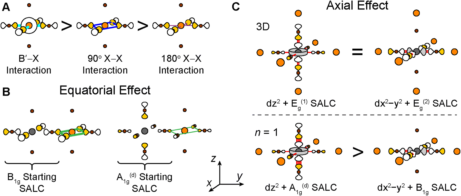 | ||
| Fig. 7 (A) Relative strength of the B′–X, 90° X–X, and 180° X–X interactions present at the B′ site. (B) Illustration of the equatorial effect. Green lines indicate bonding 90° X–X interactions and the line thickness indicates that interactions formed in the B1g-derived Bloch wave are stronger than in the A1g(d)-derived Bloch wave. (C) Illustration of the axial effect. The terminal axial halides of the n = 1 structure can interact more strongly with the metal center than the bridging equatorial halides, increasing the energy of the dz2–A1g(d) antibonding combination relative to the dx2−y2–B1g antibonding combination (bottom panel). The analogous combinations for the 3D structure are isoenergetic (top panel). The number of red lines denotes the approximate strength of the antibonding interactions. Gray, orange, and brown spheres represent B cations, B′ cations, and halides, respectively. Orbital lobes are shaded to denote relative phases. | ||
2.3 Case study 1: the Ag–Bi n = 1 perovskite
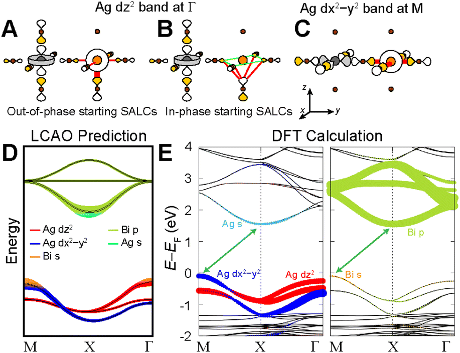
Below, we demonstrate this analysis for the undistorted n = 1 Ag–Bi perovskite. A similar analysis of the structurally analogous but electronically distinct Ag–Tl perovskite can be found in the ESI Section S5.1.†The three high-symmetry Bloch waves for the Ag dz2 band (where the dz2 orbital participates in the root MO) are shown in Fig. 8A–C, arranged in order of increasing energy from left to right. The highest-energy Bloch wave occurs at Γ, where the 90° interactions between halide p orbitals (90° X–X interactions) are all in-phase at the Bi site, enabling strong σ-antibonding interactions with the filled 6s orbital of Bi3+ (Fig. 8C). (Based on the contribution of Bi 6s orbitals to the VBM of Cs2AgBiBr6, these states are located at an appropriate energy to participate in the band.)24 The Bi 6s orbitals do not have the required symmetry to contribute at M or X, so we rank these Bloch waves based on the weaker 90° X–X interactions around the Bi site. The antibonding configuration at M (Fig. 8B) and the non-bonding configuration at X (Fig. 8A) give an overall energetic ordering of the k points of Γ > M > X.
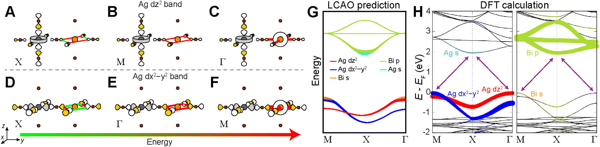 | ||
| Fig. 8 LCAO analysis for the n = 1 Ag–Bi structure. LCAO representations of the Ag dz2 derived valence band (VB) at the X (A), M (B), and Γ (C) points ranked in order of increasing energy from left to right. LCAO representations of the Ag dx2−y2 derived VB at the X (D), Γ (E), and M (F) points ranked in order of increasing energy from left to right. Bonding and antibonding interactions at the B′ site are shown as green and red lines, respectively, and the thickness of each line corresponds to the strength of the interaction. Halide p orbital lobes are scaled to represent approximate relative electron densities and the shading of orbital lobes denote their relative phases. Gray, orange, and brown spheres represent Ag, Bi, and Br atoms, respectively. (G) Predicted band diagram of the n = 1 Ag–Bi structure using our LCAO analysis. (H) DFT band structure of the n = 1 Ag–Bi structure without SOC. The band structure is shown in duplicate where the Ag (left panel) and Bi (right panel) states that compose the bands are represented by colored dots. | ||
Fig. 8D–F shows the three Bloch waves for the Ag dx2−y2 band. Here, the highest energy is found at M where the Bloch wave has the correct symmetry at the B′ site to have antibonding interactions with the Bi 6s orbital (Fig. 8F). The antibonding and non-bonding 90° X–X interactions found at Γ and X, respectively (Fig. 8D and E), yield an overall energetic ordering of the k points of M > Γ > X.
Having predicted the dispersion pattern for the Ag dz2 and dx2−y2 bands, we now must evaluate the relative energies of these two bands. The Bi s orbitals contribute antibonding character to the maxima of both bands. However, due to the equatorial effect (Section 2.2.5), the B1g-derived Bloch wave of the dx2−y2 band will interact more strongly with the Bi s orbital than the A1g(d)-derived Bloch wave of the dz2 band (Fig. 8C and F). Thus, the equatorial effect increases the energy of the dx2−y2 band at M relative to the dz2 band at Γ.
At the same time, the axial effect (Section 2.2.6) pushes the entire dz2 band up in energy relative to the dx2−y2 band. In the absence of the axial effect, the dz2 and dx2−y2 bands would be isoenergetic at the X point where both have non-bonding 90° X–X interactions around the B′ site. Indeed, this is the case in 3D Cs2AgBiBr6 (at the L point, see Fig. S15†).24 However, due to the axial effect, we predict that in the n = 1 structure, the Ag dz2 band is higher in energy than the Ag dx2−y2 band at X (Fig. 8G).
Clearly the axial and equatorial effects will compete to determine the location of the VBM in the n = 1 Ag–Bi perovskite; the equatorial effect boosts the maximum of the dx2−y2 band, whereas the axial effect raises the energy of the entire dz2 band. It is not possible to say which effect will dominate using our qualitative model, so for now we will assume that they are equal, generating isoenergetic VBMs at M and Γ. We diagram our predicted band dispersion for the highest energy VBs of the n = 1 Ag–Bi structure in Fig. 8G.
The A2u SALC involves only the two axial halide p orbitals at the B site, which have no translational symmetry equivalents at the B′ site. As a result, there are no halide orbitals around the B′ sites in the A2u-derived Bloch waves so all three are isoenergetic, giving a band with no dispersion (Fig. 8G).
Our predictions for the CB are also in good qualitative agreement with the DFT calculations, which shows two Bi p-based bands that display a large splitting at X and a third that has very little dispersion. It is important to point out that the DFT band structure in Fig. 8H was calculated without accounting for spin-orbit coupling (SOC) because our model is a non-relativistic one, which does not consider SOC effects. However, SOC has a substantial impact on the dispersion pattern of the Bi 6p-based CB and we refer the interested reader to the ESI Section S4† for a discussion of this point.
2.4 LCAO analysis for undistorted n = 2 perovskites
In the sections below, we describe how the analysis outlined above can be extended to n = 2 structures.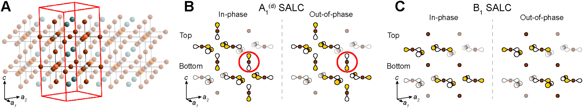 | ||
| Fig. 9 (A) Unit cell of an n = 2 double perovskite. Orange, white, brown, and teal spheres represent the B- and B′-site cations, halides, and A-site cations, respectively. In-phase and out-of-phase combinations of the A1(d) (B) and B1 (C) halide SALCs. Brown spheres represent Br atoms. Yellow and white shading of the p orbital lobes denotes their relative phase. For simplicity, the relative size of p orbitals is kept uniform. Circled axial halide orbitals highlight the different halide orbital environments generated at the B′ site depending on the phase difference of the starting SALCS (in-phase vs. out-of-phase). | ||
2.5 Case study 2: the Ag–Bi n = 2 perovskite
 | ||
| Fig. 10 LCAO representation of the dz2- and dx2−y2-derived valence bands of the n = 2 Ag–Bi structure at Γ (A and B) and M (C), respectively. Bonding and antibonding interactions at the B′ site are shown as green and red lines, respectively, where line thickness indicates the strength of the interaction. Gray, orange, and brown spheres represent Ag, Bi, and Br atoms, respectively. Halide p orbital lobes are scaled to represent approximate relative electron densities and their shading denotes their relative phase. (D) Predicted band structure of the n = 2 Ag–Bi structure. Double black lines indicate degenerate bands. (E) DFT band structure for the n = 2 Ag–Bi structure calculated without SOC. The band structure is shown in duplicate where the Ag (left panel) and Bi (right panel) states that compose the bands are represented by colored dots. | ||
Due to the equatorial effect, Bi s orbitals introduce more antibonding character to the dx2−y2 band at M (Fig. 10C) than to the dz2 band at Γ (Fig. 10A), raising the energy of the VBM at M relative to Γ. At the same time, the axial effect raises the energy of the entire dz2 band relative to the dx2−y2 band. The magnitudes of these effects are expected to be reduced compared to the n = 1 case (Section 2.4.4) though it is difficult to predict the relative magnitudes of these reductions. Thus, our predictions in Fig. 10D assume that they are reduced by the same amount and therefore, remain equally important (as in the n = 1 analogue), resulting in isoenergetic VBMs at M and Γ.
3. Discussion
The approach presented above affords an understanding of the molecular-level interactions that determine the band structure of the 2D Ag–Bi perovskites (and Ag–Tl perovskites; see ESI Section S5†), positioning us to identify the factors driving the change in bandgap symmetry observed at the n = 1 limit in both systems.3.1 3D vs. 2D translational symmetry
The switch from 3D to 2D translational symmetry plays an important role in the bandgap symmetry transition of the n = 1 Ag–Bi and Ag–Tl perovskites. Translational symmetry of the layered perovskites is defined in terms of two orthogonal unit-cell vectors lying in the xy plane (Fig. 11A). These same two vectors describe translations within the xy plane of the 3D lattice, while an identical set rotated by 90° define translations in the yz plane (Fig. 11B, see Fig. S19† for vector derivation).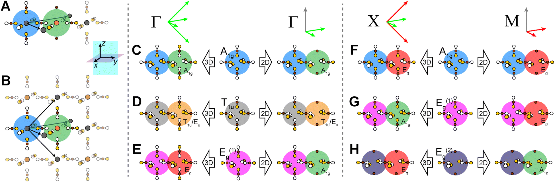 | ||
| Fig. 11 Consequences of 3D vs. 2D translational symmetry. Translational symmetry vectors of the 2D (A) and 3D (B) double perovskite lattices. Bloch waves generated at the 3D and 2D Γ points for the A1g (C), T1u (D), and Eg(1) (E) starting SALCs. Bloch waves generated at the 3D X point and 2D M point for the A1g (F), Eg(1) (G), and Eg(2) (H) starting SALCs. Red and green vectors represent antisymmetric and symmetric translations, respectively. The color of the shaded circle behind each B′ site indicates the symmetry of the halide environment generated there by translational symmetry (green = A1g, yellow = T1u/Eu, red = Eg). For simplicity, here we use the halide SALCs of the 3D lattice and the size of orbital lobes is kept uniform. Gray, orange, and brown spheres represent B-site cations, B′-site cations, and halide atoms, respectively, and the shading of p orbital lobes represents relative phase. | ||
The simplified band diagrams shown in Fig. 12A and B (which omit the influence of the axial and equatorial effects) demonstrate how the differences in 3D and 2D translational symmetry result in distinct band structures for the 3D and 2D lattices in the Ag–Tl and Ag–Bi systems. Specifically, we observe very different dispersion patterns for the Ag d-based VBs of the 3D and 2D lattices, but the dispersion patterns of the lowest-lying Tl s- and Bi p-derived CBs are identical in the 3D and 2D structures. In the sections below, we explain the origins of these differences.
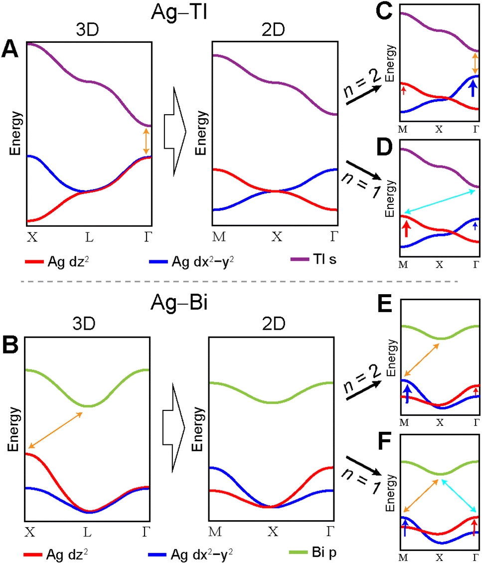 | ||
| Fig. 12 Diagrams illustrating the dispersion of the valence and conduction bands of the Ag–Tl and Ag–Bi perovskites. Panels A and B demonstrate the changes in dispersion of the Ag dz2 and dx2−y2 bands caused by switching from 3D to 2D translational symmetry. Panels C–F illustrate the changes in the Ag dz2 and dx2−y2 bands caused by the axial (red arrows) and equatorial (blue arrows) effects. Note that these diagrams represent simplified band structures; some bands and orbital contributions are omitted for clarity. | ||
In contrast to the A1g and T1u SALCs, the two Eg SALCs do not have equivalent halide orbital environments in the xy and yz planes. For example, in the Eg(1) SALC, the halide p orbitals in the xy plane are all in-phase whereas in the yz plane adjacent halide p orbitals are out-of-phase with one another. As a result, translation of the Eg SALCs across the xy plane of the 2D lattice produces a set of Bloch waves distinct from those generated by translation across the xy and yz planes of the 3D lattice (i.e., some of the 2D Bloch waves have halide orbital environments at the B′ site with a different symmetry than for their respective 3D analogues, Fig. S22 and S23†). Therefore, bands derived from these Bloch waves will show different patterns of dispersion in the 2D and 3D lattices, explaining why the Ag dz2- and dx2−y2-based VBs shown in Fig. 12A and B change upon dimensional reduction. Below, we give several examples to illustrate why the Eg SALCs produce different patterns of band dispersion in the 3D and 2D lattices.
3.2 The axial effect vs. the equatorial effect
We have shown that 2D translational symmetry alters the dispersion pattern of the Ag d-orbital-based VBs in both the Ag–Tl and Ag–Bi perovskites, but that alone does not explain the change in bandgap symmetry at the n = 1 limit. Below, we add the influence of the axial and equatorial effects to show how the interplay of these three factors can explain the observed bandgap transitions.Although our LCAO analysis predicts an abrupt change in bandgap symmetry at the n = 1 limit of the Ag–Bi perovskite and agrees with the DFT calculations presented here, these results do not capture the direct bandgap at Γ that we previously reported for the n = 1 perovskite.13 This is because our theory is a non-relativistic one, which cannot account for SOC. Including SOC in the DFT calculations substantially alters the dispersion of the Bi p-based CBs, generating a CBM at Γ that is 150 meV lower than that at X and producing a direct gap at Γ (Fig. S3†). Thus, a direct gap is attained at the n = 1 limit due to the effects of dimensional reduction and SOC.
3.3 The role of metal d orbitals and d-orbital symmetry
The interplay of 2D translational symmetry, the equatorial effect, and the axial effect is critical for determining the bandgap symmetry of the n = 1 and 2 Ag–Bi and Ag–Tl perovskites. However, from the discussion in Sections 2.2.5, 2.2.6, and 3.1 it is clear that all three of these factors are relevant for bands derived from B-site metal dz2 and dx2−y2 orbitals but not for those based on B-site metal s and p orbitals. In the ESI Section S6,† we extend our analysis to π-bonding states, finding that 2D translational symmetry, the equatorial effect, and the axial effect are also important considerations for bands based on the π-bonding metal dyz, dxz, and dxy orbitals. This allows us to make the more general statement that any band based on a B-site metal d orbital is expected to undergo changes in dispersion pattern upon dimensional reduction. We also demonstrate in ESI Section S8† that d orbital contributions at the B′ site can lead to different patterns of dispersion in the 2D and 3D lattices.The changes to metal d-orbital-derived bands observed upon dimensional reduction are all rooted in the inequivalence of the halide orbital environments found in the xy and yz planes of the 3D halide SALCs with d-orbital symmetry that compose these bands (Section 3.1). Thus, we can make the more general statement that a band derived from any 3D SALC having different halide orbital environments in the xy and yz planes will undergo a change in dispersion pattern upon dimensional reduction, thereby encompassing bands to which no metal orbitals contribute. A number of SALCs, including all of those with d-orbital symmetry, meet this requirement, but most relevant to consider are those capable of forming the most antibonding 90° X–X interactions (the 3D Eg(1,2) and T1g SALCs and a subset of their 2D analogues: the A1g(d), B1g, and A2g SALCs; see ESI Sections S6.5 and S9†) because these will constitute the highest VBs of double perovskite compositions where both B-site cations have low-lying HOMOs and do not contribute to the valence band edges. However, note that such perovskites will have relatively flat bands, making changes in bandgap symmetry is less significant than in compositions where both B-site metals contribute.
To summarize, we expect that only double perovskite compositions in which metal d orbitals contribute at the band edges or in which no metal orbitals contribute to the VB are likely to display a change in bandgap symmetry upon dimensional reduction. Indeed, (CH3NH3)2TlBiBr6, a double perovskite where only metal s and p orbitals contribute to the band edges, shows no substantial changes in band structure upon dimensional reduction (Fig. S24†).
4. Conclusions
The direct-to-indirect bandgap transition of 3D Cs2AgTlBr6, as it is thinned to a monolayer in the n = 1 2D perovskite, as well as the indirect-to-direct bandgap transition as 3D Cs2AgBiBr6 is dimensionally reduced to an n = 1 2D perovskite have been shown through DFT calculations.13,15 However, an explanation for why these bandgap symmetry transitions occur only in certain double perovskite compositions has been lacking. Achieving such an understanding may yield guidelines on which double perovskite compositions are likely to show such a transition with dimensional reduction.To address this question, and to improve our understanding of this emerging family of materials, we have developed an LCAO analysis for 2D double perovskites that uncovers the orbital basis for the changes in bandgap symmetry with dimensional reduction. We describe several considerations needed for the LCAO analysis of 2D double perovskites. In particular, we highlight the importance of (a) 2D translational symmetry, which results in the axial (terminal) halides at the B site not being translated to the B′ site, and (b) the “axial effect”, which describes the consequences of stronger interactions between the B-site metal orbitals and the axial (terminal) halides compared to those with the equatorial (bridging) halides. These considerations, irrelevant for the LCAO analysis of 3D perovskites,24 form the basis for the change in bandgap symmetry upon dimensional reduction from the 3D Cs2AgBiBr6 and Cs2AgTlBr6 perovskites to the 2D analogues. Specifically, 2D translational symmetry moves the maximum of the Ag dz2-based valence band (VB) away from its location in the 3D analogue, and the axial effect raises the energy of this band, creating a new valence band maximum (VBM).
Our analysis does not account for spin-orbit coupling (SOC), which can change the band dispersion patterns of certain double perovskite compositions, as discussed in the ESI Section S4.† Nevertheless, our simple treatment can capture many of the relevant factors that dictate the bandgaps of layered double perovskites, and importantly, helps develop the intuition of synthetic chemists targeting new double perovskite compositions that show this bandgap symmetry transition. We therefore highlight the key take-away from our analysis: only double perovskite compositions that involve participation of metal d orbitals at the band edges or that have no metal-orbital contributions to the VB are expected to display changes in bandgap symmetry upon dimensional reduction due to the inequivalent halide orbital environments found in the xy and yz planes of the halide SALCs involved in these cases. Such a bandgap symmetry transition is a necessary, though not sufficient, condition for a direct → indirect or an indirect → direct bandgap transition.
Similarly, the change in bandgap symmetry observed at the monolayer limit of MoS2 has been traced to differences in axial and equatorial interactions. Here, electronic states comprised of orbitals with large axial components (perpendicular to the plane of the 2D sheets, like Mo dz2) have strong interlayer interactions and therefore undergo a large energetic perturbation upon exfoliation. In contrast, states based on orbitals with electron density primarily in the xy plane of the 2D sheet (like Mo dx2−y2 orbitals) have weak interlayer interactions and will not be significantly affected by exfoliation.30 Thus, the inequivalence of metal d-orbital interactions in the axial and equatorial directions drives the indirect-to-direct bandgap transition upon dimensional reduction observed in MoS2, similar to our findings for double perovskites presented here.
This study lays the groundwork for using dimensional reduction as a predictable means of changing the direct/indirect nature of the bandgap in other double perovskite compositions.
Data availability
Symmetry-Adapted Linear Combinations of atomic orbitals (SALCs)/Bloch waves derived through the analysis presented here and band structures from DFT calculations are available in the ESI.†Author contributions
The 2D LCAO analysis was developed by B. A. C. with contributions from all authors. L. L. performed the DFT calculations. The manuscript was written by B. A. C. and H. I. K. with contributions from all authors.Conflicts of interest
There are no conflicts to declare.Acknowledgements
This work was supported by the National Science Foundation (NSF; DMR2102306) and the Brown Science Foundation. B. A. C. acknowledges support from an NSF graduate research fellowship (DGE-114747) and the Evelyn McBain award from Stanford Chemistry. A. C. S. acknowledges support from the NSF (DMR2102306) and the John Stauffer Stanford Graduate Fellowship. The computational work was supported by the Dutch Research Council (NWO) under Grant OCENW.M20.337. L. L. also acknowledges funding by the Bavarian State Ministry of Science and the Arts through the Elite Network of Bavaria, the German Research Foundation through SFB840 B7, and computational resources provided by the Bavarian Polymer Institute.Notes and references
- A. Splendiani, L. Sun, Y. Zhang, T. Li, J. Kim, C.-Y. Chim, G. Galli and F. Wang, Emerging Photoluminescence in Monolayer MoS2, Nano Lett., 2010, 10, 1271–1275 CrossRef CAS PubMed.
- K. F. Mak, C. Lee, J. Hone, J. Shan and T. F. Heinz, Atomically Thin MoS2: A New Direct-Gap Semiconductor, Phys. Rev. Lett., 2010, 105, 136805 CrossRef PubMed.
- D. Jariwala, V. K. Sangwan, L. J. Lauhon, T. J. Marks and M. C. Hersam, Emerging Device Applications for Semiconducting Two-Dimensional Transition Metal Dichalcogenides, ACS Nano, 2014, 8, 1102–1120 CrossRef CAS PubMed.
- S. Manzeli, D. Ovchinnikov, D. Pasquier, O. V. Yazyev and A. Kis, 2D transition metal dichalcogenides, Nat. Rev. Mater., 2017, 2, 17033 CrossRef CAS.
- T. F. Jaramillo, K. P. Jørgensen, J. Bonde, J. H. Nielsen, S. Horch and I. Chorkendorff, Identification of Active Edge Sites for Electrochemical H2 Evolution from MoS2 Nanocatalysts, Science, 2007, 317, 100–102 CrossRef CAS PubMed.
- D. B. Mitzi, Templating and structural engineering in organic–inorganic perovskites, J. Chem. Soc., Dalton Trans., 2001, 1–12, 10.1039/b007070j.
- B. Saparov and D. B. Mitzi, Organic−Inorganic Perovskites: Structural Versatility for Functional Materials Design, Chem. Rev., 2016, 116, 4558–4596 CrossRef CAS PubMed.
- T. Ishihara, Optical properties of PbI-based perovskite structures, J. Lumin., 1994, 60–61, 269–274 CrossRef CAS.
- M. D. Smith, B. A. Connor and H. I. Karunadasa, Tuning the Luminescence of Layered Halide Perovskites, Chem. Rev., 2019, 119, 3104–3139 CrossRef CAS PubMed.
- I. C. Smith, E. T. Hoke, D. Solis-Ibarra, M. D. McGehee and H. I. Karunadasa, A Layered Hybrid Perovskite Solar-Cell Absorber with Enhanced Moisture Stability, Angew. Chem., Int. Ed., 2014, 53, 11232–11235 CrossRef CAS PubMed.
- N. R. Wolf, B. A. Connor, A. H. Slavney and H. I. Karunadasa, Doubling the Stakes: The Promise of Halide Double Perovskites, Angew. Chem., Int. Ed., 2021, 60, 16264–16278 CrossRef CAS PubMed.
- L. M. Castro-Castro and A. M. Guloy, Organic-Based Layered Perovskites of Mixed-Valent Gold(I)/Gold(III) Iodides, Angew. Chem., Int. Ed., 2003, 42, 2771–2774 CrossRef CAS PubMed.
- B. A. Connor, L. Leppert, M. D. Smith, J. B. Neaton and H. I. Karunadasa, Layered Halide Double Perovskites: Dimensional Reduction of Cs2AgBiBr6, J. Am. Chem. Soc., 2018, 140, 5235–5240 CrossRef CAS PubMed.
- L. Mao, S. M. L. Teicher, C. C. Stoumpos, R. M. Kennard, R. A. DeCrescent, G. Wu, J. A. Schuller, M. L. Chabinyc, A. K. Cheetham and R. Seshadri, Chemical and Structural Diversity of Hybrid Layered Double Perovskite Halides, J. Am. Chem. Soc., 2019, 141, 19099–19109 CrossRef CAS PubMed.
- B. A. Connor, R.-I. Biega, L. Leppert and H. I. Karunadasa, Dimensional reduction of the small-bandgap double perovskite Cs2AgTlBr6, Chem. Sci., 2020, 11, 7708–7715 RSC.
- L.-Y. Bi, Y.-Q. Hu, M.-Q. Li, T.-L. Hu, H.-L. Zhang, X.-T. Yin, W.-X. Que, M. S. Lassoued and Y.-Z. Zheng, Two-dimensional lead-free iodide-based hybrid double perovskites: crystal growth, thin-film preparation and photocurrent responses, J. Mater. Chem. A, 2019, 7, 19662–19667 RSC.
- E. T. McClure, A. P. McCormick and P. M. Woodward, Four Lead-free Layered Double Perovskites with the n = 1 Ruddlesden–Popper Structure, Inorg. Chem., 2020, 59, 6010–6017 CrossRef CAS PubMed.
- M. L. Aubrey, A. Saldivar Valdes, M. R. Filip, B. A. Connor, K. P. Lindquist, J. B. Neaton and H. I. Karunadasa, Directed assembly of layered halide perovskite heterostructures as single crystals, Nature, 2021, 597, 355–359 CrossRef CAS PubMed.
- P. Vishnoi, J. L. Zuo, X. Li, D. C. Binwal, K. E. Wyckoff, L. Mao, L. Kautzsch, G. Wu, S. D. Wilson, M. G. Kanatzidis, R. Seshadri and A. K. Cheetham, Hybrid Layered Double Perovskite Halides of Transition Metals, J. Am. Chem. Soc., 2022, 144, 6661–6666 CrossRef CAS PubMed.
- J. Xue, Z. Wang, A. Comstock, Z. Wang, H. H. Y. Sung, I. D. Williams, D. Sun, J. Liu and H. Lu, Chemical Control of Magnetic Ordering in Hybrid Fe–Cl Layered Double Perovskites, Chem. Mater., 2022, 34, 2813–2823 CrossRef CAS.
- D. C. Binwal, P. P. Mudoi, D. P. Panda and P. Vishnoi, Molybdenum chloride double perovskites: dimensionality control of optical and magnetic properties, Chem. Sci., 2023, 14, 3982–3989 RSC.
- A. H. Slavney, T. Hu, A. M. Lindenberg and H. I. Karunadasa, A Bismuth-Halide Double Perovskite with Long Carrier Recombination Lifetime for Photovoltaic Applications, J. Am. Chem. Soc., 2016, 138, 2138–2141 CrossRef CAS PubMed.
- A. H. Slavney, L. Leppert, A. Saldivar Valdes, D. Bartesaghi, T. J. Savenije, J. B. Neaton and H. I. Karunadasa, Small-Band-Gap Halide Double Perovskites, Angew. Chem., Int. Ed., 2018, 57, 12765–12770 CrossRef CAS PubMed.
- A. H. Slavney, B. A. Connor, L. Leppert and H. I. Karunadasa, A pencil-and-paper method for elucidating halide double perovskite band structures, Chem. Sci., 2019, 10, 11041–11053 RSC.
- R. Hoffmann, Solids and Surfaces: A Chemist's View of Bonding in Extended Structures, Wiley-VCH, 1988 Search PubMed.
- T. Ishihara, J. Takahashi and T. Goto, Optical properties due to electronic transitions in two-dimensional semiconductors (CnH2n+1NH3)2PbI4, Phys. Rev. B: Condens. Matter Mater. Phys., 1990, 42, 11099–11107 CrossRef CAS PubMed.
- T. Ishihara, X. Hong, J. Ding and A. V. Nurmikko, Dielectric Confinement Effect for Exciton and Biexciton States in PbI4-Based Two-Dimensional Semiconductor Structures, Surf. Sci., 1992, 267, 323–326 CrossRef CAS.
- L. Pedesseau, D. Sapori, B. Traore, R. Robles, H.-H. Fang, M. A. Loi, H. Tsai, W. Nie, J.-C. Blancon, A. Neukirch, S. Tretiak, A. D. Mohite, C. Katan, J. Even and M. Kepenekian, Advances and Promises of Layered Halide Hybrid Perovskite Semiconductors, ACS Nano, 2016, 10, 9776–9786 CrossRef CAS PubMed.
- M. D. Smith, L. Pedesseau, M. Kepenekian, I. C. Smith, C. Katan, J. Even and H. I. Karunadasa, Decreasing the Electronic Confinement in Layered Perovskites through Intercalation, Chem. Sci., 2017, 8, 1960–1968 RSC.
- J. E. Padilha, H. Peelaers, A. Janotti and C. G. Van de Walle, Nature and evolution of the band-edge states in MoS2: From monolayer to bulk, Phys. Rev. B: Condens. Matter Mater. Phys., 2014, 90, 205420 CrossRef.
Footnote |
| † Electronic supplementary information (ESI) available: Computational methods, supplementary discussion and figures. See DOI: https://doi.org/10.1039/d3sc03105e |
| This journal is © The Royal Society of Chemistry 2023 |