
 Open Access Article
 This Open Access Article is licensed under a Creative Commons Attribution-Non Commercial 3.0 Unported Licence
Pivotal role of transition density in circularly polarized luminescence†
Zhanxiang
Chen
 a,
Manli
Huang
a,
Cheng
Zhong
*b,
Shaolong
Gong
b,
Veaceslav
Coropceanu
*c,
Jean-Luc
Brédas
*c and
Chuluo
Yang
*a
a,
Manli
Huang
a,
Cheng
Zhong
*b,
Shaolong
Gong
b,
Veaceslav
Coropceanu
*c,
Jean-Luc
Brédas
*c and
Chuluo
Yang
*a
aShenzhen Key Laboratory of New Display and Storage Materials, College of Materials Science and Engineering, Shenzhen University, Shenzhen, 518060, P. R. China. E-mail: clyang@szu.edu.cn
bHubei Key Lab on Organic and Polymeric Optoelectronic Materials, Department of Chemistry, Wuhan University, Wuhan, 430072, P. R. China. E-mail: zhongcheng@whu.edu.cn
cDepartment of Chemistry and Biochemistry, The University of Arizona, Tucson, Arizona 85721-0088, USA. E-mail: coropceanu@arizona.edu; jlbredas@arizona.edu
First published on 12th May 2023
Abstract
Realizing high luminescence dissymmetry factor (g) in circularly polarized luminescence (CPL) materials remains a big challenge, which necessitates understanding systematically how their molecular structure controls the CPL. Here we investigate representative organic chiral emitters with different transition density distributions and reveal the pivotal role of transition density in CPL. We rationalize that to obtain large g-factors, two conditions should be simultaneously satisfied: (i) the transition density for the S1 (or T1)-to-S0 emission must be delocalized over the entire chromophore; and (ii) the chromophore inter-segment twisting must be restricted and tuned to an optimal value (∼50°). Our findings offer molecular-level insights into the CPL of organic emitters, with potential applications in the design of chiroptical materials and systems with strong CPL effects.
Introduction
Circularly polarized luminescence (CPL) has received ever-increasing attention as it has great potential in next-generation optoelectronics, especially circularly polarized organic light-emitting diodes (CP-OLEDs).1–4 However, achieving high efficiency and high electroluminescence dissymmetry (gEL, the dimensionless parameter that describes the ratio of the differential emission intensity of right and left circularly polarized light over the average values) factor in CP-OLEDs remains a significant challenge.5–7 Previous attempts to achieve high gEL factors using chiral conjugated polymers or chiral lanthanide complexes were limited by low efficiency.5,7–10 More recently, the use of circularly polarized thermally activated delayed fluorescence emitters or chiral exciplex hosts has led to CP-OLEDs with external quantum efficiencies exceeding 30%; however, these devices still have small gEL factors, typically between 10−4 and 10−3.6,11–13 Despite extensive research, there has been yet few satisfying solutions that achieve high efficiency and high gEL factor concurrently.To solve this dilemma, it is urgent to delve into the relationship between the structures of organic chiral emitters and their CPL properties. Two main strategies have been employed in the molecular structure design of organic chiral emitters: (i) chiral perturbation, which involves incorporating nonluminous chiral units into the chromophore structure; and (ii) inherent chirality, induced by hindering the rotation and motion of the chromophore.14 In the former case, the highest occupied molecular orbital (HOMO) and lowest unoccupied molecular orbital (LUMO) of the emitter are rarely distributed on the chiral moiety, resulting in smaller dissymmetry factors (g). In contrast, in the latter case, since the chromophore itself is chiral, the emitter typically exhibits a larger g-factor, making this strategy more promising.15 Therefore, the above two cases suggest that chirality can be regulated through the structure of the chromophore. Indeed, Penfold et al. have demonstrated that the twisting of polymer repeat units can modulate g-factors.16 Furthermore, Hirata et al. reported a unique case in which the CPL signal disappears when the dihedral angle between the donating unit and the accepting unit of the chiral molecule is fixed at ∼90°.17 These efforts point to preliminary relationships between structure and CPL. However, the fundamental question of how molecular structure influences the CPL properties at the molecular level remains incompletely understood.
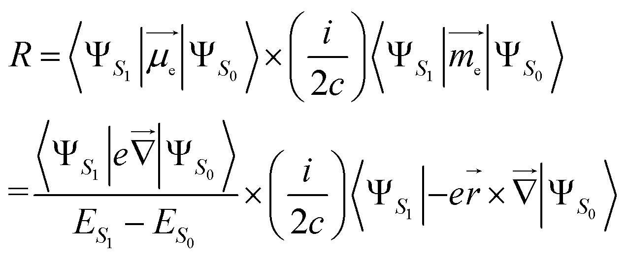
Here, we investigate four types of representative organic chiral emitters, most of which contain an electron-donor segment and an electron-acceptor segment (see chemical structures in Fig. 1a); they are distinguished by their origin of chirality: planar chirality,18 central chirality,19,20 helical chirality,10,21,22 and axial chirality.11,23,24 Our findings reveal that the distribution of transition density plays a vital role in these chromophores, which can be categorized into two model classes (Model-I and Model-II, Fig. 1b). In Model-I, the transition density is spread across the entire chromophore, and the CPL properties can be controlled through inter-segment twisting. Conversely, in Model-II, the transition density is primarily localized on either the donor (D) or acceptor (A) moiety, and twisting has no impact on the CPL properties. Instead, conformational disorders due to molecular vibrations can reduce the g-factor. Our results demonstrate that the molecular design of large g-factor emitters must satisfy two requirements: extended delocalization of transition density and restriction of chromophore inter-segment twisting at an optimal angle. This understanding can be extended to new chiroptical materials and systems, which would motivate further studies in the CPL field.
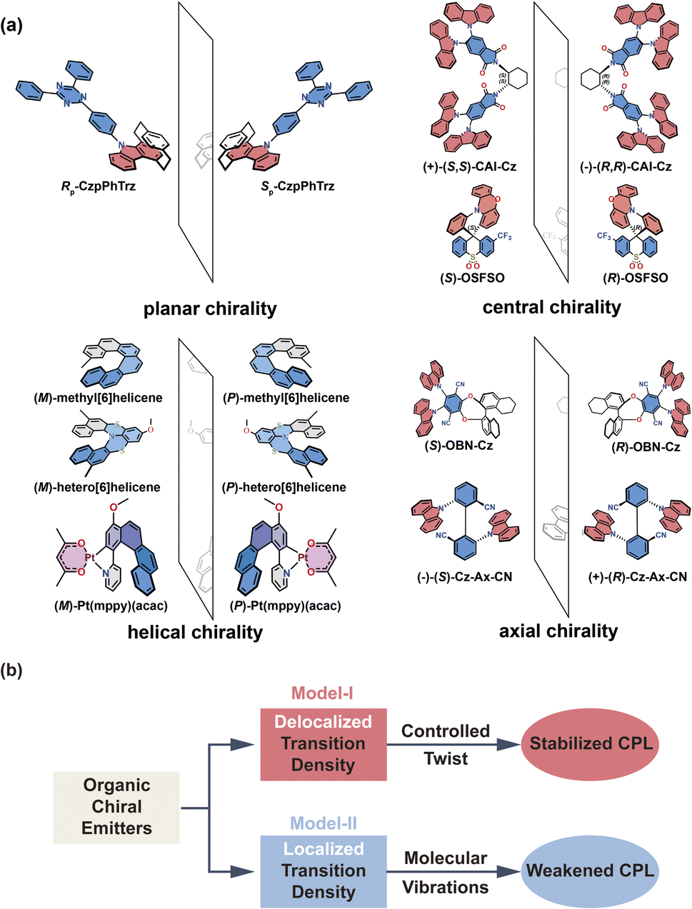 | ||
| Fig. 1 (a) Chemical structures of representative organic chiral emitters explored in this study. Planar chirality (no stereogenic center, but two non-coplanar rings that are each dissymmetric); central chirality (presence of a stereogenic center); helical chirality (no stereogenic center, but presence of a helix), and axial chirality (no stereogenic center, but axis of chirality). The D (A) molecular fragments are colored in red (blue). (b) Illustration of the role of transition density in the research of CPL properties. | ||
Results and discussion
Background of theoretical models
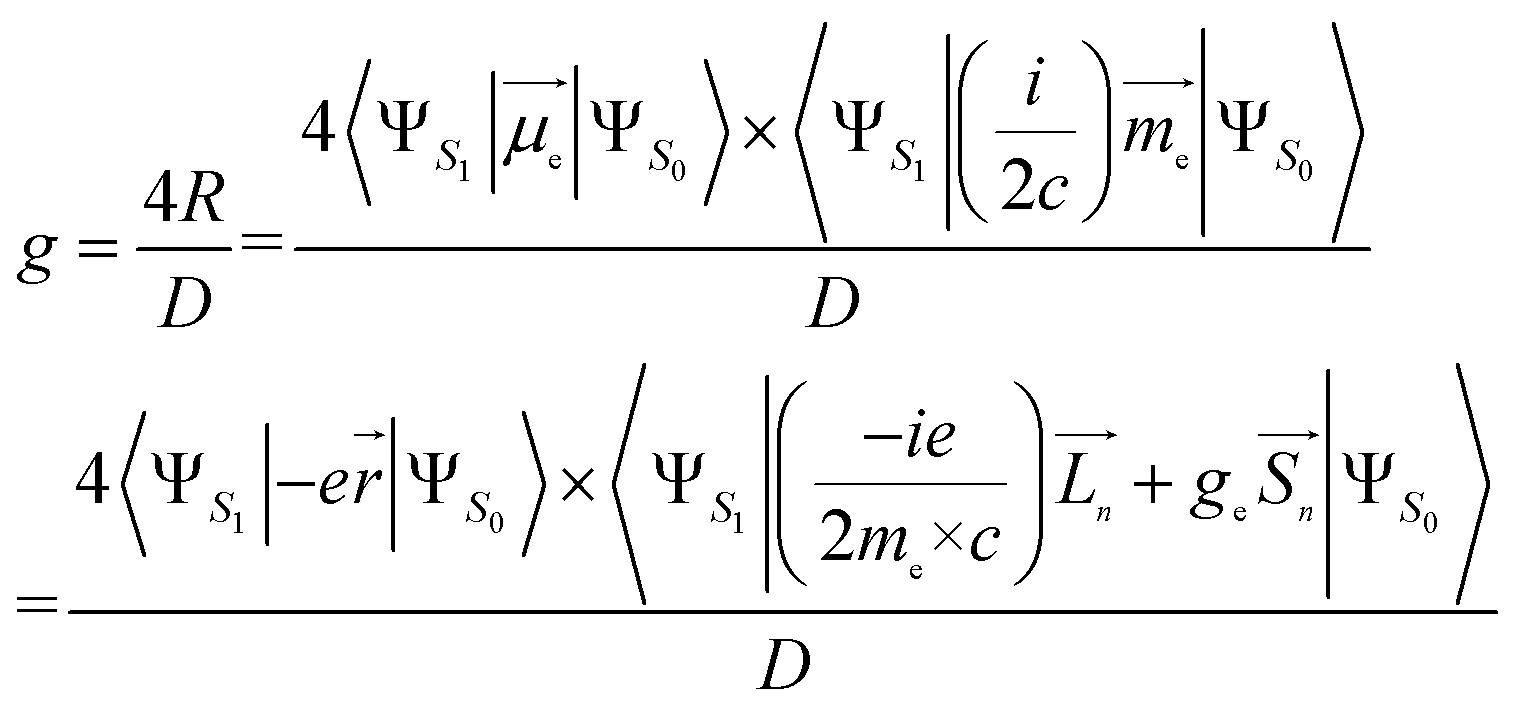
In an electronic S1 → S0 transition, the rotatory strength R theoretically corresponds to the experimental CPL intensity. There are two expressions for the R:25–27(i) Velocity form, which is origin-invariant and independent from the completeness of the basis set, is given by:
 | (1) |
(ii) Length form, which is origin-dependent in calculations with incomplete basis set, is given by:
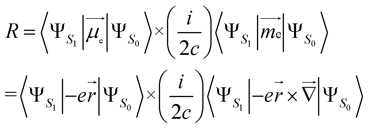 | (2) |
 is the electric dipole transition moment (EDTM) for the S1 → S0 transition;28
 the magnetic dipole transition moment (MDTM) for the S1 → S0 transition;29e, the elementary charge of an electron;
 ![[r with combining right harpoon above (vector)]](https://www.rsc.org/images/entities/char_0072_20d1.gif) , the position operator;
, the position operator; ![[capital Delta, Greek, vector]](https://www.rsc.org/images/entities/char_e13c.gif) , the curl operator; c, the speed of light, with c−1 approximately equal to 1/137 atomic units (a.u.).30 The calculated R-value is commonly reported in cgs units of 10−40 esu2 cm2. A unit conversion factor of 1 a.u. = 2.541746 × 10⁻¹⁸ esu cm is commonly used, as explained in ref. 31. To ensure a precise assessment of the molecular coordinate system and its impact on CPL properties, we carefully select the CAM-B3LYP functional as our preferred method and primarily focus on the length form of the R-value in the remainder of the discussion.
, the curl operator; c, the speed of light, with c−1 approximately equal to 1/137 atomic units (a.u.).30 The calculated R-value is commonly reported in cgs units of 10−40 esu2 cm2. A unit conversion factor of 1 a.u. = 2.541746 × 10⁻¹⁸ esu cm is commonly used, as explained in ref. 31. To ensure a precise assessment of the molecular coordinate system and its impact on CPL properties, we carefully select the CAM-B3LYP functional as our preferred method and primarily focus on the length form of the R-value in the remainder of the discussion.
Using the length form of the R-value, the g-factor, a critical parameter that provides a quantitative evaluation of the CPL magnitude, can be estimated as follows:32–35
 | (3) |
Here, me is the mass of the electron; ge ≃ 2, the free electron g-factor; ![[L with combining right harpoon above (vector)]](https://www.rsc.org/images/entities/i_char_004c_20d1.gif) , orbital angular momentum;
, orbital angular momentum; ![[S with combining right harpoon above (vector)]](https://www.rsc.org/images/entities/i_char_0053_20d1.gif) , spin angular momentum; n is the components of the Cartesian coordinate system; D, dipole strength, can be approximated as the squared values of EDTM for dipole-allowed transitions.36 However, for transitions with very small dipole strength, D must be expanded to also incorporate the squared values of MDTM and the electric quadrupole transition moment.37
, spin angular momentum; n is the components of the Cartesian coordinate system; D, dipole strength, can be approximated as the squared values of EDTM for dipole-allowed transitions.36 However, for transitions with very small dipole strength, D must be expanded to also incorporate the squared values of MDTM and the electric quadrupole transition moment.37
It is worth reiterating that eqn (3) considers the orbital contribution  to the MDTM. This parameter
  is intimately linked to rotating and overlapping between the transition orbitals, which in turn affects the EDTM and, ultimately, the calculated R and g values. To gain deeper insights into the impact of transition orbital changes on CPL properties, we utilized both the torsion angle Boltzmann distribution method and the nuclear ensemble approach38–40 in our investigation. It is worth noting that these two methods share a common feature: they both describe the dynamic characteristics of excited states by generating a set of nuclear coordinates. However, the torsion angle Boltzmann distribution method and the nuclear ensemble approach differ in how they generate these nuclear coordinates and how each nuclear coordinate contributes to the CPL properties (i.e., the calculated R and g values). The torsion angle Boltzmann distribution method generates nuclear coordinates with a uniform distribution, where the contribution of each coordinate to the CPL properties is determined by the corresponding Boltzmann vibrational energy distribution. In contrast, the nuclear ensemble approach generates nuclear coordinates based on a harmonic Wigner distribution, where each coordinate contributes equally to the CPL properties. This means that the results calculated through the nuclear ensemble approach are primarily arithmetic averages (see ESI† for more details). Additionally, the torsion angle Boltzmann distribution method focuses solely on inter-segment twisting between fragments (Fig. 2b), while the nuclear ensemble approach considers all molecular vibrations modes, including stretching, scissoring, rocking, and wagging (Fig. 2c).
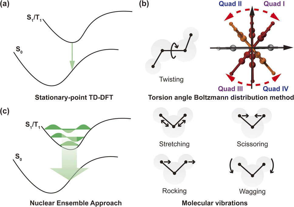 | ||
| Fig. 2 (a) Schematic diagram of stationary-point TD-DFT approach. (b) Schematic diagram of twisting and torsion angle Boltzmann distribution method. (c) Schematic diagram of nuclear ensemble approach and different molecular vibrations (stretching, scissoring, rocking and wagging). | ||
It is also informative to note that the torsion angle Boltzmann distribution method and the nuclear ensemble approach are computationally more demanding than the stationary-point time-dependent density functional theory (TD-DFT) calculation (Fig. 2a). The computational time required depends on the number of samples (i.e., nuclear coordinates), which can be determined by the magnitude of fluctuations in the sign of the R and g values caused by molecular vibrations. The larger the fluctuations, the greater the number of samples needed to accurately calculate the R and g values, thereby increasing the computation time. To strike a balance between computation time and result accuracy, we collected 1000 samples for each molecule under investigation, resulting in the required computation time 1000 times longer than that of the stationary-point TD-DFT calculation. Nonetheless, parallel computing of these samples during the actual computation process can reduce overall computation time, subject to the available computing resources.
Construction of theoretical models
In order to discuss more clearly, we start by considering two models with dipole-allowed transitions through two molecules: molecule 1 (Fig. 3a) and molecule 2 (Fig. 3d), which are both D–π–A structures containing pyrrole (D), phenylene bridge, and cyano (A) moieties in para positions. The only structural difference between the two molecules is that the pyrrole ring of 1 is connected to the phenylene bridge through an α-carbon (C), while the pyrrole ring of 2 is connected through its nitrogen (N).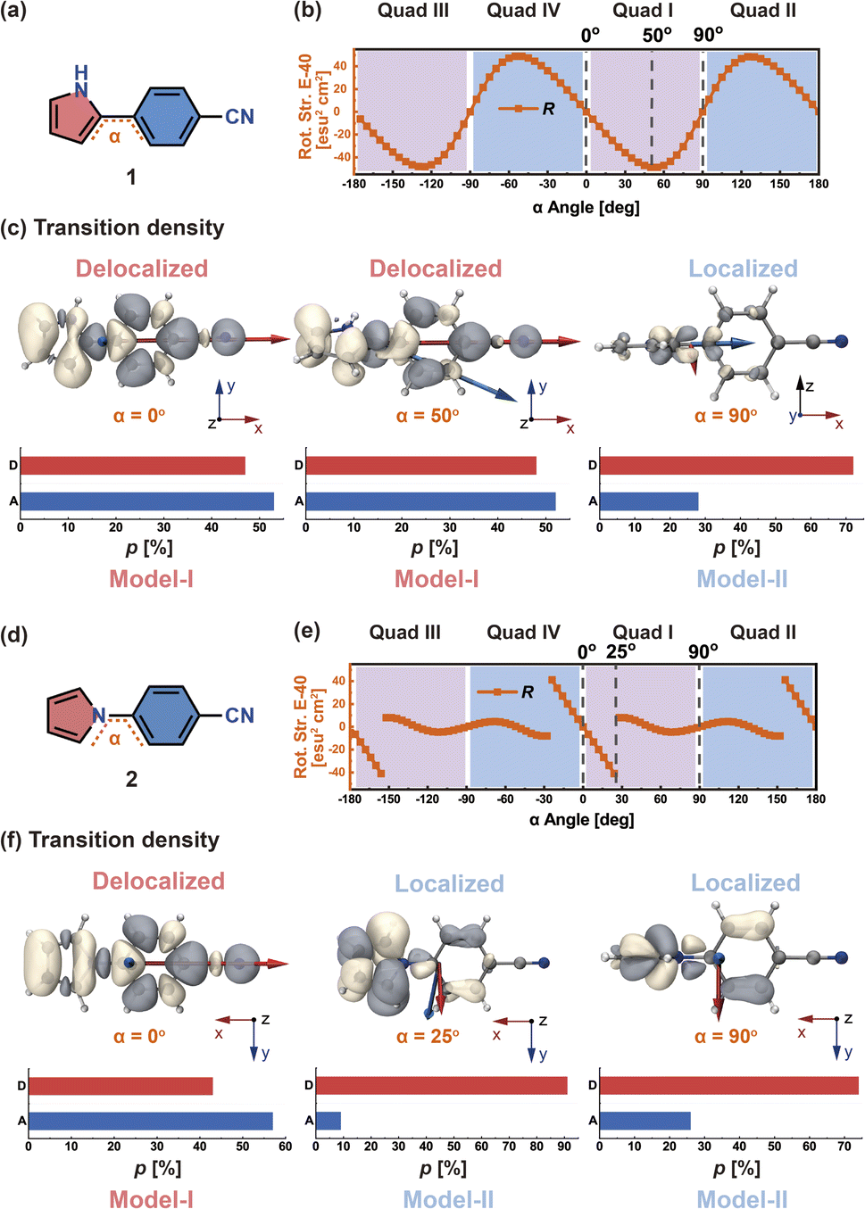 | ||
| Fig. 3 (a) Chemical structure of 1. Angle α is the twist angle between the phenylene ring and the pyrrole moiety. (b) Rotatory strength (orange, in units of E-40 esu2 cm2) as a function of α (in units of deg). (c) S1 → S0 transition density distributions and proportions (p, in units of %), when α = 0°, 50°, and 90°; the red (blue) arrow indicates the EDTM (MDTM) vector. (d) Chemical structure of 2. (e) Rotatory strength (orange, in units of E-40 esu2 cm2) as a function of α (in units of deg). (f) S1 → S0 transition density distributions and p (in units of %), when α = 0°, 25°, and 90°. | ||
The dihedral angle α between the pyrrole and phenylene moieties is rotated around the single bond with a step size of 5° from −180° to 180°, which leads to 72 structures for which the S1 geometry is optimized. Then, TD-DFT calculations were performed on these structures (see Fig. S1†). The α dihedral angles can be divided into four quadrants; here, we select quadrant I for the following discussion. We define the proportion of transition density distribution on D and A as pD and pA, respectively.
In molecule 1 (Fig. 3a), the S1 → S0 transition density is delocalized over the D and A moieties (pD = 47%, pA = 53%, Fig. 3c), except for the α = 90° structure. When α = 0°, the pyrrole ring (D) is fully conjugated with the benzonitrile moiety (A). The α = 0° structure of 1 is where the largest EDTM and smallest MDTM are observed (Fig. S1†). We note that the EDTM corresponds to electron displacement within the conjugation plane along the x-axis, while the MDTM corresponds to the rotation and motion of electrons in the xy plane around the z-axis (Fig. 3c). As a result, the E–M angle (θE,M, the angle between EDTM and MDTM) is equal to 90° and thus R and g are both zero (Fig. S1†). When α increases, the reduction in conjugation leads to a decrease in EDTM. Part of the conjugation plane is now rotated around the x-axis; thus, π electrons will rotate around the x-axis upon the transition, resulting in a change in the orbital angular momentum and a gradual increase in the x component of MDTM 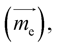 as well as causing a deviation of θE,M from orthogonality (θE,M ≠ 90°). Therefore, the (absolute) R-value increases with α and the largest R-value is obtained at α = 50° (Fig. 3b). A further increase in α (50° < α < 90°) leads to a reduction in the (absolute) R-value due to the decreased EDTM
 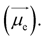 On the other hand, g increases gradually and experiences a rapid surge when α is greater than 50° since g is proportional to
  (Fig. S1†).
In molecule 2 (Fig. 3d), since the pyrrole HOMO has a node on the N atom, the transition density does not delocalize over the whole π system at large α values. When α is in the range from 0° to 25°, the transition density still delocalizes between D and A (pD = 43%, pA = 57%, Fig. 3f); therefore, here, R gradually increases with α from 0° to 25°. In contrast, when α is greater than 25°, the transition density mainly distributes on D (pD = 74–91%); this localization prevents any changes in the orbital angular momentum due to the D–A twisting, and leads to EDTM and MDTM vectors no longer aligned with the x-axis (which is the direction of D–A conjugation). The corresponding R is no longer controlled by the D–A twisting and abruptly decreases when α reaches 25° (Fig. 3e).
In view of the aforementioned phenomenon, we emphasize that it is the different transition density distributions that lead to the different variations of the CPL properties of molecules 1 and 2 as a function of the dihedral angle. According to the above analysis of the S1 → S0 transition density (Fig. 3c and f), we find when the pD and pA values are both close to 50% (transition density delocalization), the CPL can be controlled in a stable and effective manner by the chromophore twist angle between the D and A moieties. We define this situation as Model-I. In contrast, if the pD or pA value is significantly larger than the other one (transition density localization), the chromophore twisting cannot control the CPL. It can be anticipated that the conformational disorder induced by molecular vibrations can cause a loss of CPL. We define such systems as Model-II. Accordingly, organic chiral emitters can be classified as Model-I or Model-II based on the transition density delocalization or localization, respectively.
Transition density delocalization
Based on the above understanding, we focus on the pivotal role of transition density, as well as the impact of chromophore twisting and molecular vibrations for the CPL of representative organic chiral emitters, via the torsion angle Boltzmann distribution method and the nuclear ensemble approach, respectively. We first investigated one of the Model-I examples, namely Rp-CzpPhTrz (Fig. 4a), whose transition density is delocalized over the D and A moieties (pD = 47%, pA = 53%, Fig. S2†). This chiral molecule is based on chiral D (indolo[2.2]paracyclophane) and achiral A (2,4,6-triphenyl-1,3,5-triazine) segments. Cyclophane, a chiral scaffold, controls the D–A twist angle (α) of Rp-CzpPhTrz in the range 58–74° corresponding to quadrant I (Fig. 4b) at room temperature. As shown in Fig. 4c, the resulting R has a narrow distribution, in the range of −4.5 × 10−39 to −4.9 × 10−39 esu2 cm2, turning into a high average![[R with combining macron]](https://www.rsc.org/images/entities/i_char_0052_0304.gif) (−4.8 × 10−39 esu2 cm2), which is close to the ensemble-averaged value (−4.5 × 10−39 esu2 cm2) from the nuclear ensemble approach (Fig. S3†). These results show that the CPL properties of Rp-CzpPhTrz are well controlled by this restricted D–A twisting. For the sake of comparison, the CPL properties of the chiral molecule Rp-CzpEtPhTrz (Fig. 4d) without restricted torsion were also calculated via the torsion-angle Boltzmann distribution method. To increase the D–A distance and minimize steric repulsion, an acetylene linkage was incorporated between the D and A segments. As seen from the calculated potential energy surface (Fig. 4e and S4†), Rp-CzpEtPhTrz displays very flexible D–A torsion from −180° to 180° in all four quadrants, resulting in a lower value of 1.9 × 10−39 esu2 cm2 which is opposite in sign (see Fig. 4f). These results underpin the importance of controlling the D–A twisting within one quadrant for organic chiral emitters with delocalized transition density in order to generate a strong CPL intensity.
(−4.8 × 10−39 esu2 cm2), which is close to the ensemble-averaged value (−4.5 × 10−39 esu2 cm2) from the nuclear ensemble approach (Fig. S3†). These results show that the CPL properties of Rp-CzpPhTrz are well controlled by this restricted D–A twisting. For the sake of comparison, the CPL properties of the chiral molecule Rp-CzpEtPhTrz (Fig. 4d) without restricted torsion were also calculated via the torsion-angle Boltzmann distribution method. To increase the D–A distance and minimize steric repulsion, an acetylene linkage was incorporated between the D and A segments. As seen from the calculated potential energy surface (Fig. 4e and S4†), Rp-CzpEtPhTrz displays very flexible D–A torsion from −180° to 180° in all four quadrants, resulting in a lower value of 1.9 × 10−39 esu2 cm2 which is opposite in sign (see Fig. 4f). These results underpin the importance of controlling the D–A twisting within one quadrant for organic chiral emitters with delocalized transition density in order to generate a strong CPL intensity.
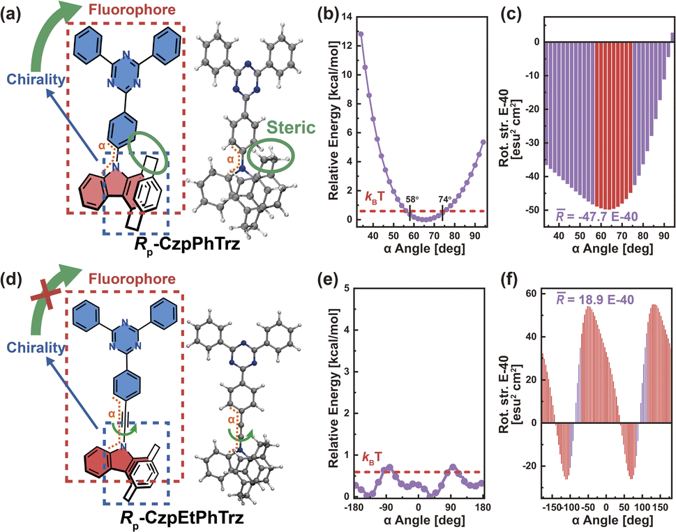 | ||
| Fig. 4 (a) Chemical structure and optimized S1-state structure of Rp-CzpPhTrz. (b) Potential energy surface (in units of kcal mol−1) and (c) rotatory strength (in units of E-40 esu2 cm2) as a function of dihedral angle α (in units of deg) between the D–A planes of Rp-CzpPhTrz in the optimized S1 state. (d) Chemical structure and optimized S1-state structure of Rp-CzpEtPhTrz. (e) Potential energy surface (in units of kcal mol−1) and (f) rotatory strength (in units of E-40 esu2 cm2) as a function of dihedral angle α (in units of deg) between the D–A planes of Rp-CzpEtPhTrz in the optimized S1 state. The red line in (b) and (e) represents kBT at 298 K (0.6 kcal mol−1), where kB is the Boltzmann constant and T is the temperature (in units of K). | ||
To validate this argument, we further investigated the other two Model-I examples. In the case of phthalimide (A)–carbazoles (D), namely (−)-(R,R)-CAI-Cz (Fig. 5a), the chiral 1,2-diaminocyclohexane scaffold controls the D–A twist at around 65°. Due to the steric hindrance coming from the multiple adjacent carbazoles, the D–A twist remains well restricted within quadrant I. The energy difference for the D–A twist of (−)-(R,R)-CAI-Cz from 65° to 90° was calculated to be 198.1 kcal mol−1 (Fig. 5b). Additionally, the transition density in (−)-(R,R)-CAI-Cz is delocalized over the D and A moieties (pD = pA = 50%, Fig. S5†), suggesting that this system falls into the Model-I category and the CPL can be controlled in a stable way via the restrictions in D–A twisting. The resulting R and g distributions generated by the nuclear ensemble approach are shown in Fig. 5c and d, respectively. Compared with those from stationary-point TD-DFT (Table 1), the ensemble-averaged (1.5 × 10−39 esu2 cm2, Fig. 5c) and ḡ (3.3 × 10⁻³, Fig. 5d) values are slightly reduced (by some 10%). In contrast, in the case of the (R)-OBN-Cz molecule based on phthalonitrile (A)–carbazole (D) moieties (Fig. 5e), although the transition density is also delocalized over the D and A segments (pD = 43%, pA = 52%, Fig. S6†), D–A twisting to cross 90° from 65° (quadrant I) to 105° (quadrant II) is easy, as it is characterized by an energy barrier of 3.4 kcal mol−1 and an energy difference of 0.4 kcal mol−1, as shown in Fig. 5f. Therefore, in the nuclear ensemble approach, the resulting (−5.0 × 10−40 esu2 cm2, Fig. 5g) and ḡ (−4.6 × 10⁻⁴, Fig. 5h) values in (R)-OBN-Cz reduce severely by some 30% compared to those from stationary-point TD-DFT (Table 1). All of these observations support our proposition that the control of the D–A twisting within one quadrant while without crossing the quadrant boundary (0°, 90°, 180° or 270°) is essential to ensure the CPL property of organic chiral emitters with delocalized transition density.
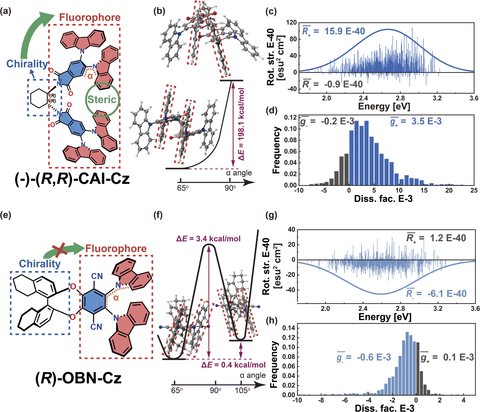 | ||
| Fig. 5 (a) Chemical structure of (−)-(R,R)-CAI-Cz. (b) Calculated energetics (in units of kcal mol−1) of the D–A twisting process of (−)-(R,R)-CAI-Cz. (c) Rotatory strength (in units of E-40 esu2 cm2) and simulated CPL spectra based on nuclear ensembles of (−)-(R,R)-CAI-Cz. (d) Histogram of g-factor (in units of E-3) of (−)-(R,R)-CAI-Cz (bottom panel). (e) Chemical structure of (R)-OBN-Cz. (f) Calculated energetics (in units of kcal mol−1) of the D–A twisting process of (R)-OBN-Cz. (g) Rotatory strength (in units of E-40 esu2 cm2) and simulated CPL spectra based on nuclear ensembles of (R)-OBN-Cz. (h) Histogram of g-factor (in units of E-3) of (R)-OBN-Cz. | ||
| Molecule | f | θ E,M | R | g |
![[f with combining macron]](https://www.rsc.org/images/entities/i_char_0066_0304.gif)
|
![[small theta, Greek, macron]](https://www.rsc.org/images/entities/i_char_e0c9.gif) E,M
E,M
|
|
ḡ | g PL |
|---|---|---|---|---|---|---|---|---|---|
|
a Oscillator strengths (f), angles (θE,M) between the electric and magnetic transition dipole moments (in units of deg), rotatory strengths (R, in units of esu2 cm2), and g-factors calculated from stationary-point TD-DFT calculations.
b Oscillator strengths (), angles (E,M) between the electric and magnetic transition dipole moments (in units of deg), rotatory strengths (, in units of esu2 cm2), and g-factors (ḡ) calculated from the nuclear ensemble approach.
c Experimental photoluminescence dissymmetry factors (gPL) in dilute solutions and partially in thin films.
|
|||||||||
| R p-CzpPhTrz | 3.0 × 10⁻¹ | 103 | −5.0 × 10−39 | −8.5 × 10⁻⁴ | 2.7 × 10⁻¹ | 106 | −4.5 × 10−39 | −8.1 × 10⁻⁴ | −1.2 × 10⁻³ |
| (−)-(R,R)-CAI-Cz | 2.0 × 10⁻² | 56 | 1.7 × 10−39 | 3.7 × 10⁻³ | 1.8 × 10⁻² | 66 | 1.5 × 10−39 | 3.3 × 10⁻³ | 1.1 × 10⁻³ |
| (R)-OBN-Cz | 4.8 × 10⁻² | 173 | −7.6 × 10−40 | −6.6 × 10⁻⁴ | 4.3 × 10⁻² | 110 | −5.0 × 10−40 | −4.6 × 10⁻⁴ | −4.6 × 10⁻⁴ |
| (P)-Pt(mppy)(acac) | 4.1 × 10⁻⁶ | 86 | 1.2 × 10−42 | 1.1 × 10⁻³ | 4.0 × 10⁻⁶ | 82 | 2.2 × 10−42 | 5.0 × 10⁻³ | 1.2 × 10⁻² |
| (P)-Hetero[6]helicene | 4.5 × 10⁻² | 116 | −1.1 × 10−38 | −1.0 × 10⁻² | 4.7 × 10⁻² | 114 | −1.0 × 10−38 | −7.7 × 10⁻³ | −9.0 × 10⁻³ |
| (P)-Methyl[6]helicene | 1.8 × 10⁻³ | 100 | −8.5 × 10−41 | −2.4 × 10⁻³ | 1.7 × 10⁻² | 94 | −4.8 × 10−40 | −5.6 × 10⁻⁵ | −5.0 × 10⁻⁵ |
| Iso-(R)-OBN-CzB1 | 1.9 × 10⁻² | 68 | 1.1 × 10−39 | 2.7 × 10⁻³ | 2.5 × 10⁻² | 71 | 6.9 × 10−40 | 1.5 × 10⁻³ | 2.1 × 10⁻³ |
| Iso-(R)-OBN-CzC1 | 3.3 × 10⁻² | 89 | 7.5 × 10−41 | 1.1 × 10⁻⁴ | 2.8 × 10⁻² | 88 | 5.3 × 10−42 | 3.8 × 10⁻⁵ | 1.0 × 10⁻⁴ |
| (+)-(R)-Cz-Ax-CN | 6.4 × 10⁻³ | 65 | 1.6 × 10−39 | 1.2 × 10⁻² | 1.1 × 10⁻² | 75 | 7.8 × 10−40 | 3.4 × 10⁻³ | 5.2 × 10⁻³ |
| (R)-OSFSO | 6.6 × 10⁻³ | 97 | −7.1 × 10−40 | −5.3 × 10⁻³ | 6.2 × 10⁻³ | 100 | −4.0 × 10−40 | −1.2 × 10⁻³ | −1.6 × 10⁻³ |
Helical chirality is an intrinsic feature of the helicenes, which are constructed from ortho-fused aromatic rings; theoretically, the transition density can be delocalized over the whole polycyclic aromatic system, belonging to Model-I. Thus, the resulting R and g distributions of (P)-Pt(mppy)(acac) and (P)-hetero[6]helicene generated by the nuclear ensemble approach are more stable due to the effective twisting control of the [6]helicene structure (Fig. 6b and d). Interestingly, although based on the same [6]helicene structure, the R and g distributions of (P)-methyl[6]helicene are very unstable (Fig. 6f). The ḡ value in the nuclear ensemble approach reduces severely (by some 97%), in comparison to stationary-point TD-DFT (Table 1). Note that the calculated ḡ value based on the nuclear ensemble approach (−5.6 × 10⁻⁵) is consistent with the experimental g-value (−5.0 × 10⁻⁵). Analyzing some conformations generated by the nuclear ensemble approach, it can be seen that the distance between the two extremities of (P)-methyl[6]helicene is so close (4.1 Å) that the transition density can distribute locally in the space between the extremities after considering molecular vibrations (Fig. S7–S9†). These observations suggest that the transition density should be delocalized over the entire molecule during vibrations, thereby ensuring the CPL property of organic chiral emitters with delocalized transition density.
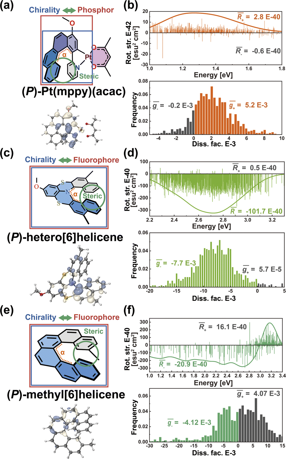 | ||
| Fig. 6 (a) Chemical structure and T1 → S0 transition density distribution of (P)-Pt(mppy)(acac). (b) Rotatory strength (in units of E-40 esu2 cm2), simulated CPL spectra and histogram of g-factor (in units of E-3) based on nuclear ensembles of (P)-Pt(mppy)(acac). (c) Chemical structure and S1 → S0 transition density distribution of (P)-hetero[6]helicene. (d) Rotatory strength (in units of E-40 esu2 cm2), simulated CPL spectra and histogram of g-factor (in units of E-3) based on nuclear ensembles of (P)-hetero[6]helicene. (e) Chemical structure and S1 → S0 transition density distribution of (P)-methyl[6]helicene. (f) Rotatory strength (in units of E-40 esu2 cm2), simulated CPL spectra, and histogram of g-factor (in units of E-3) based on nuclear ensembles of (P)-methyl[6]helicene. | ||
Transition density localization
As we described above, organic chiral emitters whose transition density is mainly distributed on a single (D or A) moiety can be classified as Model-II. For the sake of comparison, we designed an isomer of (R)-OBN-Cz, iso-(R)-OBN-CzB1, see Fig. 7a. Compared with (R)-OBN-Cz, where the transition density is delocalized over the D and A segments, iso-(R)-OBN-CzB1 exhibits transition density distributions mainly localized on phthalonitrile (A) with little extension to one of the carbazoles (D) (pD = 35%, pA = 61%, Fig. 7b and S14–S16†), which confirms it belongs to Model-II, as we anticipated. Due to the steric hindrance related to the proximity between D and the chiral unit, the D–A twist of iso-(R)-OBN-CzB1 can be well confined within quadrant I (Fig. S17†). However, we find that the (6.9 × 10−40 esu2 cm2, Fig. 7c) and ḡ (1.5 × 10⁻³, Fig. 7d) values based on the nuclear ensemble approach are both reduced by some 40% compared to those from the stationary-point calculation (Table 1). In the iso-(R)-OBN-CzB1 ensemble (1000 molecular geometries), nearly 30% (293 molecular geometries, Fig. 7c) of the conformations display CPL with a negative sign, (−)-CPL, leading to the decrease in g-factor ( = −0.6 × 10⁻³, Fig. 7d). Intriguingly, for another designed isomer iso-(R)-OBN-CzC1 (Fig. 7e), due to more localized transition density (pD = 32%, pA = 68%, Fig. 7f and S18–S20†), it is observed that both R and g exhibit diminished values, with the ensemble-averaged (5.3 × 10−42 esu2 cm2, Fig. 7g) and ḡ (3.8 × 10⁻⁵, Fig. 7h) values that are reduced by some 93% and 65%, respectively, in comparison to stationary-point TD-DFT (Table 1). Similarly, in the case of (+)-(R)-Cz-Ax-CN (Fig. 7i), the transition density is mainly localized on the biphenyl segment (pD = 24%, pA = 76%, Fig. 7j and S21–S23†), which is also akin to Model-II. In comparison with the values coming from stationary-point TD-DFT (Table 1), the ensemble-averaged (7.8 × 10−40 esu2 cm2, Fig. 7k) and ḡ (3.4 × 10⁻³, Fig. 7l) values show 50% and 70% reduction, respectively. There are 287 molecular geometries (also nearly 30% in the ensemble, Fig. 7k) showing (−)-CPL with
  value of −1.5 × 10⁻³ (Fig. 7l). These observations suggest that when there is no effective control over the CPL coming from restricted D–A twisting, the conformational disorder generated by molecular vibrations can easily result in the loss of the corresponding CPL signal.
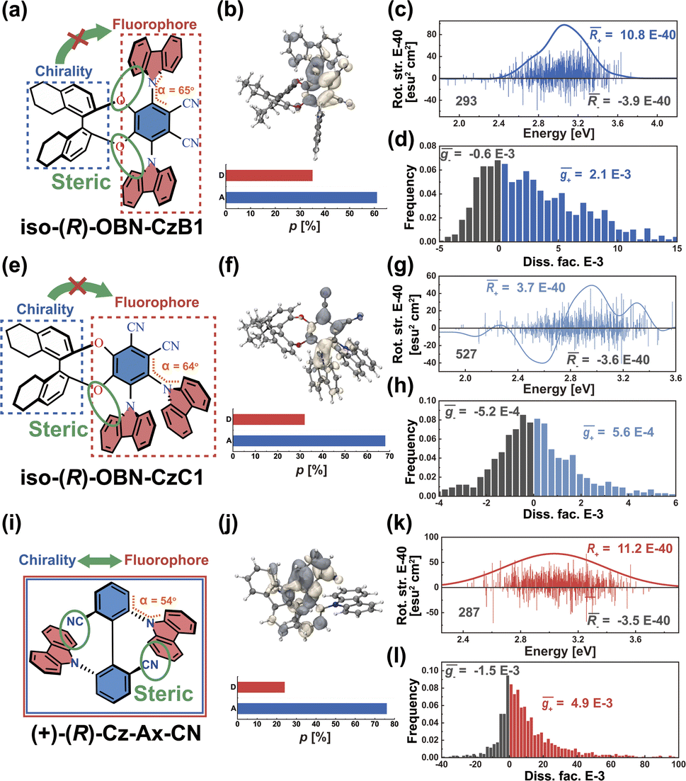 | ||
| Fig. 7 (a) Chemical structure of engineered molecule iso-(R)-OBN-CzB1. (b) S1 → S0 transition density distribution and proportions (p, in units of %) of iso-(R)-OBN-CzB1. (c) Rotatory strength (in units of E-40 esu2 cm2) and simulated CPL spectra based on nuclear ensembles of iso-(R)-OBN-CzB1. (d) Histogram of g-factor (in units of E-3) of iso-(R)-OBN-CzB1. (e) Chemical structure of engineered molecule iso-(R)-OBN-CzC1. (f) S1 → S0 transition density distribution and proportions (p, in units of %) of iso-(R)-OBN-CzC1. (g) Rotatory strength (in units of E-40 esu2 cm2) and simulated CPL spectra based on nuclear ensembles of iso-(R)-OBN-CzC1. (h) Histogram of g-factor (in units of E-3) of iso-(R)-OBN-CzC1. (i) Chemical structure of (+)-(R)-Cz-Ax-CN. (j) S1 → S0 transition density distribution and p (in units of %) of (+)-(R)-Cz-Ax-CN. (k) Rotatory strength (in units of E-40 esu2 cm2) and simulated CPL spectra based on nuclear ensembles of (+)-(R)-Cz-Ax-CN. (l) Histogram of g-factor (in units of E-3) of (+)-(R)-Cz-Ax-CN. | ||
To further support this proposition, we calculated another Model-II example where there is no D–A twisting freedom due to the presence of a rigid spiro skeleton, (R)-OSFSO (Fig. 8a). In this molecule, the transition density is mainly localized on the D segment (pD = 75%, pA = 25%, Fig. 8b and S24†). In the nuclear ensemble approach, the (−4.0 × 10−40 esu2 cm2, Fig. 8c) and ḡ (−1.2 × 10⁻³, Fig. 8d) values reduce by 40% and 80%, respectively, in comparison to stationary-point TD-DFT (Table 1). In the ensemble (1000 molecular geometries) of (R)-OSFSO, nearly 25% (246 molecular geometries, Fig. 8c) of the conformations exhibit CPL with a positive sign, (+)-CPL, with a 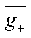 value of 0.6 × 10⁻³ (Fig. 8d). To unveil the potential conformations that lead to the loss of CPL, we calculated the four possible transition states (TS 1 to 4) and four possible conformations (RMΔ, RPΔ, RMΛ, and RPΛ) of (R)-OSFSO.41 These four possible conformations can be kinetically accessed from each other, as illustrated in Fig. 8e. However, the calculations indicate that the RMΔ and RMΛ conformations of (R)-OSFSO, which have opposite signs of R-values (Fig. S25†), are thermodynamically preferred following a rocking vibration of the S
![[double bond, length as m-dash]](https://www.rsc.org/images/entities/char_e001.gif) O bonds, demonstrating the contribution of molecular vibrations to the CPL loss.
O bonds, demonstrating the contribution of molecular vibrations to the CPL loss.
 | ||
| Fig. 8 (a) Chemical structure of (R)-OSFSO. (b) S1 → S0 transition density distribution and proportions (p, in units of %) of (R)-OSFSO. (c) Rotatory strength (in units of E-40 esu2 cm2) and simulated CPL spectra based on nuclear ensembles of (R)-OSFSO. (d) Histogram of g-factor (in units of E-3) of (R)-OSFSO. (e) Calculated energetics of four possible transition states (TS 1 to 4) and four possible conformations (RMΔ, RPΔ, RMΛ, and RPΛ) of (R)-OSFSO. | ||
In light of the above results, it is imperative to discuss how to effectively enhance the g-factor for chiroptical materials. According to the calculated results based on the nuclear ensemble approach (Table 1), the g-factor (−7.7 × 10⁻³) of (P)-hetero[6]helicene is the largest. To elucidate further the origin of this large g-factor, we designed four other molecules (labeled 3–6 in Fig. 9a) based on (P)-hetero[6]helicene. Undoubtedly, the twisting angle of these molecules is stably and effectively controlled around the optimal value of ∼50° by the S-doped [6]helicene structure. However, there is an exponential difference in the g-factor between these molecules: the calculated (absolute) g-factor increases from 3.9 × 10⁻⁴ in 3 up to ∼0.1 in 6. Close inspection of the transition densities (Fig. 9b) exhibits an increasing spread as the molecules become more conjugated and/or delocalized. This effect can be quantitatively assessed by computing the transition density delocalization volume. Fig. 9c shows strong linear exponential correlations (coefficient of determination, R2 = 0.99) between the calculated (absolute) g-factor and the transition density delocalization volume, with the more extended transition density providing, the g-factor increases exponentially. Inspired by this finding, we took a closer look at the transition density of two representative chiral polymers (Fig. S26†).42,43 The experimental (absolute) g-factor (0.16) of chiral polymer with delocalized transition density is significantly larger than that with localized transition density (9.7 × 10⁻³), which confirms the trend observed in Fig. 9c. Therefore, the enhancement of the g-factor could be intentionally realized through the extended delocalization of the transition density across the molecular structure of conjugated systems.
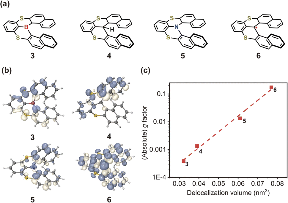 | ||
| Fig. 9 (a) Chemical structures and (b) transition densities of engineered molecules 3–6. (c) Calculated (absolute) g-factor as a function of transition density delocalization volume for 3–6. | ||
Conclusions
In summary, we have uncovered the pivotal role of transition density in the circularly polarized luminescence (CPL) of organic chiral emitters. To design CPL materials with large and stable g values (that is less susceptible to molecular vibrations), it is necessary to implement two control factors: (i) the transition density (between the electronic states involved in the emission) should be delocalized across the entire chromophore; and (ii) the chromophore inter-segment twisting should be restricted and tuned to an optimal value (∼50°). When the transition density is localized on a single segment (D or A or connecting bridge or space), the conformational disorder induced by molecular vibrations can lead to a significant loss in CPL. By providing an in-depth understanding at the molecular level, our results can not only stimulate the development of a new generation of organic chiral emitters (e.g., helicene radicals with spin delocalization and 100% internal quantum efficiency maximum), but can also be extended to polymers or supramolecular assemblies, opening up the exciting possibility to the future exploitation of CP-OLEDs with high efficiency and high g-factor simultaneously.We have also shown in this work that the nuclear ensemble approach can be a useful tool for the prediction of the g-factor in an organic chiral emitter at the molecular level. The method is generally applicable to account for the effect of vibration-induced conformational disorder in a molecule and can match the experimental data collected in dilute solutions and at least qualitatively in films (Table S1†). We note, however, that some of the molecular vibrations can be affected by solvent viscosity and solid-state effects in a host matrix, which may, in turn, impact the corresponding CPL properties. Thus, follow-up studies should investigate the impact of solvent–solute interactions and host–guest interactions13 on CPL, keeping in sight the explicit target of maximizing the g factors.
Finally, it is important to note that the spin contribution to the MDTM also plays a critical role in the CPL process. For instance, the ensemble-averaged g-factor of phosphor (P)–Pt(mppy)(acac) with spin-1 and spin–orbit coupling37 was found to be ∼3.5 times larger than that of stationary-point TD-DFT calculation, while the g-factor of helicene radical 6 with spin-1/2 was calculated to be ∼0.1. Thus, further systematic studies including the spin contribution to the MDTM of organic chiral emitters are also required; these would require advanced methods, such as the use of a basis set of “gauge-including atomic orbitals” as well as the Amsterdam Density Functional program,27,37 which represents a challenging theoretical/computational proposition.
Computational methods
Theoretical calculations were carried out using time-dependent density functional theory (TD-DFT) with the Gaussian-16 package.44 Specifically, the S1 or T1 geometries of the CP organic fluorescent emitters or CP phosphorescent complex (P/M)–Pt(mppy)(acac) were optimized at the TD-CAM-B3LYP45/def2-SVP46 level. Density functional dispersion corrections were included via Grimme's D3 version with the Becke-Johnson damping function.47 Based on the optimized S1 or T1 state geometries and the corresponding vibrational normal modes, we used the Newton-X program38 to generate a set of classical nuclear configurations representing the molecular vibrational wavefunctions; this methodology is often referred to as the nuclear ensemble approach. A total of 1000 molecular geometries were sampled according to the finite-temperature (300 K) uncorrelated Wigner distribution.39 TD-DFT calculations48 of the S1 → S0 transition for each point in the ensemble were then performed at CAM-B3LYP/def2-SVP level with the Gaussian 16 code, while the T1 → S0 transitions of the ensemble for (P/M)–Pt(mppy)(acac) were calculated by using the B3LYP hybrid functional49–51 and def2-SVP basis set with the Dalton 2018 code.52 We collected the electric dipole transition moments (EDTM), oscillator strengths (f), magnetic dipole transition moments (MDTM), rotatory strengths (R), and dissymmetry g-factors for all investigated molecules. Simulated CPL spectra, hole–electron distributions, and transition density distributions were generated based on the TD-DFT data by using the Multiwfn 3.8 Program.53Data availability
The source code and dataset used for this study are available at https://github.com/Zhanxiang-Chen/CPLprediction.Author contributions
Z. C. and C. Z. formulated the initial idea and developed it together with M. H., V. C., J.-L. B. and C. Y. Computations were performed by Z. C. and C. Z. S. G. provided computing resources. Z. C., M. H., C. Z., V. C., J.-L. B. and C. Y. discussed the results, wrote and contributed to the manuscript.Conflicts of interest
There are no conflicts of interest to declare.Acknowledgements
This work was supported by the National Natural Science Foundation of China (Nos. 51873160 and 52130308), the Shenzhen Science and Technology Program (JCYJ20220818095816036 and ZDSYS20210623091813040), Guangdong Basic and Applied Basic Research Foundation (2022A1515110445) and the College of Science of the University of Arizona. The numerical calculations in this work have been performed at the Supercomputing Center of Wuhan University.References
- Y.-H. Kim, Y. Zhai, H. Lu, X. Pan, C. Xiao, E. A. Gaulding, S. P. Harvey, J. J. Berry, Z. V. Vardeny, J. M. Luther and M. C. Beard, Science, 2021, 371, 1129–1133 CrossRef CAS PubMed.
- G. Long, C. Jiang, R. Sabatini, Z. Yang, M. Wei, L. N. Quan, Q. Liang, A. Rasmita, M. Askerka, G. Walters, X. Gong, J. Xing, X. Wen, R. Quintero-Bermudez, H. Yuan, G. Xing, X. R. Wang, D. Song, O. Voznyy, M. Zhang, S. Hoogland, W. Gao, Q. Xiong and E. H. Sargent, Nat. Photonics, 2018, 12, 528–533 CrossRef CAS.
- Y. Zhang, Y. Li, Y. Quan, S. Ye and Y. Cheng, Angew. Chem., Int. Ed., 2023, 62, e202214424 CrossRef CAS PubMed.
- Q. Gu, Z. Chen, W. Xie, W. Qiu, X. Peng, Y. Jiao, M. Li, Z. Liu, G. Sun, Y. Lu, Y. Gan, K. Liu, Z. Zhao and S.-J. Su, Adv. Opt. Mater., 2022, 2201793 CrossRef CAS.
- J. Han, S. Guo, H. Lu, S. Liu, Q. Zhao and W. Huang, Adv. Opt. Mater., 2018, 6, 1800538 CrossRef.
- D.-W. Zhang, M. Li and C.-F. Chen, Chem. Soc. Rev., 2020, 49, 1331–1343 RSC.
- G. Albano, G. Pescitelli and L. Di Bari, Chem. Rev., 2020, 120, 10145–10243 CrossRef CAS PubMed.
- E. Peeters, M. P. T. Christiaans, R. A. J. Janssen, H. F. M. Schoo, H. P. J. M. Dekkers and E. W. Meijer, J. Am. Chem. Soc., 1997, 119, 9909–9910 CrossRef CAS.
- F. Zinna, U. Giovanella and L. D. Bari, Adv. Mater., 2015, 27, 1791–1795 CrossRef CAS PubMed.
- J. R. Brandt, X. Wang, Y. Yang, A. J. Campbell and M. J. Fuchter, J. Am. Chem. Soc., 2016, 138, 9743–9746 CrossRef CAS PubMed.
- Z.-G. Wu, H.-B. Han, Z.-P. Yan, X.-F. Luo, Y. Wang, Y.-X. Zheng, J.-L. Zuo and Y. Pan, Adv. Mater., 2019, 31, 1900524 CrossRef PubMed.
- Z. Chen, C. Zhong, J. Han, J. Miao, Y. Qi, Y. Zou, G. Xie, S. Gong and C. Yang, Adv. Mater., 2022, 34, 2109147 CrossRef CAS PubMed.
- Z. Chen, M. Huang, C. Zhong, X. Cao, G. Xie, S. Gong and C. Yang, Adv. Funct. Mater., 2023, 2215179 CrossRef.
- L. Frédéric, A. Desmarchelier, L. Favereau and G. Pieters, Adv. Funct. Mater., 2021, 31, 2010281 CrossRef.
- X. Wu, J.-W. Huang, B.-K. Su, S. Wang, L. Yuan, W.-Q. Zheng, H. Zhang, Y.-X. Zheng, W. Zhu and P.-T. Chou, Adv. Mater., 2022, 34, 2105080 CrossRef CAS PubMed.
- B. Laidlaw, J. Eng, J. Wade, X. Shi, F. Salerno, M. J. Fuchter and T. J. Penfold, Chem. Commun., 2021, 57, 9914–9917 RSC.
- K. Hayashi, A. Matsumoto and S. Hirata, Chem. Commun., 2021, 57, 1738–1741 RSC.
- N. Sharma, E. Spuling, C. M. Mattern, W. Li, O. Fuhr, Y. Tsuchiya, C. Adachi, S. Bräse, I. D. W. Samuel and E. Zysman-Colman, Chem. Sci., 2019, 10, 6689–6696 RSC.
- M. Li, S.-H. Li, D. Zhang, M. Cai, L. Duan, M.-K. Fung and C.-F. Chen, Angew. Chem., Int. Ed., 2018, 57, 2889–2893 CrossRef CAS PubMed.
- Y.-P. Zhang, X. Liang, X.-F. Luo, S.-Q. Song, S. Li, Y. Wang, Z.-P. Mao, W.-Y. Xu, Y.-X. Zheng, J.-L. Zuo and Y. Pan, Angew. Chem., Int. Ed., 2021, 60, 8435–8440 CrossRef CAS PubMed.
- S. Abbate, G. Longhi, F. Lebon, E. Castiglioni, S. Superchi, L. Pisani, F. Fontana, F. Torricelli, T. Caronna, C. Villani, R. Sabia, M. Tommasini, A. Lucotti, D. Mendola, A. Mele and D. A. Lightner, J. Phys. Chem. C, 2014, 118, 1682–1695 CrossRef CAS.
- G. Longhi, E. Castiglioni, C. Villani, R. Sabia, S. Menichetti, C. Viglianisi, F. Devlin and S. Abbate, J. Photochem. Photobiol., A, 2016, 331, 138–145 CrossRef CAS.
- L. Frédéric, A. Desmarchelier, R. Plais, L. Lavnevich, G. Muller, C. Villafuerte, G. Clavier, E. Quesnel, B. Racine, S. Meunier-Della-Gatta, J.-P. Dognon, P. Thuéry, J. Crassous, L. Favereau and G. Pieters, Adv. Funct. Mater., 2020, 30, 2004838 CrossRef PubMed.
- M. Li, Y.-F. Wang, D. Zhang, L. Duan and C.-F. Chen, Angew. Chem., Int. Ed., 2020, 59, 3500–3504 CrossRef CAS PubMed.
- H. Tanaka, Y. Kato, M. Fujiki, Y. Inoue and T. Mori, J. Phys. Chem. A, 2018, 122, 7378–7384 CrossRef CAS PubMed.
- T. Bondo Pedersen and A. E. Hansen, Chem. Phys. Lett., 1995, 246, 1–8 CrossRef.
- J. Autschbach, ChemPhysChem, 2011, 12, 3224–3235 CrossRef CAS PubMed.
- I. Warnke and F. Furche, Wiley Interdiscip. Rev.: Comput. Mol. Sci., 2012, 2, 150–166 CAS.
- P. Lazzeretti, R. Zanasi and P. J. Stephens, J. Phys. Chem., 1986, 90, 6761–6763 CrossRef CAS.
- K. A. Forbes, D. S. Bradshaw and D. L. Andrews, J. Chem. Phys., 2019, 151, 034305 CrossRef PubMed.
- S. Sato, A. Yoshii, S. Takahashi, S. Furumi, M. Takeuchi and H. Isobe, Proc. Natl. Acad. Sci. U. S. A., 2017, 114, 13097–13101 CrossRef CAS PubMed.
- H. Tanaka, Y. Inoue and T. Mori, ChemPhotoChem, 2018, 2, 386–402 CrossRef CAS.
- H. Kubo, T. Hirose, T. Nakashima, T. Kawai, J.-y. Hasegawa and K. Matsuda, J. Phys. Chem. Lett., 2021, 12, 686–695 CrossRef CAS PubMed.
- E. M. Sánchez-Carnerero, A. R. Agarrabeitia, F. Moreno, B. L. Maroto, G. Muller, M. J. Ortiz and S. de la Moya, Chem.–Eur. J., 2015, 21, 13488–13500 CrossRef PubMed.
- F. Gendron, B. Moore Ii, O. Cador, F. Pointillart, J. Autschbach and B. Le Guennic, J. Chem. Theory Comput., 2019, 15, 4140–4155 CrossRef CAS PubMed.
- M. Uejima, T. Sato, D. Yokoyama, K. Tanaka and J.-W. Park, Phys. Chem. Chem. Phys., 2014, 16, 14244–14256 RSC.
- H. D. Ludowieg, M. Srebro-Hooper, J. Crassous and J. Autschbach, ChemistryOpen, 2022, 11, e202200020 CrossRef CAS PubMed.
- M. Barbatti, M. Ruckenbauer, F. Plasser, J. Pittner, G. Granucci, M. Persico and H. Lischka, Wiley Interdiscip. Rev.: Comput. Mol. Sci., 2014, 4, 26–33 CAS.
- R. Crespo-Otero and M. Barbatti, Theor. Chem. Acc., 2012, 131, 1237 Search PubMed.
- W. Zeng, S. Gong, C. Zhong and C. Yang, J. Phys. Chem. C, 2019, 123, 10081–10086 CrossRef CAS.
- M. Huang, L. Zhang, T. Pan and S. Luo, Science, 2022, 375, 869–874 CrossRef CAS PubMed.
- D.-W. Zhang, M. Li and C.-F. Chen, Angew. Chem., Int. Ed., 2022, e202213130 CAS.
- M. Oda, H.-G. Nothofer, G. Lieser, U. Scherf, S. C. J. Meskers and D. Neher, Adv. Mater., 2000, 12, 362–365 CrossRef CAS.
- M. J. Frisch, G. W. Trucks, H. B. Schlegel, G. E. Scuseria, M. A. Robb, J. R. Cheeseman, G. Scalmani, V. Barone, G. A. Petersson, H. Nakatsuji, X. Li, M. Caricato, A. V. Marenich, J. Bloino, B. G. Janesko, R. Gomperts, B. Mennucci, H. P. Hratchian, J. V. Ortiz, A. F. Izmaylov, J. L. Sonnenberg, D. Williams-Young, F. Ding, F. Lipparini, F. Egidi, J. Goings, B. Peng, A. Petrone, T. Henderson, D. Ranasinghe, V. G. Zakrzewski, J. Gao, N. Rega, G. Zheng, W. Liang, M. Hada, M. Ehara, K. Toyota, R. Fukuda, J. Hasegawa, M. Ishida, T. Nakajima, Y. Honda, O. Kitao, H. Nakai, T. Vreven, K. Throssell, J. A. Montgomery Jr, J. E. Peralta, F. Ogliaro, M. J. Bearpark, J. J. Heyd, E. N. Brothers, K. N. Kudin, V. N. Staroverov, T. A. Keith, R. Kobayashi, J. Normand, K. Raghavachari, A. P. Rendell, J. C. Burant, S. S. Iyengar, J. Tomasi, M. Cossi, J. M. Millam, M. Klene, C. Adamo, R. Cammi, J. W. Ochterski, R. L. Martin, K. Morokuma, O. Farkas, J. B. Foresman and D. J. Fox, Gaussian 16, Revision C.01, Gaussian Inc., Wallingford CT, 2016 Search PubMed.
- T. Yanai, D. P. Tew and N. C. Handy, Chem. Phys. Lett., 2004, 393, 51–57 CrossRef CAS.
- F. Weigend and R. Ahlrichs, Phys. Chem. Chem. Phys., 2005, 7, 3297–3305 RSC.
- S. Grimme, J. Antony, S. Ehrlich and H. Krieg, J. Chem. Phys., 2010, 132, 154104 CrossRef PubMed.
- C. Adamo and D. Jacquemin, Chem. Soc. Rev., 2013, 42, 845–856 RSC.
- A. D. Becke, J. Chem. Phys., 1993, 98, 5648–5652 CrossRef CAS.
- C. Lee, W. Yang and R. G. Parr, Phys. Rev. B, 1988, 37, 785–789 CrossRef CAS PubMed.
- B. Miehlich, A. Savin, H. Stoll and H. Preuss, Chem. Phys. Lett., 1989, 157, 200–206 CrossRef CAS.
- K. Aidas, C. Angeli, K. L. Bak, V. Bakken, R. Bast, L. Boman, O. Christiansen, R. Cimiraglia, S. Coriani, P. Dahle, E. K. Dalskov, U. Ekström, T. Enevoldsen, J. J. Eriksen, P. Ettenhuber, B. Fernández, L. Ferrighi, H. Fliegl, L. Frediani, K. Hald, A. Halkier, C. Hättig, H. Heiberg, T. Helgaker, A. C. Hennum, H. Hettema, E. Hjertenæs, S. Høst, I.-M. Høyvik, M. F. Iozzi, B. Jansík, H. J. A. Jensen, D. Jonsson, P. Jørgensen, J. Kauczor, S. Kirpekar, T. Kjærgaard, W. Klopper, S. Knecht, R. Kobayashi, H. Koch, J. Kongsted, A. Krapp, K. Kristensen, A. Ligabue, O. B. Lutnæs, J. I. Melo, K. V. Mikkelsen, R. H. Myhre, C. Neiss, C. B. Nielsen, P. Norman, J. Olsen, J. M. H. Olsen, A. Osted, M. J. Packer, F. Pawlowski, T. B. Pedersen, P. F. Provasi, S. Reine, Z. Rinkevicius, T. A. Ruden, K. Ruud, V. V. Rybkin, P. Sałek, C. C. M. Samson, A. S. de Merás, T. Saue, S. P. A. Sauer, B. Schimmelpfennig, K. Sneskov, A. H. Steindal, K. O. Sylvester-Hvid, P. R. Taylor, A. M. Teale, E. I. Tellgren, D. P. Tew, A. J. Thorvaldsen, L. Thøgersen, O. Vahtras, M. A. Watson, D. J. D. Wilson, M. Ziolkowski and H. Ågren, Wiley Interdiscip. Rev.: Comput. Mol. Sci., 2014, 4, 269–284 CAS.
- T. Lu and F. Chen, J. Comput. Chem., 2012, 33, 580–592 CrossRef CAS PubMed.
Footnote |
| † Electronic supplementary information (ESI) available: Theoretical background, electric dipole transition moment, magnetic dipole transition moment, transition density distribution, natural transition orbital and structural data. List of compounds include representative organic chiral emitters explored in this study. See DOI: https://doi.org/10.1039/d3sc01809a |
| This journal is © The Royal Society of Chemistry 2023 |