
 Open Access Article
 This Open Access Article is licensed under a Creative Commons Attribution-Non Commercial 3.0 Unported Licence
Revealing the interfacial water structure on a p-nitrobenzoic acid specifically adsorbed Au(111) surface†
Yuan
Fang
 a,
Ren
Hu
b,
Jin-Yu
Ye
b,
Hang
Qu
c,
Zhi-You
Zhou
b,
Sai
Duan
a,
Zhong-Qun
Tian
b and
Xin
Xu
*ad
a,
Ren
Hu
b,
Jin-Yu
Ye
b,
Hang
Qu
c,
Zhi-You
Zhou
b,
Sai
Duan
a,
Zhong-Qun
Tian
b and
Xin
Xu
*ad
aDepartment of Chemistry, Collaborative Innovation Center of Chemistry for Energy Materials (iChEM), Shanghai Key Laboratory of Molecular Catalysis and Innovative Materials, MOE Key Laboratory of Computational Physical Sciences, Fudan University, Shanghai 200438, China. E-mail: xxchem@fudan.edu.cn
bDepartment of Chemistry, College of Chemistry and Chemical Engineering, State Key Laboratory of Physical Chemistry of Solid Surfaces (PCOSS), Collaborative Innovation Center of Chemistry for Energy Materials (iChEM), Xiamen University, Xiamen 361005, China
cDepartment of Chemistry and Materials Innovation Factory, University of Liverpool, 51 Oxford Street, Liverpool L7 3NY, UK
dHefei National Laboratory, Hefei 230088, China
First published on 15th April 2023
Abstract
The detailed structure of the water layer in the inner Helmholtz plane of a solid/aqueous solution interface is closely related to the electrochemical and catalytic performances of electrode materials. While the applied potential can have a great impact, specifically adsorbed species can also influence the interfacial water structure. With the specific adsorption of p-nitrobenzoic acid on the Au(111) surface, a protruding band above 3600 cm−1 appears in the electrochemical infrared spectra, indicating a distinct interfacial water structure as compared to that on bare metal surfaces, which displays a potential-dependent broad band in the range of 3400–3500 cm−1. Although three possible structures have been guessed for this protruding infrared band, the band assignment and interfacial water structure remain ambiguous in the past two decades. Herein, by combining surface-enhanced infrared absorption spectroscopy and our newly developed quantitative computational method for electrochemical infrared spectra, the protruding infrared band is clearly assigned to the surface-enhanced stretching mode of water molecules hydrogen-bonded to the adsorbed p-nitrobenzoate ions. Water molecules, meanwhile, are hydrogen-bonded with themselves to form chains of five-membered rings. Based on the reaction free energy diagram, we further demonstrate that both hydrogen-bonding interactions and coverages of specifically adsorbed p-nitrobenzoate play an important role in determining the structure of the water layer in the Au(111)/p-nitrobenzoic acid solution interface. Our work sheds light on structural studies of the inner Helmholtz plane under specific adsorptions, which advances the understanding of structure–property relationships in electrochemical and heterogeneous catalytic systems.
Introduction
Water molecules adjacent to a solid surface determine significantly the surface potential, surface tension, and reaction rate, thus affecting the material's performances.1–4 Understanding the structure of the interfacial water layer is, therefore, a longstanding and fundamental topic in electrochemistry (EC), surface science, and catalysis.5–7 Surface-enhanced infrared absorption spectroscopy (SEIRAS) and surface-enhanced Raman spectroscopy (SERS) with high sensitivity and spatial resolution8–11 can provide detailed fingerprint information about interfacial water structures. As perfect model systems for studying electrochemistry and electrocatalytic reactions, EC-IR and EC-Raman spectra of the interfacial water layer on bare and atomically flat noble metal single-crystal surfaces have been measured successfully.12,13 A broad OH stretching band in the wavenumber range of 3400–3500 cm−1 was further scrutinized by using highly precise computational tools, which revealed three characteristic configurations of the interfacial water (‘parallel’, ‘one-H-down’, and ‘two-H-down’ water).12 The proportions of these water configurations can be tuned by the bias potential.Besides the bias potential, the interfacial water structure is often influenced by specifically adsorbed molecules and ions that are ubiquitous in EC systems and play a key role in important EC reactions. Suitable adsorbates, for example, have been regarded as cocatalysts in CO2 reduction, notably on gold electrodes.14,15 The specific adsorption of p-nitrobenzoic acid on Au(111) (Au(111)–PNBA, a classical EC system) above 0.44 V vs. the standard hydrogen electrode (SHE) in a 1 mM PNBA and 0.1 M HClO4 aqueous solution results in the broad OH stretching band fading and a sharp band appearing at approximately 3630 cm−1, which was first observed by the Osawa group.16 The sharp band indicates a distinct interfacial water structure. It is noteworthy that the PNBA molecule has been extensively applied in fuel cells, catalysis, self-assembly, photodetection, etc.,17–19 where it specifically adsorbs as p-nitrobenzoate (the PNBA− ion) on the Au(111) surface via the oxygen atoms of carboxylate.20–22 Similar sharp bands at approximately 3630 cm−1 were observed for other carboxyl-containing adsorbates, such as glycine and fluoroacetate.23,24 To understand the structural transformation of interfacial water accompanied by the sharp band appearing, three possible structures have been guessed: the formation of an in-plane confined water layer under the ordered adsorption of the PNBA− ions; some non-hydrogen-bonded water OH moieties and isolated water molecules embedded in the adlayer; or water molecules hydrogen-bonded to the adsorbed PNBA− ions.16,24,25 However, the assignment of the sharp band and the interfacial water structure of this classical specific adsorption system remain ambiguous in the past two decades.
In this study, the EC-IR spectra of the Au(111)/p-nitrobenzoic acid solution interface were measured by in situ SEIRAS under conditions of attenuated total reflection (ATR) with a chemically deposited and annealed Si prism/Au film working electrode,26 which is less surface contaminated and closer to the bulk metal electrode than a vacuum-evaporated electrode.16 Our newly developed computational method of EC vibrational spectra that simultaneously takes the electrified surface and implicit solvation model into account has been successfully applied to high coverage adsorption systems such as Au(111)(√3×√7)–SO42− and Pt(111)(2 × 2)–3CO,27,28 which are, nonetheless, only slightly influenced by the interfacial water layer. To further accurately interpret the experimental EC-IR bands related to the interfacial water, explicit water layers were introduced into the solvation model of the computational method here in this work.5,29,30 By comparing the calculated vibrational frequencies and Stark tuning slopes of possible explicit water configurations in the Au(111)(3 × 5)–2PNBA frame with the corresponding measured results, we assigned the sharp band related interfacial water structure, and found that the interfacial water molecules prefer to self-assemble as hydrogen-bonding chains of five-membered rings and partially hydrogen-bond with the adsorbed PNBA− ions. Finally, we sketched a reaction free energy (ΔGre) diagram by calculating the potential-dependent Gibbs free energies Gads(V) of all configurations to further confirm the energetic preference of the adstructure and reveal the mechanism of structural stability of the water layer under the specific adsorption of the PNBA− ions.
Results and discussion
A cyclic voltammetry (CV) curve for 1 mM PNBA in 0.1 M HClO4 at the Au(111) electrode was measured from 0.44 to 1.14 V vs. SHE away from the characteristic voltages regarding hydrogen or oxygen evolution processes. In Fig. 1a, a pair of reversible current spikes appear at 0.77 and 0.73 V corresponding to the adsorption and desorption processes of the PNBA− ions, which is consistent with observation in the literature.16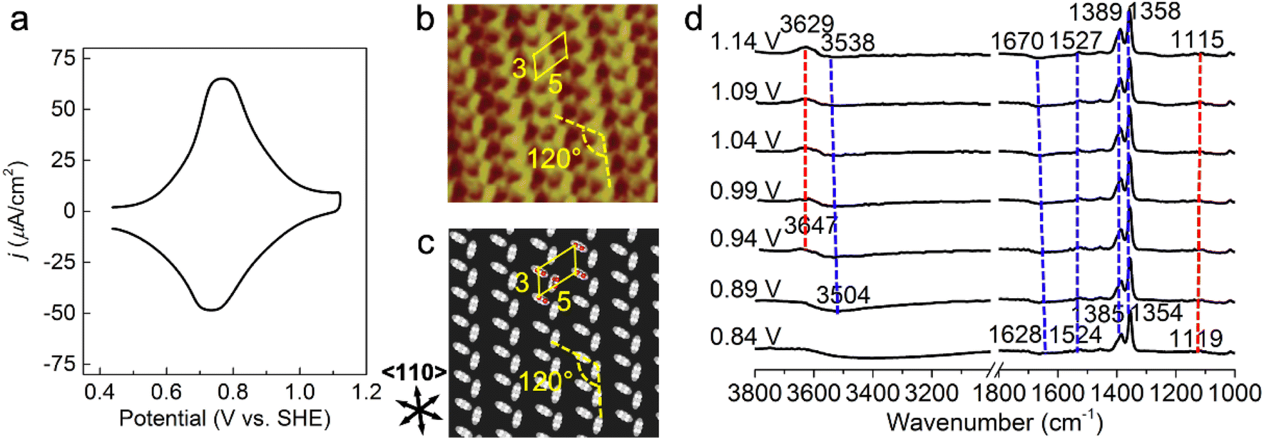 | ||
| Fig. 1 Probing atomistic structures in the Au(111)/PNBA solution interface. (a) A CV curve of Au(111) in a 0.1 M HClO4 and 1 mM PNBA aqueous solution. Scan rate: 50 mV s−1. (b) The measured STM image at 0.66 V vs. SHE.17 (c) The corresponding calculated STM image of the Au(111)(3 × 5)–2PNBA− adstructure at 0.69 V. (d) Experimental EC-IR spectra measured by SEIRAS at 0.84–1.14 V vs. SHE, using the spectrum at 0.34 V as the reference to clearly characterize the entire adsorption process of PNBA− ions. In (b), repetition lengths along two 〈110〉 directions are approximately 14 Å (a axis) and 8 Å (b axis), respectively, which correspond to five and three times the lattice constant of the (1 × 1) surface, indicating a Au(111)(3 × 5) unit cell. Image (b) adapted from ref. 22 with permission, copyright (2011) American Scientific Publishers. | ||
Determining the adsorption frame of Au(111)(3 × 5)–2PNBA in the Au(111)/PNBA solution interface
The high-resolution scanning tunneling microscopy (STM) image of PNBA− adsorbed on the Au(111) surface, measured by the Wan group (Fig. 1b),22 showed that the angle between a pair of the elongated blobs was approximately 120° in a (3 × 5) unit cell. To interpret the measured STM image, we compared it with the calculated EC-STM images of three possible Au(111)(3 × 5)–2PNBA− configurations (Fig. S1†). In these Au(111)(3 × 5)–2PNBA− configurations, the PNBA− ions vertically adsorbed on top of Au atoms by O atoms of the carboxylate group; a PNBA− at the corner of the (3 × 5) unit cell was rotated by angles of θ = 0°, 60°, or 120° from the a axis; the dihedral angle was 120° between the planes of both PNBA− ions.The calculated STM pattern (Fig. 1c) of Au(111)(3 × 5)–2PNBA− (θ = 60°) (Fig. S1b†) matches perfectly the measured one. The elongated blob deriving from the cross-section of the vertically adsorbed PNBA− charge density near the Fermi level EF is 5.47 Å (approximately 5.43 Å in the measured STM pattern) away from another elongated blob in the (3 × 5) unit cell. Pairs of elongated blobs are aligned to form wheat-like stripes extending along the 〈110〉 direction of the underlying substrate. Other STM patterns (Fig. S1d and f†) from the configurations of Au(111)(3 × 5)–2PNBA− (θ = 0°) and (θ = 120°) can be excluded because of the different blob alignments along the 〈110〉 direction and longer distances between the adjacent blobs of 6.72 and 6.80 Å than the measured one of 5.43 Å. Therefore, the structure or the frame of Au(111)(3 × 5)–2PNBA discussed below refers to the configuration in which the PNBA ion or molecule at the corner is rotated by θ = 60° from the a axis.
Building possible combined configurations with the interfacial water
Limited by the adsorbed PNBA− ions, it is difficult for EC-STM to probe water molecules in the Au(111)/PNBA solution interface. On the other hand, EC-SEIRAS can sensitively probe the chemical structures of the EC interface including the interfacial water. As shown in Fig. 1d, the sharp band associated with the interfacial water at 3647 cm−1 is also observed in our measured EC-IR spectra at 0.94 V vs. SHE, which shifts to 3629 cm−1 at 1.14 V, in good agreement with that reported in the literature.16 Besides, there are two negative-going bands at approximately 3506 and 1642 cm−1, associated with the interfacial water as well.31 All three bands are sensitive to the bias potential, and their Stark tuning slopes (STSs) are large, being −104.15, 149.61, and 141.31 cm−1 V−1, respectively. Different from these bands, the absolute STSs of the bands related to adsorbed PNBA− at 1525, 1386, 1355, and 1118 cm−1 are small and approximately 13 cm−1 V−1 as shown in Table S1.†To precisely interpret the measured EC-IR spectra related to the interfacial water by the computational methods, explicit water molecules, especially the first-nearest water layer (1st WL), should be introduced into the Au(111)(3 × 5)–2PNBA frame. We started from four possible combined Au(111)(3 × 5)–2PNBA configurations with the 1st WL as shown in Fig. 2, based on the following considerations: (i) as the average density of liquid water32 is around 1.00 g mL−1 under ambient conditions, the 1st WL (3 Å thickness) should contain nine water molecules in the frame of Au(111)(3 × 5)–2PNBA. (ii) Based on the experiments of surface probe microscopies,33–36 the hydrogen-bonding network of interfacial water should consist of five- or six-membered rings. (iii) The difference of the chemical environment induced by the water molecules self-assembling and water bonded with adsorbed PNBA− ions assembling as multi-membered rings should be taken into account. Additionally, the combined configuration of the adsorbed PNBA molecules is also included in Fig. 2 to systematically consider the possible adsorbates in the Au(111)/PNBA solution interface.
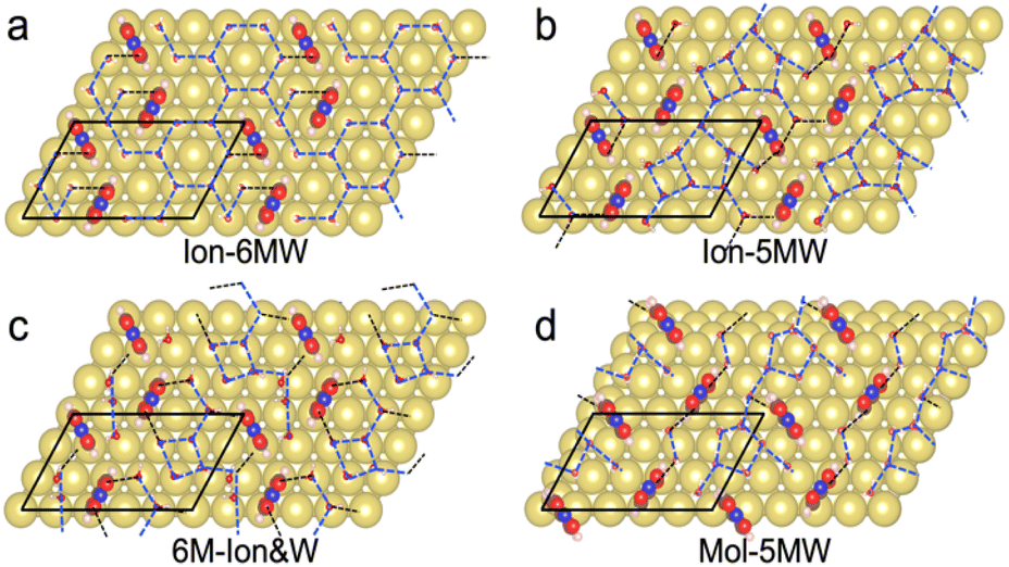 | ||
| Fig. 2 Au(111)(3 × 5)–2PNBA combined with four proposed 1st WL configurations: (a) water molecules self-assemble as hydrogen-bonding chains of six-membered rings and partly hydrogen-bond with the adsorbed PNBA− ions, denoted as Ion-6MW; (b) water molecules self-assemble as hydrogen-bonding chains of five-membered rings and partly hydrogen-bond with the adsorbed PNBA− ions, denoted as Ion-5MW; (c) water molecules and the adsorbed PNBA− ions assemble together as hydrogen-bonding flakes of six-membered rings, denoted as 6M-Ion&W; (d) water molecules self-assemble as hydrogen-bonding chains of five-membered rings and partly hydrogen-bond with adsorbed PNBA molecules, denoted as Mol-5MW. Gold, brown, pink, red, and blue balls denote Au, C, H, O, and N atoms, respectively. Interfacial water molecule is simplified as a stick model. Dashed black and blue lines denote the PNBA ion(molecule)–water hydrogen bonds and water–water hydrogen bonds, respectively. | ||
The Ion-6MW configuration can be excluded first, given that it is unstable at 0.84–1.14 V vs. SHE, which transforms into the Ion-5MW configuration during the structural optimization. Other configurations, Ion-5MW, 6M-Ion&W, and Mol-5MW, are all plausible by comparing their calculated EC-STM images (Fig. S2†) with the measured result. These patterns are nearly consistent, although there is a slight brightness segregation of the elongated blobs for the Mol-5MW configuration.
Assignment of the sharp EC-IR band related to interfacial water at approximately 3647 cm−1
In order to conveniently compare and reference the calculated EC-IR spectra for the combined configurations of Au(111)(3 × 5)–2PNBA with the 1st WL, the EC-IR spectrum of the 1st WL with six-membered rings on the bare Au(111)(2√3 × 2√3) surface (i.e., the pure WL configuration in Fig. S3†) was simulated first at 0.34 V, and is shown in Fig. 3a (the gray dashed curve). The calculated broad OH stretching band of the pure WL configuration at 3200–3800 cm−1 can be resolved into two distinct components: a higher wave number (∼3600 cm−1, the red flake in Fig. 3a) component is associated with non-hydrogen-bonded (NHB) water OH moieties (νNHB(OH) in Fig. S4a†), while the main component is associated with water molecules hydrogen-bonded with themselves (νW⋯W(OH) in Fig. S4b†). The latter contribution for the broad OH stretching band is far more significant than the former one.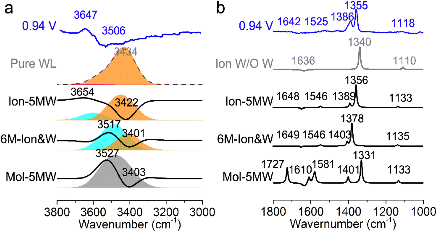 | ||
| Fig. 3 Calculated EC-IR spectra for the combined configurations of Au(111)(3 × 5)–2PNBA with the 1st WL at 0.94 V vs. SHE (a) from 3000 to 3800 cm−1; and (b) from 1000 to 1800 cm−1. The calculated EC-IR spectra have been referenced by the EC-IR spectrum of the pure WL configuration at 0.34 V. Blue curves in (a) and (b) denote the measured EC-IR spectra at 0.94 V. Red, orange, cyan, and gray flakes in (a) denote the contribution of the OH stretching mode ν(OH) of non-hydrogen-bonded water OH moieties, water molecules hydrogen-bonded with themselves, water hydrogen-bonded to the PNBA− ions, and the hybridization of the above three types of vibrations, respectively. | ||
By comparing the calculated EC-IR spectrum of the Ion-5MW configuration with the measured one at 0.94 V (Fig. 3a and S5†), it is found that the calculated band at 3654 cm−1 agrees well with the measured sharp band at 3647 cm−1, which is assigned to the OH stretching mode of water hydrogen-bonded to the adsorbed PNBA− ion (νPNBA−⋯W(OH) in Fig. S6a†). Moreover, we can exclude the other hypothetic structures that the sharp IR band is associated with the in-plane confined water layer induced by ordered adsorption of PNBA− or the non-hydrogen-bonded water OH moieties. In contrast to the former hypothesis, the vibrational frequency of the νW⋯W(OH) mode of Ion-5MW (Fig. S6b†) is found to be located at 3449 cm−1, which is close to the corresponding vibrational frequency of the pure WL 3434 cm−1, and is not evidently shifted to a higher wavenumber by the in-plane confinement. As opposed to the latter one, the vibrational frequency of the νNHB(OH) mode of Ion-5MW is shifted to a higher wavenumber around 3743 cm−1 and its spectral intensity is almost two orders of magnitude lower than those of the band counterparts of νPNBA−⋯W(OH) and νW⋯W(OH). Additionally, the measured negative-going bands related to the interfacial water at 3506 and 1642 cm−1 are found to be derived from the contributions of the νW⋯W(OH) mode and the bending mode for water hydrogen-bonded with themselves (i.e., δW⋯W(W) in Fig. S6c†), respectively.
To further verify the assignment of the sharp IR band, we calculated the EC-IR spectra for the adsorption configurations with the first- and second-nearest water layers (1st + 2nd WL). By comparing the EC-IR spectra for the configurations of the 1st WL and 1st + 2nd WL (Fig. S8a and b†) with six-membered rings in Fig. S9,† the main contribution of the spectral intensity derives from the 1st WL, whereas the 2nd WL contribution is almost one order of magnitude smaller, since the dipole responses of vibrational modes are enhanced specifically near the surface. For the configuration of Ion-5MW with the 1st + 2nd WL (Fig. S8c and d†), its EC-IR spectrum approximates to the combined configuration with the 1st WL and is slightly closer to the measured spectrum in Fig. S10.† Therefore, accurate description of the 1st WL structure is the key to realizing a quantitative spectral prediction of the adsorption system with the interfacial water. We would also like to point out that our current computational method for predicting the EC-IR spectra using a hybrid explicit/implicit solvation model has not yet been able to accurately simulate and analyse the measured asymmetric bands caused by the dynamic effect from the interfacial water layer. This problem might be solved by considering the molecular dynamics with efficient computational analysis.37–39
Determining the interfacial water structure in the Au(111)(3 × 5)–2PNBA frame
The EC-IR bands related to the interfacial water are structural-sensitive to the hydrogen-bonding network of the adlayer. With respect to the calculated spectrum of the Ion-5MW configuration in Fig. 3a, a large interval of 232 cm−1 between the bands of νW⋯W(OH) and νPNBA−⋯W(OH) is associated with the clear difference between the hydrogen-bonding interactions of W⋯W in the 5MW chains and those of PNBA−⋯W. When the adlayer forms 6M PNBA−⋯W flakes in the 6M-Ion&W configuration, the difference between the hydrogen bonds in W⋯W and PNBA−⋯W is reduced, which results in the νPNBA−⋯W(OH) band shifted from 3654 to 3517 cm−1. Besides changing the components of multi-membered hydrogen-bonding rings, the carboxyl group of the adsorbed PNBA molecules in Mol-5MW strengthens the PNBA⋯W hydrogen-bond such that the contributions from the modes of νPNBA⋯W(OH) and νW⋯W(OH) cannot be resolved clearly, while the whole EC-IR band is slightly shifted to a higher wavenumber. By comparing all the calculated EC-IR spectra of the combined configurations with the measured one in Fig. 3a and b, the bands of νPNBA−⋯W(OH), νW⋯W(OH), and δW⋯W(W) for the Ion-5MW configuration are the most consistent with the corresponding measured bands of 3647, 3506, and 1642 cm−1. As a result, the structure of the interfacial water in the frame of Au(111)(3 × 5)–2PNBA− should be the hydrogen-bonding chains of 5MW.The EC-IR bands related to the adsorbed PNBA ions or molecules are also influenced by the interfacial water due to hydrogen-bonding interactions. Different from the degenerate 1340 cm−1 band of the Au(111)(3 × 5)–2PNBA− configuration without water molecules being involved (Ion W/O W in Fig. 3b), the corresponding IR band of the Ion-5MW configuration splits into bands of 1546, 1389, and 1356 cm−1, which are assigned to the anti-symmetric and the symmetric carboxylate stretching modes of  and
and  , and the symmetric nitro group stretching mode of
  , for the adsorbed PNBA− ions in Fig. S6d–f,† respectively, while the 1110 cm−1 band is assigned to the CN stretching mode of νPNBA−(CN) in Fig. S6g.† These calculated EC-IR bands agree well with the corresponding measured bands of 1525, 1386, 1355, and 1118 cm−1. Similar to the bands related to the interfacial water, the bands of
  and
and  for the 6M-Ion&W configuration are slightly shifted to a higher wavenumber as the PNBA−⋯W hydrogen-bond strengthens. Meanwhile, the Mol-5MW configuration can be excluded, because the pair of asymmetric νPNBAasym(CO2) bands at 1610 and 1581 cm−1 for the adsorbed PNBA molecules (Fig. S7†) caused by the decrease of the molecular symmetry match poorly the single band at 1525 cm−1 in the measured EC-IR spectrum.
EC-STS, a commonly used quantity for the identification of the potential-dependent electroadsorption, is used to further confirm the structure of the water layer in the Au(111)/PNBA solution interface. Different from the small STSs of the EC-IR bands related to the adsorbed PNBA− shown in Table S1,† all absolute STSs for the measured bands related to the interfacial water, i.e.,  , σW⋯Wν(OH), and σW⋯Wδ(W), exceed 100 cm−1 V−1 at 0.84–1.14 V vs. SHE. The calculated STSs for the relative ratios of
  and
and  for the Ion-5MW configuration are 1.40 and 1.35 (Table 1), respectively, which are in good agreement with the corresponding measured values of 1.44 and 1.36, confirming Ion-5MW as the suitable candidate structure for the observed interfacial water. In this regard, the 6M-Ion&W configuration is disproved, since the relative ratios for the calculated STSs of
 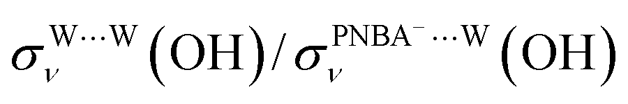 and
and 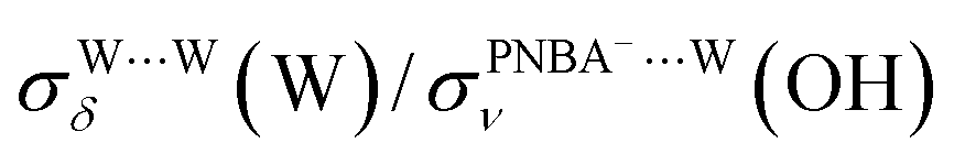 are 1.93 and 1.89, respectively, which are too large as compared to the measured ones.
| Modes | ν PNBA−⋯W(OH) | ν W⋯W(OH) | δ W⋯W(W) |
|---|---|---|---|
| a Detailed vibrational modes of νPNBA−⋯W(OH), νW⋯W(OH), and δW⋯W(W) are listed in Fig. S6. | |||
| Expt. | −104.15 | 149.61 | 141.31 |
| Ion-5MW | −80.99 | 113.25 | 109.72 |
| 6M-Ion&W | −56.60 | 109.33 | 107.24 |
| Mol-5MW | — | 59.78 | — |
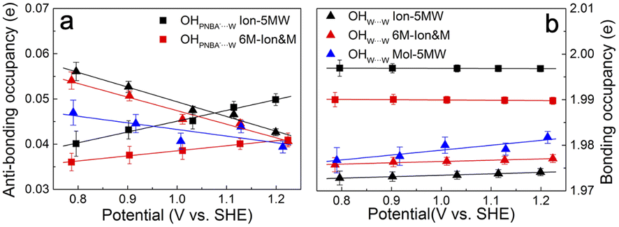
It is interesting to note from Table 1 that the STSs for the νW⋯W(OH) and the δW⋯W(W) bands are positive (149.61 and 141.31 cm−1 V−1, respectively), while the counterpart of the νPNBA−⋯W(OH) band is negative (−104.15 cm−1 V−1), indicating that the OHW⋯W bond strengthens and the OHPNBA−⋯W bond weakens as the potential increases. To understand the molecular mechanism behind this trend, natural bond orbital (NBO) analyses in the periodic implementation were carried out to quantitatively relate the chemical-bonding response to the applied potential.40 As can be seen in Fig. 4a and b, the NBO occupancies of the OHW⋯W anti-bonding orbitals decrease as the potential shifts positively, which induces the strengthening of the OHW⋯W bonds. In contrast, increasing the occupancies of the OHPNBA−⋯W anti-bonding orbitals results in the weakening of the OHPNBA−⋯W bonds. In addition, the variations in the NBO occupancies of the OH anti-bonding orbitals are more sensitive to the applied potential (Fig. 4b), since the projected electronic density of state (pDOS) of OH anti-bonding orbitals is close to the Fermi level of the specifically adsorbed PNBA− Au(111) surface (Fig. S11†). Therefore, the STSs of the bands related to the interfacial water are determined mainly by the occupancies of the OH anti-bonding orbitals of the water molecules.
 | ||
| Fig. 4 Potential-dependent NBO occupancies of the OH (a) anti-bonding and (b) bonding orbitals for the combined configurations of Au(111)(3 × 5)–2PNBA with the 1st WL. The OH orbital occupancies of water molecules hydrogen-bonded with themselves and with PNBA− ions are indicated by solid triangle and square points, respectively. Error bars represent the standard deviations for all corresponding calculated data, and points are the average values. | ||
Reaction free energy diagram and structural stability of combined configurations with the interfacial water
The potential-dependent reaction free energies ΔGre were calculated to further determine the adstructure in the Au(111)/PNBA solution interface in the potential range of 0.84–1.14 V vs. SHE. As depicted in Fig. 5a, owing to more electrostatic potential energy at the potentials, the Au(111) surface prefers the adsorption of the PNBA− ions over the PNBA molecules and hydronium ions do not appear in the structural optimization of the Mol-5MW configuration. Meanwhile, the Ion-5MW configuration is still more stable than the 6M-Ion&W configuration, as the difference of hydrogen-bonding energies between both adlayers is above 0.22 eV per unit cell. To understand the mechanism of structural stabilization for different interfacial water layers, we further calculated the potential-dependent energies of hydrogen bonds in W⋯W and PNBA−⋯W for the combined configurations. Fig. 5b shows that the most hydrogen-bonding energy is from the W⋯W hydrogen bond, which can effectively stabilize the Ion-5MW configuration. Furthermore, the hydrogen-bonding energies in PNBA−⋯W are still less than those in W⋯W for the specific configuration. The difference between hydrogen bonds in W⋯W and PNBA−⋯W for the Ion-5MW configuration is more than the counterpart for the 6M-Ion&W configuration, which agrees well with the observation of the calculated EC-IR spectra in Fig. 3a. Finally, by shifting potential positively, the hydrogen-bonding energies in W⋯W and PNBA−⋯W can be effectively tuned to reduce their difference. And the hydrogen-bonding energies in W⋯W for the combined configurations decrease, while the hydrogen-bonding energies in PNBA−⋯W increase.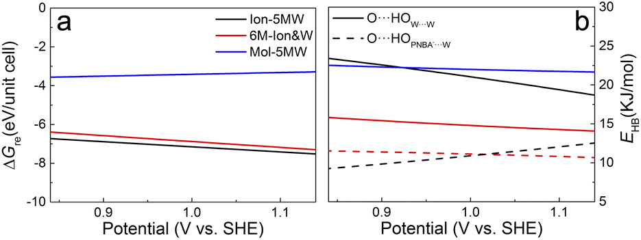 | ||
| Fig. 5 (a) and (b) Potential-dependent reaction free energies and hydrogen-bonding energies of the combined configurations of Au(111)(3 × 5)–2PNBA with the 1st WL from 0.84 to 1.14 V vs. SHE. Solid and dashed parabolas in (b) denote the hydrogen-bonding energies in the 1st WL and between the water molecule and the adsorbed PNBA, respectively. The blue solid parabola in (b) is the regression curve for both hydrogen-bonding energies of the Mol-5MW configuration with a standard deviation of 0.02 KJ mol−1. | ||
To verify the contribution from hydrogen-bonding energy for the formation of the Ion-5MW configuration and to further consider the contribution from the coverage of specifically adsorbed species, the calculations of reaction free energies of combined configurations with the 1st WL were extended to different adsorbates: pyridine (Py), benzenesulfonate (the BS− ion) and different adsorption frames: Au(111)(3 × 5)–PNBA− and Au(111)(3 × 5)–BS− in Fig. S12.† For the selected adsorbates PNBA−, Py, and BS−, the energies of the single Ion⋯W hydrogen bond are 15.32, 21.45, and 28.94 kJ mol−1, respectively. For the adsorption frames of Au(111)(3 × 5)–2PNBA− and Au(111)(3 × 5)–PNBA−, –BS−, the coverages of adsorbates decrease from 0.13 to 0.07. As the Ion⋯W hydrogen-bonding energy increases in Fig. S13,† the interfacial water layer prefers to transform the structure from Ion-5MW to the 6M-Ion&W configuration, which is consistent with the analyses from the combined configurations of Au(111)(3 × 5)–2PNBA−. Moreover, the interfacial water molecules with the decrease of the coverage of adsorbates prefer to form the Ion-6MW configuration under a low Ion⋯W hydrogen-bonding energy. Therefore, in addition to the hydrogen-bonding energy, the coverage of specifically adsorbed species also makes an important contribution to stabilizing the Ion-5MW configuration in the Au(111)(3 × 5) unit cell.
Conclusions
By comparing the calculated vibrational frequencies and STSs of the computational EC-IR spectra with those of the experimental EC-IR spectra, we conclude that the adstructure at 0.84–1.14 V vs. SHE is the interfacial water layer of the 5MW chains partially hydrogen-bonded with the Au(111)(3 × 5)–2PNBA− frame. The hydrogen-bonding interactions and the coverage of adsorbed PNBA− ions in the Au(111)(3 × 5) unit cell determine the interfacial water structure. The discovery of this interfacial water structure is made possible due to the enhancement of the dipole response for the vibrational modes near the surface, and the highly structural-sensitive νPNBA−⋯W(OH) stretching band at 3647 cm−1.By considering the hybrid explicit/implicit solvation model with a suitable structure of the first-nearest water layer, our computational method of the EC vibrational spectra can be applied not only to high coverage adsorption systems, but also to lower coverage and more general adsorption systems including interfacial water molecules. The method can be improved further by combining with the new development of the DFT method,41–43ab initio molecular dynamics and other efficient computational methods for the EC vibrational spectra to precisely consider the dynamic effect caused by the interfacial water layer.37–39 It is anticipated that the applications of more advanced spectroelectrochemical techniques, such as tip-enhanced Raman spectroscopy and nanoscale IR spectroscopy with ultrahigh spatial resolution, will provide multi-view evidence for the interfacial water structures under specific adsorption and deepen our understanding on the inner Helmholtz plane.
Computational section
The metal surfaces were modelled as p(3 × 5) and p(2√3 × 2√3) Au(111) slabs with a lattice constant of 4.21 Å and a thickness of 7 layers in a periodic box of 79.45 Å (the middle three layers were frozen in the bulk position). The Au(111)(2√3 × 2√3) slab was used in the pure interfacial water system, and the Au(111)(3 × 5) slab was used in specific adsorption systems for PNBA− and BS− ions, PNBA and Py molecules. In the adsorption systems, the adsorbates were symmetrically coordinated with each side of the metal slab. The first-principles computations were performed using the Vienna ab initio simulation package (VASP) with projector augmented wave (PAW) pseudopotentials.44,45 The exchange-correlation energies were calculated using the alternative revision of the Perdew–Burke–Ernzerhof (RPBE) functional with the generalized gradient approximation (GGA).46,47 The dispersion correction was applied in all calculations with the Becke–Johnson damping D3 method of Grimme, which was found to provide a more accurate and reliable description for various properties of water.48 We considered a 550 eV plane-wave energy cut-off and sampled the surface Brillouin zone only with the Γ point. The self-consistent field procedure was repeated until reaching a precision of 1 × 10⁻⁹ eV in the total energy. All geometries were optimized to reach residual forces on all atoms lower than 0.01 eV Å−1. The calculated STM images were constructed on the basis of Tersoff–Hamann theory with a bias voltage of −0.09 V and were visualized using the p4vasp program.49To simulate the EC-IR spectra, VASPsol implementation was employed to mimic the surface solvation effect.50 The relative permittivity εre and ionic strength I were set to 78 and 0.1 M (corresponding to a Debye screening length λ of 9.5 Å), respectively. The surface tension was set to zero (no cavitation energy). The finite difference method was employed to simulate the IR spectra. The differential step size of Cartesian coordinates Δx was set to 0.01 Å. The detailed computational method of EC-IR spectra was summarized in ref. 27 and 51. Other computational details are provided in the ESI.† The calculated potential of zero charge (PZC) of the pure WL configuration is 0.51 V vs. SHE, which is close to the measured PZC, 0.56 V.52
Experimental section
We employed a Kretschmann ATR configuration to do the in situ EC-SEIRAS experiment.8,26 Infrared radiation from a Nicolet 8700 spectrometer was shaded from the prism side at an incident angle of 60° and the totally reflected radiation was detected with a liquid-nitrogen cooled MCT detector. Spectra were acquired sequentially under potential step conditions. The spectral resolution used was 8 cm−1. All experimental EC-IR spectra were shown in absorbance units defined as −log(I/Iref), where I and Iref represent the intensities of the IR radiation at the sample and reference potential (0.34 V vs. SHE). A three-electrode spectroelectrochemical cell was employed for the EC-SEIRAS experiment. A gold wire was used as a counter electrode and a saturated calomel electrode (SCE) was used as a reference electrode. A chemically deposited and annealed Si prism/Au film electrode (20 nm thick) was used as the working electrode.53 All potentials in this work, unless otherwise specified, were quoted against the SHE, for comparison with data from first-principles calculations. The p-nitrobenzoic acid electro-adsorption experiment was performed in a 0.1 M HClO4 and 1 mM p-nitrobenzoic acid aqueous solution. Other experimental details are provided in the ESI.†Data availability
The ESI† contains the computational details, calculation of the reaction free energies and hydrogen-bonding energies of the combined configurations with interfacial water, experimental details, calculated STM patterns of possible adsorption configurations, vibrational modes of possible adsorption configurations, calculated EC-IR spectra of adsorption configurations with the 1st + 2nd WL, calculated Stark tuning slopes of vibrational bands related to adsorbed PNBA−, and literature references.Author contributions
Conceptualization of study: Y. F., S. D., X. X., and Z. Q. T.; methodology: Y. F., R. H., and H. Q.; formal analysis: Y. F. and R. H.; investigations: R. H., J. Y. Y., and Z. Y. Z.; resources: J. Y. Y. and Z. Y. Z.; writing of the draft manuscript: Y. F., R. H., and J. Y. Y.; writing, review, and editing of manuscript: S. D., X. X., Z. Y. Z., and Z. Q. T.; supervision: S. D., X. X., and Z. Q. T.; acquisition of funding: Y. F., S. D., and X. X.Conflicts of interest
There are no conflicts to declare.Acknowledgements
The authors acknowledge financial support from the National Natural Science Foundation of China (21991130, 22233002, 22102031, and 22073017) and Innovation Program for Quantum Science and Technology (2021ZD0303305). The first-principles calculations in this work were partially performed on the TianHe-HPC of the National Supercomputer Center, Tianjin.Notes and references
- Y. H. Wang, S. S. Zheng, W. M. Yang, R. Y. Zhou, Q. F. He, P. Radjenovic, J. C. Dong, S. N. Li, J. X. Zheng, Z. L. Yang, G. Attard, F. Pan, Z. Q. Tian and J. F. Li, Nature, 2021, 600, 81–85 CrossRef CAS PubMed.
- Z. W. Seh, J. Kibsgaard, C. F. Dickens, I. Chorkendorff, J. K. Nørskov and T. F. Jaramillo, Science, 2017, 355, eaad4998 CrossRef PubMed.
- I. Ledezma-Yanez, W. D. Z. Wallace, P. Sebastián-Pascual, V. Climent, J. M. Feliu and M. T. M. Koper, Nat. Energy, 2017, 2, 17031–17037 CrossRef CAS.
- H. S. Casalongue, S. Kaya, V. Viswanathan, D. J. Miller, D. Friebel, H. A. Hansen, J. K. Nørskov, A. Nilsson and H. Ogasawara, Nat. Commun., 2013, 4, 2817–2822 CrossRef.
- Z. K. Goldsmith, M. F. Calegari Andrade and A. Selloni, Chem. Sci., 2021, 12, 5865–5873 RSC.
- J. Guo, X. Z. Meng, J. Chen, J. B. Peng, J. M. Sheng, X. Z. Li, L. M. Xu, J. R. Shi, E. G. Wang and Y. Jiang, Nat. Mater., 2014, 13, 184–189 CrossRef CAS PubMed.
- S. Mubeen, J. Lee, N. Singh, S. Kramer, G. D. Stucky and M. Moskovits, Nat. Nanotechnol., 2013, 8, 247–251 CrossRef CAS PubMed.
- H. Neff, P. Lange, D. K. Roe and J. K. Sass, J. Electroanal. Chem., 1983, 150, 513–519 CrossRef CAS.
- S. G. Sun, J. Clavilier and A. Bewick, J. Electroanal. Chem., 1988, 240, 147–159 CrossRef CAS.
- D. L. Jeanmaire and R. P. Van Duyne, J. Electroanal. Chem., 1977, 84, 1–20 CrossRef CAS.
- J. F. Li, Y. F. Huang, Y. Ding, Z. L. Yang, S. B. Li, X. S. Zhou, F. R. Fan, W. Zhang, Z. Y. Zhou, D. Y. Wu, B. Ren, Z. L. Wang and Z. Q. Tian, Nature, 2010, 464, 392–395 CrossRef CAS PubMed.
- C. Y. Li, J. B. Le, Y. H. Wang, S. Chen, Z. L. Yang, J. F. Li, J. Cheng and Z. Q. Tian, Nat. Mater., 2019, 18, 697–701 CrossRef CAS PubMed.
- S. Zhu, X. Qin, Y. Yao and M. Shao, J. Am. Chem. Soc., 2020, 142, 8748–8754 CrossRef PubMed.
- A. J. Lucio and S. K. Shaw, J. Phys. Chem. C, 2015, 119, 12523–12530 CrossRef CAS.
- A. Goyal, G. Marcandalli, V. A. Mints and M. T. M. Koper, J. Am. Chem. Soc., 2020, 142, 4154–4161 CrossRef CAS PubMed.
- H. Noda, L. J. Wan and M. Osawa, Phys. Chem. Chem. Phys., 2001, 3, 3336–3342 RSC.
- K. Hyun, S. Kang, J. Kim and Y. Kwon, ACS Appl. Mater. Interfaces, 2020, 12, 23635–23643 CrossRef CAS PubMed.
- M. Kaur Aulakh, R. Sharma, B. Pal and R. Prakash, Sol. Energy, 2020, 196, 427–436 CrossRef CAS.
- T. Zhu, J. Su, J. Alvarez, G. Lefèvre, F. Labat, I. Ciofini and T. Pauporté, Adv. Funct. Mater., 2019, 29, 1903981 CrossRef.
- X. Y. Xiao and S. G. Sun, Electrochim. Acta, 2000, 45, 2897–2902 CrossRef CAS.
- X. K. Xue, J. Y. Wang, Q. X. Li, Y. G. Yan, J. H. Liu and W. B. Cai, Anal. Chem., 2008, 80, 166–171 CrossRef CAS PubMed.
- L. Yang, T. Chen, D. Wang and L. J. Wan, J. Nanosci. Nanotechnol., 2011, 11, 4800–4805 CrossRef CAS PubMed.
- J. M. Delgado, R. Blanco, J. M. Orts, J. M. Pérez and A. Rodes, J. Phys. Chem. C, 2008, 113, 989–1000 CrossRef.
- A. P. Sandoval, J. M. Orts, A. Rodes and J. M. Feliu, J. Phys. Chem. C, 2011, 115, 16439–16450 CrossRef CAS.
- B. Han, Z. Li and T. Wandlowski, Anal. Bioanal. Chem., 2007, 388, 121–129 CrossRef CAS PubMed.
- P. Lange, V. Glaw, H. Neff, E. Piltz and J. K. Sass, Vacuum, 1983, 33, 763–766 CrossRef CAS.
- Y. Fang, J. C. Dong, S. Y. Ding, J. Cheng, J. M. Feliu, J. F. Li and Z. Q. Tian, Chem. Sci., 2020, 11, 1425–1430 RSC.
- Y. Fang, S. Y. Ding, M. Zhang, S. N. Steinmann, R. Hu, B. W. Mao, J. M. Feliu and Z. Q. Tian, J. Am. Chem. Soc., 2020, 142, 9439–9446 CrossRef CAS PubMed.
- J. B. Le, Q. Y. Fan, J. Q. Li and J. Cheng, Sci. Adv., 2020, 6, eabb1219 CrossRef CAS PubMed.
- P. Li, J. Huang, Y. Hu and S. Chen, J. Phys. Chem. C, 2021, 125, 3972–3979 CrossRef CAS.
- K. I. Ataka, T. Yotsuyanagi and M. Osawa, J. Phys. Chem., 1996, 100, 10664–10672 CrossRef CAS.
- G. S. Kell, J. Chem. Phys., 1975, 62, 3496–3503 CrossRef CAS.
- Y. G. Kim, S. L. Yau and K. Itaya, J. Am. Chem. Soc., 1996, 118, 393–400 CrossRef CAS.
- H. Ogasawara, B. Brena, D. Nordlund, M. Nyberg, A. Pelmenschikov, L. G. Pettersson and A. Nilsson, Phys. Rev. Lett., 2002, 89, 276102–276105 CrossRef CAS PubMed.
- J. Carrasco, A. Michaelides, M. Forster, S. Haq, R. Raval and A. Hodgson, Nat. Mater., 2009, 8, 427–431 CrossRef CAS PubMed.
- C. Zhang, T. Liu, D. Y. Cao and J. Guo, Sci. Sin.: Chim., 2022, 52, 940–946 Search PubMed.
- A. Yamakata, E. Soeta, T. Ishiyama, M. Osawa and A. Morita, J. Am. Chem. Soc., 2013, 135, 15033–15039 CrossRef CAS PubMed.
- T. Joutsuka and A. Morita, J. Chem. Theory Comput., 2016, 12, 5026–5036 CrossRef CAS PubMed.
- T. Hirano, N. Yazawa, L. Wang and A. Morita, J. Chem. Phys., 2022, 157, 124105 CrossRef CAS PubMed.
- B. D. Dunnington and J. R. Schmidt, J. Chem. Theory Comput., 2012, 8, 1902–1911 CrossRef CAS PubMed.
- Y. Wang, Y. Li, J. Chen, I. Y. Zhang and X. Xu, JACS Au, 2021, 1, 543–549 CrossRef CAS PubMed.
- Z. Liu, Z. Chen and X. Xu, CCS Chem., 2021, 3, 904–915 CrossRef CAS.
- Y. Gu, Z. Zhu and X. Xu, J. Chem. Theory Comput., 2021, 17, 4860–4871 CrossRef CAS PubMed.
- G. Kresse and J. Furthmuller, Phys. Rev. B, 1996, 54, 11169–11186 CrossRef CAS PubMed.
- G. Kresse and D. Joubert, Phys. Rev. B, 1999, 59, 1758–1775 CrossRef CAS.
- J. P. Perdew, K. Burke and Y. Wang, Phys. Rev. B, 1996, 54, 16533–16539 CrossRef CAS PubMed.
- B. Hammer, L. B. Hansen and J. K. Nørskov, Phys. Rev. B, 1999, 59, 7413–7421 CrossRef.
- S. Grimme, S. Ehrlich and L. Goerigk, J. Comput. Chem., 2011, 32, 1456–1465 CrossRef CAS PubMed.
- J. Tersoff and D. R. Hamann, Phys. Rev. B, 1985, 31, 805–813 CrossRef CAS PubMed.
- K. Mathew, V. S. C. Kolluru, S. Mula, S. N. Steinmann and R. G. Hennig, J. Chem. Phys., 2019, 151, 234101–234108 CrossRef PubMed.
- Y. Fang, R. Hu, S. Y. Ding and Z. Q. Tian, J. Electroanal. Chem., 2021, 896, 115337–115343 CrossRef CAS.
- J. D. Goodpaster, A. T. Bell and M. Head-Gordon, J. Phys. Chem. Lett., 2016, 7, 1471–1477 CrossRef CAS PubMed.
- H. Miyake, S. Ye and M. Osawa, Electrochem. Commun., 2002, 4, 973–977 CrossRef CAS.
Footnote |
| † Electronic supplementary information (ESI) available. See DOI: https://doi.org/10.1039/d3sc00473b |
| This journal is © The Royal Society of Chemistry 2023 |