
 Open Access Article
 This Open Access Article is licensed under a Creative Commons Attribution-Non Commercial 3.0 Unported Licence
Atomic structural changes in the formation of transition metal tungstates: the role of polyoxometalate structures in material crystallization†
Susanne Linn
Skjærvø
,
Andy S.
Anker
 ,
Magnus C.
Wied
,
Emil T. S.
Kjær
,
Mikkel
Juelsholt
,
Troels Lindahl
Christiansen
and
Kirsten M.
Ø. Jensen
*
,
Magnus C.
Wied
,
Emil T. S.
Kjær
,
Mikkel
Juelsholt
,
Troels Lindahl
Christiansen
and
Kirsten M.
Ø. Jensen
*
Department of Chemistry and Nano-Science Center, University of Copenhagen, 2100 Copenhagen Ø, Denmark. E-mail: kirsten@chem.ku.dk
First published on 6th April 2023
Abstract
Material nucleation processes are poorly understood; nevertheless, an atomistic understanding of material formation would aid in the design of material synthesis methods. Here, we apply in situ X-ray total scattering experiments with pair distribution function (PDF) analysis to study the hydrothermal synthesis of wolframite-type MWO4 (M![[thin space (1/6-em)]](https://www.rsc.org/images/entities/char_2009.gif) :Mn, Fe, Co, Ni). The data obtained allow the mapping of the material formation pathway in detail. We first show that upon mixing of the aqueous precursors, a crystalline precursor containing [W8O27]6- clusters forms for the MnWO4 synthesis, while amorphous pastes form for the FeWO4, CoWO4 and NiWO4 syntheses. The structure of the amorphous precursors was studied in detail with PDF analysis. Using database structure mining and an automated modelling strategy by applying machine learning, we show that the amorphous precursor structure can be described through polyoxometalate chemistry. A skewed sandwich cluster containing Keggin fragments describes the PDF of the precursor structure well, and the analysis shows that the precursor for FeWO4 is more ordered than that of CoWO4 and NiWO4. Upon heating, the crystalline MnWO4 precursor quickly converts directly to crystalline MnWO4, while the amorphous precursors transform into a disordered intermediate phase before the crystalline tungstates appear. Our data show that the more disordered the precursor is, the longer the reaction time required to form crystalline products, and disorder in the precursor phase appears to be a barrier for crystallization. More generally, we see that polyoxometalate chemistry is useful when describing the initial wet-chemical formation of mixed metal oxides.
:Mn, Fe, Co, Ni). The data obtained allow the mapping of the material formation pathway in detail. We first show that upon mixing of the aqueous precursors, a crystalline precursor containing [W8O27]6- clusters forms for the MnWO4 synthesis, while amorphous pastes form for the FeWO4, CoWO4 and NiWO4 syntheses. The structure of the amorphous precursors was studied in detail with PDF analysis. Using database structure mining and an automated modelling strategy by applying machine learning, we show that the amorphous precursor structure can be described through polyoxometalate chemistry. A skewed sandwich cluster containing Keggin fragments describes the PDF of the precursor structure well, and the analysis shows that the precursor for FeWO4 is more ordered than that of CoWO4 and NiWO4. Upon heating, the crystalline MnWO4 precursor quickly converts directly to crystalline MnWO4, while the amorphous precursors transform into a disordered intermediate phase before the crystalline tungstates appear. Our data show that the more disordered the precursor is, the longer the reaction time required to form crystalline products, and disorder in the precursor phase appears to be a barrier for crystallization. More generally, we see that polyoxometalate chemistry is useful when describing the initial wet-chemical formation of mixed metal oxides.
Introduction
Formation pathways during synthesis can have a huge impact on a material's structure and properties, and yet, our knowledge regarding the mechanisms involved in material formation during wet-chemical synthesis is poor. Traditionally, nucleation has been described in terms of classical nucleation theory, which uses simple thermodynamic functions to describe the formation of the nuclei that lead to particles. Classical nuclei are considered to be hard spheres with a sharp interface between the solution and solid, with the same atomic structure and properties of the final crystalline material. This is highly approximate, and classical nucleation theory does not reflect the complex chemical reactions that take place during synthesis.1 More recently, ‘non-classical nucleation’ theories have therefore been introduced, including the existence of ‘pre-nucleation clusters’, which are considered to be assemblies of atoms existing in the early stages of the synthesis.2 These species may meet in solution and aggregate, and crystallization within the aggregate can lead to the formation of nuclei from which nanoparticles can grow.3,4 While the development of non-classical nucleation theory has widened our understanding of nucleation processes, many aspects of nucleation are still left in the dark. Specifically, we are missing atomistic structural information on the clusters and nuclei as they form and grow into particles. For example, the clusters involved in the nucleation process are generally described as amorphous assemblies of atoms, even though they are key to understanding material formation.In order to unravel the cluster chemistry at play in nucleation processes, we here investigate the nucleation of mixed metal oxides such as wolframite-type tungstates (Fig. 1a). Wolframite-type MWO4 are complex tungsten(+VI)-based oxides containing bivalent 3d-metals such as Mn, Fe, Co, Ni, Cu and Zn.5 These materials have interesting electrochemical properties, which are useful in electro- and photocatalysis,5 and changes in their catalytic behaviour have been observed as the structure goes from crystalline to amorphous.6 Hydro- and solvothermal syntheses of wolframite-type tungstates have been studied extensively in the literature,5,7–10 and usually involves simple mixing of metal cation aqueous solutions, with optional pH adjustment followed by hydro- or solvothermal treatment. The formation mechanism of MWO4 has not yet been given much attention, but recent insights on the hydrothermal formation of WO3 by Juelsholt et al.11 and ZnWO4 by Bøjesen et al.12 have shown that clusters with structures similar to those well-known from classical polyoxometalate (POM) chemistry13–19 might play an important role.12 From in situ X-ray total scattering studies, it was shown that ZnWO4 forms via a sandwich-type POM ion. This sandwich ion, with the general formula [M4(H2O)2(XW9O34)2]n− with metal M and heteroatom X as described by Limanski et al.,20 can be seen in Fig. 1b. The sandwich structure is simply described as two Keggin fragments (Fig. 1c) sandwiching a bridging layer of 3d metal atoms.21 Analogous ions have been found for samples containing M = Mn2+, Fe2+, Fe3+ or Cu2+,20,22,23 and for a mix of several different metal cations in the mineral ophirite.23
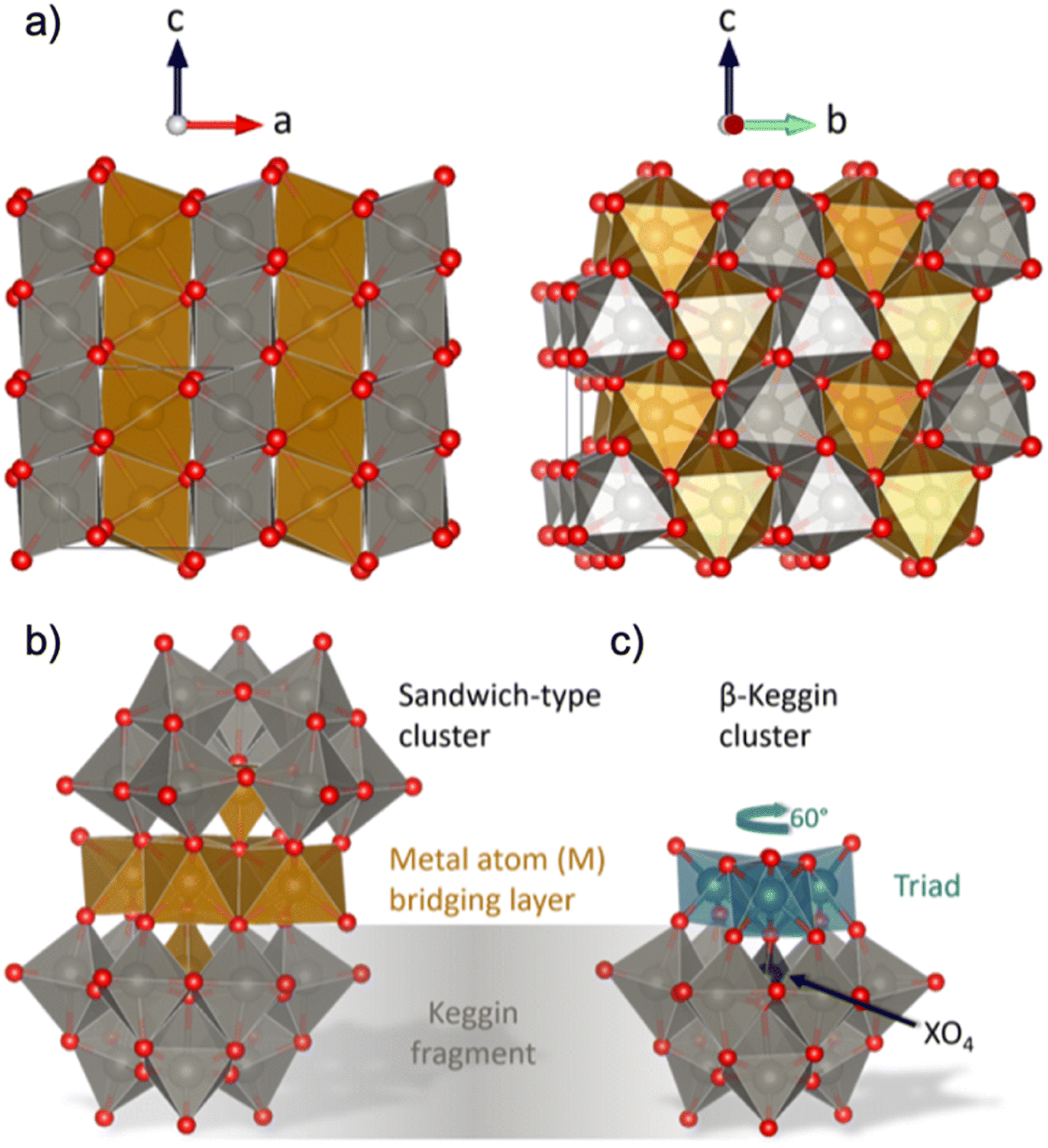 | ||
| Fig. 1 (a) Visualization of the wolframite-type MWO4 structure. The 3d-metal atoms (M) are orange, tungsten atoms are grey and oxygen atoms are red. The structure consists of chains of edge-sharing metal–oxygen octahedra, and the chains are linked with each other by corner-sharing. (b) Illustration of a sandwich-type cluster, consisting of two Keggin fragments and a 3d metal (M) bridging layer. Each Keggin fragment is missing a triad (i.e. a group of three edge-sharing [WO6]10− octahedra) which is replaced by the bridging layer, and is cradling a heteroatom (X), which in some cases is the same element as in the bridging layer. The bridging layer connects to the fragments with a rotational angle typical for (c) β-Keggins, 60° compared to the α-Keggin. Structures are drawn with VESTA.24 | ||
To shed light on the formation process of complex oxides and the role of POM clusters, we present an in situ time-resolved X-ray total scattering study of MWO4 formation for M = Mn, Fe, Co and Ni. We analyse the total scattering data through pair distribution function (PDF) analysis, which allows for extraction of structural information from all stages of the synthesis, i.e. from ions in solution, amorphous intermediates and the crystalline products.1,11,25–31 Our data show that POM-like structures play a role in crystallization in all the tungstates we have investigated, although their structure and the process differ depending on the transition metal in the structure. None of the compounds studied here were formed from the Tourné sandwich cluster previously observed during the formation of ZnWO4.12 Thus, to identify new, relevant cluster structures from PDF, we have applied a new modelling strategy involving machine learning (ML). We use our newly developed ML method, ML-MotEx,32 which allows us to extract important structural motifs through SHAP (SHapley Additive exPlanation) values.33,34 This method allowed mapping of structural changes in the entire reaction process, following how different structural motifs appear and disappear in the material as they form. We show that the formation of MnWO4 proceeds directly from a crystalline precursor structure, while that of FeWO4, CoWO4 and NiWO4 proceeds from an amorphous precursor over an intermediate. The amorphous precursor structure can be described through a skewed sandwich cluster with Keggin-like fragments, previously seen in crystalline (Ni6(H2O)9(OH)3(HSiW9O34))2(H2O)12.
The precursor clusters observed in the case of CoWO4 and NiWO4 are more disordered than that for FeWO4. This disorder appears to affect the reaction process and kinetics, as we only observe the formation of crystalline FeWO4 in the time scale of the in situ experiments, while CoWO4 and NiWO4 retain their intermediate structure. The experiments and PDF analysis thus provide an understanding of how mixed metal oxides form in solution, and the role polyoxometalates play in this regard.
Results and discussion
Overview of the phase evolution
We performed in situ X-ray total scattering with a time-resolution of 5 seconds/frame of the formation of four different tungstates, MnWO4, FeWO4, CoWO4 and NiWO4. In all cases, the synthesis was done hydrothermally. As described in detail in the Experimental Methods section, an aqueous solution of Na2WO4·2H2O was mixed with an aqueous solution of (1) MnCl2·4H2O (MnWO4 synthesis), (2) FeCl2·4H2O (FeWO4 synthesis), (3) CoCl2·6H2O (CoWO4 synthesis) and (4) NiCl2·6H2O (NiWO4 synthesis). All the mixtures became paste-like (i.e. opaque with high viscosity) immediately upon mixing, but with lower viscosity when moving right along the 4th period in the periodic table, from Mn to Ni. The pastes had different colours; beige, medium brown, bright purple and pale green for the MnWO4, FeWO4, CoWO4 and NiWO4 synthesis, respectively, as can be seen from Fig. S1 in the ESI.† The hydrothermal syntheses were performed at 160 °C and a static pressure of 100 bar.We first consider the reaction leading to FeWO4. Fig. 2a presents the time-resolved PDFs calculated from in situ total scattering data for the FeWO4 synthesis. We observe three different phases in the process: a precursor, an intermediate phase and a product. The precursor phase has only short range order, with significant PDF peaks up to r ≈ 5 Å and weak oscillations up to r ≈ 10 Å. These oscillations indicate that the precursor is amorphous and most likely does not consist of isolated clusters in solution, as also expected from the pasty appearance of the mixtures. The intensity of the strongest peaks of the precursor phase (around 3–4 Å) decreases upon heating, and the small peaks above 5 Å seem to shift slightly upon applying heat. The precursor phase remains for approx. 1 min of heating, at which point the transient intermediate phase with limited long-range order appears, persisting for ca. 10 s. The intermediate phase transforms into a final crystalline product phase. Contour plots of the data obtained for the MnWO4, CoWO4 and NiWO4 syntheses are shown in Fig. S2 in the ESI.†
 | ||
| Fig. 2 (a) Time-resolved PDFs calculated from in situ total scattering data showing the evolution from the FeWO4 precursor structure, via an intermediate phase to a product at 160 °C and 100 bar. Dashed lines have been added to highlight the region of the intermediate phase. (b) PDFs and (c) F(Q) from in situ total scattering data of intermediate and product phases present during the MWO4 (M = Mn, Fe, Co, Ni) syntheses at 160 °C and 100 bar. The grey areas highlight crucial features which are discussed in the text. | ||
Fig. 2b and c show PDFs and reduced structure functions F(Q) for all phases observed. The same data with wider r and Q ranges plotted are included in Fig. S3 in the ESI.† The MnWO4 and FeWO4 reactions produce very similar phases with the well-known tungstate structure as discussed further below. However, we do not observe crystalline product phases for the CoWO4 and NiWO4 experiments in the reaction time and under the conditions of our in situ experiment. Instead, the phases observed at the end of the experiment have a structure similar to the FeWO4 intermediate phase. The similarity between these three intermediate phases is highlighted in Fig. S4 in the ESI,† where ex situ data of this phase are also shown to confirm stability under ambient conditions. Note that the samples described in Fig. S4† are hydrothermally synthesized in a stainless-steel autoclave (described in detail in the Experimental methods section), i.e. at a temperature and pressure very different from that of the in situ study. The reaction may thus proceed differently; however, the structure of the ex situ samples and the intermediate seen in the in situ study appear similar. The literature suggests that a higher reaction temperature or subsequent annealing is needed to form crystalline product phases for the CoWO4 and NiWO4 reactions.35–38
Overview of local structural changes
In Fig. 2b, we have highlighted the range 3–4 Å of the PDFs (labelled “#1”). In this region, we find peaks originating from nearest-neighbour metal–metal polyhedra, and specifically, the two peaks at r ≈ 3.3 Å and r ≈ 3.7 Å originate from metal–metal distances between edge-sharing (ES) and corner-sharing (CS) metal–oxygen octahedra, respectively. As highlighted in Fig. 3a–d, the data show a significantly higher degree of edge-sharing in the precursor phases compared to in the crystalline product phases. To study this transition from precursor to product phases, we first analysed these two peaks with a simple, model-free approach by fitting the peaks with Gaussian functions, as described in more detail in the Experimental methods section. In Fig. 3e, we plot the calculated ratio between the intensity of the edge- and corner-sharing peaks (ES/CS) along the reaction for each synthesis. When heating starts, the ES/CS intensity ratio decreases for all the reactions after a delay. The MnWO4 reaction has the lowest ES/CS intensity ratio decrease, and the ratio stabilises at the same time as the crystalline product phase forms. The ES/CS intensity ratios for the FeWO4 and CoWO4 precursor phases are similar. After a slightly slower onset for the FeWO4 reaction compared to for the CoWO4 reaction, they have the same EC/CS intensity ratio at 1.1 min, where they form the same intermediate phase. While CoWO4 remains at this EC/CS intensity ratio, FeWO4 proceeds to form a crystalline product phase, with a slightly higher ES/CS intensity ratio compared to that of the intermediate phase. The NiWO4 reaction, which just like CoWO4 did not produce a crystalline product phase, ends up at the same ES/CS intensity ratio as the CoWO4 reaction. In conclusion, the lowest ES/CS intensity ratio throughout the reactions can be observed when transitioning through the intermediate phase, i.e. the intermediate phase has the lowest degree of edge-sharing (or highest degree of corner-sharing).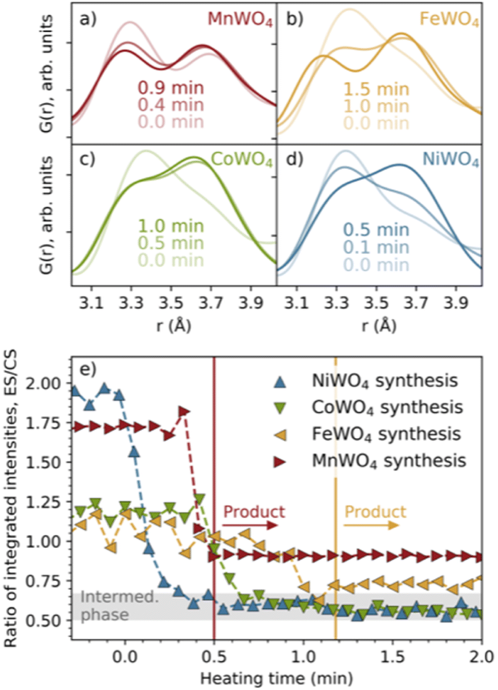 | ||
| Fig. 3 Closer view of the peaks in the PDFs indicating edge- (ca. 3.3 Å) and corner-sharing (ca. 3.6–3.7 Å) for the (a) MnWO4, (b) FeWO4, (c) CoWO4 and (d) NiWO4 syntheses. (e) The ratio between the integrated intensities of these peaks with heating time. The vertical lines show the time when the MnWO4 and FeWO4 products are formed. The grey area shows the ES/CS range where the intermediate phase is observed. | ||
The structure of the FeWO4 and MnWO4 product phases
Having established the phase evolution, we now look further to the product phases. Despite having different reaction schemes, the MnWO4 and FeWO4 syntheses both produced a similar product phase, which could be successfully fitted (Fig. 4a and b and S5†) to the wolframite-type MnWO4 and FeWO4 structures.39,40 Sequential fits of the time-resolved data were performed to follow structural changes taking place after the formation of the product phase. The scale factor, crystallite size, isotropic atomic displacement parameters (ADPs) for W and Mn/Fe, and the atomic position deviation from the centre of the W–O octahedra along the y-axis for W were refined. The results are presented in Fig. 4c and S6.† Generally, the model provides a good description of the data as seen from the Rw factor (Fig. S6†) which is below 0.2 after the formation of the (Mn/Fe)WO4 phase and disappearance of intermediate/precursor phases. The scale factors show that the onset of the formation is later for FeWO4 compared to MnWO4. While the scale factor of MnWO4 increases abruptly when transitioning directly from the crystalline precursor phase to MnWO4, the scale factor of FeWO4 increases slightly slower as the product phase grows from the intermediate phase. The crystallite size of both MnWO4 and FeWO4 continues to increase after the scale factor has reached its maximum for both reactions, indicating that the crystallites may continue to grow through Ostwald ripening as the reaction proceeds. Note that the crystallite size of especially the MnWO4 particles grows beyond what can be resolved from the rapid acquisition PDF (RA-PDF)41 measurements, and we therefore only rely on trends rather than absolute sizes. | ||
| Fig. 4 Fits to the (a) MnWO4 and (b) FeWO4 product phases, using wolframite-MWO4 structures from the ICSD (code 67906 (ref. 42) and 26843,43 respectively). Details of the fits are found in tables of Fig. S6 in the ESI.† (c) Results from reverse sequential real space Rietveld refinements of MnWO4 and FeWO4 structures to the PDFs in the range of 1.3–60 Å. Scale factor, crystallite size (cr. size) in nm and isotropic ADPs (uiso in Å2) for W and Mn/Fe are shown in addition to ΔWy, which is the atomic position deviation of W from the octahedral center (defined as 0.13), along the y-axis. The time range where the FeWO4 intermediate phase is present is highlighted with a grey colour. | ||
The isotropic ADPs of Mn/Fe and W decrease during crystallization, indicating that the structural order is increasing. This trend is more apparent for FeWO4 compared to MnWO4, which indicates that a less ordered product will initially form when it grows from a less crystalline phase, i.e. the FeWO4 intermediate in contrast to the crystalline MnWO4 precursor phase. The same conclusion can also be drawn from the deviation of the W atomic position from the octahedral center (ΔWy), where a larger deviation is seen in the refined crystal structure from the early stages of crystallization. The final deviation of the W atom from the octahedral center refines to be slightly larger for MnWO4 than for FeWO4. However, the difference observed here may be within the uncertainties of the refinements, and we cannot relate this difference to the formation mechanism.
MWO4 (M = Fe, Co, Ni) intermediate: relation to the product phase
The literature suggests that the intermediate phase appearing during the MWO4 reaction is a nanostructured or ‘amorphous’ wolframite-type MWO4,35,38,42–44i.e. having a similar structure to the product phase discussed above. When comparing their PDFs (Fig. 2b) we see a difference in the ratio of the PDF peak intensity from edge- and corner-sharing metal–oxygen octahedra, and the same two peaks separate more in the product compared to in the intermediates. Also, the PDF peak at r ≈ 4.6 Å is splitting up when transitioning from the intermediate to the product, highlighted in grey area #2. Still, the intermediate and product phase PDFs have some similarities, and so we hypothesize that the same building blocks, i.e. the local structure, might be present in the two phases. To test this hypothesis, we fitted the wolframite-type CoWO4 (ref. 45) structure to the CoWO4 intermediate phase up to just 20 Å, and the result is presented in Fig. 5. The atomic positions of Co and W are refined in the y-direction, and this refinement results in a centering of metal atoms inside the metal–oxygen octahedra, removing the splitting of the peak at 4.6 Å, highlighted in the grey area in Fig. 5. The local structure of the intermediate phase can thus be described fairly well with a disordered wolframite-type structure. | ||
| Fig. 5 Fit of the wolframite-CoWO4 structure41 to the CoWO4 intermediate phase (a) without and (b) with refined Co and W atomic positions. Scale factor unit cell parameters, isotropic ADPs, δ2 and the atomic positions of Co and W along the y-direction were refined. The refinement results are given in Table S1 in the ESI.† | ||
The fact that the local structure of the intermediate phase can be described by a disordered wolframite-type MWO4 structure leads to the assumption that the similarly positioned peaks in the F(Q) data of the intermediate and product phases could originate from the same lattice planes in the MWO4 structure. By assuming this, the significantly narrow Bragg peak seen from the intermediate phases at 2.5 Å−1 (Fig. 2 and S4†) could originate from the (002) or (021) reflections, as suggested by both He et al.35 and Wang et al.38 This points to the intermediate phase crystallites being anisotropic, with significant growth along the b- or c-direction. By connecting this observation to the low degree of edge-sharing calculated for the intermediate phase (Fig. 3) we suggest that the anisotropic growth occurs mainly in the b-direction, as this direction is where chains of equal metal type connect through corner-sharing.
Analysis of precursor structure motifs using structure mining
We now turn to analysis of the precursor structure before establishing the reaction mechanism. The PDFs from the four precursor compounds are plotted in Fig. 6. In the figure, we also compare the PDFs from the four mixed precursor pastes with those of their respective unmixed aqueous solutions (MCl2·xH2O, M = Mn, Fe, Co, Ni and Na2WO4·2H2O).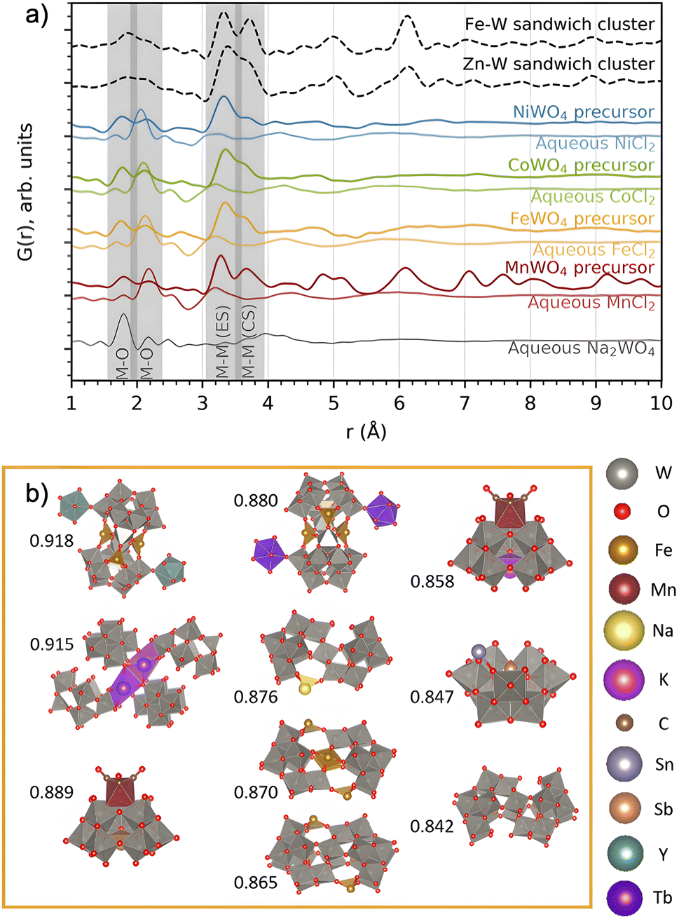 | ||
| Fig. 6 (a) PDFs of the precursors forming on mixing each of the metal chloride precursors with Na2WO4 in water, compared to that of the individual precursors in water. The PDFs of the Zn–W and Fe–W sandwich-type clusters8,20 described by Bøjesen et al.12 and Barats et al.22 are plotted for comparison. (b) The ten best suggestions for describing the FeWO4 precursor mixture, found by sifting through databases. Pearson correlation fitting was performed between calculated PDFs of all relevant clusters extracted from structures in the COD + ICSD databases and the obtained PDF in the range of 1–5 Å. Correlation coefficients are placed to the left of each structure. The structure visualizations were performed with VESTA.24 | ||
The PDFs of the precursor pastes for the FeWO4, CoWO4 and NiWO4 syntheses are almost identical. As marked in the figure, the PDFs have significant peaks at r ≈ 1.8 Å and r ≈ 2.2 Å, which are expected to arise from metal–oxygen distances in [MOx] units. Additionally, nearest-neighbour metal–metal distances between edge- and corner-sharing [MOx] octahedra are indicated by the peaks at r ≈ 3.3 Å and r ≈ 3.6 Å, as discussed above. The PDFs of the individual precursors dissolved in water show no such signs of significant edge- and corner-sharing W/M–O octahedra, showing that mixing of the aqueous precursors in water leads to the formation of new precursor phases.
The MnWO4 precursor is crystalline. The F(Q) for the MnWO4 precursor shows clear Bragg peaks and the PDF shows that the structural range goes beyond 40 Å (Fig. 2). No structure in the COD or ICSD databases satisfyingly described the entire structure, but the local range (1–8 Å) was successfully described by the structure Na4Mn[Mo8O27]·20H2O46 where Mo was replaced with W (see the fit and structure in Fig. S7†). This structure can be described as [W8O27]6−, units linked together in chains by Mn2+, Na+ and H2O. Each [W8O27]6− unit is approx. 8 Å in size, which corresponds to the successful fitting range. Therefore, it is likely that the [W8O27]6− unit is the dominating motif of the structure, and that the long-range deviation from the model arises from a different linking of these units.
The FeWO4, CoWO4 and NiWO4 precursors are all amorphous. In Fig. 6a, we compare their PDFs with calculated PDFs from known clusters, which could be expected to form the zinc tungstate sandwich cluster observed in the synthesis of ZnWO4 (ref. 12) and the equivalent iron tungstate sandwich cluster reported by Barats et al.22 (Fig. 1). When comparing these PDFs, it is clear that the structures of the FeWO4, CoWO4 and NiWO4 precursors observed in this study have a local structure similar to the sandwich clusters, however, with less order. A fit with this structure shows significant features in the difference curve, as seen in Fig. S8 in the ESI.† We therefore also wanted to investigate if other, well-known cluster structures would fit the PDF. Many relevant compounds and structures are reported in the literature and databases. All chemically relevant structures (i.e. structures containing elements present in the synthesis) were filtered out from the Crystallography Open Database (COD) and Inorganic Crystal Structure Database (ICSD). Using the CIFs obtained from this filtering, POM cluster structures were isolated, resulting in ca. 800 discrete cluster models. Their PDFs were calculated using the same Qmin, Qmax and Qdamp values as for the experimental PDF. The calculated PDFs were automatically compared to the experimental PDFs using the Pearson correlation, where the PDF range from 1–5 Å was included. This is a simple but fast way of quantifying the similarities between two curves using the Pearson coefficient.47
The ten cluster structures giving the highest Pearson correlation value for the FeWO4 precursor phases are shown in Fig. 6b. The equivalent for the CoWO4 and NiWO4 precursors are found in Fig. S9.† All the suggested structures for the FeWO4 precursor contain Keggin fragments, [W9O34].14 The CoWO4 results were almost identical to those of the FeWO4 precursor, but for the NiWO4 precursor, some of the suggested structures had more edge-sharing octahedra, for instance the heptatungstate cluster [W7O24]6−.48 While this method has allowed us to identify the main structural motifs, the clusters found from the Pearson analysis cannot give a satisfactory fit of the PDF, especially in the range above 4 Å. We therefore move on to further investigate which structural features and connection of Keggin fragments can describe the precursor PDFs.
Precursor structure analysis using ML-MotEx
It is clear from the suggested clusters presented in Fig. 6b that the (Fe/Co/Ni)WO4 precursor phases contain tungsten-based Keggin fragments. If we assume a formation mechanism involving some version of a Tourné-type sandwich cluster as seen in Fig. 1b, the most chemically relevant cluster containing such fragments is the Fe–W sandwich cluster reported by Barats et al.22 We already know that this cluster in itself cannot describe the experimental PDF, but we can investigate whether there are parts of this structure which agree with our data and from that, further analyse the precursor structure. For this purpose, we use a recently developed automated modelling method, ML-MotEx32 in which thousands of all fragments based on a starting cluster model are built and tested against an experimental PDF.29 Using these fits and an explainable ML algorithm, it is possible to obtain information on the importance of every single atom in the starting model for the fit quality. The method is described in detail by Anker et al.32 and an overview is given in the ESI.†We use ML-MotEx here for analysis of the PDFs obtained from the FeWO4 synthesis, with the Fe–W sandwich cluster23 used as the starting model. We first created a structure catalogue with 10000 structure motifs, which were all fragments built of the Fe–W sandwich cluster with a varying number of atoms. As described in detail in the ESI,† each generated fragment was fitted to each PDF obtained from the reaction, yielding a Rwp value for each fit. These fits and their corresponding Rwp values were then fed to the explainable ML algorithm, which was trained to predict the Rwp value from a structure motif. Afterwards, the importance and effect of each atom on the fits could be explained using SHapley Additive explanation (SHAP) values, as described in detail in the ESI and illustrated in Fig. S10.† Briefly, the SHAP amplitude for a specific atom tells us how much it affects the Rwp value of the fit, and the sign of the SHAP values tells us whether the ML model wants to remove or keep that atom in the structure. A negative value suggests that the atom should be kept in the model to obtain a good fit, and a positive value suggests that it should be removed. A large absolute mean SHAP value means that the effect on the Rwp value is significant.
Fig. 7a shows the evolution of the average SHAP value obtained for atoms in the cluster structure as a function of synthesis time. The standard deviation of the 10000 points for each metal atom was also calculated and is presented as bars around each calculated average. A small SHAP standard deviation suggests that ML-MotEx is certain about its decision, while the opposite is true for a large standard deviation. To avoid crowdedness, the atoms of the cluster have been divided into three parts: the (a) peripheral and (b) centre W atoms, and the (c) Fe atoms. Each atom pair in this symmetrical cluster has been given a unique colour, which corresponds to the colour of the plotted mean SHAP values.
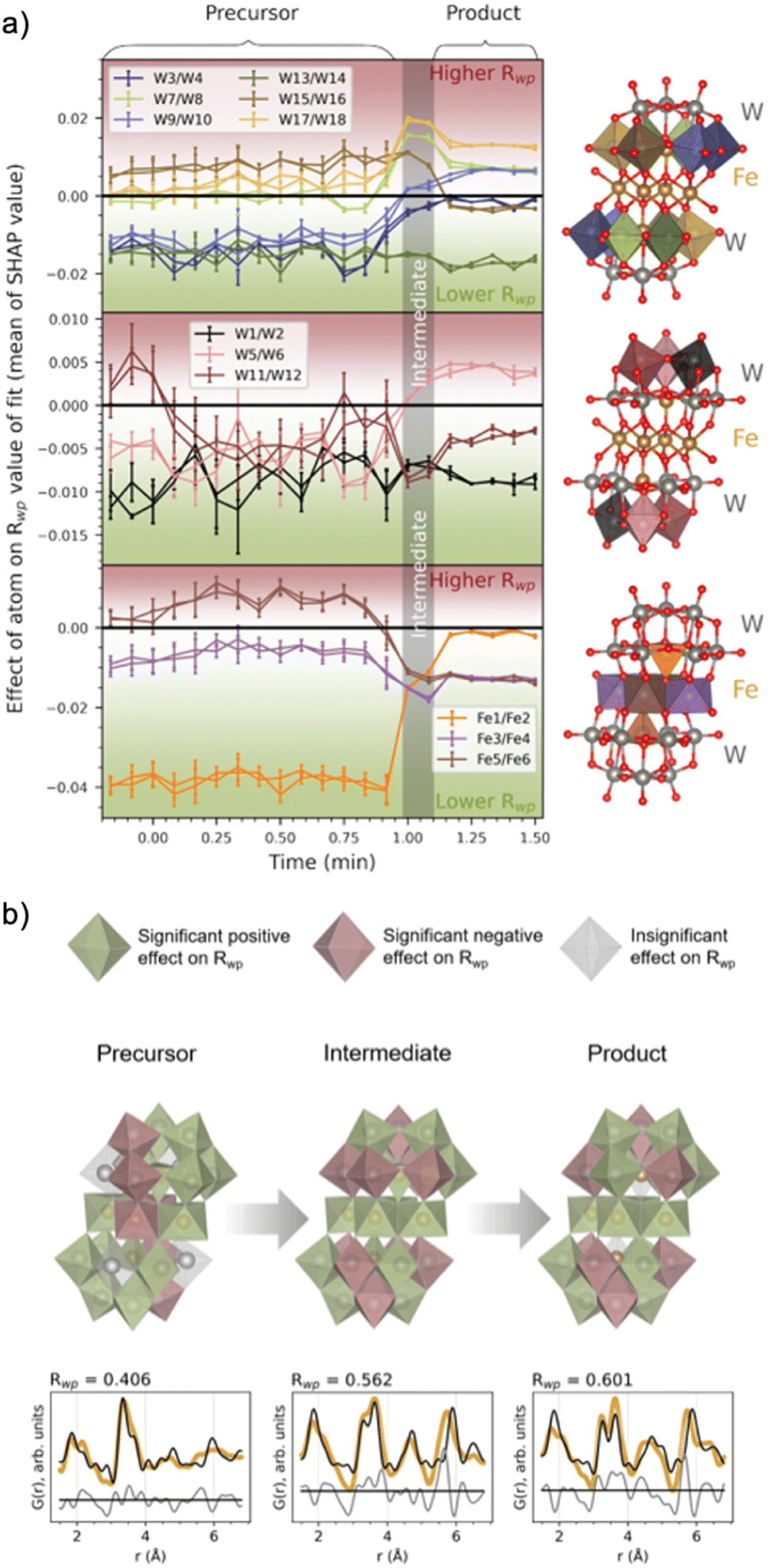 | ||
| Fig. 7 (a) The effect of a metal atom's presence in the structure, given as the mean and standard deviation (given as vertical lines for each mean) for each metal atom's SHAP values. The SHAP values are the output of the ML-MotEx algorithm, trained with fits to 10000 random fragments of the [Fe4(FeW9O34)2]16− cluster,20 for each PDF in the in situ series. The colour of the metal–oxygen polyhedra in the investigated structure is reflected in the colour of the plots (split into three segments for clarification). (b) The resulting cluster structures with fits for the precursor, intermediate and product phases after −0.17, 1.08 and 1.42 min of heating. Green and red polyhedra are deemed significant contributors to the fit by the ML algorithm, having a trending mean SHAP value below −0.001 or above +0.001, respectively. Grey polyhedra are deemed insignificant by the ML algorithm, with a trending mean SHAP value in the range of −0.001 to 0.001. Below each of the structures, fits to the data are shown, which includes only significant metal atoms contributing positively to the Rwp value (i.e. green atoms in the structures). The structure visualizations were performed with VESTA.24 | ||
The SHAP analysis shows several interesting trends, which are visualized at representative times for the precursor, intermediate, and product phases in Fig. 7b, where we use colour to indicate which polyhedron ML-MotEx wants to keep (green) or remove (red). We first consider the results for the precursor structure, i.e. before heating is initiated. Firstly, ML-MotEx seems to prefer W-triad units to be present (groups of three edge-sharing [WO6]10− octahedra). Secondly, the triad it prefers the most is located at the far edges of the cluster structure, skewed relative to one another along the bridging layer. Specifically, the mean SHAP values tend to be lower for the W atoms being the most skewed from the center of the cluster (W1–2, W3–4, W9–10, and W13–14). When examining the results from the intermediate and product stages of the reaction, this favouring of skewed W atoms is not present. Additionally, no triad units are preferred by ML-MotEx after the formation of the intermediate phase. As for Fe atoms, the tetrahedrally coordinated Fe atoms are strongly favoured in the precursor phase. The preference for tetrahedrally coordinated Fe atoms decreases when the intermediate phase forms, and in the product phase, ML-MotEx is indecisive about them. On the other hand, a full edge-sharing layer of octahedrally coordinated Fe atoms is preferred in the product. The presence of the full edge-sharing bridging layer corresponds well with the chains of edge-sharing metals present in the wolframite-type phase. Interestingly, the presence of both an edge-sharing bridging layer and tetrahedrally coordinated Fe atoms in the intermediate phase shows that this phase has characteristics from both the precursor and the product phase.
The favoured skewness of the precursor cluster initially seemed rather puzzling, which led us to search for other POMs with a higher degree of skewness. Such a structure was found in the ICSD database; a recently published structure with the formula (Ni6(H2O)9(OH)3(HSiW9O34))2(H2O)12 (ICSD Code 3561 (ref. 49)). The extracted cluster, after replacing Si and Ni with Fe and removing crystal water, has the formula (Fe6(FeW9O34))2. The cluster can be described as two Keggin fragments equal to the ones in the Fe–W sandwich cluster, but instead of being oppositely connected by the same bridging layer, this new POM has the two Keggin fragments connected to their own edge-sharing transition metal layer. These two layers are connected through corner-sharing. A visualization of this cluster, along with its fit to the FeWO4 precursor PDF, can be seen in Fig. 8. The PDF can be well described by this skewed cluster, showing that the less defined peaks over r ≈ 5 Å in the PDF are due to the less symmetrical structure of this cluster compared to the standard Tourné sandwich-type. It is also possible that the mixture consists of a broad range of clusters with structural similarities, where a single Keggin fragment [W9O34]14− is the only stable unit present. The CoWO4 and NiWO4 precursor phases can also be described by the skewed sandwich cluster, as seen in Fig. S11.† The Rwp value for these fits is slightly larger, due to the less defined PDFs of these phases.
 | ||
| Fig. 8 Fit of the skewed (Fe6(FeW9O34))2 cluster, stemming from the (Ni6(H2O)9(OH)3(HSiW9O34))2(H2O)12 structure to the FeWO4 precursor PDF. Zoom factor for the cluster related to the crystallographic directions of the parent crystal structure, scale factor, isotropic atomic displacement factors and δ2 were refined. | ||
The skewed cluster has a more equal amount between Fe/Co/Ni and W (nine W to every seven Fe/Co/Ni) compared to the Tourné-type sandwich cluster (nine W to every three Fe/Co/Ni). This cluster might therefore be promoted over the Tourné-type sandwich cluster in our mixtures, as the metal ratio in the precursor is equal to 1. The remaining free [FeO6]10− in the mixture, which are not incorporated in the model, can explain the peak at r ≈ 2.2 Å, which is not fully described in the fit. The paste-like appearance of the precursor mixtures points toward that these clusters are binding a lot of the water present, and that they are weakly bound to each other, forming amorphous particles.
Reaction mechanism
Fig. 9 summarizes the proposed reaction mechanism from amorphous precursors to crystalline MWO4. The precursor structure can be described as an amorphous mixture of weakly linked, skewed sandwich clusters. The intermediate phase has some similar characteristics to the precursor phase, including tetrahedrally coordinated Fe atoms (not shown in the figure). The degree of edge-sharing in the structure is the lowest in the intermediate phase, despite this being the transitioning state between a highly edge-sharing precursor with stable Fe bridging layers and a product with edge-sharing chains. This connects well to the breaking up of the W-triad units (groups of three edge-sharing [WO6]10− octahedra) in the Keggin fragments, proposed by the ML-MotEx algorithm (Fig. 7). Such a break-up is necessary to open for growth of the MWO4 structure if the edge-sharing Fe bridging layer is assumed to be stable. The intermediate phase can be described as disordered fragments with the MWO4 structure, with dominating growth in the b-direction. After a brief transition through this intermediate phase, growth will occur in all directions and an ordered MWO4 structure will form, where the metal atoms relax towards the edge of the octahedra, in the b-direction. | ||
| Fig. 9 Proposed reaction mechanism for the hydrothermal synthesis of MWO4. Growth directions are indicated by brown arrows. Skewed sandwich-clusters reorganize into chains of M–O and W–O octahedra, equivalent to the c-directions in the final MWO4 structure. Eventually, the structure will start growing in the other directions as well. The structure visualizations were performed with VESTA.24 | ||
The lower degree of ordering observed for the CoWO4 and NiWO4 precursor phases compared to the FeWO4 precursor phase gives us a clue regarding the reason these reactions do not form crystalline products like the FeWO4 reaction. A high degree of disorder in the precursor phases would naturally lead to a high degree of disorder in the intermediate phase, which ultimately leads to a larger crystallization barrier for the product phase.
Conclusions
Hydrothermal synthesis of wolframite-type MWO4 (M:Mn, Fe, Co, Ni) from soluble aqueous precursors has been investigated. Upon mixing of the aqueous precursors, a crystalline precursor formed for the MnWO4 synthesis, while amorphous pastes formed for the FeWO4, CoWO4 and NiWO4 syntheses, whose structures are distinct from those of the ions present in the individual precursor salt solutions. Upon heating, the crystalline MnWO4 precursor converted directly to a crystalline wolframite-type MnWO4 phase, while the remaining syntheses produced an intermediate phase. The FeWO4 intermediate phase eventually turned into a crystalline wolframite-type FeWO4 phase, while the CoWO4 and NiWO4 reactions halted after the formation of the intermediate phase.
Using database mining, it was concluded that the structure of the amorphous precursor pastes should include a Keggin fragment [W9O34]14−. The precursor material had some similarity to a Tourné sandwich-type, and by using this cluster as a starting structure, we analyzed its fit to the PDF using our algorithm ML-MotEx,32 which can be applied to determine the significance of individual structural features in a structure in a PDF fit. For PDFs of the amorphous precursor phase, ML-MotEx preferred W atoms giving a skewness of the cluster, and a significant presence of tetrahedrally coordinated Fe atoms. This led us to identify a skewed transition metal/tungsten oxide cluster which described the precursor PDF well. This skewed cluster had a more equal ratio between Fe and W atoms compared to the Tourné sandwich cluster, which is chemically reasonable considering the stoichiometry in the actual mixture.
The intermediate phase appearing after the amorphous precursors had many structural similarities with both the precursor and product phases. Our analysis showed a significant presence of tetrahedrally coordinated Fe atoms in the intermediate structure along with a strong presence of an edge-sharing bridging layer, despite the low edge-to corner-sharing intensity ratio observed at this point in the reaction. This led us to assume that there is a breaking up of W triad units in the Keggin fragments, which opens for growth of the structure. We found that the more disordered the precursor phase is, the longer the reaction time required to form crystalline products.
In summary, our work establishes the importance of polyoxometalates in the formation mechanisms of mixed metal oxides, and we provide an atomistic understanding of the process. By understanding how materials initially assemble in a solution, we are significantly closer to fully understanding how mixed metal oxides form.
Experimental methods
Chemical procedures
Four different precursor mixtures were prepared; 0.01 mol Na2WO4·2H2O dissolved in 5 mL deionized water was mixed with 0.01 mol metal chloride hydrate (MnCl2·4H2O, FeCl2·4H2O, CoCl2·6H2O, and NiCl2·6H2O) dissolved separately in 5 mL deionized water. This resulted in 1 M tungsten concentrations. The mixing happened under vigorous stirring and the resulting mixtures had a pH of 6 as measured with a HANNA HI 2020-02 pH meter. All the chemicals used were from Sigma-Aldrich and of ≥99% purity.In situ X-ray total scattering experiments
In situ total scattering experiments were performed on beamline P02.1 at PETRAIII, DESY in Hamburg, using an X-ray wavelength of 0.2072 Å (59.82 keV). The scattered X-rays were collected with a PerkinElmer 2D detector, positioned 216 mm away from the sample, typical for rapid acquisition PDF (RA-PDF) experiments.41In situ experiments were performed by injecting the prepared precursor mixtures into a fused silica capillary (inner and outer diameter of 0.70 and 0.88 mm, respectively), connected to Swagelok® tubing. The fused silica capillary was stabilized by a custom-built steel frame and the surrounding tubing was then pressurized to 100 bar and kept static using a standard high-performance liquid chromatography pump, similar to the setup of Becker et al.50 Rapid heating to 160 °C was initiated with a hot-air blower. It took ca. ∼90 s for the sample inside the capillary to reach the reaction temperature. Frames were collected with a time-resolution of 5 seconds/frame.Data treatment and PDF modelling
The collected total scattering data were integrated using PyFAI.51 Background subtraction, correction, normalization and Fourier transformation to PDFs31 were performed using PDFgetX3.52 The Fourier transformation was executed using the parameters Qmin = 1.2 Å−1, Qmax = 18 Å−1, Qmaxinst = 20 Å−1 and r-poly = 0.9 Å. The instrumental parameters were obtained from PDF analysis of a NIST CeO2 standard, giving a Qdamp of 0.043 Å−1 and a Qbroad of 0.021 Å−1. PDF modelling of precursor structures was performed in DiffPy-CMI,53 by fitting structures obtained from the Inorganic Crystal Structure Database (ICSD). Sequential fits of PDFs from the crystalline products were performed in reverse (starting with the last acquired frame) in PDFgui.54 Additional information about the modelling parameters and further analysis can be found in the ESI.†Ex situ syntheses and PXRD acquisition
The nanocrystalline intermediate phases of the CoWO4 and FeWO4 syntheses were synthesized using autoclaves and characterized ex situ. An identical precursor mixture as for the in situ experiments, but with a total volume of 10 mL, was prepared for both syntheses, before being transferred to 25 mL Teflon-lined stainless-steel autoclaves (40% filled autoclave). The autoclaves were then placed in an oven at 110 °C for 24 hours (corresponding to 1.3 bar autogenous pressure55,56). The heating rate in the autoclave was not measured and is unknown. After the autoclaves had cooled, the suspensions were washed twice with 40 mL of demineralized water and once with 40 mL of ethanol. After drying at room-temperature for two days in a crystallization dish, the powders were gently mortared. Ex situ PXRD data were collected with a Bruker D8 Discover using a Bragg–Brentano setup with a Cu Kα source (1.54 Å) and a LYNXEYE detector.Data availability
The data that support the findings of this study are available from the corresponding author upon reasonable request.Author contributions
S. L. S. and K. M. Ø. J. conceptualized the project. M. C. W., M. J., and T. L. C. performed the in situ experiments. S. L. S. performed the ex situ experiments. S. L. S. analyzed the data with input from A. S. A. and E. T. S. K. S. L. S., A. S. A., and K. M. Ø. J. wrote the original draft. All authors contributed to the review and editing of the paper. K. M. Ø. J. supervised the project.Conflicts of interest
There are no conflicts to declare.Acknowledgements
This work is part of a project that has received funding from the European Research Council (ERC) under the European Union's Horizon 2020 Research and Innovation Programme (grant agreement No. 804066). We are grateful to the Villum Foundation for financial support through a Villum Young Investigator grant. We furthermore thank DANSCATT (supported by the Danish Agency for Science and Higher Education) for support. Funding from the Danish Ministry of Higher Education and Science through the SMART Lighthouse is gratefully acknowledged. We acknowledge DESY (Hamburg, Germany), a member of the Helmholtz Association HGF, for the provision of experimental facilities. Parts of this research were carried out at beamline P02.1 at Petra III and we would like to thank Martin Etter for assistance in using the beamline.References
- E. D. Bojesen and B. B. Iversen, CrystEngComm, 2016, 18, 8332–8353 RSC.
- D. Gebauer, A. Völkel and H. Cölfen, Science, 2008, 322, 1819–1822 CrossRef CAS PubMed.
- R. Demichelis, P. Raiteri, J. D. Gale, D. Quigley and D. Gebauer, Nat. Commun., 2011, 2, 1–8 Search PubMed.
- D. Gebauer and H. Cölfen, Nano Today, 2011, 6, 564–584 CrossRef CAS.
- J. Ke, M. A. Younis, Y. Kong, H. Zhou, J. Liu, L. Lei and Y. Hou, Nano-Micro Lett., 2018, 10, 1–27 CrossRef PubMed.
- H. Jia, J. Stark, L. Qin Zhou, C. Ling, T. Sekito and Z. Markin, RSC Adv., 2012, 2, 10874–10881 RSC.
- M. G. Joaquín-Morales, A. F. Fuentes, S. M. Montemayor, M. J. Meléndez-Zaragoza, J. M. S. Gutiérrez, A. L. Ortiz and V. Collins-Martínez, Int. J. Hydrogen Energy, 2019, 44, 12390–12398 CrossRef.
- C. Liu, H. Lü, C. Yu, X. Wu and P. Wang, Mater. Lett., 2019, 257, 126707 CrossRef CAS.
- S. Rajagopal, D. Nataraj, O. Y. Khyzhun, Y. Djaoued, J. Robichaud and D. Mangalaraj, J. Alloys Compd., 2010, 493, 340–345 CrossRef CAS.
- J. Tian, Y. Xue, X. Yu, Y. Pei, H. Zhang and J. Wang, RSC Adv., 2018, 8, 417470 Search PubMed.
- M. Juelsholt, T. L. Christiansen and K. M. Ø. Jensen, J. Phys. Chem. C, 2019, 123, 5110–5119 CrossRef CAS.
- E. D. Bøjesen, K. M. Ø. Jensen, C. Tyrsted, A. H. Mamakhel, H. L. Andersen, H. Reardon, J. Chevalier, A.-C. Dippel and B. B. Iversen, Chem. Sci., 2016, 7, 6394–6406 RSC.
- M. Ammam, J. Mater. Chem. A, 2013, 1, 6291–6312 RSC.
- N. I. Gumerova, A. Rompel and U. Wien, Chem. Soc. Rev., 2020, 49, 7568–7601 RSC.
- M. Hutin, M. H. Rosnes, D. Long and L. Cronin, Compr. Inorg. Chem. II, 2013, 2, 241–269 CAS.
- D. L. Long, R. Tsunashima and L. Cronin, Angew. Chem., Int. Ed., 2010, 49, 1736–1758 CrossRef CAS PubMed.
- X. López, J. J. Carbó, C. Bo and J. M. Poblet, Chem. Soc. Rev., 2012, 41, 7537–7571 RSC.
- M. Nyman and P. C. Burns, Chem. Soc. Rev., 2012, 41, 7354–7367 RSC.
- O. Sadeghi, L. N. Zakharov and M. Nyman, Science, 2015, 347, 1359–1362 CrossRef CAS PubMed.
- E. M. Limanski, M. Piepenbrink, E. Droste, K. Burgemeister and B. Krebs, J. Cluster Sci., 2002, 13, 369–379 CrossRef CAS.
- C. M. Tourné, G. F. Tourné and F. Zonnevijlle, J. Chem. Soc., Dalton Trans., 1991, 143–155 RSC.
- D. Barats, G. Leitus, R. Popovitz-Biro, L. J. W. Shimon and R. Neumann, Angew. Chem., Int. Ed., 2008, 47, 9908–9912 CrossRef CAS PubMed.
- A. R. Kampf, J. M. Hughes, B. P. Nash, S. E. Wright, G. R. Rossman and J. Marty, Am. Mineral., 2014, 99, 1045–1051 CrossRef.
- K. Momma and F. Izumi, J. Appl. Crystallogr., 2011, 44, 1272–1276 CrossRef CAS.
- P. J. Chupas, K. W. Chapman, G. Jennings, P. L. Lee and C. P. Grey, J. Am. Chem. Soc., 2007, 129, 13822–13824 CrossRef CAS PubMed.
- D. S. Cook, Y. Wu, K. Lienau, R. Moré, R. J. Kashtiban, O. V. Magdysyuk, G. R. Patzke and R. I. Walton, Chem. Mater., 2017, 29, 5053–5057 CrossRef CAS.
- O. G. Grendal, I. E. Nylund, A. B. Blichfeld, S. Tominaka, K. Ohara, S. M. Selbach, T. Grande and M. A. Einarsrud, Chem. – Eur. J., 2020, 26, 9348–9355 CrossRef CAS PubMed.
- K. M. Ø. Jensen, M. Christensen, P. Juhas, C. Tyrsted, E. D. Bøjesen, N. Lock, S. J. L. Billinge and B. B. Iversen, J. Am. Chem. Soc., 2012, 134, 6785–6792 CrossRef CAS PubMed.
- T. Lindahl Christiansen, E. T. S. Kjær, A. Kovyakh, M. L. Röderen, M. Høj, T. Vosch and K. M. Ø. Jensen, J. Appl. Crystallogr., 2020, 53, 148–158 CrossRef CAS PubMed.
- C. Tyrsted, K. M. Ørnsbjerg Jensen, E. D. Bøjesen, N. Lock, M. Christensen, S. J. L. Billinge and B. Brummerstedt Iversen, Angew. Chem., Int. Ed., 2012, 51, 9030–9033 CrossRef CAS PubMed.
- T. Lindahl Christiansen, S. R. Cooper and K. M. Ø. Jensen, Nanoscale Adv., 2020, 13, 8725–8735 Search PubMed.
- A. S. Anker, E. T. S. Kjær, M. Juelsholt, T. L. Christiansen, S. L. Skjærvø, M. R. V. Jørgensen, I. Kantor, D. R. Sørensen, S. J. L. Billinge, R. Selvan and K. M. Ø. Jensen, npj Comput. Mater., 2022, 8, 213 CrossRef.
- S. M. Lundberg, G. Erion, H. Chen, A. DeGrave, J. M. Prutkin, B. Nair, R. Katz, J. Himmelfarb, N. Bansal and S.-I. Lee, Nat. Mach. Intell., 2020, 2, 56–67 CrossRef PubMed.
- S. M. Lundberg and S.-I. Lee, Proceedings of the 31st International Conference on Neural Information Processing Systems, 2017, pp. 4765–4774 Search PubMed.
- G. He, J. Li, W. Li, B. Li, N. Noor, K. Xu, J. Hu and I. P. Parkin, J. Mater. Chem. A, 2015, 3, 14272–14278 RSC.
- S. Jha, S. Mehta, E. Chen, S. S. Sankar, S. Kundu and H. Liang, Mater. Adv., 2020, 1, 2124–2135 RSC.
- N. L. M. Tri, D. S. Duc, D. Van Thuan, T. A. Tahtamouni, T. D. Pham, D. T. Tran, N. Thi Phuong Le Chi and V. N. Nguyen, Chem. Phys., 2019, 525, 1–7 CrossRef.
- X. X. Wang, Y. Li, M. C. Liu and L. B. Kong, Ionics, 2018, 24, 363–372 CrossRef CAS.
- J. Macavei and H. Schulz, Z. Kristallogr. – New Cryst. Struct., 1993, 207, 193–208 CrossRef CAS.
- D. Ülkü, Z. Kristallogr. – New Cryst. Struct., 1967, 124, 192–219 Search PubMed.
- P. J. Chupas, X. Qiu, J. C. Hanson, P. L. Lee, C. P. Grey and S. J. L. Billinge, J. Appl. Crystallogr., 2003, 36, 1342–1347 CrossRef CAS.
- L. Niu, Z. Li, Y. Xu, J. Sun, W. Hong, X. Liu, J. Wang and S. Yang, ACS Appl. Mater. Interfaces, 2013, 5, 8044–8052 CrossRef CAS PubMed.
- M. I. Ahmed, A. Adam, A. Khan, A. U. Rehman, M. Qamaruddin, M. N. Siddiqui and M. Qamar, Mater. Lett., 2016, 183, 281–284 CrossRef CAS.
- H. Feng, Y. Xi and Q. Huang, Dalton Trans., 2020, 49, 12242–12248 RSC.
- H. Weitzel, Z. Kristallogr. – Cryst. Mater., 1976, 144, 238–258 CrossRef.
- S. J. Angus-Dunne, J. A. Irwin, R. C. Burns, G. A. Lawrance and D. C. Craig, J. Chem. Soc., Dalton Trans., 1993, 1993, 2717–2726 RSC.
- E. T. S. Kjær, O. Aalling-Frederiksen, L. Yang, N. K. Thomas, S. J. L. Billinge and K. M. Ø. Jensen, Chem. Methods, 2022, 2, e202200034 Search PubMed.
- K. G. Burtseva, T. S. Chernaya and M. I. Sirota, Akad. Nauk SSSR, 1978, 243, 104–107 CAS.
- X.-M. Luo, L. Chen, Y.-Y. Dong, J. Li, C.-H. Cui, J.-P. Cao and Y. Xu, Dalton Trans., 2018, 47, 9504–9511 RSC.
- J. Becker, M. Bremholm, C. Tyrsted, B. R. Pauw, K. M. Ø. Jensen, J. Eltzholtz, M. Christensen and B. B. Iversen, J. Appl. Crystallogr., 2010, 43, 729–736 CrossRef CAS.
- G. Ashiotis, A. Deschildre, Z. Nawaz, J. P. Wright, D. Karkoulis, F. E. Picca and J. Kieffer, J. Appl. Crystallogr., 2015, 48, 510–519 CrossRef CAS PubMed.
- P. Juhás, T. Davis, C. L. Farrow and S. J. L. Billinge, J. Appl. Crystallogr., 2012, 46, 560–566 CrossRef.
- P. Juhás, C. L. Farrow, X. Yang, K. R. Knox and S. J. L. Billinge, Acta Crystallogr., Sect. A: Found. Crystallogr., 2015, 71, 562–568 CrossRef PubMed.
- C. L. Farrow, P. Juhas, J. W. Liu, D. Bryndin, E. S. Božin, J. Bloch, P. Th and S. J. L. Billinge, J. Phys.: Condens. Matter, 2007, 19, 335219 CrossRef CAS PubMed.
- A. Rabenau, Angew. Chem., Int. Ed., 1985, 24, 1026–1040 CrossRef.
- R. I. Walton, Chem. Soc. Rev., 2002, 31, 230–238 RSC.
Footnote |
| † Electronic supplementary information (ESI) available. See DOI: https://doi.org/10.1039/d3sc00426k |
| This journal is © The Royal Society of Chemistry 2023 |