
 Open Access Article
 This Open Access Article is licensed under a Creative Commons Attribution-Non Commercial 3.0 Unported Licence
Assigning 1H chemical shifts in paramagnetic mono- and bimetallic surface sites using DFT: a case study on the Union Carbide polymerization catalyst†
Anna Giorgia
Nobile
a,
David
Trummer
a,
Zachariah J.
Berkson
a,
Michael
Wörle
a,
Christophe
Copéret
 *a and
Pierre-Adrien
Payard
*ab
*a and
Pierre-Adrien
Payard
*ab
aETH Zürich Department of Chemistry and Applied Biosciences, Vladimir-Prelog-Weg 2, CH-8093 Zürich, Switzerland. E-mail: ccoperet@ethz.ch; pierre-adrien.payard@univ-lyon1.fr
bUniversité de Lyon, Université Claude Bernard Lyon I, CNRS, INSA, CPE, UMR 5246, ICBMS, Rue Victor Grignard, F-69622 Villeurbanne Cedex, France
First published on 2nd February 2023
Abstract
The Union Carbide (UC) ethylene polymerization catalyst, based on silica-supported chromocene, is one of the first industrial catalysts prepared by surface organometallic chemistry, though the structure of the surface sites remains elusive. Recently, our group reported that monomeric and dimeric Cr(II) sites, as well as Cr(III) hydride sites, are present and that their proportion varies as a function of the Cr loading. While 1H chemical shifts extracted from solid-state 1H NMR spectra should be diagnostic of the structure of such surface sites, unpaired electrons centered on Cr atoms induce large paramagnetic 1H shifts that complicate their NMR analysis. Here, we implement a cost-efficient DFT methodology to calculate 1H chemical shifts for antiferromagnetically coupled metal dimeric sites using a Boltzmann-averaged Fermi contact term over the population of the different spin states. This method allowed us to assign the 1H chemical shifts observed for the industrial-like UC catalyst. The presence of monomeric and dimeric Cr(II) sites, as well as a dimeric Cr(III)-hydride sites, was confirmed and their structure was clarified.
1. Introduction
Polyethylene (PE) is one of the most commonly used plastics with an annual production exceeding 100 million tons.1 Its manufacture relies mostly on Ziegler-Natta or Phillips catalysts, involving paramagnetic Ti(III) and Cr(III) active sites.1–3 Another notable example is the Union Carbide (UC) catalyst, based on silica-supported chromocene CrIICp2 (1), that has been used for specialized applications.4–6 The nature of its surface and active sites has been under investigation for more than 50 years due to the complexity of this system, though various types of Cr sites have been proposed based on IR and solid-state NMR spectroscopic analyses.5,7–9 For example, we have recently investigated the effect of the Cr loading on the IR response after CO adsorption in the UC catalyst. Complemented with detailed computational studies, it was possible to identify mono-grafted Cr(II) sites I as well as dimeric Cr(II) sites with weak (III) and strong (II) Cr–Cr interactions (Fig. 1A).10 At high Cr loading (1 and 2 wt% Cr), we reported that dimeric and monomeric Cr(III)-hydrides (IV and V) are likely present, as evidenced by the appearance of low energy CO bands, indicative of Cr-formyl species formed upon CO insertion into a Cr-hydride bond. The formation of these sites is supported by DFT studies and their presence was identified by EPR spectroscopy and labeling studies. This study also indicated that the active sites are more likely to be monomeric Cr(III) sites, consistent with what was found in corresponding molecular systems.11,12 | ||
| Fig. 1 (A) Identified surface sites in the UC catalyst as a function of the Cr loading based on CO-IR and EPR spectroscopy as well as DFT studies, as outlined in our previous work.10 The numbering of the surface species has been adapted accordingly. At low Cr loading, monomeric Cr(II) sites I are mainly present; these sites can possibly interact with residual surface OH groups (vide infra). When increasing the Cr loading, site I can interact with 1 to form dimeric sites with a bridging Cp ligand (III) or direct Cr–Cr interaction (II). Site II can yield a bridging Cr(III)-hydride complex (IV) via C–H activation at the Cp ring, which can further react with a surface hydroxyl group, leading to a monomeric Cr(III) hydride (V). (B) A mono-grafted Cr site and dimeric Cr(III) and Cr(II) surface sites were identified by Schnellbach et al. using temperature-dependent 1H MAS NMR spectroscopy.19 | ||
With these results in hand, we decided to re-investigate the speciation of surface sites using solid-state NMR spectroscopy, used in pioneering studies on understanding the Cr-site structure.13 The advantage of this technique over IR spectroscopy is its high spectral resolution without the need for probe molecules that can influence or modify the surface site distributions and structures. However, the presence of unpaired electrons in Cr-based sites introduces additional complexity that impedes a straightforward interpretation of NMR spectra. Indeed, the interaction of unpaired electrons with nuclear spins yields so-called paramagnetic chemical shifts that can appear in a broad range and that are impossible to predict by way of basic qualitative reasoning.14–17 This makes the assignment of paramagnetically shifted signals exceptionally challenging, especially in the case of multimeric sites and antiferromagnetically coupled Cr atoms. While computational protocols have been optimized to calculate paramagnetic chemical shifts in the case of monomeric metal complexes,14,18 no work has been reported in the case of dimeric complexes to the best of our knowledge.
Previous 1H solid-state magic-angle-spinning (MAS) NMR studies on the UC catalyst at low Cr loading highlighted the presence of two signals consistent with surface-attached chromium species around 282 ppm and 25 ppm.13 At higher Cr loadings, it was reported that the signal intensity of the peak at 282 ppm decreases with the appearance of a new resonance at 148 ppm. Furthermore, it was reported that the signal at 282 ppm shows a higher chemical shift upon lowering the temperature, while the signals at 148 ppm and 25 ppm are insensitive to temperature changes.13 Based on these findings, the signal at 282 ppm was assigned to a mono-grafted chromium site, while the resonances at 148 ppm and 25 ppm to dimeric Cr(III) and Cr(II) sites respectively (Fig. 1B).
In this work, we first investigated the effect of the Cr loading on the 1H MAS NMR signatures of 1 supported on SiO2–700 to parallel what we have recently carried out with IR spectroscopy.20 Next, we optimized a computational approach to evaluate the chemical shift of weakly interacting spins in bimetallic complexes. More precisely, the chemical shift was calculated using a Boltzmann distribution of the Fermi contact terms averaged over the different spin states, calculated using a DFT methodology inspired by Rastrelli and Bagno.14,21 The spin–spin coupling constant J, which determines the splitting of the spin states, was estimated using the broken symmetry approach.22 This methodology was benchmarked on a series of paramagnetic metal monomers and dimers and later on used to decipher the structure of surface sites by assigning paramagnetic-shifted 1H MAS NMR signals of the industrial-like UC catalyst at various Cr loadings.
2. Results and discussion
2.1. 1H chemical shifts in the industrial-like UC catalyst
The industrial-like UC catalyst was prepared by reacting chromocene CrCp2 (1) with silica, partially dehydroxylated at 700 °C, according to our previously reported procedure.10 The catalyst was prepared with four different Cr loadings: 0.25, 0.5, 1.0, and 2.0 wt% Cr, yielding respectively 1-SiO2-0.25, 1-SiO2-0.5, 1-SiO2-1, and 1-SiO2-2. The solid-state 1H MAS NMR spectra were acquired at 16.4 T (700 MHz for 1H), in flowing dry N2 gas, and a temperature of 280 K. In addition, the temperature dependence of the NMR signals was investigated by recording spectra at 293, 273, and 253 K. 1H MAS rates of 35 and 40 kHz were used to minimize the overlap of paramagnetic shifted 1H signals and spinning sidebands.23 For each sample, three 1H MAS NMR spectra with different center frequencies of 300 ppm, 150 ppm, and 0 ppm were recorded to detect the different paramagnetic-shifted signals.The 1H MAS NMR spectrum of 1-SiO2-1 in Fig. 2 shows a substantial sideband manifold, consistent with large 1H chemical shift anisotropies associated with the paramagnetic nature of surface Cr sites.13,15,24 Besides the spinning sidebands, the 1H MAS NMR spectrum of 1-SiO2-1 shows a weak, highly deshielded signal at 318 ppm, together with a more intense signal around 155 ppm. The latter disappears after long acquisition times (∼days) regardless of the temperature of the measurement, indicating the sensitivity of the associated surface species. Besides the two highly de-shielded signals, two additional peaks close to the diamagnetic region appear at 23 ppm and 12 ppm, as previously reported.13 In the diamagnetic region, the peaks at 2.1 ppm and 4.3 ppm are associated with the isolated and interacting OH groups of the silica surface25 and the one at 6.7 ppm with a trace amount of cyclopentadiene adsorbed on silica, similar to what is observed for pentamethylcyclopentadiene.26
 | ||
| Fig. 2 1D relaxation-resolved 1H MAS NMR echo spectrum of 1-SiO2-1 acquired at 35 kHz MAS, 16.4 T, 0.005 s recycle delay, and a temperature of 280 K measured in the gas stream near the NMR rotor. The paramagnetic peaks are shown in blue, whereas the spinning sidebands and a background signal are indicated by “*” and “#” symbols, respectively. The blue arrows show the shift of the peaks upon cooling to 240 K. The peaks at 2.1, 4.3, and 6.7 ppm are indicative of isolated and interacting OH groups and trace amounts of cyclopentadiene adsorbed on silica respectively. | ||
Regarding temperature dependence, the most de-shielded peak at 318 ppm shifts downfield while cooling below room temperature (ΔT = −40 K and Δδ = +46 ppm). The peak at 155 ppm also shifts downfield while cooling below room temperature, but with a less pronounced temperature dependence (ΔT = −40 K and Δδ = +16 ppm) that is also indicative for monomeric sites, as reported by Schnellbach13 (see Fig. S6† for details). In contrast to the highly de-shielded resonances, the two peaks close to the diamagnetic region shift slightly up-field upon cooling below room temperature: ΔT = −40 K and Δδ = −3 (peak at 23 ppm) and −2 (peak at 12 ppm) as shown in Fig. S6.†
2.2. Effect of the Cr loading
To further investigate the attribution of the various resonances to specific surface sites, we next investigated the 1H MAS NMR spectra of UC-like catalysts with different Cr loadings. In the 1H MAS NMR spectrum of 1-SiO2-0.25 (0.25 wt% Cr loading), only two highly de-shielded resonances at 318 ppm and 155 ppm (Fig. S4†) are observed. Based on our previous CO-IR investigation,10 this material mainly consists of monomeric Cr(II) sites I (Fig. 1). In addition, these peaks shift down-field upon cooling and are therefore consistent with monomeric sites or potentially dimeric Cr(II) sites with weak Cr–Cr interactions. This could result from the interaction between I and adsorbed chromocene (site III). Alternatively, we could expect an interaction between some of the Cr centers of I and nearby surface OH groups I-OH.When increasing the Cr loading to 0.5 wt% (1-SiO2-0.5, Fig. S5†), two additional resonances appear at 22 ppm and 13 ppm (see Fig. 3). For 1-SiO2-1 and 1-SiO2-2, no additional resonances appear; however, the peak at 13 ppm gains in intensity compared to the peak at 22 ppm (see Fig. 3 and S6†). The appearance of these less deshielded signals parallels the formation of dimeric sites such as II, as evidenced earlier by CO-IR investigations.20 The slightly up-field shift upon cooling is also consistent with the presence of dimeric sites. The increase in intensity at 13 ppm at higher loading matches with the appearance of the low energy CO bands in IR, which we assigned to monomeric and dimeric Cr(III)-hydride sites (V and IV respectively).10
 | ||
| Fig. 3 Evolution of 1H MAS NMR signal intensities in the diamagnetic region as a function of the Cr loading. A background signal in 1-SiO2-0.25 is indicated by “#”. While both peaks are absent in 1-SiO2-0.25, the signal at 13 ppm significantly increases in intensity by increasing the Cr loading (1-SiO2-2). | ||
2.3. Paramagnetic proton shifts of monomeric and dimeric molecular complexes
After having qualitatively assigned the proton shifts based on our previous proposed structures and their temperature-dependent behavior, we next calculated the respective 1H shifts to corroborate their assignment and determine the structural features of the specific surface sites. Towards this goal, we first evaluated the accuracy of the proposed calculation methodologies to predict the chemical shifts of Cp ligands by using 1 and [(CpCrIIOtBu)2] (2) as molecular models for monomeric and dimeric sites.Experimentally, chromocene (1) is characterized by a peak at 325 ppm at room temperature in d8-toluene (see Fig. S7†). When lowering the temperature to 253 K, the signal shifts down-field to 383 ppm (Fig. S7†). The 1H shift follows an inverse temperature dependence (Fig. S10†) in the temperature range from 323–238 K. Using the expression of the Fermi contact term (see the section Methodology and computational details), the hyperfine coupling constant was fitted to A = 5.0 MHz (assuming g = ge = 2, Fig. S10†). A hyperfine coupling constant A of 3.8 MHz is predicted by DFT. From eqn (6), the 1H resonance of 1 at 293 K is expected at 301 ppm with a down-field shift to 341 ppm at 253 K. This is in good agreement with the experimentally observed behavior, indicating that this approach is suitable for estimating the paramagnetic 1H shifts of monomeric chromocene-based complexes.
With the dimeric [(CpCrIIOtBu)2] complex 2, we evaluate the method for 1H shift calculations in the presence of electronic spin–spin interactions. The 1H NMR spectrum of 2 shows a shift at 40 ppm corresponding to the H of the Cp ligand at room temperature in d8-toluene. This signal moves up-field to 2 ppm (δ = −38 ppm) when cooled at 253 K (Fig. 4A). This effect originates from the electronic structure of complex 2, where each CrII center is in a local high spin state (S = 2, see Table S3†) and the weak spin–spin interaction between the two creates five global spin states (S = 0, 1, 2, 3, and 4).
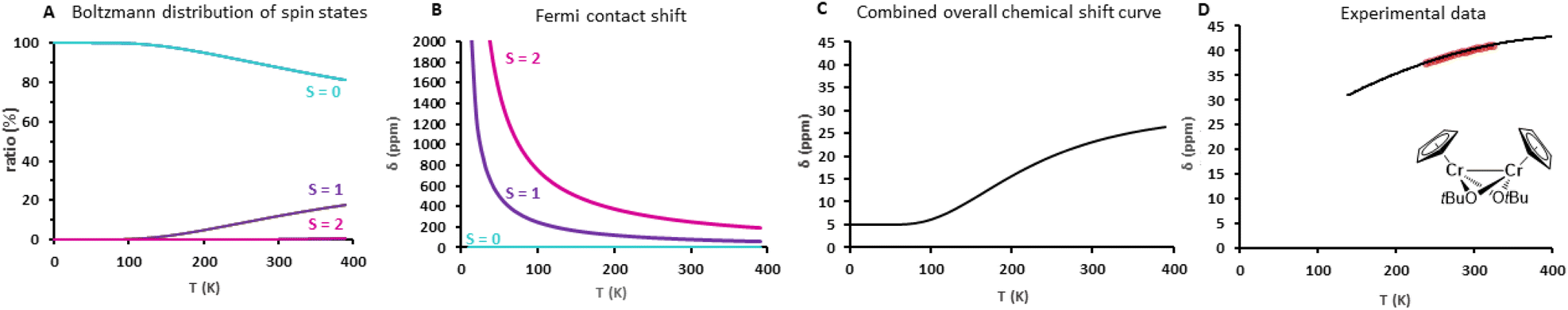 | ||
| Fig. 4 Illustration of the different contributions to the chemical shift of complex 2. The calculated combined overall chemical shift curve in (C) results from a linear combination of the Boltzmann distribution of spin states (A) and the Fermi contact shifts δFC of the global spin states, as visualized in (B). For 2, a slight decrease in the chemical shift is expected while cooling below room temperature. The experimental data shown in (D) agree with the calculated 1H shift curve of (C). | ||
These states split energetically as follows:
| ES = S(S + 1)J | (1) |
 | (2) |
The chemical shift calculated according to eqn (2) contains a double temperature dependence: the inverse temperature dependence of the Fermi contact shift for each global spin state, as well as the population of global spin states according to the Boltzmann distribution. For simplicity reasons, the hyperfine constant A between nuclear and electronic spins was calculated for the global high spin complex and is assumed to be constant for all other spin states (see Table S6†). Fig. 4C displays the 1H shift curve of 2 as a combination of the Boltzmann distribution (Fig. 4A) and the individual Fermi contact shift curves (Fig. 4B) of the global spin states (S = 0 to 2 were considered). The predicted 1H shift curve (18 ppm, 293 K, Fig. 4C) is in reasonable agreement with the experimental data obtained in a smaller temperature interval (40 ppm, 293 K, d8-toluene, see Fig. 4D). Although the calculated 1H chemical shift is slightly underestimated, the temperature dependence is nicely reproduced. This difference could be due to an underestimation of the S = 1 population, because of a slightly elongated Cr–Cr bond distance in solution for instance. Indeed, the Cr–Cr bond distance strongly impacts the spin population and thus the chemical shift behavior. Fig. S14† illustrates the effect of changes in the global spin state populations on the shape of the 1H shift curve of 2 when elongating the Cr–Cr distance. As seen from the J constant, the population of higher global spin states is favored at room temperature when the interatomic distance increases. An increase in the Cr–Cr distance by 0.25 Å (see ESI Section 4.3.3 and Fig. S14† for more details) can already cause an inversion in the temperature dependence of the chemical shift curve when cooling below room temperature. From these results, we can probably attribute the small deviations between the measured and calculated chemical shifts to a small difference in the Cr–Cr distance between the crystal structure and the actual complex in solution (or on the surface).
The applicability of this method was then evaluated on a consistent series of dimeric complexes [CpCrX2 or 3]2 (see Table 1). For the calculations of all molecular complexes in this work, the crystal structures of the complexes were used and only the hydrogen position was optimized. The experimental trend is nicely reproduced with an increase in the 1H shift with increasing interatomic distance.
Overall, this methodology shows that the paramagnetic contribution to the 1H chemical shielding primarily depends on the strength of the Cr–Cr interactions. Thus, the chemical shift is a direct descriptor of the spin state of the dimer and the Cr–Cr distance can be deducted a posteriori from the 1H shift.
2.4. Method validation and applicability
We applied the aforedescribed methodology for calculating the 1H shifts of monomeric and dimeric sites on a set of paramagnetic monomeric and dimeric complexes based on 3d transition metals. For these calculations, we used the crystal structure of each complex and only optimized the proton positions (Fig. 5, see Table S3† for the references and experimental 1H chemical shifts, Section S1† for the synthesis procedure of [Cp2Cr], [(Cp2Cr2(OSi(OtBu)3)2)] and [(Mes)2Co]2 and S2.1† for the synthesis procedure and crystallographic details of [(Cp2Cr2(OSi(OtBu)3)3)+(Cp3Cr2(OSi(OtBu)3)4)−]). An overall good agreement (R2 = 0.969 and slope = 1.014) is obtained between experimental and theoretical data. Given the complexity of the interpretation of paramagnetic shifts, this good agreement shows that the developed methodology can be useful for structure elucidation using NMR spectroscopy of paramagnetic complexes, regardless of the spin state or nuclearity. In fact, this method was also used on a reported Fe dimer,19 where we would propose to re-assign the spectral interpretation based on the calculations (see Table S4 and Fig. S9†). | ||
| Fig. 5 (A) Monomeric and dimeric molecular complexes are included in the validation set. The proton chemical shift of the –CH2– of [Cp*Cr(CH2SiMe3)2] and [Cp*Cr(CH2SiMe3)2(THF)] is not reported bottom. (B) Experimental vs. calculated 1H shifts at 293 K. The blue and green dots correspond to monomeric and dimeric molecular complexes respectively. The dashed black line represents x = y. The correlation coefficient R2 for monomeric and dimeric complex datasets is R2 = 0.996 and R2 = 0.925 respectively. For the evaluation of the choice of the basis set see Section 4.1 in the ESI.† | ||
2.5. Assigning 1H chemical shifts in the UC catalyst
As stated before, in the low-Cr-loading catalyst 1-SiO2-0.25, only two highly deshielded resonances at 318 ppm and 155 ppm are observed. According to our previous studies, this material mainly presents monomeric surface sites similar to the model site I (S = 2). Calculating the proton resonance of CpCrOSi(OH)3 free of interaction with the surface would predict a chemical shift of 549 ppm, while including an additional interacting oxygen ligand from a nearby Si–O–Si bridge, such as in I-OH, predicts a 1H shift at 184 ppm, which is close to the experimentally observed peak at 155 ppm, as shown in Fig. 6. Furthermore, these calculations predict a down-field shift to 208 ppm at 253 K, which is in the range of the experimentally observed shift from 155 ppm at 293 K to 171 ppm at 253 K for this peak. Thus, the peak at 155 ppm is best assigned to I-OH: an isolated, mono-grafted chromocene interacting with adjacent siloxane bridges from the silica surface (see Section 4.1.1 and Fig. S12†). | ||
| Fig. 6 1H MAS-NMR spectrum of 1-SiO2-1 acquired at 40 kHz MAS, 16.4 T, and a temperature of 280 K measured in the gas stream near the NMR rotor. Spinning sidebands and a background signal are indicated by “*” and “#” symbols, respectively. The paramagnetic-shifted 1H signals are assigned to monomeric sites interacting with nearby Si–O–Si bridges from the silica surface (155 ppm, red), as well as dimeric sites with strong (II, 22 ppm (green) and 13 ppm (orange)) and weak (III, 318 ppm, blue) Cr–Cr interactions. The presence of trace amounts of 1 strongly adsorbed on silica (318 ppm) cannot be excluded. C–H activated Cr(III)-hydrides (IV) appear at 13 ppm and are overlapping with the strongly interacting 1 unit of site II. The signals at 2.1–4.3 ppm and 6.7–7.5 ppm in the diamagnetic region are assigned respectively to isolated (2.1 ppm) and interacting (3.2 ppm and 4.3 ppm) surface hydroxyl groups, and trace amounts of physisorbed dicyclopentadiene (6.7–7.5 ppm). | ||
Note that the 1H shift of chromocene is calculated to be 301 ppm as discussed above, which is quite close to the experimentally observed peak at 318 ppm in the 1H MAS-NMR spectrum (see Fig. 6), likely indicating the presence of strongly adsorbed chromocene on silica. However, a similar chemical shift is expected for site III (dimeric Cr(II) sites with weak Cr–Cr interactions), with a 1H shift of 302 ppm for the Cp ligand located on the grafted Cr (marked in blue in Fig. 6).
The nearby weakly interacting chromocene unit of site III is expected at 1134 ppm assuming rapid exchange between the two Cp moieties. This signal is not observed experimentally, most likely due to the fast relaxation and the associated peak broadening (see Fig. S15† for details). Thus, the experimentally observed peak at 318 ppm is most consistent with dimeric sites such as site III. However, the presence of trace amounts of strongly adsorbed chromocene 1 on silica cannot be excluded.
As represented in the calculated 1H shift curve of site II with strong Cr–Cr interactions (see Fig. S13†), calculations predict two peaks at 21 ppm for the “grafted part” (in green) and 15 ppm for the average of all protons of the strongly interacting chromocene unit (in orange), where all the protons can be considered equivalent (see Fig. S13†). Regarding temperature dependence, calculations predict an up-field shift of 2 ppm for the peak at 23 ppm (293 K) and 1 ppm for the peak at 13 ppm (293 K) while cooling to 253 K. These findings agree with the experimental data and the up-field shift of 3 ppm (for the peak at 22 ppm) and 2 ppm (for the peak at 13 ppm) while cooling to 253 K. Details on the calculation of the chemical shift curves for site II are outlined in ESI Section 4.4.2.†
For surface site IV, the protons from different Cp ligands are considered all similar with a predicted average 1H shift around 7 ppm that is almost insensitive upon temperature variation. When considering the Cp ligands separately, similar results are obtained (see Fig. S16†). The fact that the intensity of the experimentally observed peak at 13 ppm increases significantly with the Cr loading (see ESI Section 4.4.5 and Fig. S16†) is consistent with the presence of an additional dimeric surface site such as IV, as proposed to be present in 1-SiO2-1 and 1-SiO2-2. The bridging hydride is expected at −5 ppm although not resolved experimentally likely due to low signal intensity, fast relaxation, and potential overlap with the very intense diamagnetic 1H resonances of the surface hydroxyl groups. The 1H resonance of the proposed active site structure V (Fig. 1), which is expected at 229 ppm, is not observed experimentally due to its low abundance (1–3%).
3. Conclusions
In this work, we recorded the 1H MAS NMR of Union Carbide catalysts at various Cr loadings and developed a computational methodology to calculate the 1H NMR chemical shifts of weakly coupled dimeric complexes. This method takes into account the Boltzmann-averaged over the different spin states of the Fermi contact term. Combining the 1H MAS NMR signatures of monomeric and dimeric model complexes and their temperature dependence augmented with theoretical calculations allows the assignment of monomeric and dimeric sites in the active UC-like catalyst as summarized in Fig. 6 above. This method was also applied to a range of molecular paramagnetic di-nuclear complexes, illustrating its potential in assignment 1H spectra.1H MAS NMR investigations evidence the presence of mono-grafted sites interacting with nearby Si–O–Si bridges or surface OH groups at 155 ppm. In addition, the presence of dimeric surface sites with weak (III, 318 ppm) and strong Cr–Cr interactions (II, 22 ppm & 13 ppm), as well as C–H activated bridging Cr(III)-hydrides (IV, 13 ppm) is also proposed to be present at higher loadings. Our calculations also show that trace amounts of strongly adsorbed chromocene on silica (318 ppm) cannot be excluded. The proposed active site structure V with a predicted 1H shift at 229 ppm is not detected experimentally, likely due to the low abundance (1–3%) and the potential overlap with other side bands.7,32 Overall, this proposal is consistent with previously published CO-IR studies, further supporting the nature of the surface species.10 This study also demonstrates that computational approaches can now be of great help to decipher speciation in complex paramagnetic systems, by ascertaining the chemical shift assignments. This methodology would be applicable to elucidate the structure of relevant molecular and heterogeneous catalysts featuring paramagnetic centers.
4. Methodology and computational details
The isotropic chemical shift δ in NMR is given by| δ = σref − σ | (3) |
| σ = σ0 + σFC + σPC | (4) |
 | (5) |
All calculations were performed using Gaussian 09. The diamagnetic shielding constant σ0, the g factor, and the hyperfine coupling constant A of Cr complexes were estimated at the B3LYP35–38/cc-pVTZ39 level, which was proved appropriate by Bagno and co-workers,14 and using the structures previously optimized at the B3LYPBS1 level of theory (see ESI Section 4.1†) with BS1 being 6-31+G(d) for O and Cl, 6-31G(d) for C, H, and Si, and LANL2TZ/LANL2 for Cr.40,41 When crystal structures were available, only the positions of protons were optimized. The same approach was used for the prediction of supported monomeric and dimeric sites, where the silica surface was modeled by using RO = –Si(OH)3.
Isotropic magnetic shielding tensors σorb were calculated using the gauge-independent atomic orbital (GIAO) approach.42–44 Isotropic hyperfine coupling constants A45,46 between nuclear and electronic spins and σorb were calculated as weighted average values for different sets of equivalent protons. Paramagnetic chemical shifts for monomeric sites δmon are calculated by employing σ0, A and the molecular g factor in the equation below while using ferrocene as a reference complex (σFe) and neglecting the pseudo-contact term δPC:
 | (6) |
For dimeric sites presenting electronic spin–spin interactions, we account for the Boltzmann distribution of global spin states besides the Fermi contact term (see Section 2.3 for a more detailed explanation). At first, the Fermi contact shifts are calculated for each global spin state using the A hyperfine coupling constant obtained on the high spin state. To get access to the energy splitting between global spin states (E = S(S + 1)J), spin–spin coupling constants J were calculated using the high-spin and broken symmetry (BS)22,27,47 energies according to the Yamaguchi formula,14 which was calculated at the same level of theory used for the structure optimization (see ESI Section 1† for details).
Data availability
All data are provided in the ESI† and additional data can be available upon request.Author contributions
A. N. and D. T. contributed equally and performed the synthesis of paramagnetic materials, Z. J. B. performed the NMR experiments, M. W. carried out the crystallographic analysis, and A. N. carried out most of the calculations under the guidance of P.-A. P. P.-A. P. and C. C. designed and lead the project.Conflicts of interest
There are no conflicts to declare.Acknowledgements
Dr R. Verel, Dr C. Gordon, and L. Lätsch are acknowledged for the help with NMR measurements. A. N., and D. T. are grateful to the Swiss National Foundation (SNF) for financial support of this work (grant no., 200020B_192050 and 200021_169134 respectively). Z. J. B. gratefully acknowledges ETH+ Project SynMatLab for financial support as well as a SNF Spark Award (grant no. CRSK-2_190322). P.-A. P. is grateful to the ICBMS, Université Lyon 1, and the Region Auvergne Rhone Alpes for financial support. The authors would like to thank Dr L. Perrin for fruitful discussions. The authors are grateful to the CCIR of ICBMS, PSMN, and GENCI-TGCC (grants A0100812501 and A0120813435) for providing computational resources and technical support.Notes and references
- M. P. McDaniel, in Advances in Catalysis, ed. B. C. Gates and H. Knözinger, Academic Press, 2010, vol. 53, pp. 123–606 Search PubMed.
- M. F. Delley, F. Núñez-Zarur, M. P. Conley, A. Comas-Vives, G. Siddiqi, S. Norsic, V. Monteil, O. V. Safonova and C. Copéret, Proc. Natl. Acad. Sci. U. S. A., 2014, 111, 11624–11629 CrossRef CAS PubMed.
- A. Ashuiev, F. Allouche, N. Wili, K. Searles, D. Klose, C. Copéret and G. Jeschke, Chem. Sci., 2021, 12, 780–792 RSC.
- H. R. Sailors and J. P. Hogan, J. Macromol. Sci., Part A, 1981, 15, 1377–1402 Search PubMed.
- F. J. Karol, G. L. Karapinka, C. Wu, A. W. Dow, R. N. Johnson and W. L. Carrick, J. Polym. Sci., Part A: Polym. Chem., 1972, 10, 2621–2637 CrossRef CAS.
- F. J. Karol and C. Wu, J. Polym. Sci., Part A: Polym. Chem., 1974, 12, 1549–1558 CAS.
- S. L. Fu and J. H. Lunsford, Langmuir, 1990, 6, 1774–1783 CrossRef CAS.
- S. L. Fu and J. H. Lunsford, Langmuir, 1990, 6, 1784–1792 CrossRef CAS.
- A. Zecchina, G. Spoto and S. Bordiga, Faraday Discuss. Chem. Soc., 1989, 87, 149–160 RSC.
- D. Trummer, A. G. Nobile, P.-A. Payard, A. Ashuiev, Y. Kakiuchi, D. Klose, G. Jeschke and C. Copéret, Chem. Sci., 2022, 13(31), 11091–11098 RSC.
- K. H. Theopold, Eur. J. Inorg. Chem., 1998, 15–24 CrossRef CAS.
- K. H. Theopold, R. A. Heintz, S. K. Noh and B. J. Thomas, in Homogeneous Transition Metal Catalyzed Reactions, American Chemical Society, 1992, ch. 41, vol. 230, pp. 591–602 Search PubMed.
- M. Schnellbach, F. H. Köhler and J. Blümel, J. Organomet. Chem., 1996, 520, 227–230 CrossRef CAS.
- F. Rastrelli and A. Bagno, Chem.–Eur. J., 2009, 15, 7990–8004 CrossRef CAS PubMed.
- L. Peng, R. J. Clément, M. Lin and Y. Yang, in NMR and MRI of Electrochemical Energy Storage Materials and Devices, The Royal Society of Chemistry, 2021, pp. 1–70, 10.1039/9781839160097-00001.
- A. J. Pell and G. Pintacuda, Prog. Nucl. Magn. Reson. Spectrosc., 2015, 84–85, 33–72 CrossRef CAS PubMed.
- A. J. Pell, G. Pintacuda and C. P. Grey, Prog. Nucl. Magn. Reson. Spectrosc., 2019, 111, 1–271 CrossRef CAS PubMed.
- P. Fernández, H. Pritzkow, J. J. Carbó, P. Hofmann and M. Enders, Organometallics, 2007, 26, 4402–4412 CrossRef.
- D. E. DeRosha, N. A. Arnet, B. Q. Mercado and P. L. Holland, Inorg. Chem., 2019, 58, 8829–8834 CrossRef CAS PubMed.
- D. Trummer, A. G. Nobile, P.-A. Payard, A. Ashuiev, Y. Kakiuchi, D. Klose, G. Jeschke and C. Copéret, Chem. Sci., 2022, 13, 11091–11098 RSC.
- A. Borgogno, F. Rastrelli and A. Bagno, Dalton Trans., 2014, 43, 9486–9496 RSC.
- Metalloproteins: Methods and Protocols, ed. J. C. Fontecilla-Camps, N. Yvain and Humana, Springer, 2014 Search PubMed.
- T. Polenova, R. Gupta and A. Goldbourt, Anal. Chem., 2015, 87, 5458–5469 CrossRef CAS PubMed.
- J. Novotný, L. Jeremias, P. Nimax, S. Komorovsky, I. Heinmaa and R. Marek, Inorg. Chem., 2021, 60, 9368–9377 CrossRef PubMed.
- D. R. Kinney, I. S. Chuang and G. E. Maciel, J. Am. Chem. Soc., 1993, 115, 6786–6794 CrossRef CAS.
- M. D. Korzyński, Z. J. Berkson, B. Le Guennic, O. Cador and C. Copéret, J. Am. Chem. Soc., 2021, 143, 5438–5444 CrossRef PubMed.
- N. Ferré, N. Guihéry and J.-P. Malrieu, Phys. Chem. Chem. Phys., 2015, 17, 14375–14382 RSC.
- J. Blahut, A. L. Lejeune, S. Ehrling, I. Senkovska, S. Kaskel, F. M. Wisser and G. Pintacuda, Angew. Chem., Int. Ed., 2021, 60, 21778–21783 CrossRef CAS PubMed.
- M. H. Chisholm, F. A. Cotton, M. W. Extine and D. C. Rideout, Inorg. Chem., 1979, 18, 120–125 CrossRef CAS.
- S. E. Nefedov, A. A. Pasynskii, I. L. Eremenko, B. Orazsakhatov, O. G. Ellert, V. M. Novotortsev, S. B. Katser, A. S. Antsyshkina and M. A. Porai-Koshits, J. Organomet. Chem., 1988, 345, 97–104 CrossRef CAS.
- K. Angermund, A. Doehring, P. W. Jolly, C. Krueger and C. C. Romao, Organometallics, 1986, 5, 1268–1269 CrossRef CAS.
- S. L. Fu, M. P. Rosynek and J. H. Lunsford, Langmuir, 1991, 7, 1179–1187 CrossRef CAS.
- F. H. Köhler, Paramagnetic Complexes in Solution: The NMR Approach, eMagRes, 2011 DOI:10.1002/9780470034590.emrstm1229.
- P. Hrobárik, R. Reviakine, A. V. Arbuznikov, O. L. Malkina, V. G. Malkin, F. H. Köhler and M. Kaupp, J. Chem. Phys., 2007, 126, 024107 CrossRef PubMed.
- S. H. Vosko, L. Wilk and M. Nusair, Can. J. Phys., 1980, 58, 1200–1211 CrossRef CAS.
- C. Lee, W. Yang and R. G. Parr, Phys. Rev. B: Condens. Matter Mater. Phys., 1988, 37, 785–789 CrossRef CAS PubMed.
- A. D. Becke, J. Chem. Phys., 1993, 98, 5648–5652 CrossRef CAS.
- P. J. Stephens, F. J. Devlin, C. F. Chabalowski and M. J. Frisch, J. Phys. Chem., 1994, 98, 11623–11627 CrossRef CAS.
- N. B. Balabanov and K. A. Peterson, J. Chem. Phys., 2005, 123, 064107 CrossRef PubMed.
- P. J. Hay and W. R. Wadt, J. Chem. Phys., 1985, 82, 299–310 CrossRef CAS.
- L. E. Roy, P. J. Hay and R. L. Martin, J. Chem. Theory Comput., 2008, 4, 1029–1031 CrossRef CAS PubMed.
- J. Gauss, Chem. Phys. Lett., 1992, 191, 614–620 CrossRef CAS.
- J. Gauss, Berichte der Bunsengesellschaft für physikalische Chemie, 1995, 99, 1001–1008 CrossRef CAS.
- K. Wolinski, J. F. Hinton and P. Pulay, J. Am. Chem. Soc., 1990, 112, 8251–8260 CrossRef CAS.
- V. Barone, Chem. Phys. Lett., 1996, 262, 201–206 CrossRef CAS.
- N. Rega, M. Cossi and V. Barone, J. Chem. Phys., 1996, 105, 11060–11067 CrossRef CAS.
- P. W. Atkins, Quanta: A Handbook of Concepts, W. H. Freeman and Company, New York, 2nd edn, 2010 Search PubMed.
Footnotes |
| † CCDC 2223313. For crystallographic data in CIF or other electronic format see DOI: https://doi.org/10.1039/d2sc06827c |
| ‡ In the case of 3d-transition metal complexes, the contribution from the pseudo-contact term is usually negligible compared to δFC and often within the 1–10 ppm range for 1H NMR. Only a few Å around the location of the spin density are affected. In the case of chromocene, we found that the contribution is not larger than 0.2 ppm and can therefore be neglected. |
| This journal is © The Royal Society of Chemistry 2023 |