
 Open Access Article
 This Open Access Article is licensed under a Creative Commons Attribution-Non Commercial 3.0 Unported Licence
Hydrophobic nanoporous carbon scaffolds reveal the origin of polarity-dependent electrocapillary imbibition†
Bin
Pan
 ab,
Manila Ozhukil
Valappil
c,
Richard
Rateick
Jr
d,
Christopher R.
Clarkson
e,
Xia
Tong
c,
Chris
Debuhr
e,
Amin
Ghanizadeh
e and
Viola I.
Birss
*c
ab,
Manila Ozhukil
Valappil
c,
Richard
Rateick
Jr
d,
Christopher R.
Clarkson
e,
Xia
Tong
c,
Chris
Debuhr
e,
Amin
Ghanizadeh
e and
Viola I.
Birss
*c
aSchool of Civil and Resource Engineering, University of Science and Technology Beijing, Beijing, 10083, China
bDepartment of Chemical and Petroleum Engineering, University of Calgary, Calgary, T2N 1N4, AB, Canada
cDepartment of Chemistry, University of Calgary, Calgary, T2N 1N4, AB, Canada. E-mail: birss@ucalgary.ca
dREXP2 Research, LLC, South Bend, IN, USA
eDepartment of Geoscience, University of Calgary, Calgary, T2N 1N4, AB, Canada
First published on 23rd December 2022
Abstract
An engineered nanoporous carbon scaffold (NCS) consisting of a 3-D interconnected 85 nm nanopore network was used here as a model material to investigate the nanoscale transport of liquids as a function of the polarity and magnitude of an applied potential (‘electro-imbibition’), all in 1 M KCl solution. A camera was used to track both meniscus formation and meniscus jump, front motion dynamics, and droplet expulsion, while also quantifying the electrocapillary imbibition height (H) as a function of the applied potential of the NCS material. Although no imbibition was seen over a wide range of potentials, at positive potentials (+1.2 V vs. the potential of zero charge (pzc)), imbibition was correlated with carbon surface electro-oxidation, as confirmed by both electrochemistry and post-imbibition surface analysis, with gas evolution (O2, CO2) seen visually only after imbibition was well underway. At negative potentials, vigorous hydrogen evolution reaction was observed at the NCS/KCl solution interface, well before imbibition began at −0.5 Vpzc, proposed to be nucleated by an electrical double layer charging-driven meniscus jump, followed by processes such as Marangoni flow, adsorption induced deformation, and hydrogen pressure driven flow. This study improves the understanding of electrocapillary imbibition at the nanoscale, being highly relevant in a wide range of multidisciplinary practical applications, including in energy storage and conversion devices, energy-efficient desalination, and electrical-integrated nanofluidics design.
Introduction
The need to control fluid flow in nanoporous materials,1–4 microchannels,5 and biomimetic membranes6 is highly relevant to applications such as energy-efficient desalination,7,8 geological gas storage and sequestration,9,10 and drug delivery.11 Understanding fluid flow dynamics is also essential to multiple electrochemical applications of nanoporous materials,12–15 especially when internal water management is critical, such as in cathode layers in proton exchange membrane (PEM) fuel cells fuel cells, capacitors, and in Zn/air and other liquid-based batteries.16,17 One method that has been discussed in the literature1–3 and yet is not well understood is electrocapillary imbibition, which is recognized as an effective and rapid method for controlling fluid flow in nanopores. The theory behind electrocapillary imbibition has usually been assumed to be based on the classical Lippmann equation derived from Gibbsian thermodynamics. For example, electrocapillary control of conductive fluid motion has been demonstrated in a bundle of polyester microchannels, with the expected quadratic relationship observed between interfacial tension and potential.5 However, because of the possible occurrence of Faradaic reactions, a dielectric material was inserted between the electrode and electrolyte, with voltages greater than ±200 V then applied to accomplish effective manipulation of fluid motion.5 In other work, the equilibrium height of LiCl, KBr, or LiBr solutions in the 0.5 mm gap between two nonporous pyrolytic graphite plates was investigated as a function of voltage.18 However, this work did not focus on the electrocapillary imbibition dynamics or on the relevant mechanisms at play.18 Recently, active control of electrocapillary imbibition into a nanoporous gold monolith was achieved under applied negative potentials in a 1 M KOH solution,1 although imbibition could only be accelerated but not stopped, due to the intrinsic hydrophilicity of gold.Carbon nanomaterials are of particular interest for electrocapillary imbibition studies due to their good electronic conductivity, low cost, electrochemical and chemical stability, and as they are available in many different forms, e.g., as porous powders, monoliths, membranes, and nanotubes. While carbon is considered to be intrinsically hydrophobic,19 it can exhibit a range of wetting properties due to various surface functional groups19 and liquid environments.20 One of the earlier attempts to study electrocapillary imbibition work focused on a carbon nanotube (CNT) sponge, achieving reversible switching (on and off) of fluid flow.2 Nonetheless, the CNT sponge shrank once it was wetted, which complicated the underlying physics and limited its practical application. In another study, the contact angle of a deionized water droplet on a superhydrophobic multiwalled CNT-based membrane decreased from 160° to 0° when the applied potential in a two-electrode system was increased from +1.8 V to +4.5 V.21 A sharp transition from a superhydrophobic to hydrophilic state was seen, attributed to carbon surface oxidation and resulting hydrophilicity. Nevertheless, at negative polarization, the contact angle hardly changed and voltages up to −60 V had to be applied to cause water droplets to imbibe.21 In other work, the contact angle of water droplets on graphene/CNT composite surfaces under an applied electric potential was investigated, although the contact angle dynamics were not reported.22 Further, the underlying mechanisms were hypothesized to involve water electrolysis and Lippmann theory, but without rigorous validation.22 Overall, there is still little understanding of the drivers and even the phenomenology of electro-imbibition inside carbon nanomaterials.
Recently, we have developed a novel, self-supported, scalable, crystalline and nanoporous carbon scaffold (NCS) material that is highly conducting, binderless (100% C), and has a fully controllable wettability and thickness.23–25 Importantly, the NCS materials have a three-dimensionally (3-D) interconnected and organized monodisperse porous structure, with tunable pore diameters from <10 nm to >100 nm, as desired. As the NCS materials are self-supported membranes with scalable and controllable dimensions (at least 20 cm × 1 meter in area), capillary rise could be easily tracked by following the front of the wetted area with a camera, which is ideal for fundamental studies of fluid flow in nanoporous media.
In our prior work, we used a camera to investigate spontaneous imbibition dynamics (no applied potential or current) of nanoliter water droplets and bulk liquids into the NCS, yielding corresponding theoretical models and resulting in an improved fundamental understanding of fluid dynamics in nanoporous media.25,26 However, electrocapillary imbibition of aqueous solutions inside the NCS membranes has not yet been studied. The NCS sheets selected to carry out the present work had a nominal 85 nm pore diameter (thus named NCS-85), a 16 nm pore throat diameter, a thickness of ∼100 μm, and were roughly 6–8 × 15–20 mm2 in size. Although the as-prepared NCS materials are hydrophilic,27 due to a growing interest in electrocapillary imbibition of hydrophobic nanoporous materials and the desire to compare our results with earlier literature,2,3,21 the NCS-85 sheets were converted to a hydrophobic form via heat-treatment in an inert atmosphere.
The primary objective of this work was therefore to investigate the fundamental electrocapillary imbibition dynamics inside the nano-engineered NCS-85 material to quantify the effect of either positive or negative applied potentials, all in 1 M KCl solution. It was also of interest to determine if an abrupt transition between non-wetted and wetted states would be observed and then to explain these phenomena. Throughout this work, we ensured that the potential of the NCS-85 was controlled vs. a reference electrode during electrocapillary imbibition as well as after full immersion, of the dry NCS-85 material into the 1 M KCl solution. Another purpose of this was to facilitate data interpretation and allow a deeper understanding to be obtained of the relationship between electrocapillary imbibition and any Faradaic reactions that could potentially occur at nanoporous carbons.
Here we show that electrocapillary imbibition into the hydrophobic NCS-85 occurs under both positive and negative polarization, but with very different characteristics and for different reasons. As the potential is initially extended on either side of the potential of zero charge (pzc), no imbibition occurs, and the meniscus remains concave. However, when a comparatively large positive polarization is applied vs. the pzc, the onset of imbibition correlates with the start of carbon surface oxidation,21 with the NCS-85 then becoming more hydrophilic. In comparison, a relatively small negative polarization vs. the pzc is sufficient to initiate imbibition at a threshold potential, but in this case, gas (hydrogen) evolution is already well underway. Electrocapillary imbibition under negative polarization is thus attributed to attaining an electrical double layer (EDL) charge that changes the meniscus at the NCS-85/solution interface from concave to sufficiently convex. It is then driven by the pressure of gas trapped inside some of the hydrophobic nanopores, consistent with the first-time observation of the expulsion of liquid droplets from the wetted area.
Results and discussion
The pore and bulk characteristics of the 1500 °C heated hydrophobic NCS-85 membrane employed in the present work are illustrated in Fig. 1 and summarized in Table S1.† Transmission electron microscope (TEM) images of an as-prepared NCS-85 membrane (Fig. 1(a) and (b)) reveal the properties of the ordered, porous network (consisting of fully 3-D interconnected pores27), while the scanning electron microscope (SEM) images in Fig. 1(c) and (d) demonstrate the relatively uniform pore and pore throat size distributions. The dominant pore and pore throat diameters of the NCS-85 used in this work were 85 and 16 nm, respectively. An optical image of the bulk NCS-85 film is shown in Fig. 1(e), indicating that it has a smooth and uniform structure at the macroscale, with Fig. S2† showing its thickness and uniformity from SEM cross-sectional analysis. Fig. 1(f) confirms that the material is hydrophobic, based on the observed contact angle of a droplet of 1 M KCl solution of >100° after a 2 h heat-treatment at 1500 °C in the nitrogen (N2) environment.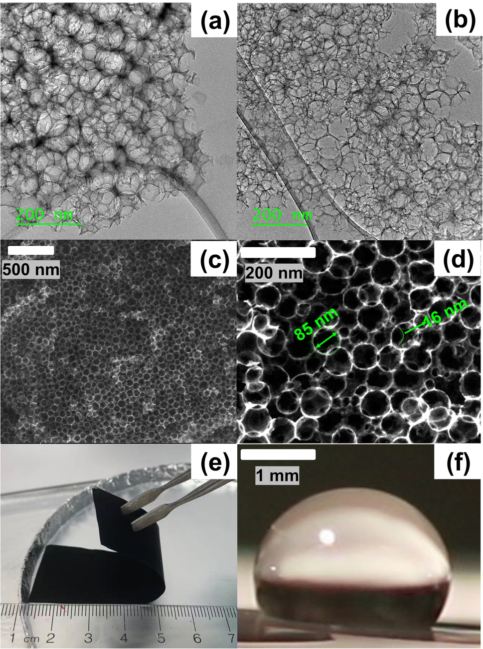 | ||
| Fig. 1 (a) and (b) TEM images of as-prepared NCS-85, showing well-defined, 3-D interconnected 85 nm pore diameters. (c) and (d) SEM images at various magnifications of pore geometry in 1500 °C heated NCS-85 membrane, with (e) showing an optical image of the membrane and (f) showing the contact angle of 1 M KCl on the NCS-85 membrane surface. | ||
When the NCS-85 membrane was first placed in contact with the 1 M KCl solution surface without the application of potential (i.e., the open-circuit potential), a concave meniscus is seen to form immediately (e.g., yellow line in Fig. 2(c) and (f) and S3†), confirming its hydrophobic character. Note that a wait time of 600 s (which was not shown in Fig. 2 and S4, and in Videos S1–S11,†) with time zero considered to be the time at which the potential was first applied was implemented prior to the application of each potential to ensure that there was no spontaneous imbibition. When the potential of the NCS-85 was altered anywhere within a potential window of ca. +0.7 VAg/AgCl and −0.9 VAg/AgCl (all potentials are given vs. the Ag/AgCl reference electrode unless otherwise indicated) and held for various times, no significant changes were observed, with the meniscus remaining concave and no imbibition seen to occur (Videos S5 and S6†). However, as the potential was extended above +0.7 VAg/AgCl or more negative than −0.9 VAg/AgCl, electrocapillary imbibition began to occur, as shown in Fig. 3, Videos S1–S4 and S7–S11.† Importantly, at these threshold potentials, imbibition begins abruptly with a change in the meniscus from concave to convex during roughly the first ca. 1 to 4 s, followed by electrocapillary imbibition.
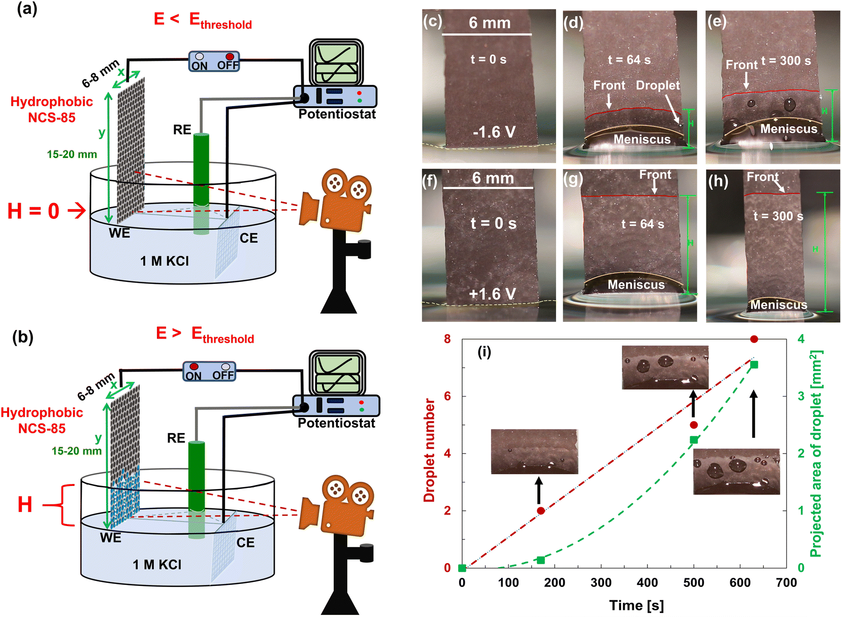 | ||
| Fig. 2 (a and b) Illustration of the experimental setup used for the electrocapillary imbibition experiments in 1 M KCl solution, showing the difference in the wetting of the hydrophobic NCS-85 working electrode (WE) with applied (a) E < Ethreshold and (b) E > Ethreshold, where Ag/AgCl in 3 M NaCl served as the reference electrode (RE) and a Pt mesh as the counter electrode (CE). (c–e) Electro-dewetting phenomena at −1.6 VAg/AgCl and (f–h) at +1.6 VAg/AgCl, where t is the time passed during the observed imbibition behavior. Electro-dewetting (droplet expulsion) is seen at negative potentials in (d) and (e), and is also shown in Videos S1–S4.† The red lines in the images show the approximate imbibition front, while the yellow lines show the approximate contour of the meniscus. (i) Droplet number and projected area given as a function of time at −2 VAg/AgCl. | ||
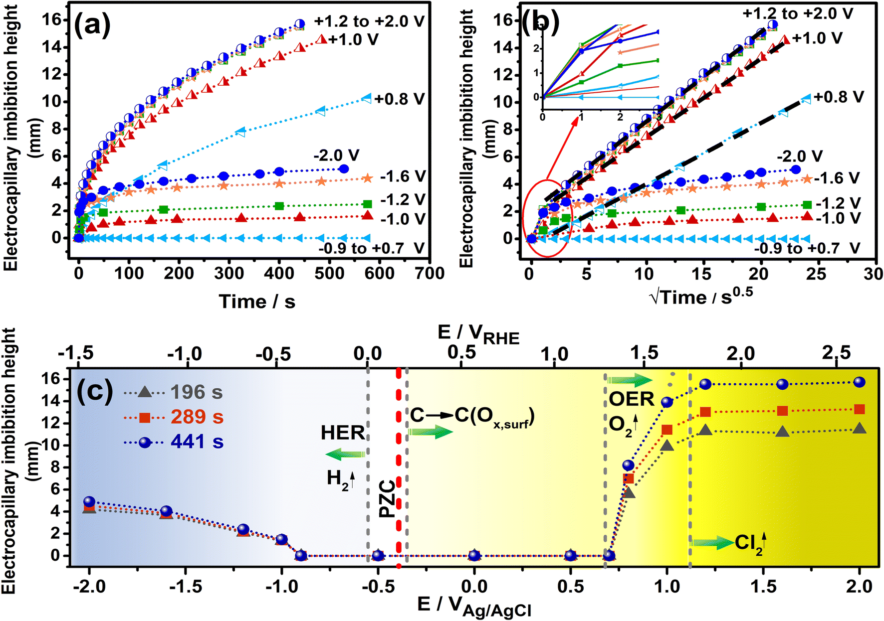 | ||
| Fig. 3 (a) Measured H values as a function of time and (b) the square root of time for imbibition observed at hydrophobic NCS-85 at various applied potentials vs. Ag/AgCl in 1 M KCl. Dashed, black and bold lines have been added through the linear segments of the data collected at positive potentials. Inset of (b): expanded view of behavior during initial meniscus jump within the first few seconds. (c) H as a function of potential (vs. Ag/AgCl (lower axis) and vs. RHE (upper axis)) at various times after the application of different potentials. A reasonable estimate of the pzc (potential of zero charge, red vertical dashed line) of the NCS-85 and the thermodynamically possible Faradaic reactions that can occur in this medium are also shown (vertical dashed grey lines). The blue color depicts the increasing rates of hydrogen evolution that can occur at negative potentials, while the yellow color shows that carbon can oxidize at >−0.35 VAg/AgCl, oxygen can evolve at >+0.68 VAg/AgCl, and chlorine can evolve at >+1.1 VAg/AgCl. Note that the lines joining the individual data points have been added as a guide to the eye. | ||
Fig. 2 shows that electrocapillary imbibition height (H) is significantly larger when electro-imbibition occurred at positive (vs. EAg/AgCl) vs. at negative (vs. EAg/AgCl) potentials. Another very interesting observation is that the imbibition front (red line) is generally more contoured and slightly fingered at negative vs. positive potentials and that liquid droplets have been expelled from the wetted area of the NCS-85 surface at sufficiently negative potentials, e.g., −2 VAg/AgCl (Video S1†), −1.6 VAg/AgCl (Fig. 2(d) and (e) and Video S2†), −1.2 VAg/AgCl (Video S3†) and −1 VAg/AgCl (Video S4†). Droplet formation and coalescence is seen to have increased as the potential was made more negative, while no liquid droplets were ever observed in the wetted area when imbibition occurred at positive potentials (Fig. 2(g) and (h) and Videos S7–S11†), even after long periods of polarization. Fig. 3(a) shows a plot of the imbibition height (H) in the NCS-85 as a function of time at the various potentials investigated here, with the data, obtained from camera images such as in Fig. 2, shown plotted vs. time in Fig. 3(a)t1/2 in Fig. 3(b). This plot shows that imbibition after the meniscus jump is linear with t1/2, which is typical for imbibition processes, according to the Lucas–Washburn equation ( where k is the permeability, μ is the liquid viscosity, θa is the advancing liquid contact angle, γ is the interfacial tension of liquid–gas, and Re is the effective radius).26 It is also seen that the plots in Fig. 3(b) for +0.8 VAg/AgCl and +1.0 VAg/AgCl have a lower slope than the constant slope seen at potentials of ≥+1.2 VAg/AgCl and that imbibition at positive potentials is significantly faster than at negative potentials, giving very high rates of ca. 80 nl s−1 mm−2 at short times under positive polarization, with this calculation assuming that the NCS-85 is fully saturated. At negative potentials, these rates are lower, i.e., 34 nl s−1 mm−2, consistent with the smaller H values seen in Fig. 2 over the same time periods. In comparison, a somewhat faster rate of over 80 nl s−1 mm−2 has been reported for a CNT sponge at −1 VAg/AgCl in 1 M KOH.2
A plot of the H values measured from the camera images at various times of imbibition vs. the applied potential is shown in Fig. 3(c), where the potential of the NCS-85 is also given vs. a second reference electrode, namely the reversible hydrogen elelctrode (RHE), on the upper axis. Furthermore, the thermodynamic equilibrium potentials of all Faradaic reactions that could potentially occur within the potential range studied in this pH = 5.5 1 M KCl medium are shown as dashed grey vertical lines. The graded blue color reflects the increasing tendency for hydrogen evolution to occur as the potential is extended negatively of ca. −0.55 VAg/AgCl, while the graded yellow color indicates the increasing driving force for carbon oxidation by its reaction with water as the potential exceeds ca. −0.3 VAg/AgCl. The darker yellow color shows that oxygen evolution can occur at increasing rates above +0.68 VAg/AgCl and chlorine evolution at above +1.1 VAg/AgCl. Notably, the potentials given for the Faradaic reactions in Fig. 3(c) are thermodynamic values and do not account for positive (for oxidation reactions) or negative (for reduction reactions) overpotentials that would be induced by sluggish kinetics of the reactions. The pzc has been reported to be in the range of −0.36 to −0.395 VAg/AgCl for relatively hydrophobic single graphene nanoplatelets and graphite, respectively.28–31 Considering that it is difficult to determine the pzc of highly porous carbons, especially of their internal surfaces, we surveyed the literature and chose a value of −0.38 VAg/AgCl here, similar to what has been reported for other carbons that are expected to be similar to our NCS material and where the values were also obtained in neutral solutions.
As a whole, Fig. 3 confirms that electrocapillary imbibition does not occur over the potential range of −0.9 ≤ E ≤ +0.7 VAg/AgCli.e., H remains at 0 mm, at least after 600 s of holding at these potentials, with the onset of electrocapillary imbibition occurring roughly between −1 and +0.8 VAg/AgCl. As has been stated in the literature,21 the observed abrupt transition from a non-wetting to wetting state, reported also at positive potentials for CNT membranes, is not what is predicted by the Young–Lippmann equation. Furthermore, the pzc (marked in Fig. 3(c)) is clearly not positioned symmetrically between the onset of imbibition, suggestive of additional factors besides just EDL charging and related contact angle changes being responsible for the observed imbibition behavior. Also, the rates of imbibition (Fig. 3(a) and (b)) are clearly very different at positive vs. negative polarization, arguing for different imbibition mechanisms as a function of polarity. The plot of H vs. EAg/AgCl in Fig. 3(c) reinforces these differences, with H exhibiting a value that is independent of the potential once above 1.2 VAg/AgCl showing that the imbibition rate is now entirely dependent on time, with the linear H vs. t1/2 plots (Fig. 3(b)) now overlapping fully. In comparison, in the range of −1 VAg/AgCl to −2 VAg/AgCl, as a more negative voltage is applied, slower electrocapillary imbibition is observed. Also, water droplet expulsion from the wetted NCS-85 area at negative potentials (Fig. 2(d), (e) and (i)) is never seen under positive polarization imbibition conditions. We therefore set out to better understand these differences by determining the driver of imbibition into our ordered, self-supported, hydrophobic NCS-85 membrane materials at both positive and negative potentials.
When considering the Lippmann theory, a perturbation of the potential of a conducting material in a solution, in either a positive or negative direction vs. Epzc (assumed to be −0.38 VAg/AgCl), will cause immediate EDL charging with a roughly symmetrical dependence on the sign of the applied voltage and thus the solid–liquid surface energy.32,33 However, this is not observed here (Fig. 3) at the two polarities in 1 M KCl, indicating that other critical factors are at play. The primary drivers of the onset of imbibition at positive vs. negative potentials, seemingly related to different processes, are discussed below in turn.
Fig. 3(c) and Video S6† clearly show that, as the potential of the dry, hydrophobic NCS-85 membrane is initially made positive of the pzc, no changes in the imbibition behavior are seen and the meniscus remains concave (Fig. S3†) until a potential in the range of +0.75–0.8 VAg/AgCl is reached, when imbibition begins abruptly and rapidly. Fig. 3(c) also shows that at above −0.35 VAg/AgCl (0.21 VRHE), carbon is thermodynamically vulnerable to oxidation by reaction with water, expected to form CO2 but also typically producing a range of surface oxygen-containing functionalities.34 Therefore, under positive polarization, carbon oxidation and related CO2 formation could precede the observed imbibition at positive potentials. Moreover, it is evident from Fig. 3(c) that O2 can be produced from water at ≥+0.68 VAg/AgCl (≥+1.23 VRHE).34 However, no gas bubbles were seen visually in the meniscus area until imbibition was well underway, namely at ≥+1.2 VAg/AgCl, consistent with carbon being a poor OER catalyst. Chlorine evolution from chloride oxidation is not expected to be relevant here, as its oxidation potential is quite high, at ≥+1.1 VAg/AgCl (≥+1.65 VRHE), a potential at which imbibition is well underway (Fig. 3). Note that several oxidation reactions can occur simultaneously at carbon electrodes in 1 M KCl at > 0.2 VRHE, including carbon oxidation, as well as oxygen and chlorine evolution. As the kinetics of these reactions are unknown and hence the onset potentials cannot be predicted, the thermodynamic potentials are provided in order to indicate which reactions could potentially start at which potentials.
To determine if these electrochemical reactions are related to the sudden onset of imbibition at positive potentials, the current/time transients measured during holding at each potential ≥ +0.8 VAg/AgCl were examined in detail (Fig. 4(a)). This figure shows that the currents all decay initially, reflective of EDL charging. However, the fact that steady-state currents are seen at longer times, with no effect of solution convection on their magnitude, makes it clear that Faradaic reactions occur throughout the range of positive potentials at which imbibition is seen. If only EDL charging were occurring, the current densities would have plummeted to zero at constant H values,1 which is clearly not the case here. A closer examination of the charges passed during the full transient at each potential allowed a comparison to be made with the charges expected for just EDL charging of the wetted area of the NCS-85, assuming full access of solution into the pores and using the 200 m2 g−1 area27 of the NCS-85, as shown in Table S2.† This analysis involves several assumptions, including the value of the pzc (−0.38 VAg/AgCl), as well as the value of the double layer capacitance (DLC) of the hydrophobic NCS-85 material in 1 M KCl, using a reasonable value of 15 μF cm−2.35 In the classic papers of Yeager36,37 and then Gerischer,38 the latter paper treating, a DLC of 2–4 μF cm−2 was obtained, although it was acknowledged that the DLC could be higher by 2–3 times, depending on the pH, electrolyte type and concentration. More recently, the DLC for activated carbon was found to be between 5 and 20 μF cm−2 when using the measured Brunauer, Emmett and Teller (BET) surface area. Also, the DLC for activated carbon fibers39 has been reported to be 14.5 μF cm−2 for micropores, similar to that of the basal plane of carbon (15–20 μF cm−2), but 7.5 μF cm−2 for the external surface. Carbons with higher DLCs include activated porous carbons (10–25 μF cm−2 (ref. 40)), MXene-derived carbons (24 μF cm−2 (ref. 41)), nitrogen-enriched carbon materials (73 μF cm−2 (ref. 42)) and functionalized graphene sheets (54 μF cm−2 (ref. 43). More importantly, in recent work with the NCS,27 we showed that use of a DLC value of 15 μF cm−2 resulted in excellent agreement between the electrochemically active surface area and the surface area obtained using BET methods. Therefore, we have used this DLC value of 15 μF cm−2 throughout the present work.
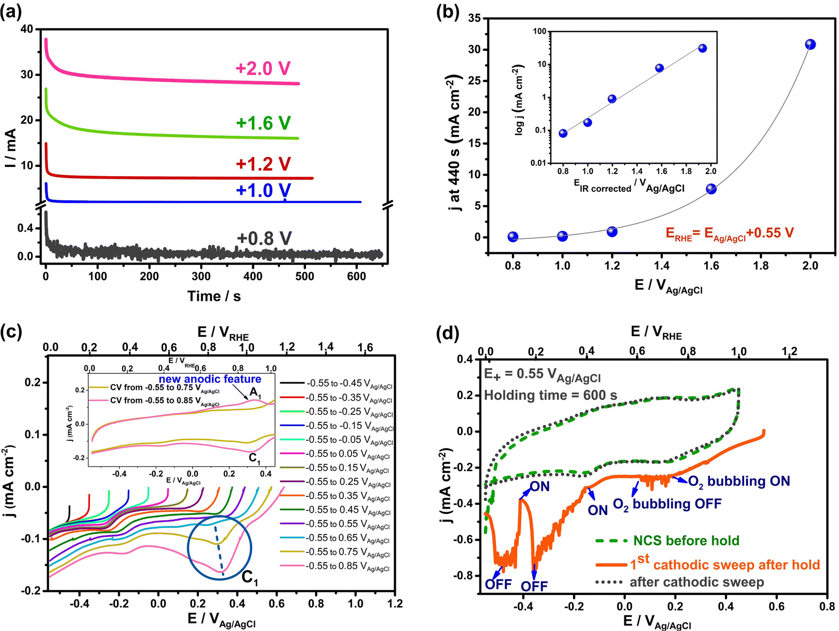 | ||
| Fig. 4 Currents passed during electrocapillary imbibition experiments at positive polarization (a and b) and during cyclic voltammetry (5 mV s−1) (c and d) of an initially dry, hydrophobic NCS-85 membrane in 1 M KCl. (a) Current vs. time at various applied positive potentials for the data in the Fig. 3(a). (b) Current density versus potential at 440 s in Cartesian scale for data in (a). Inset of (b): logarithm of current density vs. IR-corrected potentials at 440 s. (c and d) Data for submerged NCS-85: (c) superimposed cathodic sweeps (5 mV s−1) recorded after extension of the potential in 100 mV increments from −0.55 to +0.85 VAg/AgCl in 1 M KCl with carbon paper used as the counter electrode. The NCS-85 potential on the X axis is given vs. both Ag/AgCl (bottom) and RHE (top). The blue-circled reduction peak (C1), centered at 0.25–0.35 VAg/AgCl (dashed blue line), is seen only when the potential is extended above +0.75 VAg/AgCl, which correlates with the potential at which imbibition began in Fig. 2 and 3. Inset in (c): superimposed CVs (−0.55 to +0.75 and −0.55 to +0.85 VAg/AgCl), showing the appearance of a new anodic peak A1, correlating with peak C1 in the negative scan. (d) Cathodic linear scan (solid orange line) at 10 mV s−1, showing that introduction of oxygen into solution results in no oxygen reduction currents until a potential of < ca. −0.15 VAg/AgCl is applied, indicating that peak C1 in (c) is not due to oxygen reduction. | ||
Based on these calculations, it is seen that the experimental charges are all larger than the charge calculated for EDL charging, which is further evidence that Faradaic reactions are occurring when the potential is ≥+0.8 VAg/AgCl. This was confirmed by plotting the measured current at the end of the transient, corrected for the estimated wetted area vs. EAg/AgCl+, as shown in Fig. 4(b). The plot is exponential, at least at potentials of +1.2 VAg/AgCl or greater, indicative of Faradaic reactions that are activation controlled and thus obey the Butler–Volmer equation,44 as expected for oxygen evolution reaction (OER), CO2 and Cl2 evolution, but not EDL charging. Because the currents in these electro-imbibition experiments are passing through the protruding imbibed NCS-85 membrane to a height of H, an IR drop is expected due to ion transport limitations within the NCS-85 pores that extend from the meniscus to a height of H.
After estimating the resistance value, a plot of the logarithm of current vs. the IR-corrected potential (Tafel plot) is shown in the inset of Fig. 4(b), exhibiting a linear relationship with a Tafel slope value of ∼240 mV per decade of current. This relationship is a strong indicator of the occurrence of an electrochemical reaction that is rate controlled by reaction kinetics, not by diffusion or migration processes. Examples of the type of reaction that should exhibit this relationship include gas evolution, gas reduction, organic oxidation, metal dissolution, metal deposition etc. Thus, Fig. 4(b) supports the occurrence of a reaction such as oxygen evolution under our conditions. It is also noteworthy that the most commonly measured Tafel slope for Faradaic reactions such as oxygen evolution and hydrogen evolution at room temperature is 120 mV per decade of current. However, a doubled Tafel slope (2 × 120 mV) has frequently been reported for reactions such as gas evolution and reduction processes when they occur at porous electrodes with long and narrow pores, properties that are fully consistent with the NCS-85 internal structure.45–48 These results imply that Faradaic electrochemistry would be more pronounced in the meniscus region and less so near the imbibition front, especially when higher currents are passed (large H and positive potentials).48
To help identify the oxidation process that occurs when imbibition begins at ca. +0.8 VAg/AgCl, a completely dry, hydrophobic NCS-85 membrane was fully immersed in 1 M KCl (Fig. S1†) and cyclic voltammograms were collected at gradually increasing potential limits. Fig. 4(c) shows only the negative scans, recorded for the immersed NCS-85 when the potential was increased in 100 mV increments, all at 5 mV s−1. At <+0.8 VAg/AgCl (+1.35 VRHE), only EDL charging/discharging occurs, while at potentials positive of this, a small but clear new reduction peak is seen, centered at +0.3 to +0.35 VAg/AgCl. It is important to note that the first hints of this new peak are seen only when the potential reaches ∼+0.8 VAg/AgCl, which is the same potential at which the abrupt onset of imbibition was seen in Fig. 3.
The inset in Fig. 4(c) shows that, once the potential has exceeded +0.8 VAg/AgCl, a similarly sized matching anodic peak is seen in the oxidation scan following the cathodic sweeps in the main part of the figure. This pair of peaks, which grow in size as the potential is made more positive, is characteristic of the presence of oxidized surface functionalities on the NCS-85 surface that can be reduced and re-oxidized, as is typical for carbon surfaces when groups such as quinol/quinone moieties are present.49 Our hypothesis is therefore that the onset of NCS-85 surface oxidation in the region of contact of the NCS with the solution then causes a local increase in wettability, thus acting as the switch that turns on electro-imbibition. In previous work with superhydrophobic aligned multiwalled CNT membranes, carbon oxidation was also invoked as the catalyst for imbibition of a water droplet at positive polarization.21 Interestingly, a very small rising oxidation current is seen near the positive end of each scan, even before the onset of the OER can occur. These currents can be attributed to the formation of very small amounts of surface oxygen functionalities due to carbon oxidation or to irreversible oxidation to form trace amounts of CO2, which can occur at any potential positive of ∼+0.2 VRHE. Even so, we have defined the onset of imbibition as when the macroscopically observed jump in H occurs and also when we see clear evidence for the presence of peak C1 in Fig. 4(c).
As stated above, the OER can begin at >+0.68 VAg/AgCl, but a significant overpotential is expected to be present unless carbon is doped with heteroatoms.50,51 To rule out that the OER is initiating imbibition under positive polarization, Fig. S5† shows the CVs collected as the potential is made more positive, demonstrating the onset of what is likely the OER at ca. +1.05 VAg/AgCl (+1.6 VRHE), a potential at which electro-imbibition is already well underway (Fig. 3). Also, to rule out that the small cathodic peak shown in Fig. 4(c) at +0.3 to +0.35 VAg/AgCl is due to the reduction of electrochemically generated oxygen, oxygen was bubbled into the solution during the CV scans, showing (Fig. 4(d)) that the oxygen reduction reaction (ORR) can only occur at the NCS-85 at potentials < +0.5 VRHE in 1 M KCl. Thus, the reduction of oxygen is not responsible for the observed (circled) redox peaks in Fig. 4(c).
To summarize, carbon surface oxidation, forming functionalities such as –C–OH, –C![[double bond, length as m-dash]](https://www.rsc.org/images/entities/char_e001.gif) O, and –COOH, is clearly playing an important role in the onset of electro-imbibition inside the NCS-85 at positive potentials under our experimental conditions. The surface groups that form initially in the menisucus region then lower the local contact angle and induce imbibition, with these oxidized surface groups then forming throughout the wetted area of the NCS-85 as the front moves upward. It is also predicted from Fig. 4(c) and our knowledge of carbon oxidation10 that holding at higher potentials should increase the surface density of oxide groups, both in the wetted region and at the imbibition front, thus lowering the contact angle. This is indeed seen to be the case after polarization at +1.6 and +2 VAg/AgCl in Fig. S6,† with the observed contact angle gradient consistent with the IR drop discussion above. For example, after 480 s polarization at +1.6 and +2 VAg/AgCl, the contact angle in the meniscus area is ca. 80° and 60°, respectively, as compared to its original value of >100° (Fig. 1(d) and Table S1†). It is clear that it is the region of the imbibed NCS-85 membrane that is closest to the solution that shows the most pronounced difference in contact angle with potential (and thus in the density of oxygen surface functionalities), while the differences are more muted further into the imbibed region (middle, top). This is very likely due to a larger IR drop at larger imbibition heights at +2 VAg/AgClvs. at +1.6 VAg/AgCl, as evidenced by the i/t plots in Fig. 4(a).
O, and –COOH, is clearly playing an important role in the onset of electro-imbibition inside the NCS-85 at positive potentials under our experimental conditions. The surface groups that form initially in the menisucus region then lower the local contact angle and induce imbibition, with these oxidized surface groups then forming throughout the wetted area of the NCS-85 as the front moves upward. It is also predicted from Fig. 4(c) and our knowledge of carbon oxidation10 that holding at higher potentials should increase the surface density of oxide groups, both in the wetted region and at the imbibition front, thus lowering the contact angle. This is indeed seen to be the case after polarization at +1.6 and +2 VAg/AgCl in Fig. S6,† with the observed contact angle gradient consistent with the IR drop discussion above. For example, after 480 s polarization at +1.6 and +2 VAg/AgCl, the contact angle in the meniscus area is ca. 80° and 60°, respectively, as compared to its original value of >100° (Fig. 1(d) and Table S1†). It is clear that it is the region of the imbibed NCS-85 membrane that is closest to the solution that shows the most pronounced difference in contact angle with potential (and thus in the density of oxygen surface functionalities), while the differences are more muted further into the imbibed region (middle, top). This is very likely due to a larger IR drop at larger imbibition heights at +2 VAg/AgClvs. at +1.6 VAg/AgCl, as evidenced by the i/t plots in Fig. 4(a).
This is also consistent with the observed increase in the X-ray photoelectron spectroscopy determined oxygen content of the wetted NCS-85 membrane after polarization at +2 VAg/AgCl. The oxygen content before polarization was as low as 0.3 at% (Fig. S7 and S8†), which then increased to the highest degree of oxidation observed (7 at%) in the wetted region after 480 s at +2 VAg/AgCl polarization (Fig. S8†), which is in good agreement with the contact angle measurements in Fig. S6(b).† The oxygen that is detected is confirmed to be due to the presence of various electrochemically formed functional groups, such as O–CO, C–OH, CO, COO– and C–O–C, at the NCS surface, as evidenced from the deconvoluted C 1s and O 1s XPS results shown in Fig. S9.†
Overall, these results suggest that NCS-85 surface oxidation in 1 M KCl solution, driven by the application of a critical potential (∼+0.8 VAg/AgCl), is correlated with the sharp onset of imbibition, with oxidation believed to occur throughout the wetted area as H increases with time. This is consistent with the fact that NCS-85 membranes exposed to electro-imbibition conditions at positive potentials cannot be reused, as their surfaces are permanently altered. Even so, it should be noted that we cannot fully rule out a contribution from pressure driven flow resulting from CO2 or O2 evolution to the rapid rise of H under positive polarization once imbibition has been initiated.
Electro-imbibition into hydrophobic porous carbon electrodes at negative bias has been previously studied by several groups, based primarily on monitoring mass gain. It was shown that the Lucas–Washburn equation was obeyed, once an onset potential for electro-imbibition of −0.52 VAg/AgCl was surpassed,2 also showing controlled on/off behavior.2–4,52 The beneficial effects of the presence of ordered pores within the carbon matrix were also demonstrated in terms of the rate of observed imbibition.3 However, these studies were all carried out in 1 M KOH in recognition of the fact that a potential of roughly −1 VAg/AgCl can be applied without risk of any interference from Faradaic reactions, specifically the hydrogen evolution reaction (HER).
The present work was carried out in neutral KCl solutions, but this does come with a risk of a less negative thermodynamic potential for the HER, as will be discussed below in terms of some possible causes for the observed onset of imbibition into the NCS-85 membrane at negative potentials as well as its unique characteristics. Fig. 3(c) shows that imbibition into hydrophobic NCS-85 begins at around −1 VAg/AgCl, which is ca. −0.6 V negative of the pzc. At this potential, the rate of the HER, which can begin at <−0.55 VAg/AgCl (<0 VRHE), is already very high, as seen by active bubble generation in the concave meniscus under these conditions (Videos S1–S5†). Notably, oxygen reduction, which is expected to be negligible under these conditions, does not generate bubbles. Also different from the observations at positive potentials, at potentials more negative than the threshold for imbibition, expulsion of liquid droplets from the hydrophobic NCS was observed, as shown in Fig. 2 and more fully in Videos S1–S4.† As exudation occurs, the imbibition front motion slows down.
While electrowetting theory would be a convenient explanation for these results, the situation is very likely much more complex here, given the nanoporous nature of the NCS-85 film and that wetting at negative potentials is not observed until well negative of the onset of vigorous hydrogen evolution and the meniscus jump. This is very different from the situation at positive potentials, where the onset of Faradaic NCS-85 surface oxidation correlates with the onset of imbibition and possibly trace oxygen evolution. It is also clear that, once Faradaic reactions begin, the assumption of thermodynamic equilibrium in classical models of electrowetting of conductors is broken.33 Also important is the fact that carbon oxidation cannot occur at these negative potentials and thus the explanations given above for imbibition at positive potentials do not apply here. In fact, the phenomenology is more complex and more applicable to many cases in practice where liquids exhibit unwanted imbibition into hydrophobic carbons.53–55 Indeed, the NCS-85 is hydrophobic at the start of these experiments and remains so even after long times at negative potentials, allowing re-use of the same piece of NCS after the electro-imbibition experiments.
To further amplify the differences in the imbibition behavior seen at positive vs. negative potentials, Fig. 5(a) shows that the current initially exhibits a very short, sharp spike, likely as EDL charging occurs in the meniscus region, then increasing with time and stabilizing with time at negative polarization. However, the observed steady-state currents are only very weakly dependent on potential (Fig. 5(b)), especially when corrected for the wetted (imbibed) surface area, with the current density only doubling from −1 to −2 VAg/AgCl instead of changing by orders of magnitude, as was the case at positive potentials (Fig. 4(b)). This could indicate that the double layer is not developing properly inside the NCS-85 at negative potentials or that the HER that occurs within the wetted NCS-85 area is transport controlled, perhaps due to slow removal of H2 gas trapped behind solution in the pores. It is also possible that the pH inside the imbibed region is becoming increasingly more alkaline during the HER, thus moving the HER equilibrium potential negatively with time. Whatever the reason, these characteristics are very different than seen under positive polarization, thus meriting very different explanations that are tied more to physical phenomena.
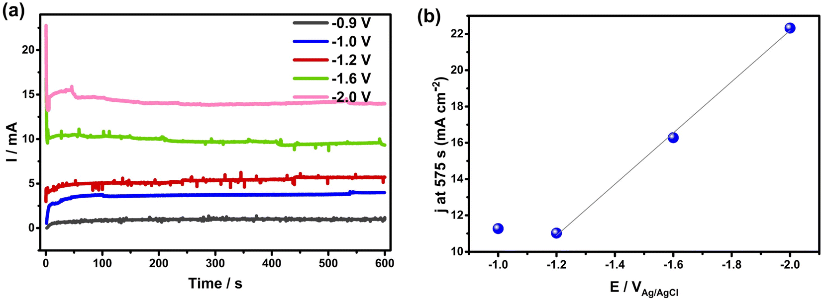 | ||
| Fig. 5 Electrochemistry during electrocapillary imbibition experiments of hydrophobic NCS-85 at negative potentials, all in 1 M KCl. (a) Current vs. time at various applied potentials. (d) Current density at 575 s in Cartesian scale vs. applied potential, showing a weak but rather linear dependence at <−1.2 VAg/AgCl. | ||
We therefore propose that, at negative potentials, the imbibition process operates in two stages, namely nucleation and steady-state imbibition. The nucleation event is most likely an EDL charging driven meniscus jump, while the steady-state phase likely involves various physical processes, such as Marangoni flow,56,57 adsorption induced deformation,58 and pressure driven flow from the HER, as the HER is the dominant electrochemical reaction at negative potentials. Fig. 5(a) further supports this by showing an increasing current during the first ca. 100 s, after which it remains largely constant over time.
It is known that he interface between hydrophobic materials and an electrolyte can display physically unstable electrochemical behavior. Scholz59 further points out that local variation in contact angle can give rise to Marangoni streaming.56,57 Combined with the fluid convection induced by the HER, this creates a complex and dynamic NCS-85/solution interaction at the initial concave meniscus between the NCS-85 and the electrolyte. Recognizing the non-equilibrium implications, qualitatively, an additional driver is the decrease in the contact angle with increasingly negative potential (charge) vs. the pzc, as described by the Young–Lippmann equation.32
There is also the influence of what is known as electrolyte-induced deformation.60 When the hydrophobic NCS-85 membranes are fully immersed in water, extreme distortion of the film occurs (Fig. S10†), sometimes leading to macroscopic cracking. Bangham and Fakhoury58 first showed that adsorption of water by charcoal gave rise to volumetric expansion, while others61 have indicated that the strains created can be sufficient to fracture the particles. Lakhanpal62 showed how adsorption of various species can initially cause expansion of the graphite structure and then contraction, as the vapor pressure of the adsorbate increases. Others in the field60 have confirmed this observation,62 putting forward an explanation. Thus, given these various phenomena, we anticipate some intrusion of fluid into the initially dry pores in contact with the fluid reservoir meniscus, as driven by gas pressure, Marangoni convection, and turbulence.
The physical turbulence caused by the HER in the meniscus regions and the disturbance from the macroscopic meniscus jump might force a finger of electrolyte to enter a pore. Once this finger enters a pore, its behavior has been modeled63 for both hydrophilic and hydrophobic pore filling phenomena. In the hydrophilic case (positive potentials), the model shows that the fluid wets the surface of the pore and then fills the volume and, once full, the fluid moves to the next connected pore. However, for the hydrophobic case at negative potentials, there is no driving force for the fluid to wet the pore surface. Nevertheless, with sufficient pressure on the fluid, developed by sufficiently high rates of gas evolution, the fluid will enter the pore as a “finger”. When this finger contacts a pore wall, further expansion occurs, in all cases trapping a gas volume between the pore wall and the fluid and creating voids.63 The presence of trapped gases at negative potentials agrees with the observed exudation of droplets (Fig. 2(d) and (e)), while the finger formation is consistent with the more contoured imbibition front seen at negative polarization, relative to the case at positive potentials (Fig. 2(g)–(k)).
Extending this concept63 to our work, we expect further Faradaic reactions to occur inside the partially filled pore with time at negative potentials, in our case being the HER. The continuous formation of gas will then gradually increase the pressure in this trapped gas volume and force the fluid to move into the adjacent connected pore (see cartoon in Fig. S11†). The pressure necessary to advance the fluid into the next dry pore would be less than necessary to displace the fluid downward and back into the reservoir. Thus, advancement of the imbibition front is anticipated, consistent with our observations (Fig. 2 and S4†).
This explanation also applies to the observed expulsion of fluid from the NCS surface, as shown in Fig. 2 and Videos S1–S4† and is consistent with the observation that the imbibition front motion slows down once the droplets form. The pressure driven process then either moves fluid upwards within the NCS-85, causing H to increase, or it drives fluid out of the NCS-85 to the surface, following the easiest pathway, e.g., through defects or slightly larger pores and pore necks, leading to a nearby outer surface and exudation as droplets. Notably, the NCS-85 remains hydrophobic at all stages of electro-imbibition at negative potentials, thus allowing start/stop imbibition to be observed (Fig. S12†), similar to what was reported previously for hydrophobic CNTs.2
We also show that the electrocapillary imbibition of the hydrophobic NCS-85 membranes in 1 M KCl can be controllably switched from an “on” state to an “off” state by modifying the applied potential, as shown in Fig. S12 and Video S12.† This is demonstrated during multiple cyclic voltammetry scans between +2 VAg/AgCl and −2 VAg/AgCl, showing behavior that is qualitatively consistent with electrocapillary imbibition in nanoporous media.1–3 It is seen that the liquid front moved upwards at positive potentials but was never observed to flow back into the reservoir, rather remaining constant due to the very small gravitational force associated with the small amount of imbibed liquid inside the NCS-85 and also as a result of strong contact line pinning at the nanoscale.23,24 This is in contrast to the reversible electrocapillary imbibition observed in micro-channels.5
Conclusions
The present work demonstrates the use of a novel self-supported and hydrophobic nanoporous carbon scaffold (NCS) to establish the fundamental origin of the observed polarity-dependent electrocapillary imbibition behavior, a topic that is not well understood in the literature. We show here that directional transport of liquids can be directed into and throughout the monodisperse and 3D-interconnected pores, in this case having a nominal pore diameter 85 nm. The electro-imbibition behavior was investigated by bringing the NCS-85 membrane just into contact with the surface of the solution (1 M KCl) and then closely monitoring the imbibition process by tracking the front to a height of H during the application of either positive or negative potentials (up to −2 or +2 VAg/AgCl), using a camera.A key observation was that no imbibition took place over quite a broad range of potentials (between −0.9 and +0.7 VAg/AgCl) and that the electro-imbibition is asymmetric with respect to the potential of zero charge (pzc) (ca. −0.38 VAg/AgCl). Imbibition was found to commence abruptly at a positive potential of ≥+0.8 VAg/AgCl (ca. +1.2 Vpzc), shown to correlate with the onset of several Faradaic reactions, including carbon oxidation to form oxygen-containing groups and CO2, as well as water oxidation to form O2. The double layer within the imbibed carbon structure was demonstrated to behave as expected with applied voltage, based on the observed exponential dependence of the current density on potential, thus ruling out any double layer saturation effects. It was proposed that the oxygen functionalities formed on the NCS-85 surface at the NCS/solution interface make the NCS-85 surface more wettable, thus initiating imbibition. Notably, after imbibition at sufficiently positive potentials, the NCS-85 membrane becomes hydrophilic, indicative of the development of an oxidized surface, as verified by post-mortem X-ray photoelectron spectroscopy surface analyses.
Under negative polarization, high rates of the hydrogen evolution reaction (HER) are seen well before imbibition began at −1 VAg/AgCl, with imbibition proposed to be nucleated by the application of a critical double layer potential that serves to drive a meniscus jump. Imbibition at negative potentials is hypothesized to be governed by physical processes, such as Marangoni flow, adsorption induced deformation, and pressure driven flow from the HER, all of critical importance in fluid flow through a confined, monodisperse nanopore network. Unlike what is seen at positive polarization, the imbibed solution is displaced out from the NCS-85 nanopores at negative polarization, forming liquid droplets on the NCS-85 surface and slowing down the further increase in H. Notably, the NCS-85 membrane remained hydrophobic after polarization at negative potentials and could even be resused.
Our studies on electrocapillary imbibition of these nanoporous carbon sheets under positive and negative polarization could have several important implications for electrochemical systems. As one example, one of the challenges encountered in alkaline Zn/air battery cathodes is the undesired full penetration of solution throughout its porous structure,53,64,65 which consists of hydrophobic carbon particles held together by a Teflon binder. This results in an unwanted loss of the electrochemically active interface (the triple phase boundary), resulting in a significant loss in performance with time. Similarly, during the operation of proton-exchange membrane (PEM) fuel cell cathodes, flooding is experienced in microporous carbon layers. The present work shows that flooding can occur if the potential becomes sufficiently positive to promote carbon surface oxidation, making the carbon become hydrophilic. Therefore, a recommendation would be to avoid these higher potentials and/or chemically modify the carbon surface with hydrophobic functional groups to minimize the available carbon surface area available for electrochemical oxidation.66 Analogously, flooding induced by electrocapillary imbibition can also occur at negative potentials, which could be a problem in CO2 electrolyzers, especially when commonly used hydrophobic surfaces are employed and gaseous products are generated, e.g., CO.67,68 As our studies show that trapped gases in hydrophobic nanopores can cause imbibition, nanoscale optimization of the pore morphology, aiming at accommodating pressure build-up and minimizing tortuosity between neighboring particles, should help to alleviate these types of detrimental effects.
Methods
Materials
All of the electrocapillary imbibition experiments were performed using a hydrophobic, self-supported nanoporous carbon scaffold membrane (nominal 85 nm pore diameter, NCS-85) with the procedure used for NCS membrane fabrication described in detail in our previous work.23–25 The as-fabricated NCS-85 is hydrophilic, but was converted to a hydrophobic form by heating at 1500 °C for 2 h in a nitrogen (N2) atmosphere (ALPHAGAZ, 99.999%), resulting in the removal of the majority of the surface oxygen functional groups.69Toray carbon paper, used in the submerged NCS-85 electrochemistry experiments, was obtained from the Fuel Cell store, while the epoxy used to seal parts of the electrodes in these experiments was obtained from JB Weld. KCl with 99.9% purity was obtained from Sigma-Aldrich. Deionized water with a conductivity of 1.63 μS cm−1 was used to prepare the 1 M KCl solution in this work.
Methods
A SP-150 Bio-Logic potentiostat was used to control the applied potential, all in a 1 M KCl solution. A three-electrode system was used in all experiments, with no efforts made to control the gas atmosphere and no solution agitation employed. The working electrode (WE) consisted of the hydrophobic NCS-85 membrane, the counter electrode (CE) was a high surface area Pt gauze, connected to a Pt wire that was embedded in a sealed glass tube, and the reference electrode (RE) was an Ag/AgCl electrode containing 3 M NaCl solution. The pH inside the meniscus region as well as in droplets that were exuded from the wetted area of the NCS-85 at negative potentials was measured using pH paper (Micro Essential Lab), where the average pH of the KCl solution was ca. 5.5. For better understanding, the potential of the NCS-85 is also given vs. the reversible hydrogen electrode (RHE), where ERHE = EAg/AgCl + 0.209 + 0.0591pH, assuming a pH of 5.5.A piece of NCS-85 (properties given in Table S1†) was first placed above an empty Petri dish. Next, 1 M KCl solution was gradually added to the Petri dish until it just contacted the base of the NCS material. Due to the hydrophobicity of the NCS-85 used here, a concave meniscus developed immediately and no spontaneous imbibition occurred. Subsequently, a constant positive or negative potential vs. Ag/AgCl was applied, holding for times up to 10–15 minutes. Once a potential was reached at which imbibition occurred, the color contrast between the wetted and the dry NCS-85 areas could be clearly seen, allowing for the monitoring of the real-time electrocapillary imbibition front height (H) using a Canon EOS Rebel SL2 camera (25 frames per second and with a resolution of 15–25 μm per pixel). H was then quantified using open-source software (ImageJ). All measurements were conducted at ambient conditions (i.e., 1 atm and 23 ± 2 °C). To guarantee replicability, a new NCS-85 sample was used for each measurement and each measurement was repeated at least three times. To avoid evaporation effects, the entire setup was placed in a sealed and transparent glass container.26
A schematic of the experimental setup used for the immersed NCS-85 electrochemistry experiments is shown in Fig. S1.† Briefly, Toray carbon paper was used as a strengthening support to prevent curling of the hydrophobic NCS-85 when submerged in 1 M KCl solution, with interference from the electrochemical response of the Toray paper avoided by coating it with epoxy. Electrical connection was made to the NCS-85 membranes using silver paint, then covering the silver with epoxy, followed by rinsing with ethanol and then with 1 M KCl solution (5 times). The electrode was then submerged in the KCl solution and used as the working electrode (geometric area = 1 cm2), employing an Ag/AgCl reference electrode and a piece 5 × 1 cm2 of Toray paper as the counter electrode.
Physical characterization
The NCS-85 morphology was determined using a FEI Quanta FEG 250 Environmental Field-Emission Scanning Electron Microscope (E-FESEM) at the University of Calgary with the accelerating voltage kept at 30 kV. Double-sided carbon tape (VWR) was used to attach the NCS-85 membranes to the SEM stub. Bright-field transmission electron micrographs (TEM) of NCS-85 were acquired using a JEOL JEM-ARM200cFS/TEM located at the NanoFAB Facility at the University of Alberta, equipped with a cold Field-Emission Gun (cFEG) and a probe Cs corrector (operating acceleration voltage 200 kV). TEM samples were prepared by dispersing a powdered form of the NCS in ethanol and then mounting a drop of this liquid onto a carbon-coated Cu TEM grid. The wettability of the 1500 °C heat-treated NCS-85 membrane was determined both before and after the electrocapillary imbibition experiments using the sessile water droplet method,70 including at various points within what had been the wetted areas after various times of imbibition.X-Ray photoelectron spectroscopy (XPS) was used to determine the degree of carbon oxidation before and after the imbibition experiments, with the analysis carried out at the NanoFAB Centre at the University of Alberta using a Kratos Axis Ultra spectrometer with monochromatized Al Kα (hν = 1486.71 eV). The spectrometer was calibrated to the binding energy of Au 4f7/2 (84.0 eV) with reference to the Fermi level. The analysis chamber pressure during the analyses was at or better than 5 × 10⁻¹⁰ torr. A hemispherical electron-energy analyzer working at a pass energy of 20 eV was used to collect core-level spectra, while the survey spectrum within a range of binding energies from 0 to 1100 eV was collected at an analyzer pass energy of 160 eV. Charge effects were corrected for by using the C 1s peak at 284.8 eV. A Shirley background was applied to subtract the inelastic background of core-level peaks. Non-linear optimization using the Marquardt Algorithm (Casa XPS) was used to determine the peak model parameters such as peak positions, widths and peak intensities. The model peak to describe XPS core-level lines for curve fitting was a product of Gaussian and Lorentzian functions. The oxygen content was calculated from the survey spectra using the major elemental peaks and sensitivity factors provided by the database. CASA XPS was used for component analysis to fit the C 1s spectra to peaks related to different chemical bonds.
Data availability
Data will be available on request.Author contributions
B. P. performed the electrocapillary imbibition experiments, discovered the voltage-dependent physical phenomena, and wrote the initial draft of the paper. M. O. V. performed the fully immersed electrochemistry experiments and contributed significantly to the writing of the paper. X. T. fabricated the nanoporous carbon scaffold (NCS) materials, while B. P., M. O. V., X. T. and C. D. characterized the NCS materials. B. P., M. O. V., R. R. Jr, C. R. C., and V. I. B. all contributed to the interpretation of the results. C. R. C. and V. I. B. funded this research. V. I. B. supervised the research project and wrote the majority of the final version of the manuscript, which all of the authors have approved.Conflicts of interest
There are no conflicts to declare.Acknowledgements
V. I. B. acknowledges the Natural Sciences and Engineering Research Council of Canada (NSERC) for financial support, as well as support from the Canada Research Chairs program. C. R. C. thanks the sponsors of the Tight Oil Consortium (TOC) and Ovintiv and Shell for support of his Chair position in Unconventional Gas and Light Oil Research at the University of Calgary, Department of Geoscience. B. P. acknowledges funding support from the Chinese Scholarship Council, TOC and NSERC EOR CRD, while M. O. V. acknowledges support from the Canada First Research Excellence Fund (CFREF). Both M. O. V. and X. T. also thank NSERC for the overall support of this work. We also thank Dr Marwa Atwa for assistance with the TEM imaging of the NCS-85 material.References
- Y. Xue, J. Markmann, H. Duan, J. Weissmüller and P. Huber, Switchable Imbibition in Nanoporous Gold, Nat. Commun., 2014, 5, 4237 CrossRef CAS PubMed.
- Y. Xue, Y. Yang, H. Sun, X. Li, S. Wu, A. Cao and H. Duan, A Switchable and Compressible Carbon Nanotube Sponge Electrocapillary Imbiber, Adv. Mater., 2015, 27(44), 7241–7246 CrossRef CAS PubMed.
- B. Yao, J. Chen, Y. Li, Y. Wen, M. Wu and G. Shi, Oriented Graphene Foam with Tunable Wettability by Electrocapillary for Switchable and Ultra-Fast Imbibition, Adv. Mater. Interfaces, 2016, 3(24), 1600774 CrossRef.
- C. Hua, Y. Shang, X. Li, X. Hu, Y. Wang, X. Wang, Y. Zhang, X. Li, H. Duan and A. Cao, Helical Graphene Oxide Fibers as a Stretchable Sensor and an Electrocapillary Sucker, Nanoscale, 2016, 20(8), 10659 RSC.
- M. W. J. Prins, W. J. J. Welters and J. W. Weekamp, Fluid Control in Multichannel Structures by Electrocapillary Pressure, Science, 2001, 291(5502), 277–280 CrossRef CAS PubMed.
- J. L. Trick, C. Song, E. J. Wallace and M. S. P. Sansom, Voltage Gating of a Biomimetic Nanopore: Electrowetting of a Hydrophobic Barrier, ACS Nano, 2017, 11(2), 1840–1847 CrossRef CAS PubMed.
- B. E. Logan and M. Elimelech, Membrane-Based Processes for Sustainable Power Generation Using Water, Nature, 2012, 488, 313–319 CrossRef CAS PubMed.
- S. Porada, R. Zhao, A. van der Wal, V. Presser and P. M. Biesheuvel, Review on the Science and Technology of Water Desalination by Capacitive Deionization, Prog. Mater. Sci., 2013, 58(8), 1388–1442 CrossRef CAS.
- B. Pan, X. Yin, Y. Ju and S. Iglauer, Underground Hydrogen Storage: Influencing Parameters and Future Outlook, Adv. Colloid Interface Sci., 2021, 294, 102473 CrossRef CAS PubMed.
- N. Heinemann, J. Alcalde, J. M. Miocic, S. J. T. Hangx, J. Kallmeyer, C. Ostertag-Henning, A. Hassanpouryouzband, E. M. Thaysen, G. J. Strobel, C. Schmidt-Hattenberger, K. Edlmann, M. Wilkinson, M. Bentham, R. Stuart Haszeldine, R. Carbonell and A. Rudloff, Enabling Large-Scale Hydrogen Storage in Porous Media – the Scientific Challenges, Energy Environ. Sci., 2021, 14(2), 853–864 RSC.
- M. Rahman, M. A. Stott, M. Harrington, Y. Li, M. J. N. Sampad, L. Lancaster, T. D. Yuzvinsky, H. F. Noller, A. R. Hawkins and H. Schmidt, On Demand Delivery and Analysis of Single Molecules on a Programmable Nanopore-Optofluidic Device, Nat. Commun., 2019, 10(1), 3712 CrossRef CAS PubMed.
- J. A. Trainham and J. Newman, A Comparison between Flow-through and Flow-by Porous Electrodes for Redox Energy Storage, Electrochim. Acta, 1981, 26(4), 455–469 CrossRef CAS.
- R. Omrani and B. Shabani, Gas Diffusion Layer Modifications and Treatments for Improving the Performance of Proton Exchange Membrane Fuel Cells and Electrolysers: A Review, Int. J. Hydrogen Energy, 2017, 42(47), 28515–28536 CrossRef CAS.
- E. W. Lees, B. A. W. Mowbray, F. G. L. Parlane and C. P. Berlinguette, Gas Diffusion Electrodes and Membranes for CO2 Reduction Electrolysers, Nat. Rev. Mater., 2022, 7, 55–64 CrossRef CAS.
- B. S. Gallardo, V. K. Gupta, F. D. Eagerton, L. I. Jong, V. S. Craig, R. R. Shah and N. L. Abbott, Electrochemical Principles for Active Control of Liquids on Submillimeter Scales, Science, 1999, 283(5398), 57–60 CrossRef CAS PubMed.
- J. Baschuk and X. Li, Modelling of Polymer Electrolyte Membrane Fuel Cells with Variable Degrees of Water Flooding, J. Power Sources, 2000, 86(1–2), 181–196 CrossRef CAS.
- T. Zhou, N. Zhang, C. Wu and Y. Xie, Surface/Interface Nanoengineering for Rechargeable Zn-Air Batteries, Energy Environ. Sci., 2020, 13, 1132–1153 RSC.
- I. Morcos, Electrocapillary Phenomena at the Stress-Annealed Pyrolytic Graphite Electrode, J. Phys. Chem., 1972, 76(19), 2750–2753 CrossRef CAS.
- Y. Wei and C. Q. Jia, Intrinsic Wettability of Graphitic Carbon, Carbon, 2015, 87, 10–17 CrossRef CAS.
- P. Iamprasertkun, A. Ejigu and R. A. W. Dryfe, Understanding the Electrochemistry of “Water-in-Salt” Electrolytes: Basal Plane Highly Ordered Pyrolytic Graphite as a Model System, Chem. Sci., 2020, 11(27), 6978–6989 RSC.
- Z. Wang, L. Ci, L. Chen, S. Nayak, P. M. Ajayan and N. Koratkar, Polarity-Dependent Electrochemically Controlled Transport of Water through Carbon Nanotube Membranes, Nano Lett., 2007, 7(3), 697–702 CrossRef CAS PubMed.
- J. Pu, S. Wan, Z. Lu, G. Zhang, L. Wang, X. Zhang and Q. Xue, Controlled Water Adhesion and Electrowetting of Conducting Hydrophobic Graphene/Carbon Nanotubes Composite on Engineering Materials, J. Mater. Chem. A, 2013, 11254 Search PubMed.
- V. Birss, X. Li, D. Banham and D. Y. Kwok, Porous Carbon Films, US Pat., US20170014780A1, 2019 Search PubMed.
- M. N. Islam, U. N. Shrivastava, M. Atwa, X. Li, V. I. Birss and K. Karan, Highly-Ordered Nanoporous Carbon Scaffold with Controllable Wettability as the Microporous Layer for Fuel Cells, ACS Appl. Mater. Interfaces, 2020, 12(35), 39215–39226 CrossRef CAS PubMed.
- B. Pan, C. R. Clarkson, M. Atwa, C. Debuhr, A. Ghanizadeh and V. I. Birss, Wetting Dynamics of Nanoliter Water Droplets in Nanoporous Media, J. Colloid Interface Sci., 2021, 589, 411–423 CrossRef CAS PubMed.
- B. Pan, C. R. Clarkson, M. Atwa, T. Xia, C. Debuhr, A. Ghanizadeh and V. Birss, Spontaneous Imbibition Dynamics of Liquids in Partially-Wet Nanoporous Media: Experiment and Theory, Transp. Porous Media, 2021, 137, 555–574 CrossRef CAS.
- M. Atwa, X. Li, Z. Wang, S. Dull, S. Xu, X. Tong, R. Tang, H. Nishihara, F. Prinz and V. Birss, Scalable Nanoporous Carbon Films Allow Line-of-Sight 3D Atomic Layer Deposition of Pt: Towards a New Generation Catalyst Layer for PEM Fuel Cells, Mater. Horiz., 2021, 8(9), 2451–2462 RSC.
- L. Eliad, G. Salitra, A. Soffer and D. Aurbach, Ion Sieving Effects in the Electrical Double Layer of Porous Carbon Electrodes: Estimating Effective Ion Size in Electrolytic Solutions, J. Phys. Chem. B, 2001, 105(29), 6880–6887 CrossRef CAS.
- J. Poon, C. Batchelor-Mcauley, K. Tschulik and R. G. Compton, Single Graphene Nanoplatelets: Capacitance, Potential of Zero Charge and Diffusion Coefficient, Chem. Sci., 2015, 6, 2869–2876 RSC.
- D. Golub, A. Soffer and Y. Oren, The Electrical Double Layer of Carbon and Graphite Electrodes, J. Electroanal. Chem. Interfacial Electrochem., 1989, 260(2), 383–392 CrossRef CAS.
- M. Li, M. N. Idros, Y. Wu, T. Burdyny, S. Garg, X. S. Zhao, G. Wang and T. E. Rufford, The Role of Electrode Wettability in Electrochemical Reduction of Carbon Dioxide, J. Mater. Chem. A, 2021, 9(35), 19369–19409 RSC.
- F. Mugele and J. C. Baret, Electrowetting: From Basics to Applications, J. Phys.: Condens. Matter, 2005, 17, 28 Search PubMed.
- F. Mugele and J. Heikenfeld, Electrowetting: Fundamental Principles and Practical Applications, Wiley, 2019 Search PubMed.
- Y. Yi, G. Weinberg, M. Prenzel, M. Greiner, S. Heumann, S. Becker and R. Schlögl, Electrochemical Corrosion of a Glassy Carbon Electrode, Catal. Today, 2017, 295, 32–40 CrossRef CAS.
- D. Banham, F. Feng, J. Burt, E. Alsrayheen and V. Birss, Bimodal, Templated Mesoporous Carbons for Capacitor Applications, Carbon, 2010, 48(4), 1056–1063 CrossRef CAS.
- J.-P. Randin and E. Yeager, Differential Capacitance Study of Stress-Annealed Pyrolytic Graphite Electrodes, J. Electrochem. Soc., 1971, 118(5), 711 CrossRef CAS.
- J. P. Randin and E. Yeager, Differential Capacitance Study on the Basal Plane of Stress-Annealed Pyrolytic Graphite, J. Electroanal. Chem. Interfacial Electrochem., 1972, 36(2), 257–276 CrossRef CAS.
- H. Gerischer, J. P. Randin, E. Yeager, J. A. Molla and S. Gupta, Electrons and Phonons in Layered Crystal Structures, Carbon, 1985, 89(123), 415 Search PubMed.
- H. Shi, Activated Carbons and Double Layer Capacitance, Electrochim. Acta, 1996, 41(10), 1633–1639 CrossRef CAS.
- P. Simon and Y. Gogotsi, Capacitive Energy Storage in Nanostructured Carbon-Electrolyte Systems, Acc. Chem. Res., 2013, 46(5), 1094–1103 CrossRef CAS PubMed.
- J. Wang, J. Tang, B. Ding, V. Malgras, Z. Chang, X. Hao, Y. Wang, H. Dou, X. Zhang and Y. Yamauchi, Hierarchical Porous Carbons with Layer-by-Layer Motif Architectures from Confined Soft-Template Self-Assembly in Layered Materials, Nat. Commun., 2017, 8(1), 1–9 CrossRef PubMed.
- L. F. Chen, Y. Lu, L. Yu and X. W. Lou, Designed Formation of Hollow Particle-Based Nitrogen-Doped Carbon Nanofibers for High-Performance Supercapacitors, Energy Environ. Sci., 2017, 10(8), 1777–1783 RSC.
- T. Lin, I. W. Chen, F. Liu, C. Yang, H. Bi, F. Xu and F. Huang, Nitrogen-Doped Mesoporous Carbon of Extraordinary Capacitance for Electrochemical Energy Storage, Science, 2015, 350(6267), 1508–1513 CrossRef CAS PubMed.
- J. Bockris and A. K. N. Reddy, Modern Electrochemistry, Springer, 1970 Search PubMed.
- B. V. Tilak, R. S. Yeo and S. Srinivasan, Electrochemical Energy Conversion—Principles, Springer, 1981, pp. 39–122 Search PubMed.
- Modern Electrochemistry, ed. J. O. Bockris, B. E. Conway, E. Yeager and R. E. White, Springer US, Boston, MA, 1981 Search PubMed.
- J. N. Soderberg, A. C. Co, A. H. C. Sirk and V. I. Birss, Impact of Porous Electrode Properties on the Electrochemical Transfer Coefficient, J. Phys. Chem. B, 2006, 110(21), 10401–10410 CrossRef CAS PubMed.
- D. W. Banham, J. N. Soderberg and V. I. Birss, Pt/Carbon Catalyst Layer Microstructural Effects on Measured and Predicted Tafel Slopes for the Oxygen Reduction Reaction, J. Phys. Chem. C, 2009, 113(23), 10103–10111 CrossRef CAS.
- K. H. Kangasniemi, D. A. Condit and T. D. Jarvi, Characterization of Vulcan Electrochemically Oxidized under Simulated PEM Fuel Cell Conditions, J. Electrochem. Soc., 2004, 151(4), E125 CrossRef CAS.
- G.-L. Tian, M.-Q. Zhao, D. Yu, X.-Y. Kong, J.-Q. Huang, Q. Zhang and F. Wei, Nitrogen-Doped Graphene/Carbon Nanotube Hybrids: In Situ Formation on Bifunctional Catalysts and Their Superior Electrocatalytic Activity for Oxygen Evolution/Reduction Reaction, Small, 2014, 10(11), 2251–2259 CrossRef CAS PubMed.
- S. Chen, J. Duan, M. Jaroniec and S.-Z. Qiao, Nitrogen and Oxygen Dual-Doped Carbon Hydrogel Film as a Substrate-Free Electrode for Highly Efficient Oxygen Evolution Reaction, Adv. Mater., 2014, 26(18), 2925–2930 CrossRef CAS PubMed.
- X. Li, Y. Xue, M. Zou, D. Zhang, A. Cao and H. Duan, Direct Oil Recovery from Saturated Carbon Nanotube Sponges, ACS Appl. Mater. Interfaces, 2016, 8(19), 12337–12343 CrossRef CAS PubMed.
- P. Pei, K. Wang and Z. Ma, Technologies for Extending Zinc-Air Battery's Cycle life: A Review, Appl. Energy, 2014, 128, 315–324 CrossRef CAS.
- M. P. Clark, M. Xiong, K. Cadien and D. G. Ivey, High Performance Oxygen Reduction/Evolution Electrodes for Zinc-Air Batteries Prepared by Atomic Layer Deposition of MnOx, ACS Appl. Energy Mater., 2020, 3(1), 603–613 CrossRef CAS.
- P. Satjaritanun and I. V. Zenyuk, Water Management Strategies for PGM-Free Catalyst Layers for Polymer Electrolyte Fuel Cells, Curr. Opin. Electrochem., 2021, 100622 CrossRef CAS.
- X. Yang, D. Baczyzmalski, C. Cierpka, G. Mutschke and K. Eckert, Marangoni Convection at Electrogenerated Hydrogen Bubbles, Phys. Chem. Chem. Phys., 2018, 20(17), 11542–11548 RSC.
- A. Viviani and A. Zuev, Deformation and Rupture of a Horizontal Liquid Layer by Thermal and Solutal Marangoni Flows, Energy Convers. Manag., 2008, 49(11), 3232–3236 CrossRef.
- D. H. Bangham and N. Fakhoury, The Expansion of Charcoal Accompanying Sorption of Gases and Vapours, Nature, 1928, 681–682 CrossRef CAS.
- F. Scholz, R. Gulaboski, U. Schröder and A. Doménech-Carbó, Electrochemistry of Immobilized Particles and Droplets: Experiments with Three-Phase Electrodes, Springer, 2015 Search PubMed.
- Y. Zeng, L. Liu, H. Zhang, D. D. Do and D. Nicholson, A Monte Carlo Study of Adsorption-Induced Deformation in Wedge-Shaped Graphitic Micropores, Chem. Eng. J., 2018, 346, 672–681 CrossRef CAS.
- A. A. Fomkin, A. V. Shkolin, A. L. Pulin, I. E. Men'shchikov and E. V. Khozina, Adsorption-Induced Deformation of Adsorbents, Colloid J., 2018, 80(5), 578–586 CrossRef CAS.
- M. L. Lakhanpal and E. A. Flood, Stresses And Strains in Adsorbate–Adsorbent Systems: IV. Contradictions of Activated Carbon On Adsorption of Gases and Vapors at low Initial Pressures, Can. J. Chem., 1957, 35(8), 887–899 CrossRef CAS.
- M. M. Sedeh and J. M. Khodadadi, Interface Behavior and Void Formation during Infiltration of Liquids into Porous Structures, Int. J. Multiphase Flow, 2013, 57, 49–65 CrossRef.
- B. Pichler, B. S. Berner, N. Rauch, C. Zelger, H.-J. Pauling, B. Gollas and V. Hacker, The Impact of Operating Conditions on Component and Electrode Development for Zinc-Air Flow Batteries, J. Appl. Electrochem., 2018, 48(9), 1043–1056 CrossRef CAS.
- D. Schröder, T. Arlt, U. Krewer and I. Manke, Analyzing Transport Paths in the Air Electrode of a Zinc Air Battery Using X-Ray Tomography, Electrochem. Commun., 2014, 40, 88–91 CrossRef.
- F. Forouzandeh, X. Li, D. W. Banham, F. Feng, A. J. Kakanat, S. Ye and V. Birss, Improving the Corrosion Resistance of Proton Exchange Membrane Fuel Cell Carbon Supports by Pentafluorophenyl Surface Functionalization, J. Power Sources, 2018, 378, 732–741 CrossRef CAS.
- M. E. Leonard, L. E. Clarke, A. Forner-Cuenca, S. M. Brown and F. R. Brushett, Investigating Electrode Flooding in a Flowing Electrolyte, Gas-Fed Carbon Dioxide Electrolyzer, ChemSusChem, 2020, 13(2), 400–411 CrossRef CAS PubMed.
- B. De Mot, J. Hereijgers, M. Duarte and T. Breugelmans, Influence of Flow and Pressure Distribution inside a Gas Diffusion Electrode on the Performance of a Flow-by CO2 Electrolyzer, Chem. Eng. J., 2019, 378, 122224 CrossRef CAS.
- L. Qingfeng, H. A. Hjuler and N. J. Bjerrum, Oxygen Reduction on Carbon Supported Platinum Catalysts in High Temperature Polymer Electrolytes, Electrochim. Acta, 2000, 45(25–26), 4219–4226 CrossRef.
- B. Pan, X. Yin and S. Iglauer, A Review on Clay Wettability: From Experimental Investigations to Molecular Dynamics Simulations, Adv. Colloid Interface Sci., 2020, 102266 CrossRef CAS PubMed.
Footnote |
| † Electronic supplementary information (ESI) available. See DOI: https://doi.org/10.1039/d2sc05705k |
| This journal is © The Royal Society of Chemistry 2023 |