
 Open Access Article
 This Open Access Article is licensed under a Creative Commons Attribution-Non Commercial 3.0 Unported Licence
Selective and high-rate CO2 electroreduction by metal-doped covalent triazine frameworks: a computational and experimental hybrid approach†
Shintaro
Kato
 a,
Takuya
Hashimoto
a,
Kazuyuki
Iwase
b,
Takashi
Harada
a,
Shuji
Nakanishi
*ac and
Kazuhide
Kamiya
*ac
a,
Takuya
Hashimoto
a,
Kazuyuki
Iwase
b,
Takashi
Harada
a,
Shuji
Nakanishi
*ac and
Kazuhide
Kamiya
*ac
aResearch Center for Solar Energy Chemistry, Graduate School of Engineering Science, Osaka University, 1-3 Machikaneyama, Toyonaka, Osaka 560-8531, Japan. E-mail: nakanishi.shuji.es@osaka-u.ac.jp; kamiya.kazuhide.es@osaka-u.ac.jp
bInstitute of Multidisciplinary Research for Advanced Materials, Tohoku University, 2-1-1 Katahira, Aoba-ku, Sendai, Miyagi 980-8577, Japan
cInnovative Catalysis Science Division, Institute for Open and Transdisciplinary Research Initiatives, Osaka University, Suita, Osaka 565-0871, Japan
First published on 13th December 2022
Abstract
The electrochemical CO2 reduction reaction (CO2RR) has attracted intensive attention as a technology to achieve a carbon-neutral society. The use of gas diffusion electrodes (GDEs) enables the realization of high-rate CO2RRs, which is one of the critical requirements for social implementation. Although both a high reaction rate and good selectivity are simultaneously required for electrocatalysts on GDEs, no systematic study of the relationship among active metal centers in electrocatalysts, reaction rate, and selectivity under high-rate CO2RR conditions has been reported. In the present study, we employed various metal-doped covalent triazine frameworks (M-CTFs) as platforms for CO2 reduction reaction (CO2RR) electrocatalysts on GDEs and systematically investigated them to deduce sophisticated design principles using a combined computational and experimental approach. The Ni-CTF showed both high selectivity (faradaic efficiency (FE) > 98% at −0.5 to −0.9 V vs. reversible hydrogen electrode) and a high reaction rate (current density < −200 mA cm−2) for CO production. By contrast, the Sn-CTF exhibited selective formic acid production, and the FE and partial current density reached 85% and 150 mA cm−2, respectively. These results for the CO2RR activity and selectivity at high current density with respect to metal centers correspond well with predictions based on first-principles calculations. This work is the first demonstration of a clear relationship between the computational adsorption energy of intermediates depending on metal species and the experimental high-rate gaseous CO2RR.
Introduction
The excessive emission of CO2 due to the use of fossil fuels is becoming a serious problem that threatens the sustainable development of society. The development of technologies that use CO2 as an alternative carbon feedstock and convert it to other valuable chemicals is therefore important.1,2 Various methodologies for effective CO2 reduction have been widely investigated, including biological,3 thermochemical,4 photochemical,5 and electrochemical approaches.1,2,6 Among them, electrochemical CO2 reduction has attracted intensive attention because it can be driven directly using electricity generated from renewable energy sources, such as solar and wind.7,8 For the industrial implementation of CO2 electrolysis, the development of reaction systems that can rapidly and selectively reduce CO2 to value-added products is critical.Although dissolved CO2 is conventionally used as the substrate, the current densities are limited to ∼20 mA cm−2 because of the low solubility and slow diffusion of CO2.9,10 The use of gas diffusion electrodes (GDEs) is one approach to overcome this problem originating from the low solubility and slow diffusion in the substrate.11–27 Gaseous substrates can be directly supplied to the triple-phase boundary at the GDE, where the catalyst material, electrolyte, and gas pores intersect.10,28 For example, de Arquer et al. achieved a current density of 1.3 A cm−2 for ethylene formation at 45% energy efficiency using a GDE loaded with Cu nanoparticles,29 and de Jesus and his coworkers achieved 600 mA cm−2 for CO formation at a faradaic efficiency (FE) of 80% using a gas-fed zero-gap electrolyzer loaded with Ag nanocubes.30 Based on the above reports, metal species in electrocatalysts are the most critical factor determining CO2RR activity. However, compared with the use of typical dissolved CO2 as a substrate (i.e., low-current-density electrolysis), the electrocatalytic activity for high-current-density CO2 electrolysis depending on metal species has not been well studied. Metal and metal oxide nanoparticles have different sizes and surface atomic arrangements depending on the metal species, even when synthesized using similar procedures.31–35 Since immersion-type electrodes, including single-crystal or polycrystalline metal plates, are not available for GDEs, unlike in the case of conventional low-current-density electrolysis, the different morphologies of nanoparticles become the critical bottleneck for the systematic study of the dependence of gaseous CO2 reduction activity on metal species.36,37
Recently, single-atom electrocatalysts (SAECs), which consist of singly isolated metal sites dispersed on heterogeneous supports, have drawn attention as a robust analog of homogeneous catalysts.38,39 When well-designed materials are employed as supports for SAECs, the coordination environments of the metal centers are unambiguously defined, similar to the case for homogeneous organometallic catalysts.40,41 Therefore, SAECs have great potential as alternatives to heterogeneous electrocatalysts composed of bulk metals. We have focused on metal-doped covalent triazine frameworks (M-CTFs) as a platform for SAECs on GDEs. CTFs are a class of conjugated microporous polymers with a 1,3,5-triazine moiety as the linker.42,43 CTFs can immobilize a wide variety of 3d, 4d, and 5d metal centers due to abundant nitrogen atoms in their pores, and they exhibit various electrocatalytic functions corresponding to these metal centers, such as oxygen reduction and hydrogen oxidation reactions.44–55 In particular, we have systematically examined the electrocatalytic CO2RR activity of CTFs doped with 3d metals (Co, Ni, or Cu) in neutral solutions using a conventional substrate of dissolved CO2 at a total current density of 2 mA cm−2.48 We observed that the adsorption strength of CO2RR intermediates for CO production varies depending on the metal center and that the CO generation activity corresponds to the adsorption strength. In addition, our group has recently demonstrated that gaseous ethylbenzene can be effectively oxidized to acetophenone in aqueous electrolytes using a GDE carrying a single-Ru-atom-doped CTF.11 Given this background, we speculated that metal-doped CTFs (M-CTFs) would be an ideal platform for the electrocatalysts of gaseous substrates on GDEs. Furthermore, considering the availability of various metal atoms with a controlled structure, metal-doped CTFs are also suitable for theoretical studies to predict catalytic activity and gain atomic-level insights into the reaction mechanism.
Based on these considerations, CTFs doped with various metals are used as CO2RR electrocatalysts on GDEs, and we systematically investigate the relationship between metal species and high-rate CO2RR activity using a combined computational and experimental approach.
Results and discussion
Our previous theoretical studies demonstrated that M-CTFs can widely tune the adsorption strength of intermediates for the dinitrogen56 and oxygen reduction reactions57 during electrochemical reactions when the metal species is varied. Similar to our approach in these previous studies, in the present work, we attempted to predict the CO2RR activity and selectivity of M-CTFs by calculating the adsorption energy of CO2RR intermediates using density functional theory (DFT).Let us consider the theoretical CO2RR on M-CTFs by calculating the Gibbs free energy of formation (ΔG) for each reaction intermediate COOH* and CO*. Fig. 1(a) and (b) show the relaxed structure and the difference in charge density on Ni-CTF before and after CO adsorption, respectively. An electron density accumulates at the p orbital of the adsorbed CO*; whereas a depletion in electron density is observed at the Ni site. These results indicate that p-back donation from the Ni site to CO* occurred.58,59 This electron transfer leads to effective activation of key intermediates.59Fig. 1(c) shows ΔG(CO) plotted against ΔG(COOH) for different M-CTFs. The linear relationship between ΔG(COOH) and ΔG(CO) indicates that the so-called scaling relationship applies to CO2RR on SAECs.60–66 That is, ΔG(COOH) and ΔG(CO) cannot be independently modulated.61–66 On the basis of this relationship, a volcano-type relation accompanied by a single peak between ΔG(COOH) or ΔG(CO) and CO2RR activity would appear despite the existence of more than one intermediate.67,68 Both the ΔG(COOH) and the ΔG(CO) values indicate stronger adsorption on metal centers with fewer d-electrons.68–71 When CO or COOH is adsorbed onto a metal center, bonding and antibonding orbitals are formed.68,69 The degree of filling of the antibonding orbitals increases with increasing number of d-electrons, resulting in weaker adsorption of CO or COOH.68–71Fig. 1(d) shows the free energy diagram for CO production at 0 V and −0.98 V vs. computational hydrogen electrode (CHE) on different M-CTFs (M = Co, Cu, Ni, Ru, Sn). At −0.98 V vs. CHE, the Sn- and Cu-CTFs exhibit an endergonic reaction for COOH* formation, whereas a potential barrier exists at the CO desorption step for the Ru- and Co-CTFs (Fig. 1(d) and Table S1†). By contrast, all of the elementary steps on the Ni-CTF are exergonic. The dependence of the free energy diagrams on the metal centers can be explained as follows. The CO and COOH adsorption strength simultaneously increases with decreasing number of d-electrons (Fig. 1(c)). The ΔG value for COOH* formation decreases with increasing adsorption strength of COOH*, whereas the barrier of CO desorption steps increases with increasing CO adsorption energy. Therefore, the Cu- and Sn-CTFs exhibited lower adsorption strengths than an optimal catalyst, resulting in a barrier for COOH* formation. By contrast, the CO desorption step becomes the potential-determining step for the Ru- and Co-CTFs, whose adsorption strengths are greater than the optimal value. We also calculated the H-adsorption energies to evaluate the selectivity of CO2RR vs. hydrogen evolution reaction (HER) (Fig. 2). There is a linear relationship between ΔG(H) and ΔG(COOH) in a similar manner to bulk metals and other SAECs.72–74 When this linear relationship is applicable, stronger and weaker adsorption of H* or COOH* leads to the selectivity for HER and CO2RR, respectively, based on previous reports.75,76 These results made us predict that Fe- and Ru-CTFs might be active for the HER rather than CO2RR.
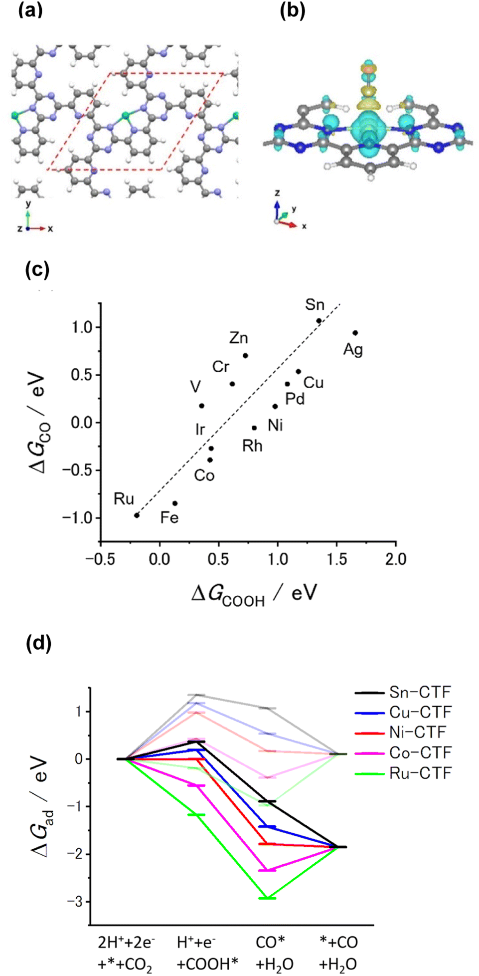 | ||
| Fig. 1 (a) Optimized structure of Ni-CTF for DFT calculation (gray: C, white: H, blue: N, green: Ni). The red dashed line shows the unit cell. Approximately the same structure was obtained for all of the investigated M-CTFs. (b) Charge-density difference for Ni-CTF before and after COOH adsorption. The isosurface level is 0.003 e bohr−3. The yellow and cyan areas represent regions of electron accumulation and depletion, respectively (gray: C, white: H, blue: N, green: Ni). (c) ΔGCO expressed in terms of ΔGCOOH for each M-CTF. (d) Free energy diagrams for CO generation on Sn (black), Cu (blue), Ni (red), Co (purple), and Ru (green)-doped CTFs at 0 V (pale lines) and −0.98 V vs. CHE (dark lines). | ||
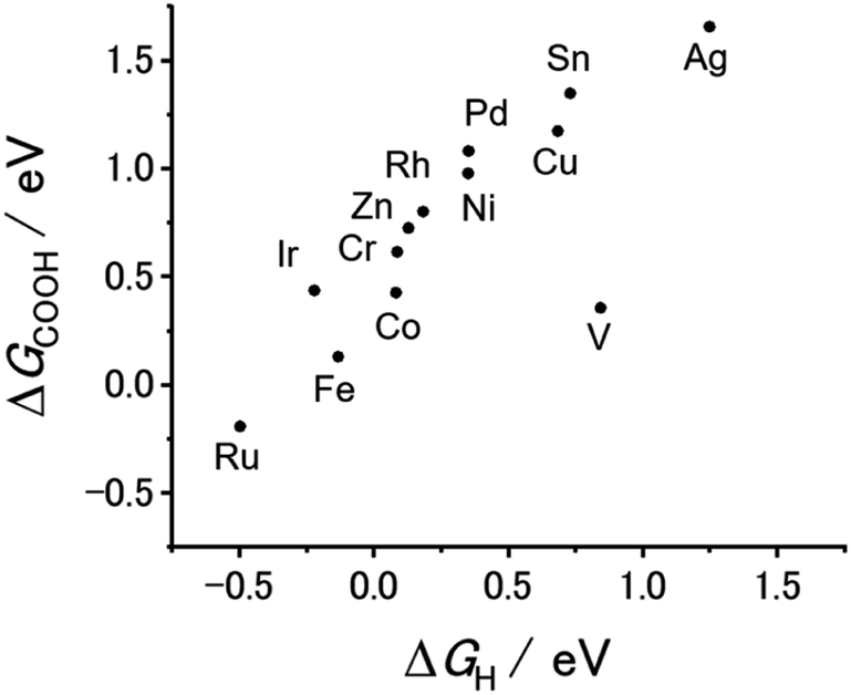 | ||
| Fig. 2 ΔGCOOH expressed in terms of ΔGH for each M-CTF. | ||
HCOOH is the other two-electron reduction product of CO2.77–82 Next, let us predict the selectivity of CO and HCOOH based on the DFT calculations. As shown in Fig. 1(c), 2, and S1,† there is a linear relationship between ΔG(COOH), ΔG(CO), and ΔG(H). In this case, ΔG(COOH), ΔG(CO), and ΔG(H) can serve as the descriptor of the selectivity not only for CO2RR against HER but for CO vs. HCOOH formation. When the adsorption of these reactive species becomes weak (i.e., ΔG values shift to the positive side), a major product gradually changes H2 to CO, and then to HCOOH. We must note that reactive species for which adsorption energy serves as a descriptor are not necessarily reaction intermediates, which means this prediction does not suggest COOH*, H* or CO* is the intermediate for HCOOH production. In many reports, the key intermediates in the production of CO and HCOOH are COOH* and OCHO*, respectively.79–82 The surface with a high affinity to COOH or H facilitates CO or H2 evolution, respectively. Therefore, the large negative potential needed for HCOOH production can be applied without CO and H2 formation only when the binding energy of both COOH and H (and CO) is weak,72,76 which is the reason why we can utilize ΔG(COOH), ΔG(CO) or ΔG(H) as the descriptor for the selectivity. Based on this classification, we expected that CO and HCOOH become the main products on M-CTFs with moderate ΔG (Ni-, Cu-, and Co-CTFs) and those with high ΔG (Sn-CTF), respectively. Among them, the highest ΔG for Ag-CTF does not correspond with the trend of reported SAECs.63,74,82 The stability test of single atom sites using DFT calculations revealed that Ag-CTF exhibited the lowest stability of single atoms in M-CTF (for the detail, see Table S2† and its caption); there might be some inconsistency between the genuine and model structures for Ag-CTF. Thus, the experimental results for Ag-CTF are shown as the reference data in Fig. S2,† and we need further studies to clarify the reason for this mismatch.
We next attempted to experimentally determine the CO2RR activity for the M-CTF/GDEs. The CTF was synthesized by polymerizing 2,6-dicyanopyridine in molten ZnCl2 containing carbon nanoparticles. The resultant CTF was impregnated with various metal chloride or acetate solutions to obtain M-CTFs (M = Ag, Co, Cu, Ni, Fe, Ru, Sn). Details of the synthesis conditions are provided in the ESI.†
Table S3† lists the surface elemental composition for the M-CTF/GDEs, which was measured by X-ray photoelectron spectroscopy (XPS). The metal amounts in the M-CTF/GDEs are between 0.09 and 0.32 at%. Detailed characterization results for the powder forms of the Ni-, Cu-, and Co-CTFs are provided in our previous reports.48,83 The XPS and X-ray absorption fine structure (XAFS) results for these M-CTFs deposited onto GDEs are shown in Fig. 3(a) and S3–S5,† respectively. The results are basically consistent with those for the corresponding powder samples. The curve fitting of EXAFS spectra for Ni-CTF was conducted (Fig. S6† and Table S4†). Notably, the coordination numbers (CNs) of Ni-CTF was 3.4, which is smaller than that of 5,10,15,20-tetraphenyl-21H,23H-porphine Ni (Ni-TPP, i.e., Ni–N4 macrocycle). This result corresponds to the previous results and suggest that M-CTF possess M–N3 structure.48
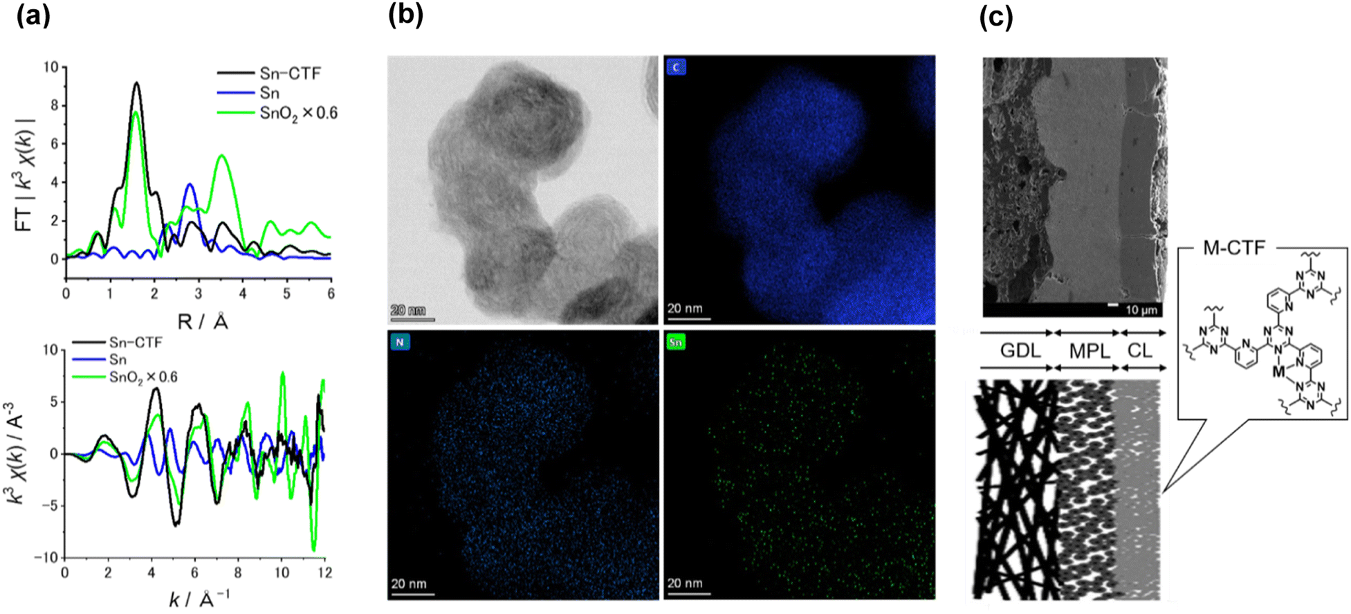 | ||
| Fig. 3 (a) (upper) k3-Weighted FT-EXAFS spectra and (bottom) k-plot spectra of Sn-CTF and reference samples. (b) Representative HR-TEM image of Sn-CTF and corresponding EDX mapping images for C, N, and Sn atoms. The scale bar in all the images is 20 nm. (c) (left upper) Cross-sectional SEM image of Ni-CTF/GDE, which shows gas diffusion layer (GDL), micro-porous layer (MPL), and catalyst layer (CL), and (left bottom) schematic of cross-section of M-CTF/GDEs, and (right) structure of M-CTFs. Scale bar is 10 μm. | ||
The present paper describes the detailed properties of Sn-CTFs. Fig. S3 and S4(b)† show XPS and X-ray absorption near edge structure (XANES) spectra, respectively, of the Sn-CTF/GDE. The narrow XPS spectrum shows the Sn 3d5/2 peak at 487 eV, which indicates that SnIV was dominant in the Sn-CTF/GDE;84 this interpretation was confirmed by the XANES spectra (for details, see the ESI†). Extended X-ray absorption fine structure (EXAFS) spectra for the Sn- and Ni-CTFs are shown in Fig. 3(a) and S5,† respectively. In the Fourier transformation of the k3-weighted EXAFS oscillations for the Sn-CTF (Fig. 3(a)), peaks corresponding to Sn–Sn bonds (2.9 Å) in Sn particles and Sn–O–Sn bonds (3.3 Å) in SnO2 were not observed. High-resolution energy-dispersive X-ray (HR-EDX) mapping and high-angle annular dark-field scanning transmission electron microscopy (HAADF-STEM) images of the Sn-CTF are shown in Fig. 3(b) and S7,† respectively. Fig. 3(b) shows Sn atoms as small white spots (smaller than 0.5 nm). These results indicate that the SnIV atoms were singly isolated in the as-prepared Sn-CTF. Scanning electron microscopy (SEM) images of cross-sections of the Ni-CTF/GDE are shown in Fig. 3(c) and S8.† The 50 nm catalyst particles were pasted onto a microporous layer composed of carbon nanoparticles. The thickness of the catalyst layers was ∼30 μm. The SEM observations showed no specific characteristics that depended on the metal species in the M-CTF/GDEs.
We analyzed the products of the CO2RR conducted in the presence of the M-CTF/GDEs. As shown in Fig. S9,† the M-CTF/GDEs enabled high-rate electrolysis at a current density greater than −100 mA cm−2. Fig. 4(a), (b) and S10† show the breakdown of the CO2 reduction products of the M-CTFs under a constant potential of −0.9 V vs. reversible hydrogen electrode (RHE) in 1 M KHCO3(aq) (pH 8.6). Only H2, CO, and HCOOH were detected on all the M-CTF/GDEs, and no further reduction products were observed (Fig. S11 and S12†). The Ni- and Co-CTFs produced CO as the main product of the CO2RR, whereas HCOOH was mainly generated on the Sn-CTF, consistent with the predictions based on DFT calculations (Fig. 2). In contrast, the HER, which competes with the CO2RR, was the main reaction for the Ru- and Fe-CTFs. The FE for CO reached greater than 98% for the Ni-CTF/GDE. However, the FE for HCOOH was 80% for the Sn-CTF/GDE. These results indicate that the selectivity of the CO2RR strongly depends on the metal species of the M-CTF. In the case of the Ni- and Sn-CTFs, we conducted XAFS characterizations after electrolysis to identify the active sites for high-rate CO2RR (Fig. S13†). The Fourier transformed EXAFS (FT-EXAFS) spectra of the M-CTF/GDEs after electrolysis still showed no obvious peaks corresponding to M–M and M–O–M bonds attributed to metal particles and oxides, respectively. These results indicate that the active sites for high-rate CO2RR were single metal atoms coordinated to CTFs.
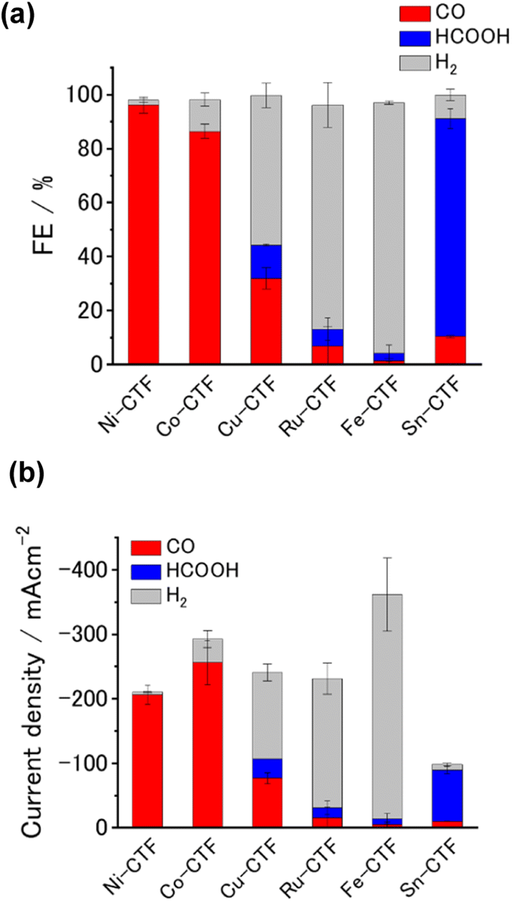 | ||
| Fig. 4 (a) FE, (b) current density breakdown for products of CO2 electrolysis in the presence of M-CTFs (M = Ni, Co, Cu, Ru, Fe, Sn). Potential: −0.9 V vs. RHE; electrolyte: 1 M KHCO3(aq) (pH 8.6). The error bars represent the standard deviations obtained from three experimental trials. | ||
We next investigated the potential window and the current density for the CO2RR on the Ni- and Sn-CTF/GDEs. Fig. 5(a) and (b) show the potential dependence of the FE and the partial current densities on the Ni-CTF/GDE, respectively. The FE for CO production (FECO) was greater than 98% between −0.5 and −0.9 V vs. RHE (Fig. 5(a)). Fig. 5(b) and S14† shows that the partial current density for CO generation (jCO) was maximized at −0.9 V vs. RHE and reached jCO = −200 mA cm−2. The onset potential for the competing HER was −0.9 V vs. RHE, and the faradaic efficiency for H2 production (FEH2) increased, accompanied by a negative potential shift. In the case of the Sn-CTF, the FEHCOOH and the partial current density for formate generation with the Sn-CTF/GDE reached 85% at −1.0 V vs. RHE and jHCOOH = −150 mA cm−2 at −1.2 V vs. RHE (Fig. 5(c) and (d)). We conducted the stability tests for Sn-, Ni- and Co-CTF/GDEs. Fig. S15–S17† show that Sn-, Ni- and Co-CTF on GDE had a negligible decrease in the FE for CO2RR for several hours. In addition, Sn- and Co-CTFs show an almost constant partial current density within this time scale. However, a 20% decrease in CO partial current density after 2 h was observed for Ni-CTF. The desorption of Ni atoms would be the main reason for the current decrease (for the detail, see Fig. S18, S19 and the caption in Fig. S16†). The appropriate choice of frameworks is required to improve stability, which is ongoing in our laboratory.
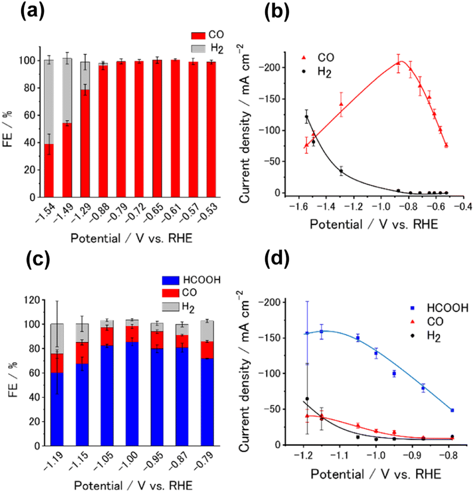 | ||
| Fig. 5 Potential dependence of (a) FE and (b) partial current density for Ni-CTF/GDE in 1 M KHCO3(aq) (pH 8.6). Potential dependence of (c) FE and (d) partial current density for Sn-CTF/GDE in 1 M KHCO3(aq) (pH 8.6). The error bars represent the standard deviations obtained from three experimental trials. | ||
Although the adsorption strength of reaction intermediates is known to be an essential factor influencing the CO2RR, systematic studies of the relationship between the adsorption strength and experimental activity under high-current conditions have not been reported. Given the previously discussed theoretical and experimental results, our M-CTFs are a suitable class of electrocatalysts for investigating the relationship between the adsorption strength and experimental activity because of their wide variety of available single-metal sites with high CO2RR activity. Thus, we here discuss the dependency of the CO generation rate on the adsorption strength of intermediates under high-rate CO2RR conditions.
Fig. 6 and S20† show the jCO at −0.9 V vs. RHE against ΔG(COOH) and ΔG(CO), respectively. As demonstrated in Fig. 1(c), there is a linear relationship (scaling relationships) between ΔG(COOH) and ΔG(CO), meaning that ΔG(CO) decreases with decreasing ΔG(COOH). Therefore, only ΔG(COOH) (or ΔG(CO)) can serve as the descriptor for both COOH* formation and CO desorption steps.85,86 A volcano-type relation with a single peak located near the data points for the Co- and Ni-CTFs was obtained. Fig. 1(d) shows that the Co-, Fe- and Ru-CTFs bind both CO and COOH too strongly (>0.50 eV), whereas the adsorption strength of these intermediates on the Sn- and Cu-CTFs was 0.37 and 0.20 eV weaker than the optimal value of ΔG(COOH), respectively. As explained in the theoretical section, the desorption of CO and formation of COOH was the potential-determining step for M-CTFs at the lower and higher ΔG sides, respectively. On the basis of the Sabatier principle, an appropriate binding energy for key intermediates, which is neither too strong nor too weak, leads to maximum activity.68,87 As shown in Fig. 6 and S20,† a volcano-type relation was observed for the M-CTF/GDEs. These results indicate that the CO generation rate was clearly dependent on the adsorption strength of intermediates even under high-rate CO2RR conditions. As for Co-, Fe- and Ru-CTFs, ΔG(COOH) was lower than the optimal value, meaning that CO adsorption was too strong, and its desorption became the potential determining step. By contrast, COOH* formation became the potential-determining step for Cu-CTF with the higher ΔG(COOH). This is the first study on the relationship between adsorption strength and high-rate CO2RR activity.
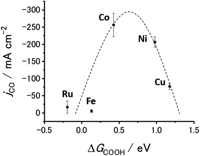 | ||
| Fig. 6 Partial current density for CO generation as function of adsorption energy of COOH to M-CTFs (M = Co, Cu, Ni, Fe, Ru). Potential: −0.9 V vs. RHE; electrolyte: 1 M KHCO3(aq) (pH 8.6). The error bars represent the standard deviations obtained from three experimental trials. | ||
As predicted about the selectivity between CO and HCOOH, Ni- and Co-CTFs with moderate ΔG and Sn-CTF with high ΔG produced CO and HCOOH, respectively (Fig. 1(c), 2 and S1†). When the adsorption of both COOH and H is weak, HCOOH formation becomes dominant, which corresponds to the reported selectivity.75,76 We can also explain the selectivity between CO2RR and HER. As previously reported and explained in the DFT parts,75,76 a strong H- or COOH-adsorption is known to cause the HER selectivity against CO2RR. Even for our M-CTFs, Fe- and Ru-CTFs exhibited stronger adsorption than others (Fig. 1(c), 2 and S1†) and showed that the HER was preferable to CO2RR. In contrast, other M-CTFs showed that CO2RR was dominant, which clearly corresponded to the DFT results. Thus, the product selectivity can be strongly modulated by changing the metal center, which controls the adsorption energy of the intermediate even under high-current electrolysis conditions.
These results show that the M-CTFs can be used to systematically and precisely control the adsorption energy when only the metal species is changed, even under high-rate electrolysis. The results therefore suggest that M-CTFs are an ideal platform catalyst material for high-rate electrolysis using GDEs, which is not limited to CO2 electrolysis. The M-CTFs are also expected to serve as model catalysts for establishing catalyst design guidelines specialized for high-rate electrolysis.
Conclusions
In this study, we successfully used M-CTFs as selective and high-rate CO2RR catalysts. The Ni- and Sn-CTFs produced CO and HCOOH on GDEs, which corresponded closely to the CO2RR intermediate adsorption strength obtained by DFT calculations. Our results indicate that the molecular-scale design of M-CTFs can affect the CO2RR activity with a current density greater than −100 mA cm−2. This is the first systematic study of SAECs for high-rate electrolysis of gaseous CO2. Thus, our results provide a design direction for efficient catalysts for high-rate CO2RRs. In addition, our M-CTFs will serve as a platform for electrocatalysts on GDEs, comparable to metal nanoparticles and metal macrocycles.Data availability
The data that support the findings of this study are available from the corresponding author upon reasonable request.Author contributions
S. N. and K. K. conceptualized the project. S. K. and T. Y. H. synthesized M-CTFs, conducted the CO2RR performance tests, and performed the DFT calculations. S. K. and T. S. H. designed the experiment. S. K. and K. I. performed the characterization of M-CTF/GDEs and analyzed the related data. S. K., K. I. and K. K. wrote the manuscript. S. N. and K. K. co-supervised the whole project. All authors discussed the results and commented on the manuscript.Conflicts of interest
There are no conflicts to declare.Acknowledgements
This work was supported by a JSPS KAKENHI Program (grants 21J22493, 22H02175, and 20H02568) and CREST (grant JPMJCR18R3) of the Japan Science and Technology Agency. Synchrotron radiation experiments were performed using the BL01B1 beamline of SPring-8 with approval of the Japan Synchrotron Radiation Research Institute (proposals 2020A1426, 2021A1294, 2021B1204, and 2022A1165). A part of this study was supported by the Center for Integrated Nanotechnology Support, Tohoku University, sponsored by the Ministry of Education, Culture, Sport, Science and Technology, Japan (grant A-20-TU-0023). We also acknowledge Dr Y. Hayasaka and Ms S. Nakahata for the HR-TEM observation and experimental support, respectively.Notes and references
- G. Wang, J. Chen, Y. Ding, P. Cai, L. Yi, Y. Li, C. Tu, Y. Hou, Z. Wen and L. Dai, Chem. Soc. Rev., 2021, 50, 4993–5061 RSC.
- A. R. Woldu, Z. Huang, P. Zhao, L. Hu and D. Astruc, Coord. Chem. Rev., 2022, 454, 214340 CrossRef CAS.
- Y. Ding, J. R. Bertram, C. Eckert, R. R. Bommareddy, R. Patel, A. Conradie, S. Bryan and P. Nagpal, J. Am. Chem. Soc., 2019, 141, 10272–10282 CrossRef CAS PubMed.
- E. Sediva, A. J. Carrillo, C. E. Halloran and J. L. M. Rupp, ACS Appl. Energy Mater., 2021, 4, 1474–1483 CrossRef CAS.
- Y. Kuramochi, O. Ishitani and H. Ishida, Coord. Chem. Rev., 2018, 373, 333–356 CrossRef CAS.
- S. Jin, Z. Hao, K. Zhang, Z. Yan and J. Chen, Angew. Chem., Int. Ed., 2021, 60, 20627–20648 CrossRef CAS PubMed.
- A. Sacco, R. Speranza, U. Savino, J. Zeng, M. A. Farkhondehfal, A. Lamberti, A. Chiodoni and C. F. Pirri, ACS Sustainable Chem. Eng., 2020, 8, 7563–7568 CrossRef CAS.
- D. R. Kauffman, J. Thakkar, R. Siva, C. Matranga, P. R. Ohodnicki, C. Zeng and R. Jin, ACS Appl. Mater. Interfaces, 2015, 7, 15626–15632 CrossRef CAS PubMed.
- M. Kö, J. Vaes, E. Klemm and D. Pant, iScience, 2019, 19, 135–160 CrossRef PubMed.
- H. Rabiee, L. Ge, X. Zhang, S. Hu, M. Li and Z. Yuan, Energy Environ. Sci., 2021, 14, 1959–2008 RSC.
- S. Kato, K. Iwase, T. Harada, S. Nakanishi and K. Kamiya, ACS Appl. Mater. Interfaces, 2020, 12, 29376–29382 CrossRef CAS PubMed.
- H. Yang, Q. Lin, C. Zhang, X. Yu, Z. Cheng, G. Li, Q. Hu, X. Ren, Q. Zhang, J. Liu and C. He, Nat. Commun., 2020, 11, 593 CrossRef CAS PubMed.
- K. Pellumbi, M. Smialkowski, D. Siegmund and U. P. Apfel, Chem. - Eur. J., 2020, 26, 9938–9944 CrossRef CAS PubMed.
- A. Gawel, T. Jaster, D. Siegmund, J. Holzmann, H. Lohmann, E. Klemm and U. P. Apfel, iScience, 2022, 25, 104011 CrossRef CAS PubMed.
- S. Ren, D. Joulié, D. Salvatore, K. Torbensen, M. Wang, M. Robert and C. P. Berlinguette, Science, 2019, 365, 367–369 CrossRef CAS PubMed.
- A. Reyes, R. P. Jansonius, B. A. W. Mowbray, Y. Cao, D. G. Wheeler, J. Chau, D. J. Dvorak and C. P. Berlinguette, ACS Energy Lett., 2020, 5, 1612–1618 CrossRef CAS.
- A. Löwe, M. Schmidt, F. Bienen, D. Kopljar, N. Wagner and E. Klemm, ACS Sustainable Chem. Eng., 2021, 9, 4213–4223 CrossRef.
- A. Löwe, C. Rieg, T. Hierlemann, N. Salas, D. Kopljar, N. Wagner and E. Klemm, ChemElectroChem, 2019, 6, 4497–4506 CrossRef.
- M. C. O. Monteiro, S. Dieckhöfer, T. Bobrowski, T. Quast, D. Pavesi, M. T. M. Koper and W. Schuhmann, Chem. Sci., 2021, 12, 15682–15690 RSC.
- J. R. C. Junqueira, P. B. O'Mara, P. Wilde, S. Dieckhöfer, T. M. Benedetti, C. Andronescu, R. D. Tilley, J. J. Gooding and W. Schuhmann, ChemElectroChem, 2021, 8, 4848–4853 CrossRef CAS PubMed.
- P. Wilde, P. B. O'Mara, J. R. C. Junqueira, T. Tarnev, T. M. Benedetti, C. Andronescu, Y. T. Chen, R. D. Tilley, W. Schuhmann and J. J. Gooding, Chem. Sci., 2021, 12, 4028–4033 RSC.
- C. T. Dinh, F. P. García De Arquer, D. Sinton and E. H. Sargent, ACS Energy Lett., 2018, 3, 2835–2840 CrossRef CAS.
- C. M. Gabardo, A. Seifitokaldani, J. P. Edwards, C. T. Dinh, T. Burdyny, M. G. Kibria, C. P. O'Brien, E. H. Sargent and D. Sinton, Energy Environ. Sci., 2018, 11, 2531–2539 RSC.
- B. Endrődi, E. Kecsenovity, A. Samu, T. Halmágyi, S. Rojas-Carbonell, L. Wang, Y. Yan and C. Janáky, Energy Environ. Sci., 2020, 13, 4098–4105 RSC.
- B. Endrődi, A. Samu, E. Kecsenovity, T. Halmágyi, D. Sebők and C. Janáky, Nat. Energy, 2021, 6, 439–448 CrossRef PubMed.
- B. Endrödi, E. Kecsenovity, A. Samu, F. Darvas, R. v. Jones, V. Török, A. Danyi and C. Janáky, ACS Energy Lett., 2019, 4, 1770–1777 CrossRef PubMed.
- B. Endrődi, G. Bencsik, F. Darvas, R. Jones, K. Rajeshwar and C. Janáky, Prog. Energy Combust. Sci., 2017, 62, 133–154 CrossRef.
- N. T. Nesbitt, T. Burdyny, H. Simonson, D. Salvatore, D. Bohra, R. Kas and W. A. Smith, ACS Catal., 2020, 10, 14093–14106 CrossRef CAS.
- F. Pelayo García de Arquer, C.-T. Dinh, A. Ozden, J. Wicks, C. McCallum, A. R. Kirmani, D.-H. Nam, C. Gabardo, A. Seifitokaldani, X. Wang, Y. C. Li, F. Li, J. Edwards, L. J. Richter, S. J. Thorpe, D. Sinton and E. H. Sargent, Science, 2020, 367, 661–666 CrossRef PubMed.
- M. de Jesus Gálvez-Vázquez, P. Moreno-García, H. Xu, Y. Hou, H. Hu, I. Z. Montiel, A. v. Rudnev, S. Alinejad, V. Grozovski, B. J. Wiley, M. Arenz, P. Broekmann and P. Moreno-García, ACS Catal., 2020, 10, 13096–13108 CrossRef.
- T. Sau and A. Rogach, Adv. Mater., 2010, 22, 1781–1804 CrossRef CAS PubMed.
- S. Panigrahi, S. Kundu, K. Ghosh, S. Nath and S. Pal, J. Nanopart. Res., 2004, 6, 411–414 CrossRef CAS.
- G. Oskam, J. Solgel Sci. Technol., 2006, 37, 161–164 CrossRef CAS.
- P. Goulet and R. Lennox, J. Am. Chem. Soc., 2010, 132, 9582–9584 CrossRef CAS PubMed.
- K. An and G. Somorjai, ChemCatChem, 2012, 10, 1512–1524 CrossRef.
- A. Loiudice, P. Lobaccaro, E. Kamali, T. Thao, B. Huang, J. Ager and R. Buonsanti, Angew. Chem., Int. Ed., 2016, 55, 5789–5792 CrossRef CAS PubMed.
- M. Ma, K. Djanashvili and W. Smith, Angew. Chem., Int. Ed., 2016, 55, 6680–6684 CrossRef CAS PubMed.
- T. Zhang, X. Han, H. Yang, A. Han, E. Hu, Y. Li, X. Yang, L. Wang, J. Liu and B. Liu, Angew. Chem., Int. Ed., 2020, 59, 12055–12061 CrossRef CAS PubMed.
- S. Liu, H. Yang, S. Hung, J. Ding, W. Cai, L. Liu, J. Gao, X. Li, X. Ren, Z. Kuang, Y. Huang, T. Zhang and B. Liu, Angew. Chem., Int. Ed., 2020, 59, 798–803 CrossRef CAS PubMed.
- X. Li, H. Rong, J. Zhang, D. Wang and Y. Li, Nano Res., 2020, 13, 1842–1855 CrossRef CAS.
- Z. Liang, W. Guo, R. Zhao, T. Qiu, H. Tabassum and R. Zou, Nano Energy, 2019, 64, 103917 CrossRef CAS.
- P. Kuhn, M. Antonietti and A. Thomas, Angew. Chem., Int. Ed., 2008, 47, 3450–3453 CrossRef CAS PubMed.
- P. Kuhn, A. Thomas and M. Antonietti, Macromolecules, 2009, 42, 319–326 CrossRef CAS.
- R. Kamai, K. Kamiya, K. Hashimoto and S. Nakanishi, Angew. Chem., Int. Ed., 2016, 55, 13184–13188 CrossRef CAS PubMed.
- K. Iwase, T. Yoshioka, S. Nakanishi, K. Hashimoto and K. Kamiya, Angew. Chem., Int. Ed., 2015, 54, 11068–11072 CrossRef CAS PubMed.
- K. Kamiya, R. Kamai, K. Hashimoto and S. Nakanishi, Nat. Commun., 2014, 5, 5040 CrossRef CAS PubMed.
- K. Kamiya, Chem. Sci., 2020, 11, 8339–8349 RSC.
- P. Su, K. Iwase, T. Harada, K. Kamiya and S. Nakanishi, Chem. Sci., 2018, 9, 3941–3947 RSC.
- Y. Wang, J. Chen, G. Wang, Y. Li and Z. Wen, Angew. Chem., Int. Ed., 2018, 130, 13304–13308 CrossRef.
- C. Lu, J. Yang, S. Wei, S. Bi, Y. Xia, M. Chen, Y. Hou, M. Qiu, C. Yuan, Y. Su, F. Zhang, H. Liang and X. Zhuang, Adv. Funct. Mater., 2019, 29, 1806884 CrossRef.
- D. Huang, Q. Wang, W. Dong, L. Liao, H. Chen and J. Ye, Energy Fuels, 2022, 36, 11601–11608 CrossRef CAS.
- L. Gong, X. Wang, T. Zheng, J. Liu, J. Wang, Y. C. Yang, J. Zhang, X. Han, L. Zhang and Z. Xia, J. Mater. Chem. A, 2021, 9, 3555–3566 RSC.
- A. M. Patel, S. Ringe, S. Siahrostami, M. Bajdich, J. K. Nørskov and A. R. Kulkarni, J. Phys. Chem. C, 2018, 122, 29307–29318 CrossRef CAS.
- F. Zhou, X. Song, C. Hao and J. Qiu, ACS Appl. Energy Mater., 2022, 5, 825–831 CrossRef CAS.
- J. Artz, ChemCatChem, 2018, 10, 1753–1771 CrossRef CAS.
- K. Ohashi, K. Iwase, T. Harada, S. Nakanishi and K. Kamiya, J. Phys. Chem. C, 2021, 125, 10983–10990 CrossRef CAS.
- K. Iwase, S. Nakanishi, M. Miyayama and K. Kamiya, ACS Appl. Energy Mater., 2020, 3, 1644–1652 CrossRef CAS.
- X. Wei, S. Xiao, R. Wu, Z. Zhu, L. Zhao, Z. Li, J. Wang, J. S. Chen and Z. Wei, Appl. Catal., B, 2022, 302, 120861 CrossRef CAS.
- X. Li, S. Xi, L. Sun, S. Dou, Z. Huang, T. Su and X. Wang, Adv. Sci., 2020, 7, 2001545 CrossRef CAS PubMed.
- F. Calle-Vallejo, J. I. Martinez, J. M. Garcia-Lastra, J. Rossmeisl and M. T. M. Koper, Phys. Rev. Lett., 2012, 108, 116103 CrossRef CAS PubMed.
- J. Rossmeisl, A. Logadottir and J. K. Nørskov, Chem. Phys., 2005, 319, 178–184 CrossRef CAS.
- F. Abild-Pedersen, J. Greeley, F. Studt, J. Rossmeisl, T. R. Munter, P. G. Moses, E. Skúlason, T. Bligaard and J. K. Nørskov, Phys. Rev. Lett., 2007, 99, 016105 CrossRef CAS PubMed.
- V. Tripkovic, M. Vanin, M. Karamad, M. E. Björketun, K. W. Jacobsen, K. S. Thygesen and J. Rossmeisl, J. Phys. Chem. C, 2013, 117, 9187–9195 CrossRef CAS.
- C. Shi, H. A. Hansen, A. C. Lausche and J. K. Nørskov, Phys. Chem. Chem. Phys., 2014, 16, 4720–4727 RSC.
- A. A. Peterson and J. K. Nørskov, J. Phys. Chem. Lett., 2012, 3, 251–258 CrossRef CAS.
- K. Chan, C. Tsai, H. A. Hansen and J. K. Nørskov, ChemCatChem, 2014, 6, 1899–1905 CrossRef CAS.
- M. Anand and J. K. Nørskov, ACS Catal., 2020, 10, 336–345 CrossRef CAS.
- A. J. Medford, A. Vojvodic, J. S. Hummelshøj, J. Voss, F. Abild-Pedersen, F. Studt, T. Bligaard, A. Nilsson and J. K. Nørskov, J. Catal., 2015, 328, 36–42 CrossRef CAS.
- B. Hammer and J. K. Nørskov, Nature, 1995, 376, 238–240 CrossRef CAS.
- J. K. Nørskov, F. Abild-Pedersen, F. Studt and T. Bligaard, Proc. Natl. Acad. Sci. U. S. A., 2011, 108, 937–943 CrossRef PubMed.
- H. Huang, H. Jia, Z. Liu, P. Gao, J. Zhao, Z. Luo, J. Yang and J. Zeng, Angew. Chem., Int. Ed., 2017, 56, 3594–3598 CrossRef CAS PubMed.
- A. Bagger, W. Ju, A. S. Varela, P. Strasser and J. Rossmeisl, Catal. Today, 2017, 288, 74–78 CrossRef CAS.
- V. Tripkovic, M. Vanin, M. Karamad, M. E. Björketun, K. W. Jacobsen, K. S. Thygesen and J. Rossmeisl, J. Phys. Chem. C, 2013, 117, 9187–9195 CrossRef CAS.
- M. J. Cheng, Y. Kwon, M. Head-Gordon and A. T. Bell, J. Phys. Chem. C, 2015, 119, 21345–21352 CrossRef CAS.
- A. Bagger, W. Ju, A. S. Varela, P. Strasser and J. Rossmeisl, ChemPhysChem, 2017, 18, 3266–3273 CrossRef CAS PubMed.
- J. Hussain, H. Jónsson and E. Skúlason, ACS Catal., 2018, 8, 5240–5249 CrossRef CAS.
- J. S. Yoo, R. Christensen, T. Vegge, J. K. Nørskov and F. Studt, ChemSusChem, 2016, 9, 358–363 CrossRef CAS PubMed.
- W. J. Durand, A. A. Peterson, F. Studt, F. Abild-Pedersen and J. K. Nørskov, Surf. Sci., 2011, 605, 1354–1359 CrossRef CAS.
- N. Han, P. Ding, L. He, Y. Li and Y. Li, Adv. Energy Mater., 2020, 10, 1902338 CrossRef CAS.
- J. T. Feaster, C. Shi, E. R. Cave, T. Hatsukade, D. N. Abram, K. P. Kuhl, C. Hahn, J. K. Nørskov and T. F. Jaramillo, ACS Catal., 2017, 7, 4822–4827 CrossRef CAS.
- M. J. Cheng, Y. Kwon, M. Head-Gordon and A. T. Bell, J. Phys. Chem. C, 2015, 119, 21345–21352 CrossRef CAS.
- S. Back, J. Lim, N. Y. Kim, Y. H. Kim and Y. Jung, Chem. Sci., 2017, 8, 1090–1096 RSC.
- Y. Wu, K. Kamiya, T. Hashimoto, R. Sugimoto, T. Harada, K. Fujii and S. Nakanishi, Electrochemistry, 2020, 88, 359–364 CrossRef CAS.
- D. Barreca, S. Garon, E. Tondello and P. Zanella, Surf. Sci. Spectra, 2000, 7, 81–85 CrossRef CAS.
- A. A. Peterson and J. K. Nørskov, J. Phys. Chem. Lett., 2012, 3, 251–258 CrossRef CAS.
- C. Shi, H. A. Hansen, A. C. Lausche and J. K. Nørskov, Phys. Chem. Chem. Phys., 2014, 16, 4720–4727 RSC.
- M. Che, Catal. Today, 2013, 218–219, 162–171 CrossRef CAS.
Footnote |
| † Electronic supplementary information (ESI) available. See DOI: https://doi.org/10.1039/d2sc03754h |
| This journal is © The Royal Society of Chemistry 2023 |