 Open Access Article
Creative Commons Attribution 3.0 Unported Licence
Transport phenomena in solid phase synthesis supported by cross-linked polymer beads
Sebastián
Pinzón-López
ab,
Mathias
Kraume
b,
José
Danglad-Flores
 *a and
Peter H.
Seeberger
 ac
ac
aMax-Planck-Institute of Colloids and Interfaces, Department of Biomolecular Systems, Am Mühlenberg 1, 14476 Potsdam, Germany. E-mail: jose.danglad@mpikg.mpg.de; Peter.seeberger@mpikg.mpg.de
bDepartment of Chemical and Process Engineering, Technische Universität Berlin, 10623 Berlin, Germany
cInstitute of Chemistry and Biochemistry, Freie Universität Berlin, 14195 Berlin, Germany
First published on 23rd September 2023
Abstract
Solid phase synthesis (SPS) is a powerful tool for synthesizing oligomers, especially peptides, nucleic acids, and glycans. Since Merrifield developed solid phase peptide synthesis in 1963, organic chemistry and analytics have seen major advances. The need to optimize the process regarding cost, time, and energy consumption has renewed the research on previously overlooked transport phenomena. Here, we summarize the current understanding of momentum, heat, and mass transport in SPS reactors, highlighting the progress and identifying the urgent questions to be addressed.
1. Introduction
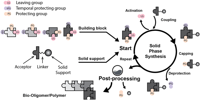
Solid phase synthesis (SPS) is a proven expedited method to access pure and well-defined polypeptides, polynucleotides, and polysaccharides.1–4 The synthesis of each biomolecule family follows a specific chemical strategy. Conditions such as solvent, temperature, reagent concentration, and basicity or acidity of the reaction environment change within the same process cycle.The technique (Fig. 1) depends on growing a molecular chain on a linker anchored to a solid support by the sequential (chemical) reaction of monomers or building blocks with the active sites on the solid support. In general terms, the second step of the cycle is opening a new active site on the attached chain; this occurs through the removal – or desorption – of a chemical moiety called the temporal protecting group (tPG). SPS reduces tedious purifications between iterative steps since the reactor facilitates the replacement of the liquid phase, removing any unreacted or released reagent from the solid support. The consecutive and repetitive nature of the process serves as an excellent platform for automation. Once the desired structure is completed, the molecule is cleaved from the beads via a chemical2,4 or photochemical reaction.5 Finally, any remaining protecting group(s) (PG) are removed to obtain the native compound. The tailor-made molecules enable fundamental research into their biological roles3 that later translate into applications such as vaccine development,6,7 therapeutics, and diagnostic tools.8
Initially, Merrifield2,9 established the method and illustrated its potential as an automated platform for peptide synthesis. Automated SPS was then implemented for DNA10 and later for glycan synthesis (known as automated glycan assembly or AGA).11 However, the contribution of mass transport has been neglected since the beginning.12 Optimization efforts instead focused on purely organic chemistry-related developments. Limited research13–20 indicates that mass transfer must be considered to get realistic modeling and to assess its contribution to the overall process.20,21
The need for further optimization regarding process time, cost, and yield, especially in AGA, has prompted renewed attention to the physical aspects of SPS, such as mixing and swelling.22–27 Glycans are branched structures where regio- and stereocontrol must be controlled throughout the synthesis. Consequently, carbohydrate building blocks are more complex and expensive than the precursors of linear molecules such as oligonucleotides and peptides. Excess building block23,28 and long reaction times promote chemical bond formation.3,24 Faster processing times and less reagent excess are desirable for automated SPS to reach its full potential. Recent strategies to achieve reaction acceleration included microwave radiation,24,29,30 dual temperature control systems,24 pre-heating the reagents,28,31 and high-shear mixing methods.25–27,32 However, little attention has been paid to formal modeling and understanding the transport phenomena behind such technological developments.
Here, we present a systematic overview of the research regarding the transport phenomena related to solid phase synthesis. We pay special attention to mass transfer, limiting this work to cross-linked polystyrene particles as solid support (typically 1% divinyl benzene, DVB, ∼150 μm mean dry diameter). We highlight the importance of understanding such phenomena in SPS as the base for process intensification; we start with an outline of the SPS technique in the following section.
2. Solid phase synthesis (SPS)
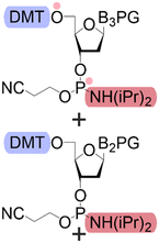
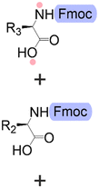
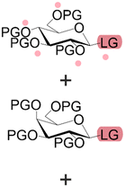
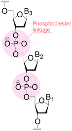
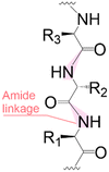
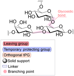
Bond formation (see Fig. 1 and Table 1) or coupling is the essential step during the process. The coupling agent (building block or electrophile) is activated upon the release of the leaving group and, once activated, is ready to form a chemical bond to the nucleophile attached to the solid support (to the matter of this review, an insoluble, functionalized, polymeric matrix to which reagents are connected via a linker33,34).| Nucleic acids | Peptides | Oligosaccharides | |
|---|---|---|---|
| a Most common solvent used in the coupling and activation step. b Cycle times can be influenced by numerous parameters; here, we present a range based on lower and upper limits found in the literature (for peptides, see: ref. 28 and 41–43; for nucleic acids, see: ref. 44–46; for glycans see: ref. 22, 24 and 32; Bakhatan et al.32 recently reported dimer formation with a cycle time of 8 min). c Obtained from equipment manufacturers (taking the upper limit).47–50 The scale could reach 3 kg for nucleic acids and peptides (the lab scale is hundreds of milligrams), while for glycans, the typical amount of product is 2 mg. The reactor's configurations are commonly slurry tanks or fixed beds of the solid support.22,23,28,50 Mixing utilizes N2 or Ar as bubbling gases or mechanical means such as shaking and stirring. | |||
| Building blocks |
|
|
|
| First building block on support |

|

|

|
| Structure |
|
|
|
| Linear | Linear | Branched | |
| Introduce in | 1981 | 1963 | 2001 |
| Solventa | ACN | DMF | DCM |
| Cycle timeb | (5–30) min | (2–30) min | (8–90) min |
| Coupling yield | ≈99.8% | ≈99.5% | ≈98.5% |
| Temperature range | 20 °C | [20, 100] °C | [−40, 100] °C |
| Scalec | ≈2.5 mol | ≈2.5 mol | ≈100 μmol |
| Reactor volumec | 1.5 L | 15 L | 10 mL |
| Mixingc | Mechanical/Ar | Mechanical/N2 | Ar |
Following coupling is the removal or deprotection of a tPG (temporary protecting group) that masks (protects) a reactive position on the attached molecule. The adequate reagent opens the next acceptor site on the solid support, typically at room or above room temperature. Then, the cycle can be repeated to install the next building block. Peptides and oligonucleotides are linear molecules, while glycans are branched, and each glycosidic linkage that connects two monosaccharides is a new stereogenic center, consequently demanding stereo- and regiocontrol (Table 1).
This coupling-deprotection cycle is repeated until the desired molecule is synthesized. Auxiliary reactions allow for the manipulation of the active sites by adding functional groups. For example, a capping reaction installs an acetyl group to prevent further growth of the side chain on unreacted active sites.35,36 Other functional groups add to the structural complexity of the molecule.37–39 During SPS, the purification is reduced to washing steps to remove previous reagents from the reaction system between each chemical manipulation.3 Still, solid supports can cause the process to be diffusion-dependent.13–15,21,40
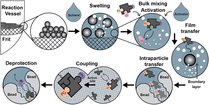
Parallel to the chemical process described above, relevant physicochemical and transport processes occur during the syntheses once the addition of the liquid phase forms a dispersed system (see Fig. 2): a) particle size variations due to swelling of the solid support by different solvents, b) particle dispersion through the liquid media, c) reagents mixing at the bulk liquid phase, d) temperature adjustment of the synthesis reagents, d) film diffusion d) in/out intraparticle transport of the chemical species, e) adsorption/coupling of chemical species on the active site, and g) deprotection of the temporal protecting group by the desorption of a functional group. Next, we discuss particle dispersion and bulk mixing.
3. Momentum transfer: mixing in SPS
Before the coupling step, the mixture of solutions containing the activator and building block is homogenized in the bulk liquid phase by the convective flow of the mixing (Fig. 2). Not much information is available regarding bulk-mixing for SPS, with manufacturers being the best reference and only specifying whether gas bubbling or mechanical methods are used.47–50 Gas bubbling also maintains an inert atmosphere in the reaction medium. In the case of packed beds, “active” flow distribution for “uniform dispersal of reagents across the entire column (bed) surface, even for columns packed with short bed heights” is assured for “maximum coupling efficiency”.50Quantitative data about the film (mass transfer) coefficients, mixing times, dispersion coefficients, or particle suspension are scarce. Also, there are no adequate quantitative comparisons between bubbling and mechanical mixing for SPS.51–53 Design guides for pilot-scale solid phase peptide reactors indicate that “agitation within a solid phase peptide slurry reactor must suspend resin particles, maintain homogeneity throughout the reactor and provide enough shear around the resin particles to limit (film) diffusion resistance. Film diffusion resistance may be minimal on particle sizes of 35–100 μm”.54
However, Stepaniuk et al.55 remarks that stirred-tank reactors (commonly used in SPPS) “suffer from certain limitations because as the beads are in suspension, the opportunities to increase the liquid velocity relative to the particles are extremely limited” because “the inertial and viscous forces imposed by the moving liquid tend to drag the particles along with it”. Packed beds and centrifugal reactors are a better option for higher relative velocities; Stepaniuk theoretically explains the impact of this on film diffusion.55
Similarly, the mixing methodology must minimize vortexing to avoid adhesion of the solid support to the reactor wall, and the fragility of the swollen beads also limits the mixing rate13,15 (nevertheless, mixing rates of around 1000 rpm have been reported without damage for the beads25).
Li and Yan56 compared several mixing methods in SPS using single bead infrared spectroscopy and fluorescence spectroscopy; the reaction studied was between formyl polystyrene resin (1% DVB, 75–150 μm) and dansyl hydrazine, with a total reaction time of 30 min. The best mixing methods were reported to be 180° rotation (16 rpm) and nitrogen bubbling (12 L min−1), with final yields above 99%. At the same reaction time, but without mixing, a final yield of 50% was obtained. This study provides a first point of reference rather than a detailed assessment of the mixing methods and the relative contribution of film diffusion in each case.
More recently, Bakhatan et al.,57 Naoum et al.,25,58 Alshanski et al.,26 and Strauss et al.27 reported higher yields in the SPS of peptides, glycopeptides, and glycans using mechanical stirring rather than gas bubbling; this improvement is attributed to the fact that mechanical stirring “increases the diffusion of both reagents and beads in a narrow dimension reactor”.25 No distinction between external and internal diffusion was made. The comparison seems arbitrary as conditions affecting mixing by bubbling (e.g., gas flow) are not specified. Another aspect of SPS that has been overlooked in the literature is the force balance that describes the dispersion of the particles in liquid media. A comprehensive investigation regarding the scale of the reaction and the relative properties of the solid/liquid dispersion is still needed to define the most efficient mixing method. Translating observations into a general diagram for the mixing scenario is laborious, but it is a fundamental tool missing for designing and scaling up SPS reactors.
To the best of our knowledge, an integrated assessment of SPS in packed bed reactors is still missing. Experiments have shown that a significant excess of reagents is required for reactions in packed beds to be efficient;22,23,28,43 scale-up can be problematic due to the high-pressure drop and dispersion (channeling) in the packed bed.
The contributions from dispersion, film, and intraparticle diffusion on the final yield of the synthesis have been highlighted and theoretically discussed in reports by Scott et al.20 for SPPS in packed beds, based on the band broadening theory for chromatography.59
4. Heat transfer: temperature adjustment
In SPPS, cycle times have been shortened, and yields improved using elevated temperatures (up to 100 °C) for the coupling during peptide syntheses, deprotection, and washing steps.29,41,48,60–62 Microwave heating was investigated in depth as the dielectric heating mechanism (molecular dipole rotation) was considered a non-thermal beneficial contributor for synthesizing so-called “difficult sequences”. However, for the synthesis of peptides up to 24-mers, Bacsa et al.41 found no practical differences in the synthesis output between conventional heating and microwave heating; the importance of a homogeneous temperature inside the reaction vessel was discussed as well.60,61 For an in-depth review of microwave heating in SPPS, see Pedersen et al.60Heating-related issues encouraged the use of pre-heating units for packed bed reactors. Mijalis et al.28 proposed a tubular pre-heating and pre-activation loop for SPPS: by separating activation and coupling steps, by-product formation and degradation of intermediates are minimized.28,62 Spare et al.63 used a similar approach, and despite requiring longer coupling times when compared to Mijalis et al.28 setup (7 s vs. 90 s), the building block excess is diminished by a factor of two.
In the case of AGA (see Table 1), due to building block reactivity and to suppress undesired side reactions, the temperature range in a cycle goes from sub-zero temperatures to elevated temperature24 (∼60 °C); this is a riveting technical challenge.
Using microwave heating to accelerate the capping and deprotection steps during AGA (AGA-MW), the cycle time decreased from ∼100 min to ∼55 min.24 A pre-cooling stage for reagents was added to AGA-MW to ensure better temperature control and avoid thermal peaks during reagent delivery. These thermal peaks can induce undesired side reactions, reduced by slow injection with syringe pumps but requiring as much as 9% of the total cycle time.24
A delivery method that finds an optimal trade-off between thermal peaks and delivery time to improve the system in speed and yield remains elusive. Similarly, although the reaction vessel is relatively small (approx. 10 mL reaction volume), the total volume of the thermal fluid is on the order of several liters; this poses engineering questions not only about the required time to cool down the entire system (around 10–30 min per cycle) but concerning the energy efficiency of the entire process.
For a better illustration, consider a reaction vessel containing 10 mL CH2Cl2 as the reaction media. To cool down this from 20 °C to −20 °C in 10 s, the required energy flow rate would be around 100 W when losses or resistances are not considered, while the nominal capacity of the current chillers is about 1000 W, and the cooling time is about 600 s.24 It is important to note that reaction vessels are usually made of materials with low thermal conductivity, such as glass or chemical-resistant polymers. To access temperatures below −20 °C, extensive and costly circulation thermostats have been used.24 Further improvements in reactor design (energy consumption and price reduction) require a rational understanding of the physicochemical consequences of process temperature adjustment and stability.
Having looked at how mixing strategies and heat transfer impact cycle time and overall performance in SPS, our next step is to discuss mass transfer. In the upcoming section, we will review studies on external (film) transfer and diffusion coefficient determination and explore the mathematical modeling of SPS.
5. Mass transfer: reagent transport
5.1. Film (external) diffusion
The diffusion of the reagents in the outer boundary layer formed around the particles (see Fig. 2) was discussed in section 3. For SPPS, Merrifield stated that the rate of mass transfer for Boc-Phe into the beads was 15 times higher than the reaction rate for the coupling reaction of Bpoc-Phe using a modified cross-linked (1%) polystyrene resin (Val-resin; 50 μm).12 However, this affirmation is unclear as it does not distinguish between film and intraparticle diffusion. Furthermore, a mathematical description or a clear physical framework was not provided to understand how the mass transfer rate was estimated.Merrifield was probably referring to film diffusion, which can be important when intraparticle diffusion is relatively fast or when the mixing strategy is not efficient.64 Film diffusion becomes a critical resistance to the overall process rate in systems with insufficient mixing. Inglezakis et al.64 reports that mass transfer coefficients below 10−3 cm s−1 are the product of incomplete suspension of solid particles, and a more thorough analysis is required to assess the predominance of the film-diffusion step.
Chen and coworkers13,15 discussed the relationship between mixing rate and film diffusion resistance by studying the effect of mixing rate in poly(Phe) synthesis using a cross-linked (2%; 40–75 μm) polystyrene resin. Changing the mixing rate from 100 rpm to 200 rpm did not affect the coupling rate, concluding that film diffusion was not a rate-limiting step. Nevertheless, the researchers concluded that a broader range of mixing rate values is needed for an adequate assessment.
For agitated vessels and bubble columns, the correlation developed by Sano et al.51 (theoretically supported by Kolmogoroff's turbulence theory) works as an initial estimate for film coefficients. It is also a correction for the Ranz and Marshall equation (Frössling correlation55,65). The latest estimates the film coefficient in packed beds. Comparing the film diffusion for packed bed reactors with the stirred tank counterparts (mechanically mixed and bubbled) would be beneficial while initially assessing the reactor configuration; film diffusion can also be weighed for packed beds using the band broadening theory.20
5.2. Diffusion coefficient measurement
Fick's first law defines the diffusion coefficient as the “quantitative measurement at which a diffusion process occurs”.66 Therefore, for any given solute in any given solvent, the knowledge of its diffusion coefficient is crucial for modeling and predicting how this phenomenon will evolve. In the case of a swollen polymer network, the diffusion coefficient of any given solute is typically “corrected” to account for the presence of the polymer. Reliable experimental data on diffusion coefficients (both in the solvent and the swollen polymer network) are essential if the diffusion contribution is to be properly assessed in SPS.Regarding cross-linked polystyrene, Roucis and Ekerdt67,68 investigated the diffusion of cyclic hydrocarbons in swollen benzene beads (800–1000 μm; 1–3% cross-linking), finding values for the diffusion coefficients between 0.51 × 10⁻⁶ and 5.89 × 10⁻⁶ cm2 s−1 (at 25 °C) and an inversely proportional relationship between the diffusion coefficient and degree of cross-linking.
By using magnetization-transfer NMR (MT-NMR), Ford et al.69 determined the self-diffusion coefficients -which can be viewed as “the mobility of the molecules concerning the stationary solution”66 – of solvents in swollen 1–20% cross-linked polystyrene beads (83–408 μm) at room temperature (23 to 25 °C) and compared the values with those obtained for diffusion in bulk liquids and in macroporous ion exchange resins. The DCM self-diffusion coefficient strongly depends on the polymeric cross-linking. It decreases from 17 × 10−6 (1% cross-linking) to 5.7 × 10⁻⁶ cm2 s−1 (10% cross-linking), and its value is never higher than half of the value obtained in the pure bulk liquid (36 × 10−6 cm2 s−1). Remarkably, the values for diffusion coefficients in ion exchange resins are in the same order of magnitude as those obtained for 1–6% cross-linking degree, and the difference is, in some cases, less than 6%. The researchers argue that DCM resides in the permanent pores and a slightly swollen zone in this polymeric network.
Using diffusion-ordered spectroscopy (DOSY), Gambs et al.70 compared the diffusion processes in JandaJel (J) and Merrifield (M) resins (75–150 μm; ∼1.4 mmol g−1) at 30 °C. They first assessed the diffusion of solvents (THF, DMF, and toluene), finding that the self-diffusion coefficient in solution is always higher, and the self-diffusion coefficients are higher for the (J) resin.70 For example, for DMF, the self-diffusion coefficient in solution is 30.5 × 10⁻⁶ cm2 s−1; in J-OH, it is 17.8 × 10⁻⁶ cm2 s−1, and in M-OH is 14.0 × 10⁻⁶ cm2 s−1; the higher diffusion coefficients in J resin are related to higher swelling ratios.
Gambs et al.70 studied the diffusion of small molecules in DMF-d7. For Boc-glycine methyl ester, the diffusion coefficient in the solvent is 9.8 × 10⁻⁶ cm2 s−1, while for J-OH and M-OH resins, the values are 3.6 × 10⁻⁶ cm2 s−1 and 2.5 × 10⁻⁶ cm2 s−1, respectively. When comparing these values for the diffusion of p-xylene, Gambs et al. observed that the “reduced” diffusion coefficient (the D value in the resin divided by the D value in solution) was similar for both components, showing that an increase in the hydrodynamic volume by a factor of two is not significant relative to the pore size of the resins.
Pickup et al.71 investigated the self-diffusion of toluene in cross-linked polystyrene (5.7–40%; 150–250 μm) at 25 °C. As before, increasing the cross-linking degree will decrease the diffusion coefficient from 4.57 × 10⁻⁶ (5.7% cross-linking) to 1.45 × 10⁻⁶ cm2 s−1 (40% cross-linking); Pickup et al. point out that the values for the diffusion coefficients in cross-linked beads are similar to those obtained in polymer solutions; for example, for a 40% cross-linking degree, and with the obtained swelling degree, he computes the weight fraction of polymer in the network and a corresponding diffusion coefficient for a solvent-linear polymer solution. The measured diffusion coefficient for a 20% cross-linking degree is 1.35 × 10⁻⁶ cm2 s−1, remarkably close to the calculated value72 for the equivalent linear-polymeric solution: 1.40 × 10⁻⁶ cm2 s−1.
With a clear focus on solid-phase peptide synthesis, Pickup et al.73 investigated the self-diffusion coefficients of protected amino acids in DCM-swollen cross-linked polystyrene beads (150–250 μm) at 23 °C. The values range from 5.30–6.86 × 10⁻⁶ cm2 s−1. The diffusion coefficients are 50% lower than in pure solvents. For the amino acids studied, the diffusion coefficient values follow the order Boc-Gly (175 g mol−1) > Boc-Ala (189 g mol−1) > Boc-Phe (265 g mol−1).
Likewise, using protected amino acids as molecular probes, Yamane et al.74 determined two components (slow and fast) in the diffusion of these molecules in cross-linked polystyrene with DMF-d7 as solvent by pulsed-field-gradient spin-echo 1H NMR. More than the diffusion coefficient values per se, the key insight of this investigation is that for the reference system, within the observation time, amino acids have multiple components of diffusion (slow and fast) that are the product of strong and weak intermolecular interactions between the amino acids and the polystyrene network. As expected, slow-diffusion components are lower at a lower swelling ratio, indicating that such intermolecular interactions depend strongly on the intermolecular distance. The authors elucidate this by computing the activation energy of diffusion for Boc-Gly at two swelling ratios (1.50 and 2.45). Their hypothesis seems confirmed by a sharp decrease in this activation energy, going from 9.50 to 5.34 kcal mol−1. For 1% cross-linked polystyrene, the diffusion coefficient values in DMF-d7 are around 15 × 10−7 cm2 s−1.
Yankov75 studied the diffusion of maltose and glucose in water-swollen polyacrylamide and found that the diffusion coefficient inside the gel was as low as 15% of that found in water. One interesting outcome is that the diffusion coefficient in the gel is not affected by the solute concentration, maintaining a relatively constant value (9.5 × 10⁻⁶ cm2 s−1 for glucose and 6.5 × 10⁻⁶ cm2 s−1 for maltose) for a range of concentrations ranging from 30 g L−1 to 200 g L−1.
However, other factors, such as the degree of cross-linking and the temperature, have a significant effect; an increase of cross-linking from 1% to 10% reduces the glucose diffusion coefficient from 9.24 × 10⁻⁶ cm2 s−1 to 2.59 × 10⁻⁶ cm2 s−1, similarly, increasing the temperature from 20 to 60 °C will increase this value from 4.63 × 10⁻⁶ cm2 s−1 to 10.9 × 10⁻⁶ cm2 s−1. Interestingly, immobilizing glucoamylase in the gel (10% weight fraction) resulted in a decrease in the diffusion coefficient for glucose from 9.24 × 10⁻⁶ to 6.98 × 10⁻⁶ cm2 s−1. The diffusion coefficients of sucrose and glucose in water were 0.70 × 10⁻⁶ and 4.65 × 10⁻⁶ cm2 s−1.
In general, for swollen polymer beads, the Mackie–Meares model can give an initial estimation of the diffusion coefficient of a solute inside the bead (D) if the value for the pure solvent (D0) is available:67,68,76,77
 | (1) |
Measuring the intraparticle diffusion coefficient is a difficult task subjected to a multifactorial system that should consider the diffusing molecule, the solvent or liquid media, the polymer network, and temperature. A simplified platform would be desirable for gathering the necessary data to feed general descriptive models like the ones described in the next section.
5.3. Intraparticle diffusion: modeling and experimental data
“Diffusion is not simple”;78 the need for practical and easy-to-implement equations has extended the use of Fick's first law. However, this law has several limitations: diffusion can counteract the concentration gradient and be a product of osmotic pressure and/or electrical effects. For mass transfer modeling, Wesselingh78 describes the generalized Maxwell–Stefan (GMS) approach as “a more comprehensive framework”. Since polymer beads in SPS are no longer considered “black boxes”,21 we discuss some studies regarding the matter, and while a Fickian approach is the most common model, it is essential to consider more general theories.Chen and coworkers13–15,40 proposed a comprehensive solid phase peptide synthesis (SPPS) model and segregated film and intraparticle diffusion (see section 3 and section 5.1). Chen investigated the effect of cross-linking degree in the coupling reaction for synthesizing resin–(Phe)n.13,14 For n = 1, 2, and 3, the second-order reaction constant reduced its value by one order of magnitude when the cross-linking degree increased from 1 to 2%; for example, for n = 3, the constant went down from 4.20 to 0.49 L mol−1 s−1. The reaction rate expression is:
 | (2) |
 | (3) |
Non-considerable intraparticle diffusion for initial values of n accords with experimental data from Pickup et al.73 for the coupling reaction of Bpoc-Gly, Bpoc-Ala, and Bpoc-Phe with modified Merrifield resins (Ala-Resin and Val-Resin; 45 μm, DCM-swollen). The times to reach 99% conversion are at least five times longer than those required to achieve 99.99% diffusion equilibrium (<3.0 s), indicating that the process is reaction-controlled.
Nevertheless, it is essential to note that the time for diffusion was a theoretical computation using experimental values for the (self) diffusion coefficients,73 and the required time for the reactions is extrapolated from a second-order kinetic model.12 Pickup – in evident contradiction to Chen and coworkers13–15,40 – states that for larger molecules attached to the solid support, the effect of diffusion should not be that significant, as the decrease in the diffusion coefficient would be by a factor of two in the worst scenario; this last assumption is based on the fact that for DCM the diffusion coefficient in 6% cross-linked beads is half the value observed in 1% cross-linked beads.68
Yamane et al.74 computed the time for Boc-Phe to diffuse within a DMF-swollen particle (d = 202 μm) for at least 5 min. Compared to the Pickup73 investigation (d = 45 μm in DCM), bead size strongly affects the equilibrium time. It is important to note that DMF (7.94 cP) is almost twice more viscous than DCM (4.13 cP).
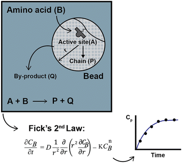
To compare the experimental data obtained by Chen,13–15 Babbrah40 established an explicit model, deriving an expression for Fickian diffusion in spherical geometry, considering a second-order kinetic model, and solving the problem using a finite difference numerical method. The model was derived by drawing a simple but descriptive framework (Fig. 3); a similar approach by Egelhaaf and Rademann is discussed later.21
For the synthesis of polyphenylalaline and polyserine (only for a cross-linking degree of 2%), the model predicts Chen's experimental data reasonably well, though in some cases, the difference between the computed and observed values is significant. Babbrah's model identifies two unknown parameters: the diffusion coefficient and the kinetic constant. In his work, the diffusion coefficient was fixed at 6.0 × 10⁻⁶ cm2 s−1 by fitting the data for the polyserine synthesis at 26 °C and n = 1. Then, the kinetic constant is adjusted for every other experiment to optimize the fit. No boundary condition was established for film diffusion.
In some cases, the inaccuracy of the model may be related to the fixed value of the diffusion coefficient. Optimizing both experimental parameters for every experiment may be more thoughtful. The best k2 values for fitting the model were, in some cases, one order of magnitude lower than those reported by Chen:14 for a cross-linking degree of 2%, a resin loading of 0.7 mmol g−1 and n = 5, using the second-order kinetic model, Chen obtained a value of k2 = 0.34 mol L−1 s−1, while Babbrah reported k2 = 0.05 mol L−1 s−1. This decrease was attributed to intraparticle diffusion, reinforcing the previous hypothesis about a shift in kinetic order.13,15
A significant flaw in Babbrah's modeling approach is the assumption that the concentration of the active sites and amino acid is the same, notwithstanding that the molar ratio was either 1.5 or 1.2 and the model per se predicts a radial concentration profile; in addition, the comparison of the two kinetic models proposed by Chen merged in the diffusional model could be of interest, but this was not performed. A shifting kinetic expression is solved with a diffusion model67 for the hydrogenation of alkenes over Wilkinson's catalyst bound to cross-linked polystyrene beads.
Egelhaaf and Rademann21 proposed a dynamic model derived from Fick's second law for reactions in “spherical compartments”. “Realistic modeling” is expected to be possible only when “simultaneous diffusion and reaction are considered”. Their model is initially derived for the following general chemical reaction with a second-order kinetic expression:
| S + R → P | (4) |
| r = −k2CSCR | (5) |
 | (6) |
 | (7) |
![[thin space (1/6-em)]](https://www.rsc.org/images/entities/char_2009.gif) :
:![[thin space (1/6-em)]](https://www.rsc.org/images/entities/char_2009.gif) 1. In this case ζ = 0.001, indicating that the reaction is the controlling step. If diffusion and activation are important (ζ = 1), the reagent excess still is relevant, reducing the reaction half-time from 20 min (2
1. In this case ζ = 0.001, indicating that the reaction is the controlling step. If diffusion and activation are important (ζ = 1), the reagent excess still is relevant, reducing the reaction half-time from 20 min (2![[thin space (1/6-em)]](https://www.rsc.org/images/entities/char_2009.gif) :
:![[thin space (1/6-em)]](https://www.rsc.org/images/entities/char_2009.gif) 1) to 4 min (10
1) to 4 min (10![[thin space (1/6-em)]](https://www.rsc.org/images/entities/char_2009.gif) :
:![[thin space (1/6-em)]](https://www.rsc.org/images/entities/char_2009.gif) 1). The authors describe this behavior as expected and supported by Fick's first law: the flux should increase directly with the concentration gradient (assuming a constant diffusion coefficient).
1). The authors describe this behavior as expected and supported by Fick's first law: the flux should increase directly with the concentration gradient (assuming a constant diffusion coefficient).
Another factor they analyze is the volume fraction ϕ occupied by the spherical beads in the reaction medium. For ζ = 0.50 and ζ = 0.005, the authors analyzed two cases, ϕ = 0.5 (representative of a close packing, as in a flow reactor) and ϕ = 0.04 (representative of a stirred solution). When both diffusion and the reaction rate are significant (ζ = 0.50), this factor is essential, increasing the time for a 100% conversion from 8 min (ϕ = 0.5) to 22 min (ϕ = 0.04). However, when diffusion is insignificant (ζ = 0.005), the effect of this parameter ϕ is neglectable.
Egelhaaf and Rademann21 modified their model to fit experimental data of Knorr linker attachment on polystyrene resins for modeling enzyme-catalyzed reactions using the Michaelis–Menten kinetic equation and for concentration-dependent diffusion coefficients.
Rademann et al.18 previously investigated the homogeneity of active sites in cross-linked polystyrene by loading it with 5,6-carboxy-tetramethyl-rhodamine (CTMR) and later using confocal fluorescence microscopy. A homogeneous active site distribution opposed previous work by McAlpine and Schreiber.80 The reaction was not diffusion-controlled for the coupling of sodium phenoxide on the Merrifield resin surface. However, when studying the diffusion of rhodamine out of the beads, adsorptive effects were significant in solid phase synthesis, even though “the concept of adsorption is specific for solid–liquid interfaces, not for swelling polymers”. The long time required to remove the last 2% of rhodamine, suggests that these adsorptive effects are particularly interesting for designing washing steps for synthetic protocols.
Groth and collaborators17 studied the diffusion and reaction rates by the acylation of amino-functionalized resins and the staining with chloranil of the unreacted active sites. The model they used to fit their experimental data corresponds to the following equation:
| y = a0(1 − e−kobst) | (8) |
A valuable insight of this study is that the reagent “size” can have a significant impact on the diffusion rate; when comparing the diffusion of acetic anhydride (102 g mol−1) and Fmoc-Phe-OPfp (553 g mol−1), the observed rate constant decreases in one order of magnitude, from 0.51 min−1 to 0.051 min−1. The dependence of the diffusion process on the molecule “size” can be explained through the Smoluchowski–Einstein theory.
Bhayana76 reviews several factors affecting the reaction outcome in SPS by analyzing the reaction between benzylamine and benzyl isocyanate functionalized beads. The importance of parameters such as swelling, bead size, temperature, and loading is discussed. Using the Smoluchowski–Einstein theory, Bhayana states that for reactions in common organic solvents, reactions will be under diffusion control only if they are extremely fast, for a constant rate in the order of 1010 L mol−1 s−1, as it is the case for strong acid–base reactions; in comparison, for solid phase organic synthesis this value ranges from 0.1 to 1.0 L mol−1 s−1, thus, no diffusion control is expected.
Using 1% cross-linked resin beads with sizes of 110 μm, 225 μm, and 530 μm, the reaction mentioned above at 25 °C yielded decreasing values for the rate constant as the particle size increased.76 Bhayana defined the following parameter (an inverse Damköhler number):
 | (9) |
The “true” rate constant (k) and the biomolecular (kb) constant are related by:
 | (10) |
By applying the band broadening theory for a packed bed reactor for SPPS, Scott et al.20 compared the Merrifield resin with resin-coated glass beads. The advantage of using the coated glass beads is that the diffusion length is decreased, and the reaction now takes place only in the resin film covering the beads: “The mass transfer resistance for the coated glass beads is one to two orders of magnitude smaller than that for the Merrifield resin”.20 Using the coated glass beads allowed for a significant cycle time reduction (“ten times faster than the standard Merrifield procedure”20) while maintaining a high yield.
De la Torre et al.82 proposed using refractive index measurement for live monitoring of peptide production at a large scale. While their study lacked kinetic modeling, their data suggest that incorporating mass transfer and kinetics modeling could help improve the synthesis protocol and optimize the reaction time computation. De la Torre et al. also investigated the washing steps after Fmoc deprotection to remove excess piperidine, which is crucial but often overlooked in setting synthetic protocols. The authors found that more washing steps were needed for concentrated Fmoc deprotection solutions. Scott et al.20 also studied washing steps in peptide synthesis.
Several models that theoretically attempt to clarify whether the SPS reaction in gel-like supports is kinetic or diffusion-controlled arrived at different conclusions, possibly due to the many characteristic parameters of each synthetic strategy. A parametric analysis transversal to the different biomolecules is an alternative to address this issue. Defining which systemic (e.g., reagents ratio, molecular size, etc.) and dynamic (chain size) factors are more significant to intraparticle mass transport could result in a more general and simplified model.
6. Conclusions and outlook
We summarize the current understanding regarding momentum, heat, and mass transport in SPS reactors, highlighting the progress and the critical open questions. Throughout the manuscript, we have condensed reference values and descriptive parameters helpful for SPS reactor study and design.Transport and physicochemical processes should be analyzed as critical factors contributing to the solid phase synthesis. Fig. 2 depicts a stepwise description of relevant physicochemical and transport phenomena during the SPS cycle. This analysis lists the phenomena that require deeper study. Though the synthesis of each family of biomolecules follows specific chemical strategies concerning reagents, conditions, etc., the physicochemical aspects are transversal to any solid phase-supported synthesis. Therefore, a general mechanism describing the common steps will be instrumental for process optimations and further development.
SPS advancements have significantly reduced the synthesis time for biopolymers. Back in 1963, Merrifield9 required around 20 hours to produce peptides. Today, flow systems can accomplish this process in just 2 minutes, albeit with a high excess of amino acids.28,43 A deeper understanding of mixing methods and their impact on external mass transfer and kinetic and intraparticle diffusion modeling is crucial for achieving the best balance between cycle time and reagent consumption. This review provides an overview of the current research on these topics for SPS.
An in-depth investigation concerning the implications of the mixing method is urgently needed from an experimental and theoretical point of view to provide the quantitative bases for designing and scaling up SPS reactors. Defining a general approach to estimate the film resistance will be a powerful tool for selecting specific reactor configurations, such as a packed bed or stirred tank, and establishing mixing conditions.
Several reports involving Fickian and kinetic models assess the significance of intraparticle mass transport. However, the results are often contradictory and divergent in order of magnitude. Intraparticle diffusion data, considering factors such as temperature, relevant solvents, and molecular size of the building blocks, are missing tools for process design. The computation of a few experimental parameters, such as reaction constants and diffusion coefficients, could offer an educated guess before synthesis preparation and system design. A parallel assessment of reaction and diffusion is necessary to predict SPS's behavior correctly and decrease reaction times. Egelhaaf and Rademann21 methodology for modeling should be more common practice, but its application is limited due to the lack of proper input data (kinetic models and diffusion coefficients).
In cases like AGA, where a wide temperature range is needed, or SPPS, where the coupling reaction benefits from higher temperature, enhancing the thermal design of synthesis equipment can result in shorter cycle times, reduced energy consumption, and lower costs. For example, the current efficiency of the cooling circuit in AGA is around 10%. Meanwhile, heat transfer in SPS synthesizers is not extensively explored in the literature; the topic is reduced to comparative studies between microwave and conduction as temperature-adjusting methods. Significant aspects of heat transfer are barely mentioned, such as energy and cost optimization, thermal stability in dynamic systems, and systematic understanding of temperature effect on the physicochemical aspects in SPS (reaction kinetics, swelling properties, diffusion coefficient, etc.). Any related improvement to the reactor design appears more like a gadget than the result of a technical analysis; this is an obstacle to independent and continuous improvement.
More specific and thorough research is required for AGA, as the entire available data does not correspond to the characteristic system conditions (solvents, monomer size, related chemistry, etc.). The wide temperature range in AGA makes heat transfer considerations substantial for future process intensification.
Transport phenomena in SPS should not be disregarded. The design and optimization of a reactor for automated SPS, regardless of the target molecule, should start by drawing the physical boundaries that define the reaction environment and the ruling mechanisms for adjusting process conditions.
Author contributions
SPL wrote the original draft, MK reviewed and edited, JDF conceptualized and supervised the work, and PHS administrated the project and resources, supervised the effort, writing – reviewing & editing the manuscript. JDF and PHS share the correspondance authorship. All authors read and agreed with the content of the manuscript.Conflicts of interest
There are no conflicts to declare.Acknowledgements
We gratefully acknowledge financial support from the Max-Planck Society. We are grateful to Dr. Eric Sletten for proofreading the manuscript. Open Access funding provided by the Max Planck Society.Notes and references
- C. M. Runnels, K. A. Lanier, J. K. Williams, J. C. Bowman, A. S. Petrov, N. V. Hud and L. D. Williams, J. Mol. Evol., 2018, 86, 598–610 CrossRef CAS PubMed.
- R. Merrifield, Science, 1965, 150, 178–185 CrossRef CAS PubMed.
- P. H. Seeberger, Acc. Chem. Res., 2015, 48, 1450–1463 CrossRef CAS PubMed.
- G. Lowe and T. Vilaivan, J. Chem. Soc., Perkin Trans. 1, 1997, 555–560 RSC.
- K. Le Mai Hoang, A. Pardo-Vargas, Y. Zhu, Y. Yu, M. Loria, M. Delbianco and P. H. Seeberger, J. Am. Chem. Soc., 2019, 141, 9079–9086 CrossRef CAS PubMed.
- R. K. Singh, J. Sianturi and P. H. Seeberger, Org. Lett., 2022, 24, 2371–2375 CrossRef CAS PubMed.
- K. Sadler and J. P. Tam, Rev. Mol. Biotechnol., 2002, 90, 195–229 CrossRef CAS PubMed.
- L. Christensen, R. Fitzpatrick, B. Gildea, K. H. Petersen, H. F. Hansen, T. Koch, M. Egholm, O. Buchardt, P. E. Nielsen and J. Coull, J. Pept. Sci., 1995, 1, 175–183 CrossRef CAS PubMed.
- R. B. Merrifield, J. Am. Chem. Soc., 1963, 85, 2149–2154 CrossRef CAS.
- M. H. Caruthers, Science, 1985, 230, 281–285 CrossRef CAS PubMed.
- O. J. Plante, E. R. Palmacci and P. H. Seeberger, Science, 2001, 291, 1523–1527 CrossRef CAS.
- B. Merrifield, Br. Polym. J., 1984, 16, 173–178 CrossRef CAS.
- W.-Y. Chen, A kinetic study of solid phase peptide synthesis for the production of polyphenylalanine and polyserine with low excess of the symmetrical anhydride, PhD Thesis, Oklahoma State University, 1988 Search PubMed.
- W.-Y. Chen and G. L. Foutch, Chem. Eng. Sci., 1989, 44, 2760–2762 CrossRef CAS.
- W. Y. Chen and G. L. Foutch, Biotechnol. Prog., 1989, 5, 51–56 CrossRef CAS.
- C. Cheng, F. Micale, J. Vanderhoff and M. El-Aasser, J. Polym. Sci., Part A: Polym. Chem., 1992, 30, 235–244 CrossRef CAS.
- T. Groth, M. Grøtli and M. Meldal, J. Comb. Chem., 2001, 3, 461–468 CrossRef CAS PubMed.
- J. Rademann, M. Barth, R. Brock, H. J. Egelhaaf and G. Jung, Chem. – Eur. J., 2001, 7, 3884–3889 CrossRef CAS PubMed.
- D. Walsh, D. Wu and Y.-T. Chang, Curr. Opin. Chem. Biol., 2003, 7, 353–361 CrossRef CAS PubMed.
- R. Scott, K. K. Chan, P. Kucera and S. Zolty, J. Chromatogr. Sci., 1971, 9, 577–591 CrossRef CAS.
- H.-J. Egelhaaf and J. Rademann, J. Comb. Chem., 2005, 7, 929–941 CrossRef CAS PubMed.
- E. T. Sletten, M. Nuño, D. Guthrie and P. H. Seeberger, Chem. Commun., 2019, 55, 14598–14601 RSC.
- E. T. Sletten, J. Danglad-Flores, M. Nuño, D. Guthrie and P. H. Seeberger, Org. Lett., 2020, 22, 4213–4216 CrossRef CAS PubMed.
- J. Danglad-Flores, S. Leichnitz, E. T. Sletten, A. Abragam Joseph, K. Bienert, K. Le Mai Hoang and P. H. Seeberger, J. Am. Chem. Soc., 2021, 143, 8893–8901 CrossRef CAS PubMed.
- J. N. Naoum, I. Alshanski, G. Mayer, P. Strauss and M. Hurevich, Org. Process Res. Dev., 2022, 26, 129–136 CrossRef CAS.
- I. Alshanski, M. Bentolila, A. Gitlin-Domagalska, D. Zamir, S. Zorsky, S. Joubran, M. Hurevich and C. Gilon, Org. Process Res. Dev., 2018, 22, 1318–1322 CrossRef CAS.
- P. Strauss, F. Nuti, M. Quagliata, A. M. Papini and M. Hurevich, Org. Biomol. Chem., 2023, 21, 1674–1679 RSC.
- A. J. Mijalis, D. A. Thomas III, M. D. Simon, A. Adamo, R. Beaumont, K. F. Jensen and B. L. Pentelute, Nat. Chem. Biol., 2017, 13, 464–466 CrossRef CAS PubMed.
- H. M. Yu, S. T. Chen and K. T. Wang, J. Org. Chem., 1992, 57, 4781–4784 CrossRef CAS.
- H. Paritala, Y. Suzuki and K. S. Carroll, Tetrahedron Lett., 2013, 54, 1869–1872 CrossRef CAS PubMed.
- D. A. Thomas III, A. J. Mijalis, B. L. Pentelute, M. D. Simon and S. Mong, Methods and systems for solid phase, peptide synthesis, US18068838, 2023.
- Y. Bakhatan, D. B. A. Amiel, Y. Sukhran, C. K. Chan, W. C. Lo, P. W. Lu, P. H. Liao, C. C. Wang and M. Hurevich, Chem. Commun., 2022, 58(80), 11256–11259 RSC.
- D. Maclean, J. Baldwin, V. Ivanov, Y. Kato, A. Shaw, P. Schneider and E. Gordon, Pure Appl. Chem., 1999, 71, 2349–2365 CrossRef CAS.
- This definition is almost the exact one presented in the Glossary of Terms Used in Combinatorial Chemistry.
- Y. Yu, A. Kononov, M. Delbianco and P. H. Seeberger, Chem. – Eur. J., 2018, 24, 6075–6078 CrossRef CAS PubMed.
- M. Amblard, J.-A. Fehrentz, J. Martinez and G. Subra, Mol. Biotechnol., 2006, 33, 239–254 CrossRef CAS PubMed.
- E. T. Sletten, J. Danglad-Flores, S. Leichnitz, A. A. Joseph and P. H. Seeberger, Carbohydr. Res., 2022, 511, 108489 CrossRef CAS PubMed.
- G. Fittolani, E. Shanina, M. Guberman, P. H. Seeberger, C. Rademacher and M. Delbianco, Angew. Chem., Int. Ed., 2021, 60, 13302–13309 CrossRef CAS PubMed.
- T. Tyrikos-Ergas, E. T. Sletten, J.-Y. Huang, P. H. Seeberger and M. Delbianco, Chem. Sci., 2022, 13, 2115–2120 RSC.
- G. Babbrah, Master of Science Thesis, Oklahoma State University, 1990 Search PubMed.
- B. Bacsa, K. Horvati, S. Bosze, F. Andreae and C. O. Kappe, J. Org. Chem., 2008, 73, 7532–7542 CrossRef CAS PubMed.
- I. Friligou, E. Papadimitriou, D. Gatos, J. Matsoukas and T. Tselios, Amino Acids, 2011, 40, 1431–1440 CrossRef CAS PubMed.
- N. Hartrampf, A. Saebi, M. Poskus, Z. P. Gates, A. J. Callahan, A. E. Cowfer, S. Hanna, S. Antilla, C. K. Schissel and A. J. Quartararo, Science, 2020, 368, 980–987 CrossRef CAS PubMed.
- I. Zlatev, M. Manoharan, J. J. Vasseur and F. Morvan, Curr. Protoc. Nucleic Acid Chem., 2012, 50, 1.28–21.28 Search PubMed.
- S. A. Scaringe, Methods, 2001, 23, 206–217 CrossRef CAS PubMed.
- M. Grøtli, R. Eritja and B. Sproat, Tetrahedron, 1997, 53, 11317–11346 CrossRef.
- GlycoUniverse, THE GLYCONEER® - Introducing the first commercial, fully automated oligosaccharide synthesizer, https://glycouniverse.com/glyconeer, 2022).
- CEM, Production-scale automated microwave pepdite synthesizer Liberty PRO, https://cem.com/de/liberty-pro?___store=de&___from_store=en.
- CSBio, DNA SYNTHESIZER - HIGH LOAD OLIGO SYNTHESIS, https://www.csbio.com/dna.html).
- AsahiKASEI, Asahi Oligosynthesizer TM: Proven design for mid-scale and large-scale solid phase olygosynthesis https://fluidmgmt.ak-bio.com/products/asahi-oligosynthesizer/).
- Y. Sano, N. Yamaguchi and T. Adachi, J. Chem. Eng. Jpn., 1974, 7, 255–261 CrossRef CAS.
- A. Pandit and J. Joshi, Chem. Eng. Sci., 1983, 38, 1189–1215 CrossRef CAS.
- M. Bouaifi, G. Hebrard, D. Bastoul and M. Roustan, Chem. Eng. Process.: Process Intesif., 2001, 40, 97–111 CrossRef CAS.
- M. Edelstein, P. E. Scott, M. Sherlund, A. L. Hansen and J. L. Hughes, Chem. Eng. Sci., 1986, 41, 617–624 CrossRef CAS.
- N. Stepaniuk, K. Tomazi and M. Stapleton, Reactor and method for solid phase peptide synthesis, US006028172A, 2000.
- W. Li and B. Yan, Tetrahedron Lett., 1997, 38, 6485–6488 CrossRef CAS.
- Y. Bakhatan, I. Alshanski, C.-K. Chan, W.-C. Lo, P.-W. Lu, P.-H. Liao, C.-C. Wang and M. Hurevich, Chem. – Eur. J., 2023, 29(38), e202300897 CrossRef CAS PubMed.
- J. N. Naoum, I. Alshanski, A. Gitlin-Domagalska, M. Bentolila, C. Gilon and M. Hurevich, Org. Process Res. Dev., 2019, 23, 2733–2739 CrossRef CAS.
- F. Gritti and G. Guiochon, J. Chromatogr. A, 2012, 1221, 2–40 CrossRef CAS PubMed.
- S. Coantic, G. Subra and J. Martinez, Int. J. Pept. Res. Ther., 2008, 14, 143–147 CrossRef CAS.
- S. L. Pedersen, A. P. Tofteng, L. Malik and K. J. Jensen, Chem. Soc. Rev., 2012, 41, 1826–1844 RSC.
- Z. P. Gates and N. Hartrampf, Pept. Sci., 2020, 112, e24198 CrossRef CAS.
- L. K. Spare, V. Laude, D. G. Harman, J. R. Aldrich-Wright and C. P. Gordon, React. Chem. Eng., 2018, 3, 875–882 RSC.
- V. J. Inglezakis, M. Balsamo and F. Montagnaro, Ind. Eng. Chem. Res., 2020, 59, 22007–22016 CrossRef CAS.
- N. Frössling, Gerlands Beitr. Geophys., 1938, 52, 170–216 Search PubMed.
- J. Crank, The mathematics of diffusion, Oxford university press, 1979 Search PubMed.
- J. B. Roucis and J. G. Ekerdt, J. Appl. Polym. Sci., 1982, 27, 3841–3849 CrossRef CAS.
- J. B. Roucis and J. G. Ekerdt, J. Catal., 1984, 86, 32–47 CrossRef CAS.
- W. T. Ford, B. J. Ackerson, F. D. Blum, M. Periyasamy and S. Pickup, J. Am. Chem. Soc., 1987, 109, 7276–7280 CrossRef CAS.
- C. Gambs, T. J. Dickerson, S. Mahajan, L. B. Pasternack and K. D. Janda, J. Org. Chem., 2003, 68, 3673–3678 CrossRef CAS PubMed.
- S. Pickup, F. D. Blum, W. T. Ford and M. Periyasamy, J. Am. Chem. Soc., 1986, 108, 3987–3990 CrossRef CAS.
- S. Pickup and F. D. Blum, Macromolecules, 1989, 22, 3961–3968 CrossRef CAS.
- S. Pickup, F. D. Blum and W. T. Ford, J. Polym. Sci., Part A: Polym. Chem., 1990, 28, 931–934 CrossRef CAS.
- Y. Yamane, M. Matsui, H. Kimura, S. Kuroki and I. Ando, J. Appl. Polym. Sci., 2003, 89, 413–421 CrossRef CAS.
- D. Yankov, Enzyme Microb. Technol., 2004, 34, 603–610 CrossRef CAS.
- B. Bhayana, Experimental and theoretical investigations in solid phase reaction kinetics and noncovalent interactions in water, PhD Thesis, University of Pittsburgh, 2007 Search PubMed.
- M. Galizia, D. R. Paul and B. D. Freeman, Polymer, 2016, 102, 281–291 CrossRef CAS.
- J. A. Wesselingh, J. Controlled Release, 1993, 24, 47–60 CrossRef CAS.
- R. Dittmeyer and G. Emig, Handbook of Heterogeneous Catalysis, 2008, DOI:10.1002/9783527610044.hetcat0094.
- S. R. McAlpine and S. L. Schreiber, Chem. – Eur. J., 1999, 5, 3528–3532 CrossRef CAS.
- E. Worch, in Adsorption Technology in Water Treatment, de Gruyter, 2021 Search PubMed.
- B. G. De La Torre, S. Ramkisson, F. Albericio and J. Lopez, Org. Process Res. Dev., 2021, 25, 1047–1053 CrossRef.
| This journal is © The Royal Society of Chemistry 2023 |

