
 Open Access Article
 This Open Access Article is licensed under a
 Creative Commons Attribution 3.0 Unported Licence
Operational parameters relevant to the examination of phosgene synthesis catalysis
Rory
Hughes
 ,
Giovanni E.
Rossi
and
David
Lennon
*
,
Giovanni E.
Rossi
and
David
Lennon
*
School of Chemistry, Joseph Black Building, University of Glasgow, Glasgow, G12 8QQ, UK. E-mail: David.Lennon@glasgow.ac.uk; Tel: +44 (0)141 330 4372
First published on 25th August 2023
Abstract
Large-scale phosgene synthesis, as encountered within isocyanate manufacturing chains, is typically performed by the reaction of carbon monoxide and dichlorine over an activated carbon catalyst. A modified micro-reactor arrangement is described that is used to evaluate the effectiveness of different catalyst formulations. The approach adopted is to utilise diluted gas streams and relatively low operational temperatures (300–500 K); arrangements that afford good temperature control of the exothermic reaction. The article addresses the operational constraints concerning gas handling procedures that ensure avoidance of gas mixtures that fall within explosive limits. A methodology to determine mass balance profiles for the hazardous reaction system is additionally described. Following on from previous studies that exclusively investigated the suitability of a particular activated carbon formulation as a phosgene synthesis catalyst, this study concentrates on Norit RX3 Extra as a generic activated carbon that finds wide application in industrial applications. Mass transport issues are assessed and indicate the reaction system to be operating free from diffusion limitations, enabling kinetic measurements to be undertaken. An activation energy for phosgene synthesis of 43.0 ± 1.1 kJ mol−1 is determined, consistent with the reaction being under chemical control.
1. Introduction
Phosgene (COCl2) is an important reagent in several industrial-scale chemical processes, ranging from polymers to pharmaceuticals to agrichemicals.1 As a feedstock, phosgene is produced on the scale of 12 MT per annum,2 with this figure estimated to increase to 18.6 MT by 2030.3 The vast majority of phosgene production is within the polymer sector, with 95% of global phosgene use in the polyurethane and polycarbonate production chains.3On the Industrial scale, phosgene is synthesised from the reaction of carbon monoxide (CO) and chlorine (Cl2) over an activated carbon catalyst, in an exothermic reaction (ΔH = −107.6 kJ mol−1).4 Although phosgene production is widespread on the industrial scale, it is a relatively under-reported reaction system in the open literature. Two main factors are identified for this paucity of literature for laboratory-based explorations. Firstly, the catalyst is not amenable to study using traditional optical spectroscopic methods, owing to its electronic structure inducing an optical absorption band in the visible region.5 In addition, different formulations of activated carbon, with different surface groups,6 vary in performance, with respect to phosgene synthesis.4 Secondly, the hazardous nature of both the reagents, CO and Cl2, and the product, phosgene,1,7 create a significant barrier to detailed study.
Laboratory-scale studies are, however, valuable at probing the fine details of the intrinsic kinetics and reaction mechanisms of systems.8 There are three main factors to consider when investigating the intrinsic kinetics of a system: maintaining ideal flow conditions, removing temperature gradients, and removing mass transfer gradients.8–10 General rules to follow, as well as diagnostic tests to identify any issues arising from these factors are described elsewhere.8
This publication will focus on a phosgene synthesis apparatus located in the University of Glasgow's Chemical Process Fundamentals Laboratory. The apparatus has previously been used to investigate several aspects of phosgene synthesis over a particular activated carbon formulation, Donau Supersorbon K40.11–14 This includes a proposed reaction mechanism.13 An influential procedure in the elucidation of the mechanism was the realisation of mass balance profiles generated from reaction testing data. These plots revealed a mass imbalance that was primarily attributed to chlorine retention by the catalyst.12 The experimental arrangement has also been used to investigate the oxychlorination of CO to synthesise phosgene over a copper(II)chloride catalyst.15,16
A limitation of the fore-mentioned phosgene synthesis laboratory studies on activated carbon is that they are concentrated on a single grade of activated carbon: Donau Supersorbon K40.11–13 This means that the relevance and transferability of the kinetic and mechanistic studies for phosgene synthesis catalysis in general is unknown currently. Thus, there is a driver to examine other activated carbons and to assess the suitability of the proposed mechanism to other materials that may be applied to large-scale phosgene synthesis. To address this issue, a programme of work has commenced to examine a representative and widely used activated carbon formulation: Norit R3X Extra is selected for this role. Not only is this material widely used in a variety of heterogeneously catalysed reactions17–19 but Mitchell and co-workers have previously demonstrated its efficacy in phosgene synthesis,4 thereby establishing it as a representative phosgene synthesis catalysis. The wider goal of the workplan is to evaluate the generic nature of the proposed reaction mechanism.
As part of that programme, the experimental test apparatus has been up-graded. This article sets out to define the operational parameters connected with analysing phosgene synthesis catalysis. In the first instance it describes the refined experimental apparatus and its associated safety concerns. This is extended to consider the mixing of reagents with respect to explosive mixtures. As the previous work on Donau Supersorbon K40 highlighted the matter of chlorine retention, ‘blank’ measurements using quartz are described to determine the procedural error of mass balance determinations. Experiments performed on Norit R3X Extra to assess mass transfer restrictions and, finally, the activation energy for phosgene synthesis over this generic activated carbon are reported. In this manner, the article determines an operational baseline for the testing of phosgene synthesis catalysts. Dissemination of this collection of information should enable the extent of laboratory testing for this hazardous but commercially relevant reaction system to be more widely employed.
2. Experimental
2.1. Operational platform
The reaction data was produced using the phosgene synthesis apparatus located in the University of Glasgow's Chemical Process Fundamentals Laboratory. Although the apparatus is described in detail elsewhere,11,15 it has been modified and optimised for the current study, as outlined in Fig. 1. Briefly, all reactions were carried out in the gas phase, with gasses connected via 1/8 inch stainless steel tubing, connected by Swagelok fittings. The gasses used in this study were carbon monoxide (BOC, CP grade), chlorine (CK Isotopes, 99.9% purity), phosgene (BOC, 10% in helium) and nitrogen (BOC, 99.998% purity). The flow of the gasses was metred by mass flow controllers (Hastings, CO, N2 COCl2 – HFC-202, Cl2 – HFC-302), which were connected to a control box for remote operation (Chell, CCD104 with Display-X software, via ethernet connection). The incident gas flow rates were as follows: 5 ml min−1 CO, 4 ml min−1 Cl2, 50 ml min−1 N2 pre-reactor and a further 100 ml min−1 N2 post-reactor. This represents a reagent flow of 5.7% of the total flow post-reactor. The partitioning of the nitrogen flow between pre- and post-reactor was chosen to ensure all products remained in the gas phase, while not reducing the residence time of reagents in the reactor excessively. | ||
| Fig. 1 Line diagram of the phosgene synthesis apparatus. | ||
The largest deviation from the previously described apparatus11,15 was the reactor, although bromine and oxygen lines have also been removed. Previously, a 1/2 inch U-shaped quartz reactor was used with the catalyst resting on a glass frit, connected to the gas lines via 1/4 inch Cajon fittings. This reactor was replaced by a 400 mm 1/4 inch straight, quartz reactor, also connected to the gas lines via 1/4 inch Cajon fittings. The catalyst was loaded into this reactor and packed with quartz wool (Elemental Microanalysis). The catalyst used in this investigation was Norit RX3 Extra activated carbon (manufactured by Cabot, purchased from Sigma-Aldrich, reference 901934-500G). The catalyst was, as standard, ground to a size fraction of 250–500 μm using sieves (Endcotts) and a mass of ∼0.1250 g was used for reaction. This corresponds to a gas hourly space velocity (GHSV), under standard flow conditions,20 of 8725 h−1.
This size fraction and mass, however, were varied for some experiments and will be noted as appropriate. Prior to reaction, the catalyst was heated to 373 K for 16 hours to remove any absorbed water. The reactor was housed in a programmable temperature-controlled oven with a maximum operating temperature of 1273 K (Carbolite Gero, TF1 11/32/150, Eurotherm, iTools software, via ethernet connection). In parallel to this reactor, a second bypass rector containing an equal volume of quartz, ground to the same 250–500 μm size fraction, was housed outside the oven. The bypass allowed the flow of the reagents and diluent to be set up in the same flow conditions as the catalyst-containing reactor, with quartz acting as an inert analogue (discussed further in section 3.1). Prior to the reactor a pressure gauge is used to indicate blockages in the apparatus, that could result from slight blockages due to particulate matter, chlorine residues or faulty parts. If any increase in pressure is detected, the line is inspected and/or shut-down to undergo the necessary maintenance procedure.
The product gas stream was analysed by a combination of Fourier transform infrared spectroscopy (IR), ultraviolet/visible spectroscopy (UV/vis) and mass spectrometry (MS) methods. The IR spectrometer (Nicolet Is10) was fitted with a Pyrex gas cell with KBr windows. Spectra were taken over the range of 4000–400 cm−1. The UV/vis spectrometer (Shimadzu UV-1800) was also fitted with a Pyrex gas cell, but with quartz windows. The spectra were taken over the range of 550–190 nm. The mass spectrometer used was a MKS Spectra Microvision Plus RGA. These instruments were operated remotely using Omnic 8 (IR), UV probe (UV/vis) and Process Eye Professional (MS) software. Although used to confirm gas purity, the mass spectrometer was not used for reaction test procedures described herein.
Quantification of the reaction mixture was undertaken as follows. The reagents and product were the only molecules detected in the gas phase which, due to the high dilution methodology adopted, conform to the Beer–Lambert law. Calibration plots of integrated peak areas for CO, COCl2 and Cl2 as a function of flow rate (ml min−1) were constructed that produced well correlated linear plots. IR spectroscopy was used to assess CO and COCl2, UV/vis was used to determine Cl2. Molar volume was used to convert the flow rates to molar flow rates (mmol min−1), so that calibration plots of integrated spectroscopic area (AU) versus molar flow rate (mmol min−1) yielded a straight-line plot that defined a response factor, RF (AU/(mmol min−1)). Thereafter, dividing the observed peak areas by the relevant RF generated the reagent/product flow rate for that sampling point. For phosgene reaction measurements, the flow rates are normalised to catalyst mass, so that the observed rates are presented as mmol min−1 g−1(cat).
| COCl2(g) + 4NaOH(aq) → Na2CO3(aq) + 2NaCl(aq) + 3H2O(l) | (1) |
Any gas which could leak from the system in the case of a fault must be readily detected to ensure safe operation of the apparatus. To this end, there are several detection methods which have been installed around the apparatus and the laboratory. The detectors around the apparatus – inside the fume-hood – allow the fault to be contained and the operator to shut down the reaction without any hazardous material leaving the fume-hood. Detectors outside the fume-hood, on the other hand, indicate whether any fault is contained, which could pose a risk to the operator. Detectors in the fume-hood include phosgene detection tape (Honeywell, Chemcassette), a portable phosgene and chlorine detector (Draeger, X-am 5000 Basic), and a portable carbon monoxide detector (Honeywell, BW Clip). The detection tape can be placed at various vulnerable points around the apparatus and, with a detection limit of 100 ppb, gives a clear visual indication of any leaking of phosgene. Similarly, the portable detectors are placed at the most vulnerable point of the apparatus – the reactor – as it is routinely removed to load and discharge catalyst. The portable detectors give both an audio and visual alarm if any leak should occur. Outside the fume-hood fixed phosgene and carbon monoxide detectors are placed (Crowcon, X-Guard, controlled by Gas Master 2), whilst operatives are equipped with personal phosgene detection badges (Compur). The personal phosgene detection badges are a particularly valuable resource as they indicate a range of different phosgene exposures. Phosgene acute lung injury is characterised by a potentially fatal pulmonary oedema, with a latency period between exposure and oedema.1,24 This latency period can be reliably calculated by multiplying the concentration inhaled by the exposure time.24 As such, the personal phosgene detection badges can be vital for medical professionals to understand the concentration of phosgene inhaled in any potential leak from the system. With all the safety protocols outlined above, operation of the phosgene synthesis apparatus is undertaken in a manner to minimise risk to the operator and the adjacent laboratory environment.
In addition to the chemical risks outlined above, one must not ignore the corrosive potential of chlorine that could compromise the integrity of the apparatus leading to the possibility of a leak of reagents and/or product. Corrosion is facilitated by moisture, therefore, considerable effort is made to ensure the apparatus acts as a closed system with minimal water ingress. Maintaining an anhydrous reaction environment is primarily achieved by maintaining a continuous nitrogen purge throughout the whole apparatus. Importantly, this includes times when the equipment is not being used (12 ml min−1 partitioned as 10 ml min−1 through phosgene regulator and 2 ml min−1 through chlorine regulator). During operation, the fact that the reagent feed-streams are diluted, with nitrogen adopting the role of a carrier gas, further mitigates the corrosion potential of chlorine.
With respect to the parts of the apparatus which are exposed to undiluted chlorine, the regulator is fitted with a purge device to allow for the regulator itself to be purged with nitrogen when not in use. The phosgene connection operates on a similar principle. These arrangements mean that during occasional cylinder changes, the chlorine and phosgene regulators and associated MFCs are retained within a nitrogen atmosphere and experience no exposure to air during the cylinder replacement process. Moreover, to withstand the corrosive atmosphere, the chlorine regulator and mass flow controller are fitted with Kalrez seals. Despite these corrosion resistant seals, the mass flow controller requires servicing on an annual basis to replace the wetted parts to maintain the precision of the device. While not as resistant to corrosion as Kalrez, Viton O-rings are employed on the various Cajon fittings on the apparatus. These O-rings are replaced regularly, not least whenever disconnected, to prevent perishing of the elastomer after exposure to chlorine.
There are some methodologies which can be utilised to reduce the flammability limits of mixtures of gasses. Firstly, a smaller vessel for gasses reduces the flammability limits due to the vessel walls producing a cooling action on the gasses.26 For instance, in a vessel 2 mm in diameter, no combination of carbon monoxide and oxygen are combustible.27 While the 1/8 inch (3.175 mm) stainless steel pipes used in this investigation are larger than this diameter, they do indeed have a significant cooling effect on the gasses. Furthermore, the addition of a diluent gas also reduces the flammability limits of a mixture of gasses.26 Nitrogen, which is being utilised in this investigation as aforementioned, is reported to be the second most effective diluent gas at reducing the flammability limits of four inert gasses tested.28 This was suggested to be the case due to its high specific heat capacity (29.13 J K−1 mol−1),29 compared to other common inert gasses, such as argon or helium (20.97 and 20.87 J K−1 mol−1 respectively).29
With respect to the system of carbon monoxide and chlorine specifically, it has been shown that, despite its oxidative ability, chlorine acts as an extinguisher for a system of carbon monoxide and oxygen.30 Lindeijer determined that in the system of carbon monoxide, chlorine and oxygen at chlorine levels above 15.2%, no mixture of carbon monoxide and oxygen are flammable, as can be seen in the upper line in Fig. 2a. This is in comparison to mixtures of nitrogen, carbon monoxide and oxygen, in which mixtures of carbon monoxide and oxygen are flammable until 71.5% nitrogen, which can be seen in Fig. 2b.30 The extinguishing properties of chlorine in this system can be understood by the method in which chlorine typically oxidises that tends to come from its ability to readily abstract protons but there are no protons to abstract from carbon monoxide. Furthermore, the oxidation of carbon monoxide by chlorine leads to the production of phosgene. This reaction is unable to occur at room temperature without a catalyst or UV radiation,1 although reaction can occur in the absence of catalyst at elevated temperatures.11 However, with the reaction arrangement described in section 2.1, phosgene was only reported to be produced at temperatures above 663 K.11 With respect to carbon monoxide, chlorine acts as an inert gas in terms of flammability under standard operating conditions. Phosgene synthesis is an exothermic process and under industrial conditions peak reaction temperatures can exceed 750 K, which can cause a flammability risk.4 Nevertheless, as outlined in the previous section, the flow of reagents are purposefully dilute and the temperature is relatively low (<400 K), leading to low conversions. This generally low conversion regime reduces the effects of temperature increase in the reactor to insignificant levels, in terms of flammability (the effects of temperature in the reactor will be expanded upon in section 3.2). With respect to both toxicological and flammability hazards, operating under the conditions outlined above, phosgene synthesis can be carried out in a safe and effective manner.
 | ||
| Fig. 2 a) Flammability limits of mixtures of carbon monoxide, chlorine and oxygen. Upper line indicating explosive limits and lower line indicating ignition limits. b) Flammability limits of carbon monoxide, oxygen and nitrogen. Adapted from E. W. Lindeijer, explosion limits of hydrogen and chlorine with oxygen, carbon monoxide and nitrous oxide and of carbon monoxide and oxygen with chlorine and nitrogen, also of carbon monoxide with nitrous oxide, Recl. Trav. Chim. Pays-Bas, 1937 (Online, 2010), 56, 105–118. Copyright Wiley-VCH GmbH. Adapted with permission.30 | ||
2.2. Mass balance considerations
This section describes two procedures: firstly, an isothermal reaction over quartz, secondly, an internal consistency check to estimate the procedural error of the system. In both experiments, the catalyst in the reactor heated by a temperature-controlled oven was replaced by quartz of an equal volume (0.41 cm3, 0.4410 g), ground to 250–500 μm. In the isothermal experiment, the flow of gasses was operated at the standard flow rate, as previously described (see section 2.1). As such, the flow rates and regimes of gasses matched those that would be found if the reactor contained catalyst. Ground quartz of the same size and volume as the heated reactor was placed in a separate, unheated by-pass reactor. The gas flows were set up for 1 hour over the bypass before initial A0 measurements were taken. Once the A0 measurement was taken, the flow was passed over the heated reactor at 323 K, and measurements were taken every 20 minutes for 300 minutes, including 0 minutes. Each measurement was taken 4 times in series with the average and standard deviation determined.For the procedural error check, the flow of gasses was varied across 5 different samples, as shown in Table 1. All flow rates totalled the standard 159 ml min−1 for spectroscopic analysis, with COCl2 being used as a 10% COCl2 in helium, accounting for the flow rate discrepancy. The flow of gasses was allowed to be set up for 60 minutes before spectra were taken.
| Sample number | CO flow rate (mmol min−1) | Cl2 flow rate (mmol min−1) | COCl2 flow rate (mmol min−1) | N2 flow rate (ml min−1) |
|---|---|---|---|---|
| 1 | 0.2454 | 0.1636 | 0.0409 | 139 |
| 2 | 0.2045 | 0.2045 | 0.0818 | 129 |
| 3 | 0.2454 | 0.1227 | 0.1227 | 120 |
| 4 | 0.2045 | 0.1227 | 0.1636 | 111 |
| 5 | 0.1227 | 0.2045 | 0.1227 | 121 |
2.3. Mass transfer limitation considerations
To diagnose the potential for concentration gradients affecting the reaction performance, 3 tests were performed – one for intra-phase mass transfer and a second for inter-phase mass transfer, as suggested by Perego and Peratello.8 A third test was performed to calculate the apparent activation energy of the reaction. To measure intra-phase diffusion limitations, the catalyst size fraction was modified, while the flow of gas was maintained at standard conditions.8 The size fractions selected were 150–212, 212–250, 250–500, 500–600 and 600–700 μm, as well as extrudate pellets (as-supplied, diameter: 1.8 mm, length: 2.5–5 mm). The pellets were packed fore and aft with additional ground quartz (250–500 μm) to minimise the possibility of gas by-pass.To measure inter-phase diffusion limitations, the mass of the catalyst and flow rate were modified while maintaining the overall GHSV of 8725 h−1.8,31,32 Masses and flow rates were varied, as described in Table 2.
| N2 flow rate pre-reactor (ml min−1) | N2 flow rate post-reactor (ml min−1) | Catalyst mass (g) |
|---|---|---|
| 30 | 120 | 0.0826 |
| 50 | 100 | 0.1250 |
| 60 | 90 | 0.1462 |
| 70 | 80 | 0.1674 |
| 80 | 70 | 0.1886 |
All size fractions were ground and separated using sieves (Endcotts) and heated to 373 K for 16 hours before reaction to remove water. Flow rates of gasses were set up over the bypass containing an equal volume of quartz ground to 250–500 μm for 1 hour, before flows were passed over the catalyst. Each size fraction and catalyst mass was placed under reaction conditions for 240 minutes with samples taken at 4 intervals: 120, 180, 210 and 240 minutes. Each sample consisted of 4 spectra, with the peak area under investigation being averaged. The standard deviation of the 4 time interval samples was used to estimate experimental error.
To calculate the apparent activation energy of the reaction, a procedure was adopted that utilised standard flow rate and catalyst parameters (see section 2.1) over 0.1250 g of Norit RX3 Extra activated carbon catalyst. The temperature of reaction was varied by ∼5 K per sample and a total of 5 samples were taken. The temperatures selected were 310, 316, 322, 328 and 333 K. As previously, the catalyst was heated to 373 K for 16 hours before reaction to remove any absorbed water. Flows of gasses were set up over a bypass containing ground quartz (0.4410 g, 250–500 μm) for 1 hour before being passed over the catalyst. The reactor was left at a given temperature for 1 hour before samples were taken and the temperature increased. Each sample consisted of 4 spectra taken in succession and then the area of the peaks of the 4 spectra was used to calculate the average and standard deviation.
3. Results and discussion
3.1. Reaction over quartz
Fig. 3 and 4 present a selection of IR and UV/vis spectra collected under these conditions. Inspecting Fig. 3 reveals features around 2140 cm−1, which are caused by the rotational motion of CO.11 The features around 2350 and 670 cm−1 are related to atmospheric CO2 (ref. 35) present in the IR spectrometer and are not believed to be part of the reaction system. The intensity of the CO peak does not notably change in intensity over the course of the 300 minutes on stream. Furthermore, phosgene produces two highly intense features at around 1825 and 845 cm−1,1 neither of which are present in the spectra. This indicates that there is no reaction taking place between CO and Cl2 over quartz at 323 K. Inspection of Fig. 4 allows a similar conclusion to be drawn; only one feature at 330 nm is visible in the UV/vis spectra presented and that corresponds to Cl2.11 Some deviation in the intensity of these peaks is present over the course of 300 minutes, however, this does not appear to be systematic. Furthermore, there is no presence of any peaks at 230 nm, which could be attributed to phosgene,11 again, indicative that no reaction is taking place over quartz.
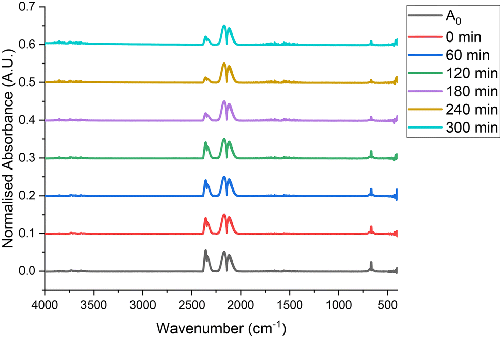 | ||
| Fig. 3 Infrared spectra of CO and Cl2 passed over 0.4410 g of quartz, ground to 250–500 μm, with respective flow rates of 5 ml min−1 and 4 ml min−1 in a 150 ml min−1 flow of N2 (50 ml min−1 pre-reactor, 100 ml min−1 post-reactor) at 323 K over a timescale of 300 min, with A0 corresponding to a bypass reactor, also containing ground quartz at 293 K. | ||
 | ||
| Fig. 4 Ultraviolet/visible spectra of CO and Cl2 passed over 0.4410 g of quartz, ground to 250–500 μm, with respective flow rates of 5 ml min−1 and 4 ml min−1 in a 150 ml min−1 flow of N2 (50 ml min−1 pre-reactor, 100 ml min−1 post-reactor) at 323 K over a timescale of 300 min, with A0 corresponding to a bypass reactor, also containing ground quartz at 293 K. | ||
Quantification of the data shown in Fig. 3 and 4 is presented in Fig. 5 and 6 which, respectively, display a reaction profile and mass balance as a function of time on stream. Fig. 5 reveals that, other than slight fluctuations, the flow rate of CO and Cl2 remains constant throughout the 300 min time on stream, indicating that no reagents are consumed at 323 K. The standard deviation of values across the range of 12 samples is 7.6 × 10⁻⁴ and 6.0 × 10⁻⁴ mmol min−1 for CO and Cl2 respectively. Furthermore, no phosgene nor any other product is formed. Fig. 6 suggests very slight mass loss at 180, 210 and 300 minutes. However, this mass loss is of the order of 0.2% of the total flow exiting the reactor. As such, it is suggested that this is a result of fluctuations in the gas flow, rather than reagents being used in a reaction. As a result of the data presented in Fig. 3–6, it is suggested that, at 323 K and over a timescale of 300 min, ground quartz acts as a suitable inert analogue for the catalyst. Moreover, there is no contribution from a homogeneous reaction. These measurements present a useful baseline for inspection of activated carbon to effect phosgene synthesis.
 | ||
| Fig. 5 A reaction profile of gasses exiting the reactor when CO and Cl2 are passed over 0.4410 g of quartz, ground to 250–500 μm, with respective flow rates of 5 ml min−1 and 4 ml min−1 in a 150 ml min−1 flow of N2 (50 ml min−1 pre-reactor, 100 ml min−1 post-reactor) at 323 K over a timescale of 300 min, with the plot a −20 (A0) corresponding to a bypass reactor, also containing ground quartz at 293 K. | ||
 | ||
| Fig. 6 A mass balance of gasses exiting the reactor when CO and Cl2 are passed over 0.4410 g of quartz, ground to 250–500 μm, with respective flow rates of 5 ml min−1 and 4 ml min−1 in a 150 ml min−1 flow of N2 (50 ml min−1 pre-reactor, 100 ml min−1 post-reactor) at 323 K over a timescale of 300 min, with A0 corresponding to a bypass reactor, also containing ground quartz at 293 K. | ||
 | ||
| Fig. 7 A mass balance of gasses exiting the reactor when CO, Cl2 and COCl2 are passed over 0.4410 g of quartz, ground to 250–500 μm, with the total flow rate of gasses equalling 159 ml min−1 at 293 K. With sample 1 corresponding to flows of CO, 6 ml min−1, Cl2, 4 ml min−1, COCl2 1 ml min−1, sample 2, CO 5 ml min−1, Cl2 5 ml min−1, COCl2 2 ml min−1, sample 3, CO, 6 ml min−1, Cl2, 3 ml min−1, COCl2, 3 ml min−1, sample 4, CO, 5 ml min−1, Cl2 3 ml min−1, COCl2 4 ml min−1 and sample 5, CO, 3 ml min−1, Cl2 5 ml min−1, COCl2 3 ml min−1. The red dashed line represents 100% of calculated molar flow rate. | ||
| Sample 1 | Sample 2 | Sample 3 | Sample 4 | Sample 5 | |
|---|---|---|---|---|---|
| Total flow of CO, Cl2 and COCl2 (%) | 99.54 | 102.70 | 98.58 | 100.52 | 105.45 |
3.2. Diffusion gradient considerations
For data generated in the study of a catalyst to be intrinsic kinetic data, one must ensure that the reagent/catalyst mixing is ideal and that there is no temperature or concentration gradients in the system. As a general rule, to ensure plug flow conditions in the gas–solid system as described in section 2.1, the bed length should be at least 50 particles in diameter and the height at least 10.8,9 The mass and density of the catalyst (0.1250 g and 0.308 g cm−3) in conjunction with the reactor design and size fraction of 250–500 μm corresponds to an approximate bed length of 30 mm and internal diameter of 5 mm. For the aforementioned reactor parameters, the bed length is between 60 and 120 particles, and the internal diameter is between 10 and 20 particles. As such, in terms of both bed length and height, it can be assumed that plug flow conditions are met by this reactor configuration.Temperature gradients are an important factor to consider in an exothermic reaction such as phosgene synthesis (ΔH = −107.6 kJ mol−1).4 Two common techniques used to counteract temperature gradients are decreasing the catalyst bed height and introducing a diluent gas to the feed stream. As previously mentioned, any further reduction in the diameter of the reactor could prevent ideal mixing in the system due to the small quantity of catalyst used in this arrangement. This additionally prevents hotspots from forming in the catalyst bed. It is suggested that the excess flow of nitrogen as a carrier gas, with reagent flow being 15.25% of total flow through the reactor, also prevents temperature gradients forming in the catalyst bed, as discussed in section 2.1.2. As a result, when an external thermocouple (Type K, RS Pro, 1316, 0.1 °C resolution) was connected to the exterior of the reactor containing the catalyst bed, it detected no temperature gradient. Whereas it is acknowledged that this test is unable to probe the internal temperature of the bed, the inclusion of a thermocouple within the reactor was not attempted due to concerns of the thermocouple experiencing corrosion issues. Future designs of reactor will include the provision of a thermocouple pocket. Dilution of the catalyst bed was not attempted during this work but dilution with a material such as ground quartz will be attempted for future measurements. Despite these caveats, it is assumed that the catalyst is free from temperature gradients in the set-up described.
An additional factor for consideration regarding intrinsic kinetics is mass transfer limitations.8,10 Perego and Peratello describe tests that assess if a plug flow reactor with a gas–solid interface is absent of both intra-phase (internal) and inter-phase (external) concentration gradients. As such, mass transfer limitations will be assessed in the upcoming sections in accordance with these tests.
 | ||
| Fig. 8 Phosgene formation as a function of Norit RX3 Extra size fraction at 323 K, with gas flow rates corresponding to CO, 5 ml min−1, Cl2, 4 ml min−1, N2 pre-reactor, 50 ml min−1, post-reactor, 100 ml min−1, each sample corresponds to 240 min ToS. The error bars represent the standard deviation of the 4-time intervals sampled at 120, 180, 210 and 240 minutes. The red dashed line represents phosgene formation rate as a function of as-received extrudate catalyst. | ||
A further test was performed with as-received extrudate catalyst pellets. The reactor was loaded with five catalyst pellets and packed with ground quartz (250–500 μm) to minimise bypassing effects. The full pellet measurement is denoted in Fig. 8 by the red dashed line. Comparison between the ground and as-received catalyst allows the catalyst effectiveness factor, η, to be calculated. The catalyst effectiveness factor is related to the Thiele modulus of the pore, ϕ; a measure of physical and geometric properties of the catalyst, namely effective diffusivity, pellet density and pore length.8,36 As such, the catalyst effectiveness factor can be used as a proxy to estimate the degree of intra-phase diffusion limitations for the pellet.4 The effectiveness factor can be calculated from the ratio of phosgene formation over the as-received pellet versus the ground catalyst,4 and reveals a value of 0.67. Mitchell and co-workers reported a catalyst effectiveness factor of 0.89 for Norit RX3 Extra.4 It is possible that the lower value reported here reflects a degree of reagent by-pass with the pellets. Nevertheless, an effectiveness factor of < unity indicates that intra-phase mass transfer affects the catalyst pellets to a significant degree. Moreover, for the reactor configuration described in section 2.1, the selected size fraction of 250–500 μm of catalyst is free of intra-phase mass transfer.
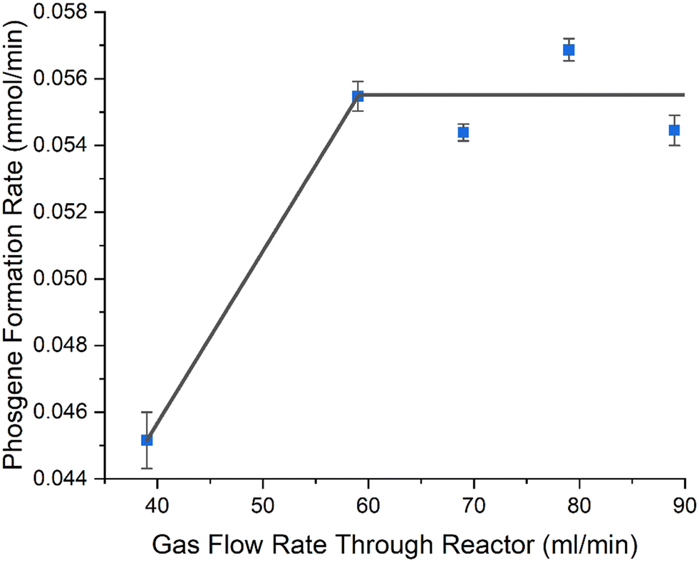 | ||
| Fig. 9 Phosgene formation rate as a function of gas flow rate over Norit RX3 Extra, while altering catalyst mass to maintain a gas hourly space velocity of 8725 h−1. Catalyst was ground to 250–500 μm and gas flow rates of CO, 5 ml min−1, Cl2, 4 ml min−1, with N2 flow rates being partitioned between pre-reactor and post-reactor as follows 30/120, 50/100, 60/90, 70/80, 80/70 ml min−1, maintaining a total flow rate of 159 ml min−1 post reactor. Each sample corresponds to 240 min ToS. The error bars represent the standard deviation of the 4-time intervals sampled at 120, 180, 210 and 240 minutes. Grey line represents a ‘guide for the eye’. | ||
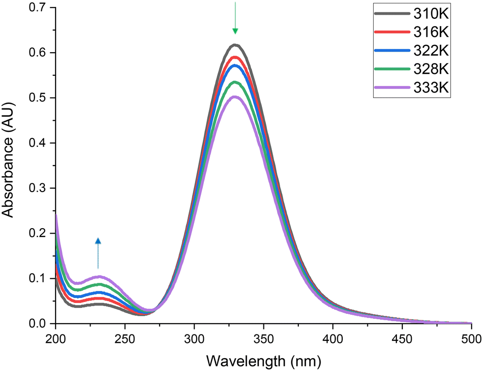
 , 1011 (ν2 + ν5) and the C–Cl symmetric stretch (ν2) at 576 cm−1.1,11 As discussed in section 3.1.1, signals are visible at 2350 and 670 cm−1, which are attributable to atmospheric CO2 in the path length of the infrared beam, which are not believed to be part of the reaction system.35Fig. 11 shows that as a function of temperature, the feature associated with Cl2, at 330 nm,11 decreases (green arrow). This indicates that chlorine is being progressively consumed as a function of temperature. Furthermore, the feature associated with phosgene, at 230 nm,11 increases (blue arrow), indicating that phosgene is being progressively produced as a function of temperature. Quantification of Fig. 10 and 11 allow determination of the consumption of reagents. For reference, reaction conversion, as signified by CO consumption at 322 K corresponds to 17.1%.
 | ||
| Fig. 10 Infrared spectra of CO and Cl2 passed over 0.1250 g of Norit RX3 Extra activated carbon catalyst, ground to 250–500 μm, with respective flow rates of 5 ml min−1 and 4 ml min−1 in a 150 ml min−1 flow of N2 (50 ml min−1 pre-reactor, 100 ml min−1 post-reactor) over a temperature range of 310–333 K. | ||
 | ||
| Fig. 11 Ultraviolet/visible spectra of CO and Cl2 passed over 0.1250 g of Norit RX3 Extra activated carbon catalyst, ground to 250–500 μm, with respective flow rates of 5 ml min−1 and 4 ml min−1 in a 150 ml min−1 flow of N2 (50 ml min−1 pre-reactor, 100 ml min−1 post-reactor) over a temperature range of 310–333 K. | ||
It is worthwhile noting that over this temperature range the only identifiable product in Fig. 10 and 11 is phosgene. No by-products are observed, indicating the reaction to be totally selective under the conditions studied. Crucially, no carbon tetrachloride (CCl4) is detected in the gas phase emissions from the reactor. In the industrial operation, CCl4 is commonly observed, where it is thought to arise from oxidation of the activated carbon by the chlorine reagent.4,37 However, large-scale phosgene production typically involves concentrated reagent feed-streams and reaction temperatures considerably higher than those encountered here. Indeed, temperatures in excess of 723 K can be encountered in the industrial operation4 IR spectroscopy is particularly sensitive to the presence of CCl4, with the intense ν1 C–Cl stretch at ∼780 cm−1 (ref. 38) being highly diagnostic of the moiety. Fig. 10 shows no peak to be observable at this energy, confirming its absence in these measurements.
Fig. 12 presents an Arrhenius plot of the natural logarithm of the phosgene formation rate (ln[COCl2]) versus 1/T that yields a highly corelated linear slope (R2 = 0.99) and an apparent activation energy of 43.0 ± 1.1 kJ mol−1. This activation energy, in conjunction with the findings from section 3.2.2, indicates the reaction to be operating in the absence of inter-phase mass transfer limitations.8
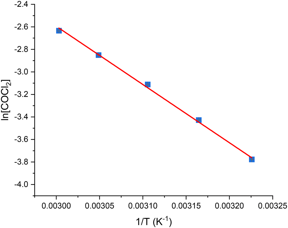 | ||
| Fig. 12 Arrhenius plot of the natural logarithm of the COCl2 formation rate when CO and Cl2 are passed over 0.1250 g of Norit RX3 Extra activated carbon catalyst, ground to 250–500 μm, with respective flow rates of 5 ml min−1 and 4 ml min−1 in a 150 ml min−1 flow of N2 (50 ml min−1 pre-reactor, 100 ml min−1 post-reactor) over a temperature range of 310-333 K after 60 min ToS. | ||
The activation energy calculated here also correlates with other values calculated for phosgene synthesis over activated carbons: Donau Supersorbon K40 (34.1 kJ mol−1 (ref. 12)); Bayer AKT-4 (36.0 kJ mol−1);39 C60 fullerene (56 kJ mol−1 (ref. 40)). Furthermore, Mitchell and co-workers calculated activation energies for 7 different activated carbons and found a range of 42–50 kJ mol−1,4 with one of the samples being Norit RX3 Extra.
4. Conclusions
An experimental apparatus was commissioned and used for the examination of phosgene synthesis over a specific activated carbon (Donau Supersorbon K40).11–14 This communication outlines recently adopted refinements to that facility. A range of toxicological and flammability hazard reduction methodologies relevant to the operation of the new facility are additionally described. The suitability of ground quartz as an inert analogue to activated carbon is confirmed and enables the accuracy of mass balance profiles to be determined. Measurements of a generic activated carbon (Norit RX3 Extra) indicate the absence of intra- or interphase mass transfer limitations with this reaction system. Consistent with these findings, an apparent activation energy for phosgene synthesis of 43.0 ± 1.1 kJ mol−1 is determined over a temperature range of 310–333 K. Collectively, these arrangements describe an operational platform for the testing of phosgene synthesis catalysts. Future work will adopt these protocols to further examine Norit RX3 Extra, to assess whether the previously proposed reaction mechanism is generic and applicable to activated carbons other than Donau Supersorbon K40.Data management statement
Data for this paper, including spectroscopic datasets, are available at the University of Glasgow Library [DOI: https://doi.org/10.5525/gla.researchdata.1489].Conflicts of interest
There are no conflicts of interest to declare.Acknowledgements
The EPSRC are thanked for the provision of a Ph.D. studentship (RH, EP/R513222/1 and EP/T517896/1).References
- T. A. Ryan, C. Ryan, E. A. Seddon and K. R. Seddon, Phosgene and Related Carbonyl Halides, Elseiver, Amsterdam, 1996 Search PubMed.
- P. Voßnacker, A. Wüst, T. Keilhack, C. Müller, S. Steinhauer, H. Beckers, S. Yogendra, Y. Schiesser, R. Weber, M. Reimann, R. Müller, M. Kaupp and S. Riedel, Sci. Adv., 2021, 7, 40 CrossRef PubMed.
- L. Cotarca, C. Lange, K. Meurer and J. Pauluhn, in Ullmann's Encyclopedia of Industrial Chemistry, Wiley-VCH Verlag GmbH & Co. KGaA, Weinheim, Germany, 2019, pp. 1–30 Search PubMed.
- C. J. Mitchell, W. van der Borden, K. van der Velde, M. Smit, R. Scheringa, K. Ahrika and D. H. Jones, Catal. Sci. Technol., 2012, 2, 2109 RSC.
- E. Fuente, J. A. Menéndez, M. A. Díez, D. Suárez and M. A. Montes-Morán, J. Phys. Chem. B, 2003, 107, 6350–6359 CrossRef CAS.
- M. S. Shafeeyan, W. M. A. W. Daud, A. Houshmand and A. Shamiri, J. Anal. Appl. Pyrolysis, 2010, 89, 143–151 CrossRef CAS.
- L. Cotarca and H. Ekert, Phosgenations – A Handbook, Wiley VCH, Weinheim, 2006 Search PubMed.
- C. Perego and S. Peratello, Catal. Today, 1999, 52, 133–145 CrossRef CAS.
- J. R. Anderson and K. C. Pratt, Introduction to Characterization and Testing of Catalysts, Academic Press, North Ryde, 1st edn, 1985 Search PubMed.
- C. N. Satterfield, Heterogeneous Catalysis in Industrial Practice, Krieger Publishing Company, Malabar, 2nd edn, 1991 Search PubMed.
- G. E. Rossi, J. M. Winfield, C. J. Mitchell, W. van der Borden, K. van der Velde, R. H. Carr and D. Lennon, Appl. Catal., A, 2020, 594, 117467 CrossRef CAS.
- G. E. Rossi, J. M. Winfield, C. J. Mitchell, N. Meyer, D. H. Jones, R. H. Carr and D. Lennon, Appl. Catal., A, 2020, 602, 117688 CrossRef CAS.
- G. E. Rossi, J. M. Winfield, N. Meyer, D. H. Jones, R. H. Carr and D. Lennon, Appl. Catal., A, 2021, 609, 117900 CrossRef CAS.
- G. E. Rossi, J. M. Winfield, N. Meyer, D. H. Jones, R. H. Carr and D. Lennon, Ind. Eng. Chem. Res., 2021, 60, 3363–3373 CrossRef CAS PubMed.
- S. Guan, P. R. Davies, E. K. Gibson, D. Lennon, G. E. Rossi, J. M. Winfield, J. Callison, P. P. Wells and D. J. Willock, Faraday Discuss., 2018, 208, 67–85 RSC.
- S. Guan, G. E. Rossi, J. M. Winfield, C. Wilson, D. MacLaren, D. J. Morgan, P. R. Davies, D. J. Willock and D. Lennon, Faraday Discuss., 2021, 229, 318–340 RSC.
- F. Duarte, F. J. Maldonado-Hódar and L. M. Madeira, Appl. Catal., B, 2011, 103, 109–115 CrossRef CAS.
- A. Malaika and M. Kozłowski, Int. J. Hydrogen Energy, 2010, 35, 10302–10310 CrossRef CAS.
- J. M. Solar, F. J. Derbyshire, V. H. J. de Beer and L. R. Radovic, J. Catal., 1991, 129, 330–342 CrossRef CAS.
- P. L. Christensen, J. Nielsen and T. Kann, J. Clin. Monit., 1992, 8, 279–284 CrossRef CAS PubMed.
- J. V. Davies and H. O. Pritchard, J. Chem. Thermodyn., 1972, 4, 23–29 CrossRef CAS.
- M. B. Hocking, in Modern Chemical Technology and Emission Control, Springer Berlin Heidelberg, Berlin, Heidelberg, 1985, pp. 134–154 Search PubMed.
- S. Kumar, V. Drozd and S. Saxena, Catalysts, 2012, 2, 532–543 CrossRef CAS.
- J. Pauluhn, Toxicology, 2021, 450, 152682 CrossRef CAS PubMed.
- K.-D. Henning and H. von Kienle, in Ullmann's Encyclopedia of Industrial Chemistry, Wiley-VCH Verlag GmbH & Co. KGaA, Weinheim, Germany, 2010 Search PubMed.
- H. F. Coward and G. W. Jones, Limits of flammability of gases and vapors (No. 503-508), US Government Printing Office, Wahington DC, 1952 Search PubMed.
- H. le Chatelier and O. Boudouard, Process Saf. Prog., 2005, 24, 3–5 CrossRef.
- H. F. Coward and F. J. Hartwell, J. Chem. Soc., 1926, 129, 1522–1532 RSC.
- P. Atkins and J. de Paula, Atkins' Physical Chemistry, Oxford University Press, Oxford, 10th edn, 2014 Search PubMed.
- E. W. Lindeijer, Recl. Trav. Chim. Pays-Bas, 2010, 56, 105–118 CrossRef.
- F. Trejo and J. Ancheyta, Catal. Today, 2005, 109, 99–103 CrossRef CAS.
- J. Ancheyta, G. Marroquín, M. J. Angeles, M. J. Macías, I. Pitault, M. Forissier and R. D. Morales, Energy Fuels, 2002, 16, 1059–1067 CrossRef CAS.
- M. A. G. Hevia, A. P. Amrute, T. Schmidt and J. Pérez-Ramírez, J. Catal., 2010, 276, 141–151 CrossRef CAS.
- P. V. Snytnikov, V. A. Sobyanin, V. D. Belyaev, P. G. Tsyrulnikov, N. B. Shitova and D. A. Shlyapin, Appl. Catal., A, 2003, 239, 149–156 CrossRef CAS.
- A. M. Ricks, A. D. Brathwaite and M. A. Duncan, J. Phys. Chem. A, 2013, 117, 11490–11498 CrossRef CAS PubMed.
- C. H. Bartholomew and R. J. Farrauto, Fundamentals of Industrial Catalytic Processes, John Wiley & Sons, New Jersey, 2nd edn, 2006 Search PubMed.
- L. Abrams, W. V. Cicha, L. E. Manzer and S. Subramoney, Stud. Surf. Sci. Catal., 2000, 130, 455–460 CrossRef.
- G. Herzberg, Molecular Spectra and Molecular Structure Volume II Infrared and Raman Spectra of Polyatomic Molecules, Krieger Publishing Company, Malabar, 2nd edn, 1991, vol. 2 Search PubMed.
- E. N. Shapatina, V. L. Kuchaev, B. E. Pen'kovol and M. I. Temkin, Kinet. Katal., 1974, 17, 644–652 Search PubMed.
- N. K. Gupta, A. Pashigreva, E. A. Pidko, E. J. M. Hensen, L. Mleczko, S. Roggan, E. E. Ember and J. A. Lercher, Angew. Chem., Int. Ed., 2016, 55, 1728–1732 CrossRef CAS.
| This journal is © The Royal Society of Chemistry 2023 |