
 Open Access Article
 This Open Access Article is licensed under a Creative Commons Attribution-Non Commercial 3.0 Unported Licence
A combined experimental and multiscale modeling approach for the investigation of lab-scale fluidized bed reactors†
Riccardo
Uglietti‡
 ab,
Daniele
Micale‡
a,
Damiano
La Zara
b,
Aristeidis
Goulas
b,
Luca
Nardi
a,
Mauro
Bracconi
a,
J. Ruud
van Ommen
*b and
Matteo
Maestri
*a
ab,
Daniele
Micale‡
a,
Damiano
La Zara
b,
Aristeidis
Goulas
b,
Luca
Nardi
a,
Mauro
Bracconi
a,
J. Ruud
van Ommen
*b and
Matteo
Maestri
*a
aLaboratory of Catalysis and Catalytic Processes, Dipartimento di Energia, Politecnico di Milano, via La Masa 34, 20156 Milano, Italy. E-mail: matteo.maestri@polimi.it
bDepartment of Chemical Engineering, Delft University of Technology, Van der Maasweg 9, 2629 HZ Delft, The Netherlands. E-mail: J.R.vanOmmen@tudelft.nl
First published on 5th May 2023
Abstract
We show the potential of coupling numerical and experimental approaches in the fundamental understanding of catalytic reactors, and in particular fluidized beds. The applicability of the method was demonstrated in a lab-scale fluidized bed reactor for the platinum-based catalytic oxidation of hydrogen. An experimental campaign has been carried out for synthesizing the catalyst powders by means of atomic layer deposition in a fluidized bed reactor and characterizing them. Catalytic testing has been also run to collect data both in fixed and fluidized bed configurations. Then, after the validation of the in-house first-principles multiscale Computational Fluid Dynamic – Discrete Element Method (CFD–DEM) model, the fundamental understanding which can be achieved by means of detailed numerical approaches is reported. Thus, the developed framework, coupled with experimental information, results in an optimal design and scale-up procedure for reactor configurations promising for the energy transition.
Introduction
Fluidization technology is deemed to play a crucial role in the quest for more efficient and environmentally sustainable chemical processes. In particular, fluidized bed reactors are receiving large interest due to their highly homogeneous reaction environment resulting in a promising reactor configuration for fostering the energy transition.These properties are provided by the complex fluid dynamics behaviour, related to the movement of the solid phase, which has a strong influence on gas–solid interaction and hence, on the conversion and selectivity of catalytic reactions.1,2 On the one hand, the multiphase flow induces a mixing which affects the species contact time. On the other hand, the formation of fluid dynamic structures (e.g. bubbles, particle clusters) can introduce additional transport resistances which decrease the catalyst utilization.
In this context, the numerical models are not always capable to catch the aforementioned complexities, hindering the accurate description of fluidized systems specially in non-conventional reactor geometries which can be adopted to develop novel sustainable processes. Hence, the fundamental understanding of these reactor units requires advanced computational approaches, such as the detailed multiscale modeling.3–6 According to this approach, the first-principles descriptions of the phenomena occurring in the reaction environment are coupled in a unique framework, which allows for the understanding of their interplay and the fundamental analysis of the desired system.
This modeling approach has provided interesting insights in the context of fixed bed and structured reactors.7–12 However, literature investigations of fluidized bed reactors for several catalytic processes (e.g. ozone decomposition,13 biomass gasification,14,15 methanation,16 methanol to olefins17) do not usually use first-principles multiscale modeling. These computational approaches neglect the description of phenomena that could occur inside the reactive environment. Indeed, in these works the surface chemistry is solved without accounting for the mass transport resistances, which can strongly affect the outcomes of the process.18 Consequently, Maestri and co-workers19 extended the multiscale modeling to fluidized systems by coupling the Computational Fluid Dynamic – Discrete Element Method (CFD–DEM) model of the gas–solid flow20–22 with the description of the physico-chemical phenomena involved in the fluidized systems (i.e. gas–solid species/heat transport and catalytic reactions via detailed microkinetic models).23 This approach has been applied to accurately reproduce the behaviour of systems operated in chemical regime,19 and it has been additionally combined with speed-up methodologies to significantly reduce the computational cost associated with the solution of the detailed catalytic kinetics,24 enabling the analysis of million particle fluidized reactors.24,25 In this work, we show the potential of combining computational multiscale modeling with information obtained through experimental campaigns to investigate complex systems, such as catalytic fluidized bed reactors. In particular, we have analysed a lab-scale fluidized bed in which hydrogen oxidation takes place over a platinum on alumina supported catalyst.
During the experimental campaign, we have synthesized the Pt catalyst by means of atomic layer deposition (ALD) in a fluidized bed reactor,26,27 starting from alumina Geldart B powder.28 Catalytic particles with two different Pt loadings (1 and 2.3% w/w) have been synthetized and subsequently mechanically and chemically characterized to quantify all the properties needed to properly simulate the system by means of the multiscale CFD–DEM framework. We then operated the reactor unit in fixed bed configuration in order to collect the data needed to derive a kinetic expression at the selected operating conditions (i.e. ambient temperature and with oxygen as the limiting reactant). Finally, we performed the experimental testing in the fluidized bed reactor configuration for both the two different Pt loadings and analysed the outlet species composition at different inlet gas velocities.
The corresponding operating conditions have been also simulated with the multiscale CFD–DEM, properly configured by means of all the experimentally derived properties, to show the reliability of the approach not only in chemical regime but also in case of an important contribution of the mass transport resistances. To do so, the comparison of the performances, in terms of oxygen conversions at the outlet of the reactor, between the experimental data and the multiscale one has been carried out by achieving an excellent agreement (maximum deviation 5%). Hence, the fundamental understanding that can be provided by the computational multiscale approach is finally presented focusing both in the fluid dynamic and the chemical aspects.
All in all, this work shows the potentiality of coupling first-principles numerical approaches with experiments which can allow for the fundamental investigations of both existing and novel catalytic fluidized systems29–32 and also for the hierarchical refinement of less detailed numerical approaches (i.e., Euler–Euler models33) for the simulation and testing of industrial-scale devices.
Experimental methods
This section describes the experimental procedures regarding the evaluation of the mechanical properties of the Geldart B28 Puralox 300/200 porous alumina powder provided by Sasol, the catalyst synthesis via ALD, the catalyst characterization and the catalyst reactive testing, leading to the data reported in the Results and discussion section.Particles mechanical characterization
The mechanical characterization of the particles aims at evaluating the particle size distribution, friction factor and density.The angle of repose tests has been used to measure the particle friction factor (μ). The particles have been deposited over a parallelepipedal box using a funnel, forming a pyramid from which the angle of repose (θ) can be graphically evaluated and then used to compute the friction factor as follows (eqn (1)):
| μ = tan(θ) | (1) |
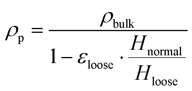 | (2) |
 | (3) |
The particle size distribution has been measured by means of a Beckman Coulter laser diffraction particle analyser.
Atomic layer deposition
Alumina-supported Pt catalysts have been implemented for hydrogen oxidation at room temperature. After drying the alumina powder in a static oven at 120 °C over night, the coating of the particles has been performed by means of atomic layer deposition. The ALD synthesis has been carried out at atmospheric pressure in a vibrated fluidized bed.34 The trimethyl(methylcyclopentadienyl)platinum(IV) (Pt(MeCp)Me3) has been selected as Pt precursor.34 The ALD experiments consist of a sequence of four steps. In the first step, the precursor is fed at 0.5 L min−1 to the reactor, consisting of a glass cylindrical column of 2.54 cm diameter. To do so, a nitrogen stream (99.999% v/v) is saturated with the precursor vapours by flowing through the precursor bubbler heated at 70 °C. Then, this saturated stream in introduced to the fluidized bed of alumina particles, transported through stainless steel tubing lines kept at 30 °C above the bubbler temperature to avoid undesired condensation. Once the precursor enters the reactor, it diffuses through the bed of the porous alumina particles, effectively chemisorbing on the alumina surface. Consequently, the higher the exposure time of the alumina to the precursor, the larger the amount of chemisorbed precursor, until saturation of the alumina surface takes place. In the second step, the residues of the precursor and of the chemisorption by-products are purged with a nitrogen stream. In the third step, pure oxygen is fed to the reactor to burn the organic ligands of the Pt precursor, achieving the desired Pt coating as Pt nanoclusters. In the last step, the excesses of oxygen and combustion by-products are purged as well. During the whole ALD experiment the reactor has been operated at 300 °C.34 Batches of 4 g of alumina powder have been used for all the synthesized Pt loadings, leading to a bed of 4 mm in a 5.08 cm diameter reactor. The fluid-like state of the particles has been ensured by working with a velocity slightly above the minimum fluidization one, and the mixing has been promoted with the vibration of the bed. Depending on the desired Pt loading, single or multiple sequential ALD cycles have been performed (up to 5 cycles), each one consisting in the four illustrated steps. Each cycle has been carried out by exposing the alumina to the precursor for a variable time between 2 and 40 min, depending on the desired loading. However, the purging times (step 2 and 4) and the oxygen exposure times have been kept constant for all the performed ALD experiments and equal to 10 min. Successively, the powder has been analysed by means of the scanning electron microscopy (SEM) catching any morphological change of the particles derived by the ALD procedure.Characterization of the catalytic powder
After the synthesis of the Pt catalyst with different metal loadings, the weight percentage of Pt for each ALD batch has been evaluated by means of the inductively coupled plasma optical emission spectrometry (ICP-OES). Approximately 0.03 g of coated alumina have been destructed in a mixture of 4.5 mL of 30% HCl, 1.5 mL of 65% HNO3 and 0.2 mL of 40% HF by means of the microwave Multiwave PRO. After 60 min, the sample has been diluted in 50 mL of MilliQ water and analysed with a PerkinElmer Optima 5300 DV optical emission spectrometer.After the characterization of the Pt loading, the size distribution of the Pt nanocluster, deposited with the ALD experiments onto the alumina surface, has been assessed with transmission electron microscopy (TEM) images of the catalytic alumina surface. In particular, a sample of approximately 0.1 g has been crushed, successively diluted in ethanol and, then, dispersed onto the copper TEM grid of 3.05 mm diameter. The TEM images of several different catalyst portions have been performed by means of a JEOL JEM-1400 electron microscope operating at 120 kV, with a field of view of few tens of nanometers.
Catalytic tests
The catalytic hydrogen oxidation reaction (eqn (4)) has been selected being a process active at ambient temperature, which allows for characterisation of intermediate regimes between the full chemical and the external mass transfer depending on the operating conditions. | (4) |
![[thin space (1/6-em)]](https://www.rsc.org/images/entities/char_2009.gif) :85). Two thermocouples have been placed immediately before and after the bed to evaluate the inlet and outlet temperatures. The gas stream exiting from the reactor is dried through a bed of silica granules to adsorb the produced water. Then, the outlet H2 and O2 compositions has been analysed by means of the ESS mass spectrometer.
:85). Two thermocouples have been placed immediately before and after the bed to evaluate the inlet and outlet temperatures. The gas stream exiting from the reactor is dried through a bed of silica granules to adsorb the produced water. Then, the outlet H2 and O2 compositions has been analysed by means of the ESS mass spectrometer.
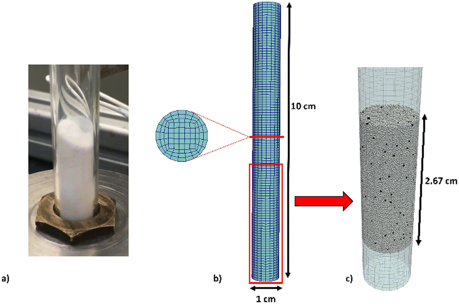 | ||
| Fig. 1 1 cm diameter lab scale reactor: a) reactor filled with alumina particles; b) computational grid with the detail of the cross section; c) outcome of the initial packing procedure of the sphere diameter distribution (black particles are the active ones, loaded with Pt, 1:85 dilution is represented in the picture). It is worth noticing that a 1 cm height has been meshed before the packed bed in order to impose the inlet boundary conditions sufficiently far from the beginning of the packed bed. | ||
Computational methods
This section describes the multiscale CFD–DEM methodology, the computational domain representing the experimentally operated lab scale fluidized bed, and the adopted boundary conditions.Methodology
The numerical simulations have been carried out by means of the multiscale reactive CFD–DEM modeling approach developed in our previous works,19,23,24 whose governing equations are reported in detail in the ESI† (section S2). The framework predicts the evolution of the catalytic fluidized bed by means of the solution of both the solid and gas phases at each time step of the simulation. First, the solid phase is solved particle-wise by considering the gas phase frozen. Each particle is tracked by means of the LIGGGHTS®35,36 particle tracking algorithm. This tracking algorithm has been selected due to its higher efficiency with respect to the one present in OpenFoam,37 which allows a 11-fold reduction of the non-reactive simulation computational cost. On top of this, the species, site species and energy balances are solved particle-wise accounting for both the gas–particle mass/energy transfer and the catalytic reactions. Once the solid phase is updated, the gas–particle momentum, mass and energy transfer terms are evaluated for each computational cell and the gas phase fields are evolved by considering the solid phase frozen. The update of pressure and velocity fields is performed by solving the Navier–Stokes equations by means of the PIMPLE algorithm, while the gas composition and temperature ones by accounting for the species and energy conservation equations.Computational domain
The lab-scale reactor adopted in the experimental runs (Fig. 1a) and reproduced in the numerical simulations (Fig. 1b and c) is a cylinder with a 1 cm diameter and 10 cm height. The simulations are carried out by considering the experimentally measured particle distribution.Fig. 1b reports the computational grid with a cell-to-particle diameter ratio of 3 with respect to the average particle diameter and 2 with respect to the maximum particle diameter observed in the solid granulometry. Fig. 1c reports the results of the initial packing procedure by means of the DEM particle tracking algorithm. At the beginning of the procedure, the computational domain is empty, and the particles are injected from the top of the reactor. The packing simulation has been stopped once a steady-state packing has been obtained on the basis of the recorded particle velocities, i.e. maximum velocity below 10−4 m s−1.
Table 1 lists the bed and the particle properties in the simulation. In particular, it reports the minimum, maximum and average particle diameters of the experimentally measured size distribution reported in the ESI† (section S1). Additionally, further details on the measurement of the friction factor and the catalytic particle density are given in the following Results and discussion section, while the particle restitution coefficient has been selected equal to 0.8 from the alumina data available in work of Gorham and Kharaz.38
| Catalytic bed properties | |
|---|---|
| Particle diameter Dp [μm], min/max/average | 150/500/300 |
| Particle density ρp [g cm−3] | 1.36 |
| Particle number Np [−] | 83767 |
| Mechanical properties | |
|---|---|
| Young modulus E [MPa] | 3 |
| Poisson ratio ν [−] | 0.22 |
| Restitution coefficient e [−] | 0.8 |
| Friction factor μ [−] | 0.542 |
The following boundary conditions have been selected. At the bottom of the reactor, i.e. the inlet, the velocity corresponding to the experimental flow rate to be reproduced has been imposed, together with the adopted composition reported in the Catalytic tests section. No slip conditions have been imposed at the reactor walls as well as a zero gradient condition for the species and for pressure. At the top of the reactor, i.e. the outlet, atmospheric pressure has been imposed as well as fully developed profiles for both velocity and species. The temperature has been set equal to 296 K, i.e. room temperature, in the whole domain. Indeed, isothermal simulations have been performed since the maximum experimentally determined temperature difference in the reactor is below 5 K.
Each reactive CFD–DEM simulation has been carried out for at least 10 residence times with a first-order chemical kinetic, whose parameter is evaluated in the Results and discussion section, to achieve the pseudo-steady state. To deal with the intrinsic oscillations of the composition at the outlet of the reactor, caused by the bubbling of the fluidized bed, the following procedure has been adopted to obtain the reported CFD conversion data. Each numerically predicted conversion of oxygen has been computed by time averaging the oxygen mass fraction at the outlet of the reactor, obtained by means of cup-mix average, for at least three residence times at the pseudo-steady state.
Results and discussion
This section discusses the outcomes of the experimental and computational campaigns. First, the synthesis and characterizations of the catalyst is presented to evaluate the inputs needed to properly reproduce the system through a multiscale model and to collect the information necessary to derive a kinetic constant at the selected operating conditions. Then, after a validation of the multiscale tool, the capability of this approach is shown both in term of fluid dynamic and chemistry behaviour.Mechanical characterization of alumina particles
The particle friction factor is measured by means of the angle of repose test. Fig. 2 shows the pyramid formed by the alumina particle after that the maximum reposing mass is reached. This pyramid is characterized by a repose angle equal to 28.5 ± 1° which leads to a particle friction factor of 0.542 ± 0.024.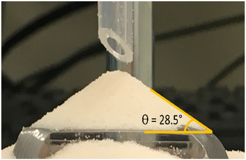 | ||
| Fig. 2 Image resulting from the angle of repose tests of the alumina particles. | ||
With respect to the particle density (ρp), the fixed bed bulk density of the alumina particles is equal to 0.84 g cm−3. After the packing of the three different beds of 12 g of particle, the heights have been measured obtaining a value equal to 2.60 cm for the normal configuration, 2.43 cm for the dense configuration and 2.67 cm for the loose one, and the pressure drop vs. velocity tests have been run.
Fig. 3 reports the measured pressure drops as a function of the inlet superficial velocities. The symbols are the experimentally measured pressure drops for both the dense (blue squares) and loose (red circles) configurations, while the solid lines represents the pressure–velocity trends obtained by fitting the Ergun equation in case of the dense (blue line) and loose (red line) pressure drop points (i.e. the ones below the 70% of the minimum fluidization velocity). A value equal to 0.357 and 0.392 for dense and loose packing respectively. Finally, the particle density has been computed from the two bed void fractions. A particle density of 1.36 g cm−3 is obtained in both the configurations, confirming the reliability of the adopted procedure.
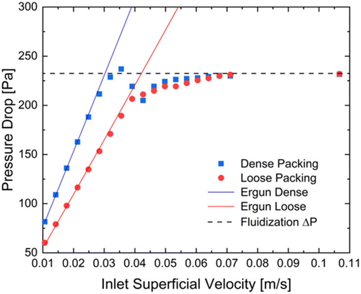 | ||
| Fig. 3 Experimentally measured pressure drop (closed symbols) and pressure drop resulting from the Ergun equation (solid lines) as a function of the inlet superficial velocity, considering a glass reactor of 2.54 cm diameter and 12 g of alumina particles with average diameter of 296 μm, for the dense (blue) and loose (red) packed bed. The dashed black line reports the theoretical minimum fluidization pressure drop of 232 Pa. | ||
At last, an average alumina particle diameter of 300 μm has been found (with d50 equal to 290.1 μm). The whole distribution has been reported in the ESI† (section S1).
Catalyst synthesis and characterization
The catalytic particles adopted in this study has been synthesized by means of the ALD procedure as described in the Experimental methods section. Fig. 4 shows the obtained Pt contents percentage (measured by means of ICP-OES analysis) as a function of the Pt precursor exposure time and number of ALD cycles. Among the obtained Pt contents, the 1% (blue circle) and 2.3% (red circle) loadings have been used in the experimental and modeling campaigns. Fig. 4a shows the Pt weight percentage as a function of the exposure time of the alumina particles to the Pt precursor during 1 ALD cycle. At low exposure times, a constant Pt deposition rate is expected from ALD coating of surfaces of non-porous materials.26 However, an initially increasing rate is obtained, typically absent in the coating of non-porous surfaces,26 which is related to the presence of diffusional phenomena. Instead, at sufficiently high exposure times, the Pt percentage is no more increasing, as expected, since the surface reaction is self-limiting. After considering the Pt weight percentage as a function of the exposure time of the alumina particle to the precursor, we performed different ALD experiments with an increasing number of ALD cycles. In particular, during each ALD cycle, the solid particles have been exposed to the precursor for 20 minutes. Fig. 4b shows the obtained Pt percentage as a function of the number of ALD cycles performed. In the first cycle, 2.3% of Pt have been deposited, whereas a constant deposition rate of 1.2% Pt weight percentage per ALD cycle has been obtained as expected by increasing the number of cycles. This has been ascribed to the slower diffusion of the Pt precursor in the alumina pores already partially covered by Pt after the first ALD cycle. Indeed, lower diffusion rate leads to lower deposition rate and hence less Pt can be deposited in the same amount of exposure time per cycle, i.e. 20 minutes.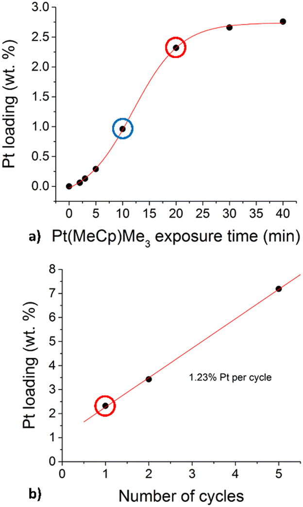 | ||
| Fig. 4 Deposited Pt weight percentage as a function of the exposure time of the alumina to the Pt precursor (a) and the number of the performed ALD cycles (b). | ||
Fig. 5 shows an example of the comparison between SEM images of bare alumina particles (reported on the top) and the Pt loaded one (on the bottom) randomly chosen from the respective batches. The images indicate that no significant differences are present between the two batches. Consequently, no relevant particle breakage or deformation are caused by the vibrated fluidization adopted in the ALD experiments (average circularity and roundness of the particles measured with ImageJ39 software equal to 0.96 and 0.92 for bare alumina and 0.96 and 0.88 for coated one, thus close to 1, obtained in case of perfect spheres).
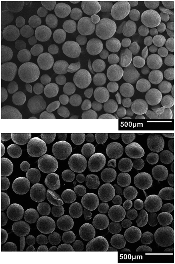 | ||
| Fig. 5 Comparison of the SEM image of two samples from two different batches: bare alumina (top) and alumina loaded with Pt (bottom). | ||
Given the consistent Pt loadings obtained after the ALD procedure, we proceeded with the characterization of the catalytic particles. In particular, we characterized the size of the Pt nanoparticles obtained on the alumina surface.
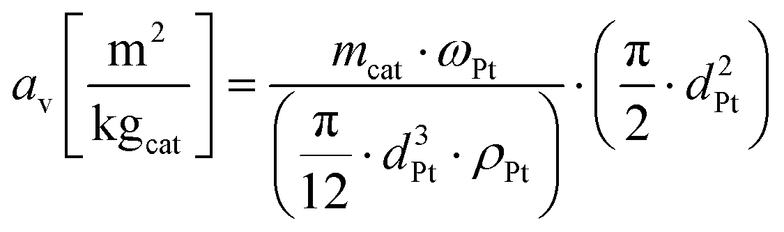
Fig. 6 shows an example of the TEM images of the fragments of the alumina particles loaded with 2.3% Pt (Fig. 4a, red circle). The TEM image allows for detecting the Pt nanoclusters (Fig. 6, dark spots) and thus to quantify their area by means of the ImageJ39 software. Then, the Pt nanoparticle diameters have been computed from the nanoparticle area assuming their shape as perfect hemispheres. Table 2 reports the computed Pt nanoparticle average diameter for all the Pt loadings highlighted in Fig. 4, as long as their consequent specific surface area av in m2 per kg of supported catalyst (kgcat) computed according to eqn (5).
 | (5) |
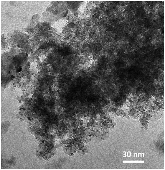 | ||
| Fig. 6 Example of the TEM images of the Pt/Al2O3 catalyst. The dark spots are the Pt nanoclusters deposited during the ALD experiments. | ||
| Pt loading ωPt [% w/w] | Average diameter dPt [nm] | Specific catalytic surface [m2cat kg−1] |
|---|---|---|
| 1.0 | 1.99 | 1406 |
| 2.3 | 2.52 | 2221 |
Derivation of kinetic model by means of experimental runs performed in fixed bed operating mode
After the synthesis and characterization of the catalytic particles, catalytic tests in the fixed bed operating mode has been performed in the 1 cm diameter glass reactor. The same dilution (ratio 1:85) adopted for the reactive fluidized bed tests in case of 1% Pt has been employed to derive the kinetic model for H2 oxidation over Pt with oxygen as limiting reactants. These catalytic tests have been performed at room temperature, adopting the same feed composition selected for the reactive fluidized bed tests (H2 = 0.5% and O2 = 0.2% in nitrogen). A kinetic model with a first order dependency from oxygen40 has been selected and the kinetic constant at room temperature (k[296]) has been derived by reproducing the fixed bed experiments. The 1D heterogeneous model, reported in eqn (6) and (7), has been chosen to reproduce the fixed bed date since it accounts for both kinetics and gas–solid mass transfer effects and thus it can allow us to derive the kinetic constant also considering data that are not collected in full chemical regime. | (6) |
 | (7) |
 and
and  are the molar flow rate and concentration of oxygen in the gas phase,
  is the concentration of oxygen in the solid phase, Kc,O2 is the mass transfer coefficients and Sw is the geometric surface of the solid particles per unit of catalyst mass. The Reichelt correlation has been selected considering the good agreement of the experimental data reported in literature for the investigated range of particle Reynolds numbers [1.8–9.2].41,42
Fig. 7 reports as symbols the measured oxygen conversions at different inlet velocities, also corresponding to the ones used in the fluidized catalytic tests, while the red dashed line reports the oxygen conversions resulting from the fitting of the kinetic constant by means of the measured conversions (symbols) and the 1D heterogeneous model applied with an oxygen first order expression kinetics and the Reichelt correlation, leading to a kinetic constant at room temperature (k[296]) equal to 2.18 ± 0.03 [m3 kgcat−1 s−1] (95% confidence interval). After the evaluation of the kinetic constant, the Damköhler number has been computed for all the experimental data used for the fitting and value ranging from 0.55 and 0.8 have been obtained. As expected the experimental data are not in full chemical regime due to the high reactivity of the Pt catalyst, highlighting the needs of an heterogeneous model to properly evaluate the kinetic constant.
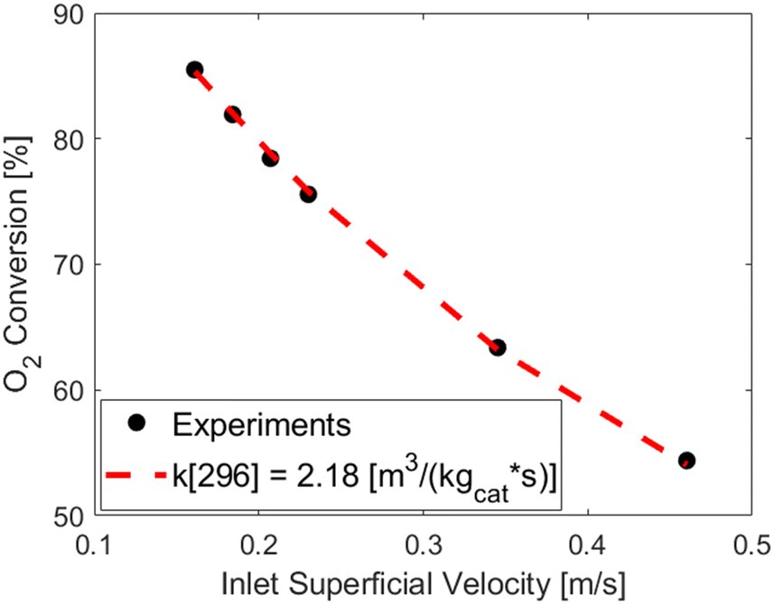 | ||
| Fig. 7 Trend of the oxygen conversion obtained in the 1 cm diameter lab scale reactor operated in fixed bed operating mode (ratio 1:85). Experimental measurements are reported as black circles, while the dashed red line reports the trend obtained by fitting the kinetic constant by means of the 1D heterogeneous model. | ||
This derived k[296] has been then used as input in the multiscale simulation, together with the Reichelt correlation for the gas–particle mass transfer, for modeling the lab-scale fluidized bed.
Validation of the framework on the basis of the measured and numerically predicted macroscopic conversions
The experimental and computational investigation of the catalytic fluidized system has been carried out in the 1 cm diameter reactor with 1:85 dilution ratio. Fig. 8 shows as lines and closed symbols the experimentally measured conversions of oxygen in the range 0.4–2 L min−1 (9.2–46 cm s−1), corresponding to fluidization ratios 2.5–13. Two different Pt loadings have been tested to investigate the system at different hydrogen oxidation reactivities. A Pt loading of 1% is considered consistently with the one adopted in the fixed bed tests for the fitting of the kinetic constant. Then, a higher Pt loading equal to 2.3% has been considered. To account for the higher loading, the kinetic constant k[296] derived for the 1% Pt has been scaled by the ratio of the specific catalytic surfaces, reported in Table 2, leading to a kinetic constant for the 2.3% Pt (k2.3%[296]) equal to 3.44 [m3 kgcat−1 s−1]. The open symbols in Fig. 8 represents the results of the CFD–DEM simulations at four different inlet superficial velocities for the two different Pt loadings, while the black symbols indicates the fully external mass transfer limited conversions, achieved by increasing the kinetic constant of three order of magnitudes.
 | ||
| Fig. 8 Comparison between the O2 conversion measured in the experimental runs of the lab scale fluidized bed (line with closed symbols) and the one obtained by means of the reactive CFD–DEM framework (open symbols) as a function of the inlet superficial velocity for the 1% (blue) and 2.3% (red) Pt loadings. The closed black symbols report the conversion results obtained by assuming fully external mass transfer conditions (kinetic constant multiplied by 1000). | ||
An excellent agreement has been obtained (maximum error of 5% and 4% for 1% and 2.3% Pt respectively) over a wide range of operating velocities which leads to different fluidization regimes, ranging from the bubbling bed resulting at the lowest simulated flow rate (i.e. 0.5 L min−1) to the slugging regime observed at high flow rates (above 0.7 L min−1). Additionally, by reducing the feed velocity the importance of the mass transport resistances becomes more and more relevant and the multiscale framework is always capable to correctly reproduce the mutual interactions between kinetic and species transport.
Furthermore, the excellent agreement achieved in case of the 2.3% Pt catalyst, confirms the reliability of the derived kinetic constant. Indeed, this kinetic constant have been derived directly from the 1% one by considering just the ratio of measured specific surfaces, and no-additional fitting have been needed.
Hence, the framework has demonstrated reliable at different inlet velocities, and in particular, at different fluidization and chemical regimes, and consequently it can be adopted to assist the experimental campaign by adding fundamental understanding of the investigated reactor unit and process, as discussed in the following section.
Fundamental understanding provided by the first-principle multiscale model
The multiscale framework can assist the experimental campaign since it enables both a qualitative and quantitative dive into the reactor environment allowing for a deeper understanding of both the fluid dynamic and chemical phenomena evolving in the unit. In particular, the distribution of the solid phase and the gas species inside the fluidized system according to the inlet flowrate can be observed as reported in Fig. 9 where the solid phase (blue color) and oxygen maps in a vertical plane of the reactor for the 1% Pt simulations are shown. All the four numerically investigated velocities are reported, as well as six different time frames for each velocity collected during the pseudo-steady state evolution of the unit.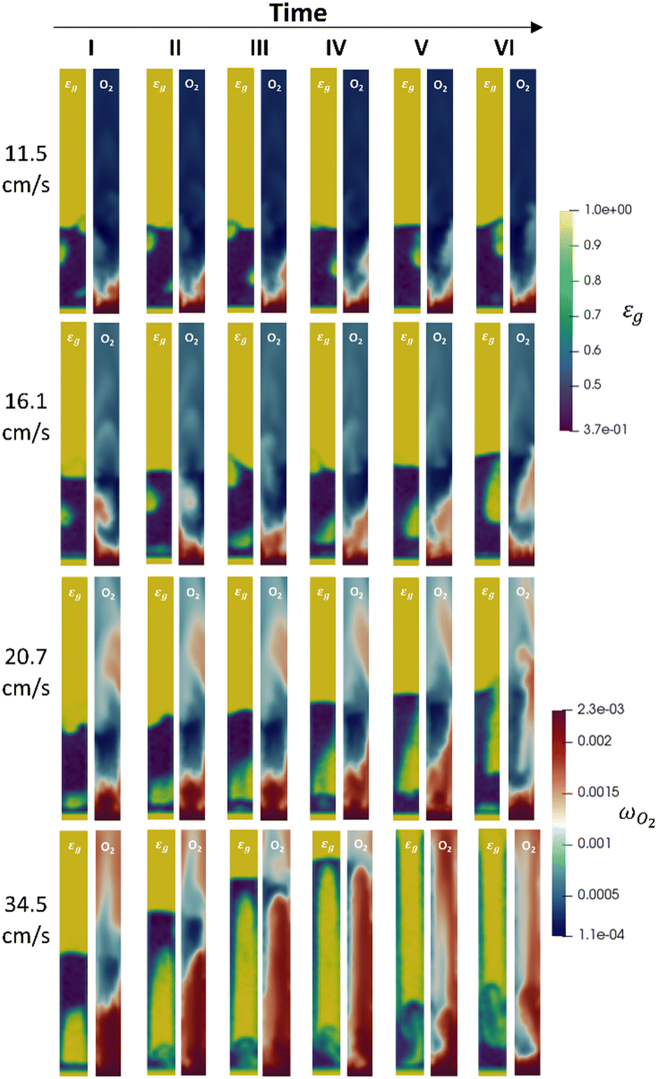 | ||
| Fig. 9 Snapshots of the void fraction εg and oxygen maps reported for a central vertical plane of the lab scale reactor. Each line represents a temporal sequence of snapshots for a specific velocity, and all the four velocities numerically investigated, i.e. 11.5, 16.1, 20.7 and 34.5 cm s−1, are shown. | ||
With respect to the analysis of the multiphase fluid dynamics of the system, is possible to identify the different fluidization regimes obtained in the reactor as a function of the operating velocity. At the lowest one, the typical bubbling behaviour of a Geldart B28 powder can be observed. In particular, the reactor is characterized by small bubbles generated close to the gas inlet, e.g. the one at the bottom right of the plane, and constantly growing in diameter along the fluidized bed.
By increasing the velocity at 16.1 cm s−1, a transition between the bubbling and the slugging regime is observed. Indeed, on the one hand, bubbling behaviour is still clearly distinguishable from the first two snapshots where a bubble is rising and growing on the left side of the plane. On the other hand, this situation is alternated with the generation of a gas piston at the bottom of the fluidized bed. However, it rapidly turns into a large growing elongated bubble frames (III–VI), since the velocity is still not sufficiently high for the insurgence of a full slugging regime. With respect to the 20.7 cm s−1 velocity, the slugging phenomenon is observable. Pistons of gas generate at the bottom of the reactor and move upward in the bed (frames I–III), even if there is still the formation of a large elongated bubble occupying the major part of the bed height (frames IV–VI). Finally, the transition from the bubbles of gas to the cluster of particles arises at the 34.5 cm s−1. In this condition, a piston of gas is generated at the bottom of the reactor, pushing upward a piston of solid with a lateral raining of particles, as reported in the I frame. The solid piston thins during the upward movement due to the lateral particle raining, until a thin layer of solid is present at the top of the gas piston and a fluidized bed is observable at the bottom (frame III–IV). This behaviour is alternated with a vigorously fluidized dense phase breaking into solid spots, i.e. the blue regions representing the cluster of particles (frame V–VI).
The first-principles multiscale model thus can provide additional insights into the reactor environment that can be hardly or cannot be achieved through experiments. Indeed, on the one hand, it can be used to help or even replace expensive device that are able to monitored the movement of the solid phase inside the unit, such as X-ray tomography. On the other hand, it can allow for the understanding of how the fluid dynamic structures influences the reactivity of the system. Here, for example, the amount of reactants and products within the bubbles and the emulsion can be quantified without experimental invasive methods (e.g. in situ probing) enabling to identify the presence of transport resistances. Indeed, the reactant species predominantly flow through the bed in gas bubbles (yellow regions in the void fraction maps of Fig. 9), and they must reach emulsion (blue regions in the void fraction maps of Fig. 9) before arriving to the catalyst surface through the particles boundary layer. In this view, an investigation on the importance of this mass transfer resistance can be performed by observing the oxygen mass fraction maps reported for each velocity and frame in Fig. 9. This mass transfer resistance becomes more and more important by increasing the inlet flowrate. Starting from the lowest velocity, the transfer resistance between the bubble and the emulsion, is evident from the oxygen gradient between the two regions, as highlighted by the light red spots of oxygen at the same position of the bubble. Similarly to the 11.5 cm s−1 velocity, oxygen rich bubbles are still present due to bubble–emulsion mass transfer limitations, and higher oxygen concentrations in the bubble and more pronounced oxygen gradients can be observed, coherently with the increment of the bubbles diameters. In the case of the 20.7 cm s−1 velocity, high oxygen concentrations close to the feed one are observed in the bubbles due to the decreased surface to volume ratio of the bubbles which reduces the species exchange between the gas bubbles and the emulsion phase. However, as for the other velocities, the typical mixing inside the emulsion phase is still present with a homogeneous oxygen distribution observed in this region for all the snapshots avoiding the presence of another possible transport resistance related to the position of the catalytic particles inside the emulsion. Finally, at the 34.5 cm s−1 velocity, a relevant by-pass of the bed is observed for the gas phase, leading to streams of reacted oxygen coming from the dense phase and clusters alternate periodically with stream of almost unreacted oxygen.
Beyond the qualitative analysis of the macroscale mass transfer resistances, e.g. the bubble–emulsion ones, additional insights are provided by the framework with respect to the interplay of the different mass transfer resistances and catalytic reactions. In particular, the importance of three mass transfer resistances can been evaluated. The first one which accounts for the species transport between the bubble and the emulsion (i.e. bubble–emulsion resistance), the second one considers the species gradient between the emulsion and the catalytic particle surface (i.e. gas–particle resistance), while the third one results from the combination of the other two resistances (i.e. overall resistance). The importance of each resistance has been quantified by means of the ratio between the oxygen mass fraction at the end point of the species transfer and the oxygen fraction at the starting point of the species transfer, according to the following equations:
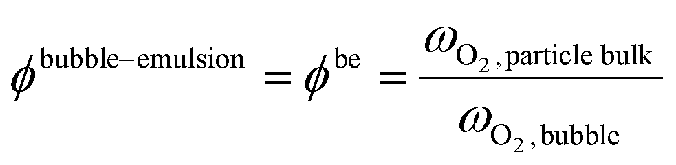 | (8) |
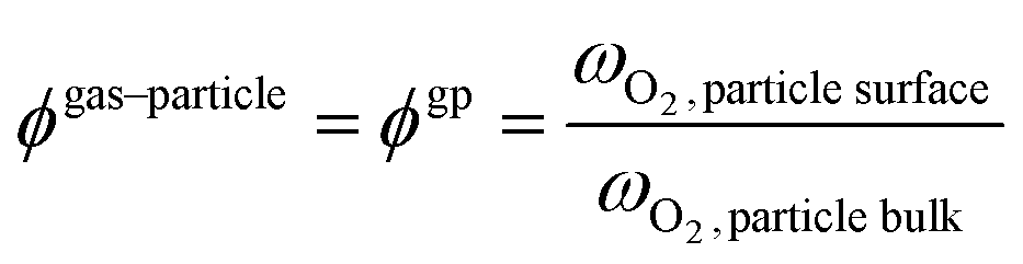 | (9) |
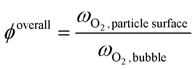 | (10) |
Fig. 10 shows a reactor cross section characterized by relevant bubble area for the 11 cm s−1 velocity. The active particles located in the considered section for the selected time frame have been reported and colored on the basis of the importance of the considered mass transfer resistance (ϕgp and ϕbe). The gas phase of the cross section is indeed colored on the basis of the oxygen mass fraction evidencing the mass transfer limitations observed in Fig. 9. Indeed, a red oxygen rich area can be identified at the right side of the cross section coherently with the bubble position observable in the solid distribution map reported aside of the cross section. Then, a relevant oxygen gradient is present until the oxygen poor area in dark blue is reached far from the bubble.
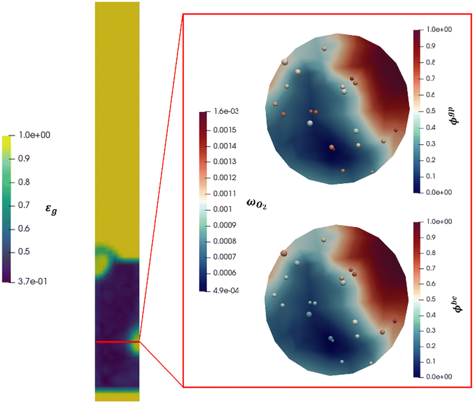 | ||
| Fig. 10 Detail of a cross section of the lab scale reactor for the 11.5 cm s−1 velocity. On the left, the void fraction map is reported for a central vertical plane of the reactor to show the height at which the cross section is analysed. On the right, the same cross section is reported twice and the gas phase is colored on the basis of the oxygen mass fraction. However, in the upper right image, the active particle located in the cross section are colored on the basis of the gas–particle mass transfer limitation, while, in the bottom right image, they are colored on the basis of the bubble–emulsion mass transfer limitation. | ||
First, the ϕoverall have been computed for all the active particles, obtaining an average value of 0.29, thus confirming the importance of mass transfer resistances in the investigated system, but excluding at the same time a fully external mass transfer regime coherently with the experimental observations in Fig. 8, where a change in the Pt loading has produced a non-negligible change in the oxygen conversion for the same operating conditions.
Then, each single mass transfer mechanisms have been analysed. In the upper cross section image of Fig. 10, the particles are colored on the basis of the gas–particle ϕ number, whereas in the bottom image of the cross section, the particles are classified on the basis of the bubble–emulsion ϕ number. Two different spatial trends are observed for the two ϕ numbers. As expected, ϕgp is independent from the location of the active particle with respect to the bubble. This contribution is mainly influenced by the specific surface of the particle, leading to value close to 1 for the smallest particles (e.g. 150 μm) until 0.5 for the one with the largest ones (e.g. 500 μm). Thus, the value of ϕgp increases by decreasing the particle diameter. On the other hand, a clear pattern emerges for ϕbe. Its value is strongly dependent on the distance between the center of the bubble and the location of the particle in the emulsion and, in particular, it decreases by increasing the distance. Indeed, the active particles located near to the bubble–emulsion interface are characterized by ϕbe close to 1, while the ϕbe value of the ones present in the center of the emulsion can be also equal to 0.2.
Conclusions
In this work, we show the potential of the combination of multiscale modeling and experiments for the analysis of complex reactive systems, such as catalytic fluidized ones. In particular, a 1 cm diameter lab scale fluidized bed has been both experimentally run and simulated by considering hydrogen oxidation over Pt catalyst. First, the experimental campaign allows for both the synthesis via atomic layer deposition and characterization of the catalyst to obtain the chemical and mechanical properties needed to computationally reproduce the considered system. Then, experimental investigations both in fixed and fluidized bed configuration have been carried out. On the one hand, the fixed bed data have been used to derive a kinetic model for the hydrogen oxidation over Pt catalyst at the selected operating conditions (e.g. ambient temperature and with oxygen as limiting reactant). On the other hand, the fluidized bed experiments allow for the identification of the effect of the feed conditions on the performance of the units and to collect data to assess the multiscale approach. Indeed, after the experimental campaign, the same operating conditions have been numerically reproduced. The measured and predicted oxygen outlet conversions have been compared obtaining an excellent accuracy by means of the reactive CFD–DEM model (maximum deviation of 5%) showing the reliability of a first-principles based approach in describing complex reactive environment. Therefore, an example of the information that can be obtained through a numerical investigation have been finally reported. In particular, the change of the fluid dynamic behaviour of the units can be identified according to the inlet conditions and related to the oxygen distributions and the presence of mass transfer resistances. The latest can be indeed both qualitative identified by looking at the species maps inside the system or quantitative analysed to understand the predominant one.As a whole, the work has proven the capability of the adopted numerical investigation, after an experimentally-driven evaluation of the mechanical and chemical properties of the catalytic particles, in analysing the phenomena inside the reactor, which can be extended to arbitrary complexity geometries and kinetic mechanisms given the multiscale nature of the developed and adopted framework. Consequently, this paves the way for the analysis of novel fluidization concepts, e.g. pulsed or confined beds, in the context of heterogeneous catalytic processes and for the refinement of the multiscale models of industrial fluidized units.
Author contributions
Riccardo Uglietti: conceptualization, experimental campaign, numerical investigation, methodology, writing – original draft; Daniele Micale: conceptualization, numerical investigation, methodology, writing – original draft; Damiano La Zara: conceptualization, experimental campaign, writing – review and editing; Aris Goulas: experimental campaign, writing – review and editing; Luca Nardi: experimental campaign; Mauro Bracconi: conceptualization, methodology, supervision, writing – review and editing; J. Ruud van Ommen: conceptualization, supervision, funding acquisition, project administration, writing – review and editing; Matteo Maestri: conceptualization, supervision, funding acquisition, project administration, writing – review and editing.Conflicts of interest
There are no conflicts to declare.Acknowledgements
M. M., R. U., M. B., D. M. and L. N. acknowledge support by the European Research Council (ERC) under the European Union's Horizon 2020 research and innovation programme (Grant Agreement no. 814416/ReaxPro: “Software Platform for Multiscale Modelling of Reactive Materials and Processes”). R. U. acknowledges the support by the IDEA League Student Grant. Sasol Germany GmbH is gratefully acknowledged to have provided the alumina porous particles used to manufacture the catalyst used in this study. Computational time at CINECA, Bologna (Italy) is gratefully acknowledged.Notes and references
- J. Aronsson, E. Krymarys, V. Stenberg, T. Mattisson, A. Lyngfelt and M. Rydén, Energy Fuels, 2019, 33, 4442–4453 CrossRef CAS.
- A. Cruellas, T. Melchiori, F. Gallucci and M. van Sint Annaland, Energy Technol., 2020, 8, 1900148 CrossRef CAS.
- M. P. Dudukovic, Science, 2009, 325, 698–701 CrossRef CAS PubMed.
- A. Bruix, J. T. Margraf, M. Andersen and K. Reuter, Nat. Catal., 2019, 2, 659–670 CrossRef CAS.
- G. D. Wehinger, M. Ambrosetti, R. Cheula, Z.-B. Ding, M. Isoz, B. Kreitz, K. Kuhlmann, M. Kutscherauer, K. Niyogi, J. Poissonnier, R. Réocreux, D. Rudolf, J. Wagner, R. Zimmermann, M. Bracconi, H. Freund, U. Krewer and M. Maestri, Chem. Eng. Res. Des., 2022, 184, 39–58 CrossRef CAS.
- M. Maestri, Chem. Commun., 2017, 53, 10244–10254 RSC.
- M. Maestri and A. Cuoci, Chem. Eng. Sci., 2013, 96, 106–117 CrossRef CAS.
- T. Maffei, G. Gentile, S. Rebughini, M. Bracconi, F. Manelli, S. Lipp, A. Cuoci and M. Maestri, Chem. Eng. J., 2016, 283, 1392–1404 CrossRef CAS.
- M. Bracconi, M. Ambrosetti, M. Maestri, G. Groppi and E. Tronconi, Chem. Eng. J., 2018, 352, 558–571 CrossRef CAS.
- C. Ferroni, M. Bracconi, M. Ambrosetti, M. Maestri, G. Groppi and E. Tronconi, Ind. Eng. Chem. Res., 2021, 60, 10522–10538 CrossRef CAS.
- S. Rebughini, A. Cuoci and M. Maestri, Chem. Eng. J., 2016, 289, 471–478 CrossRef CAS.
- M. Bracconi, Chem. Eng. Process., 2022, 181, 109148 CrossRef CAS.
- P. Zhao, J. Xu, B. Zhao, D. Li and J. Wang, Powder Technol., 2022, 407, 117651 CrossRef CAS.
- S. Du, J. Wang, Y. Yu and Q. Zhou, Renewable Energy, 2023, 202, 483–498 CrossRef CAS.
- H. Luo, X. Wang, X. Liu, X. Wu, X. Shi and Q. Xiong, J. Anal. Appl. Pyrolysis, 2022, 162, 105433 CrossRef CAS.
- D. Kong, S. Wang, K. Luo, J. Yu and J. Fan, Fuel, 2023, 338, 127292 CrossRef CAS.
- Z. Wan, S. Yang, J. Hu and H. Wang, Fuel, 2022, 327, 125208 CrossRef CAS.
- L. Molignano, M. Troiano, R. Solimene, S. Tebianian, F. Scala, P. Salatino and J.-F. Joly, Fuel, 2023, 341, 127590 CrossRef CAS.
- R. Uglietti, M. Bracconi and M. Maestri, React. Chem. Eng., 2018, 3, 527–539 RSC.
- M. A. van der Hoef, M. van Sint Annaland, N. G. Deen and J. A. M. Kuipers, Annu. Rev. Fluid Mech., 2008, 40, 47–70 CrossRef.
- T. Tanaka, T. Kawaguchi and Y. Tsuji, Int. J. Mod. Phys. B, 1993, 07, 1889–1898 CrossRef.
- N. G. Deen, M. Van Sint Annaland, M. A. Van der Hoef and J. A. M. Kuipers, Chem. Eng. Sci., 2007, 62, 28–44 CrossRef CAS.
- D. Micale, C. Ferroni, R. Uglietti, M. Bracconi and M. Maestri, Chem. Ing. Tech., 2022, 94, 634–651 CrossRef CAS.
- R. Uglietti, M. Bracconi and M. Maestri, React. Chem. Eng., 2020, 5, 278–288 RSC.
- R. Uglietti, D. Micale, M. Bracconi and M. Maestri, in CFB 2021 – Proceedings of the 13th International Conference on Fluidized Bed Technology, 2021, pp. 251–256 Search PubMed.
- J. R. van Ommen and A. Goulas, Mater. Today Chem., 2019, 14, 100183 CrossRef CAS.
- H. Van Bui, F. Grillo and J. R. van Ommen, Chem. Commun., 2017, 53, 45–71 RSC.
- D. Geldart, Powder Technol., 1973, 7, 285–292 CrossRef CAS.
- K. Wu, L. de Martín and M.-O. Coppens, Chem. Eng. J., 2017, 329, 4–14 CrossRef CAS.
- B. Mahmoodi, S. H. Hosseini, M. Olazar and H. Altzibar, J. Taiwan Inst. Chem. Eng., 2017, 81, 275–287 CrossRef CAS.
- A. Bahramian and M. Olazar, Chem. Eng. Res. Des., 2021, 176, 34–48 CrossRef CAS.
- I. Mema and J. T. Padding, Chem. Eng. Sci.: X, 2020, 8, 100079 CAS.
- D. Micale, R. Uglietti, M. Bracconi and M. Maestri, Ind. Eng. Chem. Res., 2021, 60, 6687–6697 CrossRef CAS PubMed.
- F. Grillo, H. Van Bui, D. La Zara, A. A. I. Aarnink, A. Y. Kovalgin, P. Kooyman, M. T. Kreutzer and J. R. van Ommen, Small, 2018, 14, 1800765 CrossRef PubMed.
- C. Kloss, C. Goniva, A. Hager, S. Amberger and S. Pirker, Prog. Comput. Fluid Dyn., 2012, 12, 140–152 CrossRef.
- C. Goniva, C. Kloss, N. G. Deen, J. A. M. Kuipers and S. Pirker, Particuology, 2012, 10, 582–591 CrossRef.
- H. G. Weller, G. Tabor, H. Jasak and C. Fureby, Comput. Phys., 1998, 12, 620 CrossRef.
- D. A. Gorham and A. H. Kharaz, Powder Technol., 2000, 112, 193–202 CrossRef CAS.
- C. A. Schneider, W. S. Rasband and K. W. Eliceiri, Nat. Methods, 2012, 9, 671–675 CrossRef CAS PubMed.
- R. W. Schefer, Combust. Flame, 1982, 45, 171–190 CrossRef CAS.
- E. Reichelt, M. Jahn and R. Lange, Chem. Ing. Tech., 2017, 89, 390–400 CrossRef CAS.
- F. Scala, Chem. Eng. Sci., 2013, 91, 90–101 CrossRef CAS.
Footnotes |
| † Electronic supplementary information (ESI) available: Particle size distribution, reactive CFD–DEM multiscale framework. See DOI: https://doi.org/10.1039/d3re00152k |
| ‡ The authors contributed equally to this work. |
| This journal is © The Royal Society of Chemistry 2023 |