 Open Access Article
Open cell foam materials as Pd reservoirs for Suzuki–Miyaura coupling catalysis at ppb level†
Amira
Jabbari-Hichri
a,
Amine
Bourouina
 a,
Pierre-François
Biard
b,
Audrey
Denicourt-Nowicki
 b,
Alain
Roucoux
 b,
Marie-Line
Zanota
a,
Fabrice
Campoli
a,
Claude
de Bellefon
 *a and
Valérie
Meille
 *c
*c
aUniversité de Lyon, Institut de Chimie de Lyon, Laboratory of Catalysis, Polymerization, Processes & Materials, CP2M UMR 5128 CNRS-UCB Lyon 1-CPE Lyon, CPE Lyon 43 Bd du 11 Novembre 1918, F-69616 Villeurbanne, France. E-mail: cdb@lgpc.cpe.fr
bUniv Rennes, Ecole Nationale Supérieure de Chimie de Rennes, CNRS, ISCR - UMR6226, F-35000 Rennes, France. E-mail: pierre-francois.biard@ensc-rennes.fr
cUniv Lyon, Université Claude Bernard Lyon 1, CNRS, IRCELYON, F-69626, Villeurbanne, France. E-mail: valerie.meille@cnrs.fr
First published on 6th April 2023
Abstract
For the Suzuki–Miyaura C–C coupling, it is well accepted that the active catalytic species in the liquid phase are leached from the solid palladium precursor. This was demonstrated for shaped solid Pd precursors which allows fixed-bed applications in flow chemistry. Yet, many interesting solid Pd precursors, including supported nanoparticles (NPs), are available as finely divided powders that cannot be used in fixed-bed reactors because of the too high pressure drop generated. In this work, open cell foam materials (OCF) are used as supports for Pd/C, Siliacat-Pd(0) and Pd(II)-DPP catalysts powders and Pd(0) NPs. The coupling of 4-iodoacetophenone with phenylboronic acid is used as a model reaction to evaluate the activity of leached species. Some experiments with other aryl halides are also reported. It is shown that all the catalytic foams are able to leach active species and that trace amounts in the range 30–300 ppb of Pd in solution are sufficient to carry out the reaction while maintaining a low pressure drop.
1 Introduction
The Suzuki–Miyaura carbon–carbon coupling, catalysed by palladium, is of paramount importance in the chemical and pharmaceutical industries. Due to the need to avoid the presence of palladium in the products, lots of studies were dedicated to the development of heterogeneous catalysts. However, recent studies have allowed to conclude that Pd leaching, even of traces amounts, was responsible for all or part of the catalytic activity.1–8 A particular set-up was developed to highlight the role of leached species on the catalytic activity of C–C coupling reactions.9,10 This “split-flow reactor” consists of a catalytic packed bed, followed by an empty tube, with an efficient filtration between both sections. In the case of the Suzuki–Miyaura reaction, the catalytic column was demonstrated to be a reservoir of hyperactive catalytic species which were able to leach and further react in the empty tube section.10 Our objective was to check whether this phenomenon was encountered regardless of the catalyst used, could it be Pd(0) or Pd(II). Nonetheless, using a packed-bed was not adapted to all kinds of catalysts. As an example, it was not possible to test a Pd/carbon powder in this configuration because the pressure drop through the column rapidly exceeded the maximum pressure limits of the HPLC pump (220 bar). To circumvent similar pressure drop issues, Nagaki et al.11 proposed to use polymer monolithic reactors with large pores to run a continuous production. Recently, McMillin et al. designed a three dimensional polymer printing fixed bed reactor for continuous Suzuki cross-coupling reactions.12In our case, it was decided to extend the use of the split-flow device to the testing of catalytic open cell foams (OCF). Catalytic OCF are now widely used for process intensification due to the high mass and heat transfer and low pressure drop they offer.13–16
2 Experimental section
2.1 Reagents
The reagents used for the experiments are: 4-iodoacetophenone, 3-iodoacetophenone, 4-iodoanisole, 4-bromoacetophenone, 4-chloroacetophenone, phenylboronic acid and sodium methoxide, all from Acros Organics. The solvent used for all these experiments is anhydrous ethanol (CARLO ERBA). All chemical products were used without purification or treatments.2.2 OCF catalytic columns
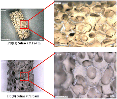
Different kinds of OCF were used. The variety of foams includes metallic foams coated with Pd/C (Pd/C@OCF) and with 2 Pd Siliacat materials (Pd(0) Siliacat@OCF and Pd(II) Siliacat@OCF) and one glass foams impregnated with zerovalent Pd nanoparticles (Pd(0) NPs@OCF).2.3 Reaction
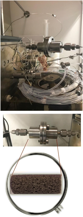
For the catalytic Suzuki–Miyaura reaction (see Fig. 3), a reagent solution was prepared by dissolution of 4-iodoacetophenone (1.53 g, 0.01 mole, 1 eq.), phenylboronic acid (0.9 g, 0.012 mole, 1.2 eq.), MeONa (0.5 g, 0.015 mole, 1.5 eq.) and naphthalene (GC standard, 0.5 g, 0.003 mole, 0.3 eq.) in ethanol (250 mL). The solution is then homogenized by using an ultrasound bath for 60 min at room temperature. The prepared solution is then pumped with a previously fixed flow rate by using HPLC pump (Shimadzu LC-20AP) through the preheated (60 °C) catalytic column containing the foam and then was filtered (2 μm) and allowed to circulate in PFA tubes (1.7 mm int. diameter, SWAGELOK PFA-T2-030-100). One to six sections of PFA tubes were placed at the exit of the OCF section, each of them measured 1 to 10 m and allowed sampling, resulting in a maximum of 7 samples per test (one at the exit of the column and up to 6 for the tubes). An example is schematized in Fig. 4.2.4 Analyses
The evolution of the catalytic reaction is followed through different samples taken on the several sections of the set-up. The catalytic solution collected from the set-up is then quenched in deionized water (2 mL) and ethyl acetate (Sigma Aldrich) (1 mL). This mixture allows to separate the reagents and consequently to stop the catalytic reaction. Then the heavier organic phase was collected, dried over MgSO4 (Sigma Aldrich) and filtered through celite 545 (ROTH). Then the collected solution is analyzed by using GC-FID chromatography Agilent Technologies 6890 N, column OPTIMA 5 (10 m × 100 μm × 0.1 μm), split 1/400 volume injected 1 μL (100 °C), flow H2: 20 mL min−1, program oven: 100 °C (30 s) then 50 °C min−1 up to 290 °C (90 s), FID detector. Naphthalene (Acros Organics) was used as an internal standard. The chromatographic analysis (GC-FID) is used to study the kinetics of the catalytic reaction and to follow the evolution of the concentration of the reactants and products at each section of the set-up. To carry out this study, different calibration curves were made for the reagents and products. The amount of leached palladium in solution was measured at Glincs (Villeurbanne, France) following the protocol below: first, after collecting 0.4 mL of catalyst solution at the outlet of the catalytic column in a sterile tube (50 mL, guaranteed metal free), an addition of 5 mL of 10% nitric acid containing 2 ppb of indium ion, used as an internal reference, was done. To homogenize the solution, the sample is then placed in an ultrasonic bath at 80 °C for 1 h. Then the obtained solution is diluted by the same nitric acid + indium ion solution until a total volume of 40 mL is reached. The final solution obtained is then placed again in the ultrasonic bath at 80 °C for 1 h and then left to cool before being analysed by ICP-MS (Nexion 2000, Perkin Elmer).3 Results and discussion
3.1 Coated FeCrAl foams
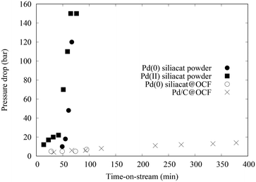
The different coated foams were used in the catalytic column to catalyze the coupling of 4-iodoacetophenone with phenylboronic acid. In addition, one PFA tube of 1 m long was placed at the exit of the catalytic column, after the filter. In the case of Pd/C@OCF, containing 71 mg of 5 wt% Pd/C, the pressure in the system remained under 15 bar after 7 hours of test, contrasting drastically with experiments using powder catalysts (Fig. 5). The conversion at the Pd/C@OCF column outlet was stable during the test performed at 1 mL min−1, at a mean value of conversion of 30% while that at the tube outlet was 50%. Note that the reaction was selective and only produced 4-acetylbiphenyl with all the tested catalysts. It was checked that the concentration of Pd at the tube outlet (0.3 ppm according to ICP/MS analysis in the 6 h product collection), and responsible for the catalytic activity at least in the PFA tube section, was due to leaching and not to fine particle detachment, which indicates that the catalyst was well adherent to the OCF. Concerning Pd(0) Siliacat and Pd(II) Siliacat@OCF, the conversion at the set-up outlet was doubled compared to that at the column outlet, from 13% to 23% and from 24% to 44% respectively (Table 1).| Entry | Catalyst@OCF | t col (min) | X col (%) | t tube (min) | X tube (%) | [Pd] (pbb) |
|---|---|---|---|---|---|---|
| 1 | Pd/C@OCF | 1.5 | 26 | 2.1 | 46 | 360 |
| 2 | Pd(0) Siliacat@OCF | 1.5 | 13 | 2.1 | 23 | n.d. |
| 3 | Pd(II) Siliacat@OCF | 0.75 | 24 | 1.1 | 44 | n.d. |
| 4 | Pd(0) NPs@glass | 9.5 | 68 | 20 | 99 | 33 |
The observed pressure drop remained below 10 bar for all the tested conditions. Note that both Pd(0) and Pd(II) Siliacat catalysts were also tested as powder catalysts in packed bed column thanks to moderate pressure drops for these materials (Fig. 5).10 The rapid increase of pressure drop while using powder packed beds can be explained by two hypotheses. First, the formation of iodide and boronate salts can crystallize in the bed porosity; second, some fine particles can be formed by the destructive role of pressure on the particle bed. The activity results obtained with the powder or foam are consistent.
3.2 Catalytic glass foam
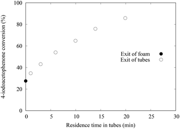
Similar experiments were performed in the set-up dedicated to the test of the catalytic glass OCF. At the outlet, not only one PFA tube was installed but 6 tubes, allowing sampling at each intersection (see Fig. 2). The length of the tubes is in the range of 0.5 to 3 m which gives a cumulative length of up to 10 m.An example of 4-iodoacetophenone conversion measured at the different points of sampling is presented in Fig. 6. The first point corresponds to the column foam exit, the other ones to the exit of each PFA tube.
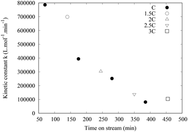
The main results are reported in Table 1. Note that the residence times are much different than for the metallic OCF objects since the size of the OCF is different and the length of PFA tubing also. Here, the conversion increased from 27 to 86% in the tube sections, thanks to Pd species that were leached out of the OCF. The 27% conversion in the column is due to the quite long contact time of ca. 10 min during which leaching occurs leading to conversion in the column. Although the nature of the catalytic species is not well known, it is not due to mechanical attrition. Indeed, the integrity of the glass OCF is preserved. Also, no powder is deposited, formation of micrometric solid particles is not observed and would lead to pressure drop increase at the filter placed at the exit of the column. The pressure drop never exceeded 12 bars. The reactor was used for consecutive runs. Several concentrations of reactants were used and the flowrate was maintained at 1 mL min−1. For all the experiments, the concentration of Pd in the tube was measured at ca. 30 ppb, 10 times lower than with the previous Pd/C@foam, thus demonstrating that a very small amount of Pd is sufficient to catalyse the reaction as previously described.10 The complete series lasted 10 h, with a constant leaching of 30 ppb (measured by ICP/MS). Thus, only 0.5% of the Pd coated on the glass OCF was leached after 10 h on stream. However, even if the concentration of leached species was stable, their activity was found to decrease rapidly. This is quantified by the decrease of the conversion measured at the exit of the column from 70% to 17% after several runs using the same columns (see ESI† Table_S3). To further quantify this deactivation phenomenon, kinetic constants were evaluated, based on the hypothesis that the kinetic model established for the Suzuki–Miyaura coupling with a palladacycle homogeneous catalyst would be the same for the leached active species.20r = k[ArI][Pd] where [ArI] is the concentration of the aryl halide and [Pd] is the Pd concentration in the liquid (leached species). A concentration of 30 ppb was used for the estimation. For each experiment, a parameter estimation was made using the version 4.27 of COPASI (COmplex PAthway SImulator),21 considering the entry of the first tube as initial conditions (initial time, ArI initial concentration and Pd leached concentration) and a plug flow behaviour in the tubes. Kinetic constants were estimated for the different sets of experiments and are represented in Fig. 7. It can be seen that the kinetic constant decreases drastically with time-on-stream, although freshly leached species are generated continuously.
Considering the reaction rate law, the results could be explained by a decrease of the concentration of active species with time-on-stream, the intrinsic constant k keeping the same value. The total Pd concentration analysed by ICP-MS includes both the concentration of active and inactive Pd species. The reasons why more inactive Pd species are generated with time is not yet understood but several hypotheses can be speculated. Since the total leached Pd concentration is constant with time, it is proposed that the leaching mechanism is the same, leading initially to a large quantity of active species.
However, with time, we speculated that at least two phenomena could occur, one being named “the ad-atom deactivation mechanism”, the other named “the ligand coordination deactivation mechanism”. 1) For the “ad-atom” mechanism, we hypothesized that the surface of the Pd crystallites leading to the leached species could change. In particular, single Pd atoms or “adatoms” could be formed at the Pd surface. It is speculated that these single Pd(0) atoms could react with the Pd(II) active species leading to inactive bi- or poly nuclear Pd species. For example, it has been reported that reaction of Pd(II) complexes with Pd(0) complexes leading to binuclear Pd(I) is one synthetic route to Pd(I) complexes.22 Whereas binuclear Pd(I) complexes bearing phosphine ligands have been reported to be active in Suzuki coupling,23 Pd(I) binuclear complexes having no phosphine ligands are not so active, displaying similar activities than Pd(OAc)2.24 Thus here, the deactivation mechanism would be due to Pd itself. 2) For the ligand coordination deactivation mechanism we hypothesized that with time, some species such as salts or other side products of the reaction adsorb and accumulate on the OCF material. These species would not change the leaching phenomenon but would react with the leached species leading to inactive yet soluble Pd compounds. This would explain why the total Pd concentration is constant with time-on-stream while a clear decrease of conversion is observed. Studies of the deactivation mechanism of soluble Pd catalysts in C–C coupling reactions are scarce and the investigation of such mechanisms at trace amount of Pd species is a real challenge to be tackled.
3.3 Other aryl halides
To demonstrate the versatility of the set-up, 2 other iodoaryl compounds were used with one of the foams (Pd/C@OCF). The results are presented in Table 2. In the case of 4-iodoanisole, the reaction was not selective. The yield in 4-methoxybiphenyl was much lower than the conversion. Nevertheless, it was shown that the yield increased between the end of the OCF column and the end of empty tube, once again showing that leached species were responsible for the catalytic activity. Concerning 3-iodoacetophenone, at a first sight, the performances may look similar to that of 4-iodoacetophenone in Table 1, but using a residence time 5 times greater. The reaction rate is lower due to the meta position of iodide but the behavior in terms of leaching and selectivity are the same. Some experiments concerning bromo- and chloroaryls are also presented in Table 2, although they were not obtained with foams. First, it is observed that the selectivity of both 4-bromo- and 4-chloroacetophenone couplings is not 100%. A leaching of ca. 200 ppb of Pd was measured in both cases, nevertheless, no conversion/yield increase was observed in the case of the chloro compound after its stay in the tube, as we have already published.10 This result may be due to a very rapid deactivation of the leached Pd species. Finally, 4-bromoacetophenone shows an intermediate behavior between 4-iodo- and 4-chloroacetophenone.![[thin space (1/6-em)]](https://www.rsc.org/images/entities/char_2009.gif) :
:![[thin space (1/6-em)]](https://www.rsc.org/images/entities/char_2009.gif) 1) for ArI, pure EtOH for others). tcol and ttube are the residence times in the column and empty tube respectively, Xcol and Xtube are the ArX conversion measured at the column outlet and at the column + tube outlet respectively, [Pd] is the leached Pd concentration measured at the tube outlet
1) for ArI, pure EtOH for others). tcol and ttube are the residence times in the column and empty tube respectively, Xcol and Xtube are the ArX conversion measured at the column outlet and at the column + tube outlet respectively, [Pd] is the leached Pd concentration measured at the tube outlet
| Reactant | Catalyst (mg Pd) | t col (min) | X col (yield) (%) | t tube (min) | X tube (yield) (%) | [Pd] (ppb) |
|---|---|---|---|---|---|---|
| 4-Iodoanisole | Pd/C@OCF (3.5) | 7.5 | 24 (5) | 10.5 | 29 (10) | n.d. |
| 3-Iodoacetophenone | Pd/C@OCF (3.5) | 7.5 | 32 (31) | 10.5 | 54 (53) | n.d. |
| 4-Bromoacetophenone | Pd(II) Siliacat (0.6) | 0.08 | 12 (5) | 7.2 | 16 (9) | 230 |
| 4-Chloroacetophenone | Pd(II) Siliacat (11) | 0.42 | 47 (33) | 2.6 | 48 (34) | 170 |
4 Conclusion
In conclusion, the Pd@OCF materials are interesting catalyst precursors in the Suzuki–Miyaura coupling for flow chemistry applications. OCF materials can cope to some extent the formation of some insoluble salts side products without pressure drop building. Also, the presence of trace amount of palladium as low as 30 ppb in the product solution complies with regulations on metal contents in the product. Besides these technical advantages, some key questions remain to be solved. In particular, only a small amount of the Pd contained in the solid precursor is used. Also, the deactivation of the soluble active species with the process time (time on stream) is hardly explainable. Further studies are on progress on these topics.Author contributions
Conceptualization, formal analysis and validation: AJH, AB, CDB, VM; methodology, funding acquisition, project administration and supervision: CDB, VM; resources: FC, MLZ, PFB, ADN, AR; visualization and writing original draft: AJH, AB, PFB, CDB, VM; writing review and editing: AJH, AB, PFB, CDB, VM.Conflicts of interest
There are no conflicts to declare.Acknowledgements
The authors would like to acknowledge the French ANR for the funding of the project HYPERCAT (ANR-18-CE07-0021). Frédéric Bornette is warmly thanked for his contribution in the reactor design. Ronan Lebullenger and Annabelle Couvert are also warmly thanked for their participation in the glass foam synthesis.Notes and references
- S. S. Soomro, F. L. Ansari, K. Chatziapostolou and K. Köhler, J. Catal., 2010, 273, 138–146 CrossRef CAS.
- C. Deraedt and D. Astruc, Acc. Chem. Res., 2014, 47, 494–503 CrossRef CAS PubMed.
- G. Collins, M. Schmidt, C. O'Dwyer, J. D. Holmes and G. P. McGlacken, Angew. Chem., Int. Ed., 2014, 53, 4142–4145 CrossRef CAS PubMed.
- A. Del Zotto and D. Zuccaccia, Catal. Sci. Technol., 2017, 7, 3934–3951 RSC.
- A. Bourouina, V. Meille and C. de Bellefon, Catalysts, 2019, 9, 60 CrossRef.
- B. Sun, L. Ning and H. C. Zeng, J. Am. Chem. Soc., 2020, 142, 13823–13832 CrossRef CAS PubMed.
- D. Roy and Y. Uozumi, Adv. Synth. Catal., 2018, 360, 602–625 CrossRef CAS.
- G. Hamasaka, D. Roy, A. Tazawa and Y. Uozumi, ACS Catal., 2019, 9, 11640–11646 CrossRef CAS.
- E. M. Barreiro, Z. Hao, L. A. Adrio, J. R. van Ommen, K. Hellgardt and K. K. M. Hii, Catal. Today, 2018, 308, 64–70 CrossRef CAS.
- A. Bourouina, V. Meille and C. de Bellefon, J. Flow Chem., 2018, 8, 117–121 CrossRef CAS.
- A. Nagaki, K. Hirose, Y. Moriwaki, M. Takumi, Y. Takahashi, K. Mitamura, K. Matsukawa, N. Ishizuka and J.-I. Yoshida, Catalysts, 2019, 9, 300 CrossRef.
- R. E. McMillin, B. Clark, K. Kay, B. F. Gupton and J. K. Ferri, Int. J. Chem. React. Eng., 2023, 21, 313–327 CrossRef CAS.
- L. Vanoye, B. Guicheret, C. Rivera-Cárcamo, R. Castro Contreras, C. de Bellefon, V. Meille, P. Serp, R. Philippe and A. Favre-Réguillon, Chem. Eng. J., 2022, 441, 135951 CrossRef CAS.
- N. Benamara, D. Assoua, L. Jaffeux, L. Vanoye, F. Simescu-Lazar, M.-L. Zanota, F. Bornette, V. Meille and I. Pitault, Processes, 2018, 6, 117 CrossRef.
- G. Chen, X. Zhu, R. Chen, Q. Liao, D. Ye, H. Feng, J. Liu and M. Liu, Chem. Eng. J., 2017, 334, 1897–1904 CrossRef.
- J.-N. Tourvieille, R. Philippe and C. de Bellefon, Chem. Eng. J., 2015, 267, 332–346 CrossRef CAS.
- M.-L. Zanota, S. Pallier, A. Dousse, J. Lachambre and V. Meille, ChemEngineering, 2018, 2, 52 CrossRef CAS.
- F. Simescu-Lazar, T. Chaieb, S. Pallier, L. Veyre, R. Philippe and V. Meille, Appl. Catal., A, 2015, 508, 45–51 CrossRef CAS.
- A. Cabrol, A. Lejeune, R. Lebullenger, A. Denicourt-Nowicki, A. Roucoux, A. Couvert and P.-F. Biard, Chem. Eng. Res. Des., 2021, 168, 453–464 CrossRef CAS.
- A. Bourouina, A. Oswald, V. Lido, L. Dong, F. Rataboul, L. Djakovitch, C. de Bellefon and V. Meille, Catalysts, 2020, 10, 989 CrossRef CAS.
- S. Hoops, S. Sahle, R. Gauges, C. Lee, J. Pahle, N. Simus, M. Singhal, L. Xu, P. Mendes and U. Kummer, Bioinformatics, 2006, 22, 3067–3074 CrossRef CAS PubMed.
- N. Hazari and D. P. Hruszkewycz, Chem. Soc. Rev., 2016, 45, 2871–2899 RSC.
- C. Fricke, T. Sperger, M. Mendel and F. Schoenebeck, Angew. Chem., Int. Ed., 2021, 60, 3355–3366 CrossRef CAS PubMed.
- X. Han, Z. Weng and T. S. A. Hor, J. Organomet. Chem., 2007, 692, 5690–5696 CrossRef CAS.
Footnote |
| † Electronic supplementary information (ESI) available. See DOI: https://doi.org/10.1039/d3re00111c |
| This journal is © The Royal Society of Chemistry 2023 |

