 Open Access Article
A liquid-phase continuous-flow peptide synthesizer for preparing C-terminal free peptides†
Yuma
Otake
 *a,
Kyohei
Adachi
a,
Yoshiaki
Yamashita
a,
Natsumi
Iwanaga
a,
Hirokatsu
Sunakawa
a,
Taiki
Shamoto
a,
Jun-ichi
Ogawa
a,
Atsushi
Ito
a,
Yutaka
Kobayashi
b,
Keiichi
Masuya
b,
Shinichiro
Fuse
 c,
Daisuke
Kubo
a and
Hidenosuke
Itoh
a
aYokogawa Electric Corp, Musashino, 180-8750, Japan. E-mail: Yuuma.Otake@yokogawa.com
bPeptiDream, Inc., Kawasaki, 210-0821, Japan
cDepartment of Basic Medicinal Sciences, Graduate School of Pharmaceutical Sciences, Nagoya University, Nagoya, 464-8601, Japan
First published on 16th December 2022
Abstract
Despite the importance of peptide drugs, their production has been usually performed by unsustainable and time-consuming methods. Conventional peptide production requires repeated amidation and deprotection steps that increase the amount of waste and the time and effort required. Therefore, in this study, we developed an automated continuous-flow liquid-phase peptide synthesizer for the preparation of C-terminal free peptides for the first time. Our synthesizer comprises an amidation unit with a micro-flow reactor, an extraction unit with mixer settlers, a concentration unit with a thin-layer evaporator, and a control unit. A crude dipeptide, Fmoc-Ala-Phe-OH, and a tripeptide, Fmoc-Ala-Phe-Phe-OH, that was directly obtained from the crude dipeptide, were synthesized using our system. The steadiness of the flow system was continuously monitored by measuring the process parameters, namely the flow rate, pressure, and temperature. The peptide synthesis was monitored using a near-infrared (NIR) sensor. Our strategy enabled the first liquid-phase continuous-flow peptide synthesis, including aqueous workup and concentration, and the in-line NIR monitoring of peptide-bond formation. Thus, it will contribute to enhancing efficiency in peptide production.
Introduction
Peptide drugs are attractive candidates for drug discovery and development. To date, 80 peptides have been commercialized in the global market, 150 peptides are in clinical development, and 400–600 peptides are in preclinical studies.1 However, time-consuming and unsustainable preparation methods of peptides using large amounts of reagents and solvents have been frequently used.2 Therefore, time- and labor-efficient and eco-friendly peptide synthesis is essential.3The most conventional peptide synthesis involves repeated amidation and deprotection steps (Scheme 1a). Thus, approximately half of the steps in peptide synthesis are deprotection steps, which increase the time and effort required for the synthesis in addition to the amount of waste. To solve these problems, two types of synthetic approaches for C-terminal free peptides have been developed: (1) the first strategy involves C- and N-terminal free amino acids as nucleophiles for peptide chain elongation (Scheme 1b-i).4 In 1881, Curtius reported the first chemical peptide synthesis using C- and N-terminal free glycine.4a Although this strategy can reduce the synthesis time, unprotected amino acids are usually soluble only in water, and the use of an aqueous solvent tends to cause undesired hydrolysis at the C-terminus of activated amino acids during amidation, which generates C-terminal free amino acids as by-products. In some cases, this side reaction complicates the separation of the desired peptide and by-product. (2) The second strategy involves a temporarily protected amino acid, whose protecting group is removed during the workup process (Scheme 1b-ii). In 1992, Bambino et al. reported the use of a trimethylsilyl (TMS) group as a temporary protecting group for peptide synthesis.5 Several other studies have reported the use of TMS-protected amino acids or peptides for the synthesis of C-terminal free peptides.6 These reactions can be performed in organic solvents, and thus undesired hydrolysis is avoided.
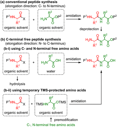 | ||
| Scheme 1 Conventional peptide synthesis and C-terminal free peptide synthesis. X: leaving group, P: protecting group. | ||
Continuous manufacturing is advantageous over batch manufacturing in terms of economy, product quality, safety, and environmental friendliness.7 Continuous-flow peptide syntheses have been reported over the last two decades.8 Automation of chemical processes improves scalability, safety, efficiency, and reproducibility9 and is compatible with continuous-flow synthesis.9,10 Pentelute et al. developed an automated continuous-flow solid-phase peptide synthesizer that produces long peptides in a relatively short time.11 Continuous-flow liquid-phase peptide synthesis is more suitable than solid-phase peptide synthesis for the large-scale production of peptides in terms of cost and waste. However, an automated system for continuous-flow liquid-phase peptide synthesis has not been reported thus far.
Process analytical technology (PAT)12 is useful not only for understanding reactions in detail but also for monitoring and controlling continuous manufacturing.13 In-line optical sensors are one of the most powerful PAT tools that can analyze the reaction solution in continuous-flow systems in real-time.14 Ultraviolet-visible (UV-vis) spectroscopy has been successfully used in continuous-flow solid-phase peptide synthesis to detect the eliminated fluorenyl moiety during the removal of the Fmoc group.15 However, an appropriate in-line analytical method for continuous-flow, liquid-phase peptide synthesis has not been established to date. Ishigaki et al. recently demonstrated the near-infrared (NIR) spectroscopic analysis16 of some pure amino acids and peptides in water or dimethyl sulfoxide (DMSO) and identified their absorbances, which are useful for the quantitative analysis of liquid-phase peptide synthesis.17 However, reaction solutions contain various organic solvents, reagents, and substrates. Therefore, further examinations are necessary to demonstrate the utility of in-line NIR monitoring for continuous-flow liquid-phase peptide synthesis.
Fuse et al. reported the micro-flow synthesis of C-terminal free peptides based on the strategy shown in Scheme 1b-i.4d Rapid amidation between mixed carbonic anhydrides and C- and N-terminal free amino acids or peptides has been demonstrated. Masuya et al. recently reported C-terminal free peptide synthesis based on the strategy shown in Scheme 1b-ii.6c They demonstrated the practical synthesis of a wide variety of N-methylated peptides mediated by an isostearic acid halide and in situ silylated N-methyl amino acids. Therefore, based on these previously reported synthetic strategies, in this study, we developed an automated continuous-flow peptide synthesizer equipped with an amidation unit with a micro-flow reactor, an extraction unit with mixer-settlers, and a concentration unit with a thin-layer evaporator. These were operated using a control unit that we developed. Amidation was performed using the strategy shown in Scheme 1b-ii, which involves the coupling of mixed carbonic anhydrides and amino acids that were temporarily protected by TMS groups. In addition, the continuous-flow peptide synthesis was monitored using a NIR sensor.
Design of the continuous-flow peptide synthesizer
Our peptide synthesizer consists of four units—amidation, extraction, concentration, and control units (Fig. 1 and S8 in the ESI†). The amidation unit has high-performance liquid chromatography (HPLC) pumps with valves for reagents, solvents, and methanol (for washing). The operation status of the HPLC pumps was monitored by pressure and flow rate sensors. Fmoc-amino acid/peptide (Fmoc-AA-OH) was mixed with an activating agent (isobutyl chloroformate, IBCF) in the first T-shaped mixer. The activated amino acid/peptide was then mixed with a temporary silylated amino acid (TMS-AA-OTMS) in the second T-shaped mixer to afford an elongated peptide. The T-shaped mixers (made of stainless steel) and reaction tubes (made of polytetrafluoroethylene, PTFE) were immersed in a water bath to ensure rapid heat exchange. Temperatures of the reaction mixtures before and after mixing the reagents were measured using thermocouples inserted upstream and downstream of the T-shaped mixers.18 These temperature sensors monitored the amount of heat generated during the reaction. The NIR spectra of the reaction solutions were measured using an in-line flow cell installed downstream of the amidation reaction tube. The detailed procedure for the NIR measurements is described below.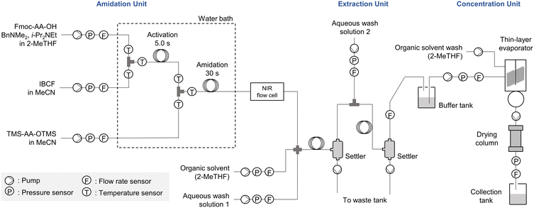 | ||
| Fig. 1 Schematic of the developed continuous-flow peptide synthesizer comprising amidation, extraction, and concentration units. | ||
The extraction unit consists of mixers, tubes, and settlers for liquid–liquid extraction. Diaphragm pumps were used to introduce an organic solvent and aqueous solutions into the flow system as well as to discharge aqueous waste from the settler and control the settler-liquid level. At the end of the extraction process, the obtained liquid was collected in a buffer tank.
The concentration unit was built using a commercially available thin-layer evaporator. A pump was attached to the evaporator to introduce the extract from the buffer tank. A thin-layer evaporator has rotors that form a thin layer of liquid to promote evaporation. The resultant concentrate dripped into the reservoir of the evaporator. The end point of evaporation was detected by the flow sensor, and the concentrate was pumped into a collection tank. The inner wall of the thin-layer evaporator was washed with the solvent, and the washing solution was pumped into the collection tank.
The control unit consisted of subunits, the main controller, and a computer. The subunits have various interfaces (RS-232C, RS-485, and analog I/O) that allow communication with the pumps, sensors, and valves. The sensing values and device statuses were sent to the main controller via the subunits. The data processed by the main controller were sent to a computer and displayed. A synthetic “recipe”, which describes the setting values and events of each device, created in the computer was processed in the main controller and sent to each device via the subunits. The entire system can be easily expanded by increasing the number of subunits because the main controller is designed to accommodate multiple subunits.
Results and discussion
Optimization of the amidation reaction
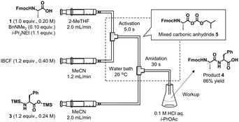
First, we optimized the amidation reaction conditions using a simple flow reaction system consisting of syringe pumps, PTFE tubes, mixers, and a water bath (Fig. 2). The synthesis of Fmoc-Ala-Phe-OH (4) from Fmoc-Ala-OH (1) and H-Phe-OH (2) was employed as a model reaction. Although a known protocol was applied to our flow system,6c,d the solvent for dissolving carboxylic acid 1 was changed from MeCN to 2-methyltetrahydrofuran (2-MeTHF) because MeCN was optimized for batch reactions in a previous study.6c To use the crude C-terminal free peptide for subsequent peptide chain elongation, the solvent (1) should not prevent amidation, (2) should be easily separated from water in the extraction step, and (3) should be able to dissolve peptides at high concentrations at the concentration step. Therefore, we used 2-MeTHF as the solvent for carboxylic acid 1. Mixed carbonic anhydride 5 was generated in situ from 1 and IBCF within 5 s in the presence of a catalytic amount of BnNMe2.19 We preliminarily examined the use of isopropyl chloroformate that was used in a previous study,19 which exhibited performance comparable to that of IBCF (see section 3-2 in the ESI†). Hence, we selected readily available IBCF. IBCF was dissolved in MeCN because MeCN can dissolve the HCl salt of i-Pr2NEt that is generated in the reaction. Bis-silylated amino acid 3 was prepared from H-Phe-OH (2) and the silylating agent N,O-bis(trimethylsilyl)acetamide (BSA) in a batch reactor. Compound 3 and the mixed carbonic anhydride 5 were mixed and reacted in the flow reactor for 30 s and collected in the flask. After aqueous workup and recrystallization, the desired 4 was obtained in 86% yield. Preliminary examination revealed that a higher temperature (60 °C) reduced the yield owing to an undesired reaction (see section 3-5 in the ESI†).We also investigated the maximum permissible water content (wt%) during the amidation reaction of carboxylic acid 1 and compound 3. The carboxylic acid solution obtained after amidation, extraction, and concentration should contain a certain amount of water. The influence of residual water on amidation was evaluated by measuring the purity of the reaction mixture. Less than 0.2 wt% water in the substrate solution did not significantly prevent amidation (Table 1, entries 1–3). More than 1 wt% water in the solution caused precipitation, probably owing to the water-mediated undesired desilylation of amino acids (entry 5).
Synthesis of peptides using the continuous-flow peptide synthesizer
Next, we continuously operated the amidation, extraction, and concentration units in the newly developed continuous-flow peptide synthesizer. The amidation unit was operated as described in the previous section. The reaction solution obtained from the amidation unit was mixed with 2-MeTHF and aq. HCl, which was then passed through the extraction tube for 20 s to wash the organic layer (Fig. 3). These conditions afforded results comparable to those of the batch extraction (see section 4 in the ESI† for the preliminary results). The mixture of the organic and aqueous layers was separated in the settler, and the obtained organic layer was washed with aq. NaCl in the same manner. After separation in the second settler, the organic layer was collected for 83 min to obtain 920 mL of the extract. The amount of solvent consumed in this process was ∼1.4 L. The purity of compound 4 was 96% (area% determined by HPLC-UV analysis), indicating that the amidation and extraction processes were successful.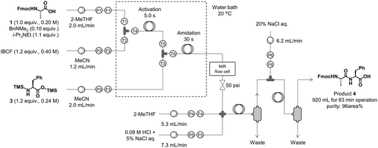 | ||
| Fig. 3 Synthesis and extraction of dipeptide 4. TMS-Phe-OTMS (3) was prepared from H-Phe-OH (2) and BSA in a batch reactor. | ||
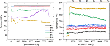
The monitored process parameters of the amidation and extraction are shown in Fig. 4 and S11 in the ESI.† The flow rate and pressure (F1–F6 and P1–P6, Fig. 3) were maintained constant throughout the operation, except for P5, which showed a slight pressure change. We speculated that a small precipitate was generated in the flow path of P5, which was flushed away at ∼5500 s. The temperature sensors T4 and T6 demonstrated a sharp increase in temperature at ∼400 s. This could be attributed to the fact that the inlets to T4 and T6 required ∼400 s to pump the reaction mixture to full volume as they were installed slightly downstream to the mixers for the activation and amidation reactions. Therefore, the heat generated from the reactions may have caused the sharp increase in the temperature at ∼400 s. Although the reason for the time-dependent continuous decrease in the temperature detected by T4 is unclear, the adhesion of some substances to the sensor might cause this phenomenon.
The obtained extract was concentrated (Fig. 5) in a thin-layer evaporator at 13 mL min−1, 30 hPa, 50 °C, and a rotor speed of 600 rpm. A lower rotor speed resulted in a low concentration rate, and a higher speed resulted in unstable rotation (see ESI†). Because the extraction solution contained a high water content (5.5 wt%), we installed a column filled with the drying agents, MgSO4 and molecular sieves 3A. This procedure afforded a concentrated sample with 0.14 wt% water, which fulfilled the requirement of <0.2 wt% water in the carboxylic acid solution. Finally, 94 mL of the concentrated solution of 93% purity (area%, determined by HPLC-UV analysis) was obtained. No evident side reactions were observed during this process.
We synthesized the tripeptide Fmoc-Ala-Phe-Phe-OH (6) from crude 4 using the same conditions and system as those described previously (Fig. 6), which afforded 670 mL of crude 6 of 79% purity (area% determined by HPLC-UV analysis) after 60 min of solution collection from the extraction unit. This solution was concentrated and purified to afford 9.3 g of pure tripeptide 6 in 64% isolated yield from 1. The sensor values suggested that the process proceeded steadily (see ESI† for details). To the best of our knowledge, this is the first report of automated liquid-phase continuous-flow peptide synthesis, including aqueous workup and concentration.
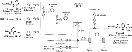 | ||
| Fig. 6 Synthesis and extraction of tripeptide 6. TMS-Phe-OTMS (3) was prepared from H-Phe-OH (2) and BSA in a batch reactor. | ||
NIR sensing of the reaction mixture in the amidation unit
The flow rate, pressure, and temperature sensors provide useful information for reaction monitoring but not on the chemical composition of the reaction solution. Hence, we used NIR spectroscopy20 for the in-line measurement of the concentration of the desired product. Ishigaki et al. reported that the NIR absorption band corresponding to the combination of amide A and II (amide A/II) modes is useful for the quantitative analysis of peptides.17a Hence, we monitored this NIR absorption.According to a previous study,17a the amide A/II band appears at approximately 4840 cm−1 in DMSO. Interestingly, the desired band appeared at 4910 cm−1 for a sample of compound 4 in a mixture of 2-MeTHF and MeCN (see ESI† for details). Before monitoring the flow reaction, we preliminary confirmed the overlaps of the peaks at ∼4910 cm−1. Consequently, the absorption of the reactant and reagents did not prevent the measurement of the peptide product (see ESI† for details).
Next, the progress of the reaction in the flow system was recorded via NIR spectroscopy. A flow cell was installed at the end of the amidation reaction tube. Spectra were recorded every 8 s during system operation. Before 380 s, only the solvent was passed through the reactor, and thus, the NIR absorption of the solvent was detected. From 380 to 1003 s, the absorption intensity of the product at ∼4910 cm−1 increased (Fig. 7, left). After 1003 s, the absorption intensity remained unchanged. The product yield was calculated from the NIR spectra using a calibration curve (Fig. 7, right). The desired product was obtained in high yield from 1003 s until the end of the operation (5941 s = ∼1.7 h). These results clearly show the potential of in-line NIR measurements for real-time tracking of the steady-state condition of a continuous-flow liquid-phase reaction. To the best of our knowledge, this is the first in-line NIR monitoring of peptide-bond formation.
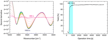 | ||
| Fig. 7 NIR spectra from 380 to 1003 s (left) and yield profile of the synthesis of 4 calculated from NIR measurement data (right). | ||
Conclusions
In this study, we developed a novel continuous-flow system comprising an amidation unit with a micro-flow reactor, an extraction unit with mixer-settlers, a concentration unit with a thin-layer evaporator, and a control unit. We successfully synthesized C-terminal-free peptides from a C- and N-terminal silylated amino acid and mixed carbonic anhydrides using our continuous-flow system. The reaction mixture from the amidation unit was continuously extracted to obtain 920 mL of the dipeptide 4 extract in 83 min of operation. The concentrate was obtained by processing the extract in the concentration unit and was directly used for the next amidation reaction to afford 9.3 g of the tripeptide 6. The steadiness of the flow system was continuously monitored by measuring the process parameters, namely the flow rate, pressure, and temperature. Furthermore, in-line monitoring of peptide synthesis using a NIR sensor was demonstrated. The product yield trend was successfully tracked every 8 s using the amide A/II band, which appeared at approximately 4910 cm−1. This research demonstrates a automated continuous-flow C-terminal free peptide synthesis with an integrated workup process and an adapted in-line PAT tool for the continuous manufacturing of peptide drugs. We expect that our strategy will contribute to the development of efficient manufacturing processes for peptides as well as other small- and middle-molecule drugs.Experimental
Procedure for the continuous-flow synthesis of a tripeptide using our developed system
Silylation (batch). BSA (24.6 mL, 100 mmol, 2.38 equiv.) was added to a suspension of H-L-Phe-OH (2) (8.29 g, 50.2 mmol, 1.19 equiv.) in MeCN (176 mL) at room temperature. The reaction mixture was stirred at 70 °C for 60 min and cooled to room temperature. The obtained solution of TMS-L-Phe-OTMS (3) was used directly for the next flow reaction.
Amidation and extraction (flow). At the first T-shaped mixer, a solution of Fmoc-L-Ala-OH (1) (0.200 M, 1.00 equiv.), Me2NBn (0.0200 M, 0.100 equiv.), and i-Pr2NEt (0.220 M, 1.10 equiv.) in 2-MeTHF (flow rate: 2.00 mL min−1) and a solution of IBCF (0.400 M, 1.20 equiv.) in MeCN (flow rate: 1.20 mL min−1) were mixed at 20 °C. The resultant mixture was passed through an activation reaction flow channel (residence time = 5 s) and mixed with a solution of TMS-L-Phe-OTMS (3) (0.240 M, 1.20 equiv.) in MeCN (flow rate: 2.00 mL min−1) at the second T-shaped mixer at 20 °C. The resultant mixture was then passed through an amidation reaction flow channel (residence time = 30 s) and was mixed at the cross mixer with 2-MeTHF (flow rate: 5.33 mL min−1) and aq. 0.08 M HCl + 5% NaCl (flow rate: 7.34 mL min−1) at room temperature. The resultant mixture was passed through the extraction flow channel (inner diameter: 1.59 mm, length: 3.00 m) and separated by the first settler. Then, the resultant organic phase solution and aq. 20% NaCl (flow rate: 6.17 mL min−1) were introduced into a T-shaped mixer at room temperature. The resultant mixture was passed through the extraction flow channel (inner diameter: 1.59 mm, length: 3.00 m) and separated by a second settler. After elution for 16 min to reach a steady state, the resultant organic phase solution was collected for 83 min at room temperature. The obtained crude solution of Fmoc-L-Ala-L-Phe-OH (4) (∼920 mL, water content: 5.5 wt%, purity: 96 area%) was directly used for the next concentration step.
Silylation (batch). BSA (19.5 mL, 79.6 mmol, 2.40 equiv.) was added to a suspension of H-L-Phe-OH (2) (6.58 g, 39.8 mmol, 1.20 equiv.) in MeCN (140 mL) at room temperature. The reaction mixture was stirred at 70 °C for 60 min and cooled to room temperature. The obtained solution of TMS-L-Phe-OTMS (3) was used for the subsequent flow reaction.
Amidation and extraction (flow). Me2NBn (499 μL, 3.32 mmol, 0.100 equiv.), i-Pr2NEt (6.21 mL, 36.5 mmol, 1.10 equiv.), and DMF (7.20 mL) were added to a crude solution of Fmoc-L-Ala-L-Phe-OH (4). 2-MeTHF was then added to achieve a total volume of 166 mL. This solution (water content: 0.098 wt%), a solution of IBCF, and a solution of TMS-L-Phe-OTMS (3) were introduced into the flow reactor. The operation procedure was the same as the procedure of the synthesis and extraction of Fmoc-L-Ala-L-Phe-OH (4). The resultant organic phase solution was collected after extraction for 60 min. The obtained crude solution of Fmoc-L-Ala-L-Phe-L-Phe-OH (6) (∼670 mL, purity: 79 area%) was dried over Na2SO4, filtered, and concentrated in vacuo. Purification by recrystallization from MeCN and column chromatography (Biotage Isolera One flash purification system, Sfär HC Duo 100 g, heptane:THF = 75
![[thin space (1/6-em)]](https://www.rsc.org/images/entities/char_2009.gif) :
:![[thin space (1/6-em)]](https://www.rsc.org/images/entities/char_2009.gif) 25 to 20
25 to 20![[thin space (1/6-em)]](https://www.rsc.org/images/entities/char_2009.gif) :
:![[thin space (1/6-em)]](https://www.rsc.org/images/entities/char_2009.gif) 80) afforded Fmoc-L-Ala-L-Phe-L-Phe-OH (6) (9.30 g, 20.3 mmol, 64%) as a white solid.
80) afforded Fmoc-L-Ala-L-Phe-L-Phe-OH (6) (9.30 g, 20.3 mmol, 64%) as a white solid.
mp: 203–205 °C; IR (ATR): 3298, 1710, 1690, 1650, 1539, 1452, 1262, 1085, 741, 699 cm−1; 1H NMR (600 MHz, DMSO-d6): δ 12.78 (brs, 1H), 8.26 (d, J = 7.8 Hz, 1H), 7.90–7.87 (m, 3H), 7.72–7.69 (m, 2H), 7.46 (d, J = 7.8 Hz, 1H), 7.42 (t, J = 7.2 Hz, 2H), 7.34–7.14 (m, 12H), 4.55–4.51 (m, 1H), 4.47–4.43 (m, 1H), 4.28–4.19 (m, 3H), 4.03–3.98 (m, 1H), 3.06 (dd, J = 5.4, 13.8 Hz, 1H), 3.00 (dd, J = 4.8, 13.8 Hz, 1H), 2.93 (dd, J = 8.4, 13.8 Hz, 1H), 2.78 (dd, J = 9.0, 13.8 Hz, 1H), 1.11 (d, J = 7.2 Hz, 3H); 13C NMR (151 MHz, DMSO-d6): δ 172.7, 172.1, 170.9, 155.6, 143.9, 143.8, 140.7, 137.5, 137.4, 129.3, 129.1, 128.2, 127.9, 127.6, 127.1, 126.5, 126.2, 125.3, 125.3, 120.1, 65.7, 53.5, 53.5, 50.1, 46.6, 37.5, 36.7, 18.2; HRMS (ESI-TOF): calcd. for [C36H35N3O6 + H]+ 606.2604, found 606.2606.
Continuous measurement of NIR spectra in the developed flow system
The reaction conditions are shown in section 6-1 in the ESI.† Sixteen scans of the spectra were obtained. Some parts of the processed spectra (380–1003 s, 5000–4800 cm−1) are shown in Fig. 7. These spectra were obtained by subtracting the second-derivative spectrum of the solvent from that of the reaction solution. The NIR spectrum of isolated Fmoc-L-Ala-L-Phe-OH (4) is shown in section 3-7 in the ESI.† These data were used to construct a calibration curve. We used a simple linear regression model. A plot of the concentration vs. the NIR peak height at 4914 cm−1 is shown in Fig. S21.† The yield of Fmoc-L-Ala-L-Phe-OH was calculated based on this calibration curve (Fig. 7).Author contributions
Yuma Otake: conceptualization, formal analysis, investigation, methodology, visualization, and writing – original draft. Kyohei Adachi and Yoshiaki Yamashita: data curation, investigation, and validation. Natsumi Iwanaga and Taiki Shamoto: investigation. Hirokatsu Sunakawa: resources and software. Jun-ichi Ogawa: formal analysis and investigation. Atsushi Ito and Daisuke Kubo: conceptualization and project administration. Yutaka Kobayashi: conceptualization and resources. Keiichi Masuya and Shinichiro Fuse: conceptualization and supervision. Hidenosuke Itoh: conceptualization, funding acquisition, and supervision. All authors: writing – review & editing.Conflicts of interest
There are no conflicts of interest to declare.Acknowledgements
This work was supported by JST-Mirai Program Japan (Grant Number JPMJMI18G7). The authors would like to thank Yusuke Hattori and Kodai Murayama for the insightful discussions, Takeshi Sawada for the optical system assembly, and Yusuke Imamura for the temperature sensor assembly.Notes and references
- M. Muttenthaler, G. F. King, D. J. Adams and P. F. Alewood, Nat. Rev. Drug Discovery, 2021, 20, 309 CrossRef CAS PubMed.
- A. Isidro-Llobet, M. N. Kenworthy, S. Mukherjee, M. E. Kopach, K. Wegner, F. Gallou, A. G. Smith and F. Roschangar, J. Org. Chem., 2019, 84, 4615 CrossRef CAS PubMed.
- J. H. Rasmussen, Bioorg. Med. Chem., 2018, 26, 2914 CrossRef CAS PubMed.
- The first chemical peptide synthesis using C- and N-terminal-free glycine, see: (a) T. Curtius, J. Prakt. Chem., 1881, 24, 239 CrossRef ; Peptide synthesis via coupling between mixed anhydrides and C- and N-terminal-free amino acids or peptides, see; (b) T. Wieland and R. Sehring, Liebigs Ann. Chem., 1950, 569, 122 CrossRef CAS; (c) J. R. Vaughan and R. L. Osato, J. Am. Chem. Soc., 1952, 74, 676 CrossRef CAS; (d) S. Fuse, K. Masuda, Y. Otake and H. Nakamura, Chem. – Eur. J., 2019, 25, 15091 CrossRef CAS PubMed and references therein.
- F. Bambino, R. T. C. Brownlee and F. C. K. Chiu, Tetrahedron Lett., 1991, 32, 3407 CrossRef CAS.
- (a) S. J. Tantry and V. V. S. Babu, Indian J. Chem., 2004, 43B, 1282 CAS; (b) Y. Huang and W.-H. Feng, Chin. Chem. Lett., 2016, 27, 357 CrossRef CAS; (c) H. Kurasaki, A. Nagaya, Y. Kobayashi, A. Matsuda, M. Matsumoto, K. Morimoto, T. Taguri, H. Takeuchi, M. Handa, D. R. Cary, N. Nishizawa and K. Masuya, Org. Lett., 2020, 22, 8039 CrossRef CAS PubMed; (d) Nissan Chemical Corporation, US Pat., 20220204550A1, 2022 Search PubMed.
- (a) J.-I. Yoshida, A. Nagaki and T. Yamada, Chem. – Eur. J., 2008, 14, 7450 CrossRef CAS PubMed; (b) C. Jiménez-González, P. Poechlauer, Q. B. Broxterman, B.-S. Yang, D. A. Ende, J. Baird, C. Bertsch, R. E. Hannah, P. Dell'Orco, H. Noorman, S. Yee, R. Reintjens, A. Wells, V. Massonneau and J. Manley, Org. Process Res. Dev., 2011, 15, 900 CrossRef; (c) M. Movsisyan, E. I. P. Delbeke, J. K. E. T. Berton, C. Battilocchio, S. V. Ley and C. V. Stevens, Chem. Soc. Rev., 2016, 45, 4892 RSC; (d) M. B. Plutschack, B. Pieber, K. Gilmore and P. H. Seeberger, Chem. Rev., 2017, 117, 11796 CrossRef CAS PubMed; (e) N. Kockmann, P. Thenée, C. Fleischer-Trebes, G. Laudadio and T. Noël, React. Chem. Eng., 2017, 2, 258 RSC; (f) D. Cantillo and C. O. Kappe, React. Chem. Eng., 2017, 2, 7 RSC; (g) R. Gérardy, N. Emmanuel, T. Toupy, V.-E. Kassin, N. N. Tshibalonza, M. Schmitz and J.-C. M. Monbaliu, Eur. J. Org. Chem., 2018, 2018, 2301 CrossRef; (h) M. Guidi, P. H. Seeberger and K. Gilmore, Chem. Soc. Rev., 2020, 49, 8910 RSC.
- (a) S. Ramesh, P. Cherkupally, B. G. de la Torre, T. Govender, H. G. Kruger and F. Albericio, Amino Acids, 2014, 46, 2091 CrossRef CAS PubMed; (b) N. Ahmed, Chem. Biol. Drug Des., 2018, 91, 647 CrossRef CAS PubMed; (c) S. Fuse, Y. Otake and H. Nakamura, Chem. – Asian J., 2018, 13, 3818 CrossRef CAS PubMed; (d) C. P. Gordon, Org. Biomol. Chem., 2018, 16, 180 RSC; (e) K. Schiefelbein and N. Hartrampf, Chimia, 2021, 75, 480 CrossRef CAS PubMed; (f) H. Masui and S. Fuse, Org. Process Res. Dev., 2022, 26, 1751 CrossRef CAS.
- M. Trobe and M. D. Burke, Angew. Chem., Int. Ed., 2018, 57, 4192 CrossRef CAS PubMed.
- C. P. Breen, A. M. K. Nambiar, T. F. Jamison and K. F. Jensen, Trends Chem., 2021, 3, 373 CrossRef.
- N. Hartrampf, A. Saebi, M. Poskus, Z. P. Gates, A. J. Callahan, A. E. Cowfer, S. Hanna, S. Antilla, C. K. Schissel, A. J. Quartararo, X. Ye, A. J. Mijalis, M. D. Simon, A. Loas, S. Liu, C. Jessen, T. E. Nielsen and B. L. Pentelute, Science, 2020, 368, 980 CrossRef CAS PubMed.
- U.S. Food and Drug Administration, Guidance for Industry, PAT: A Framework for Innovative Pharmaceutical Development, Manufacturing, and Quality Assurance, https://www.fda.gov/downloads/drugs/guidances/ucm070305.pdf, (accessed Sep 2nd, 2022).
- (a) G. A. Price, D. Mallik and M. G. Organ, J. Flow Chem., 2017, 7, 82 CrossRef CAS; (b) M. A. Morin, W. Zhang, D. Mallik and M. G. Organ, Angew. Chem., 2021, 60, 20606 CrossRef CAS PubMed; (c) D. Hebrault, A. J. Rein and B. Wittkamp, ACS Sustainable Chem. Eng., 2022, 10, 5072 CrossRef CAS.
- J. Li, H. Šimek, D. Ilioae, N. Jung, S. Bräse, H. Zappe, R. Dittmeyer and B. P. Ladewig, React. Chem. Eng., 2021, 6, 1497 RSC.
- (a) E. T. Sletten, M. Nuño, D. Guthrie and P. H. Seeberger, Chem. Commun., 2019, 55, 14598 RSC; (b) S. Mohapatra, N. Hartrampf, M. Poskus, A. Loas, R. Gómez-Bombarelli and B. L. Pentelute, ACS Cent. Sci., 2020, 6, 2277 CrossRef CAS PubMed.
- NIR spectroscopy is a spectroscopic technique in the region of 12500–4000 cm−1. For previous reports on continuous-flow synthesis, see: (a) W. Ferstl, T. Klahn, W. Schweikert, G. Billeb, M. Schwarzer and S. Loebbecke, Chem. Eng. Technol., 2007, 30, 370 CrossRef CAS; (b) A. E. Cervera-Padrell, J. P. Nielsen, M. Jønch Pedersen, K. Müller Christensen, A. R. Mortensen, T. Skovby, K. Dam-Johansen, S. Kiil and K. V. Gernaey, Org. Process Res. Dev., 2012, 16, 901 CrossRef CAS; (c) A. Mitic, A. E. Cervera-Padrell, A. R. Mortensen, T. Skovby, K. Dam-Johansen, I. Javakhishvili, S. Hvilsted and K. V. Gernaey, Org. Process Res. Dev., 2016, 20, 395 CrossRef CAS; (d) R. Galaverna, R. L. Ribessi, J. J. R. Rohwedder and J. C. Pastre, Org. Process Res. Dev., 2018, 22, 780 CrossRef CAS.
- (a) M. Ishigaki, A. Ito, R. Hara, S.-I. Miyazaki, K. Murayama, K. Yoshikiyo, T. Yamamoto and Y. Ozaki, Anal. Chem., 2021, 93, 2758 CrossRef CAS PubMed; (b) M. Ishigaki, A. Ito, R. Hara, S.-I. Miyazaki, K. Murayama, S. Tusji, M. Inomata, K. Yoshikiyo, T. Yamamoto and Y. Ozaki, Analyst, 2022, 147, 3634 RSC.
- Yokogawa Electric Corporation, US Pat., 20210299628A1, 2021 Search PubMed.
- Y. Otake, Y. Shibata, Y. Hayashi, S. Kawauchi, H. Nakamura and S. Fuse, Angew. Chem., Int. Ed., 2020, 59, 12925 CrossRef CAS PubMed.
- A feature of NIR spectroscopy is the lower molar absorption coefficient of organic compounds than IR. Because of this feature, we were able to collect transmittance NIR spectra. This implies that the absorbance of transmittance spectra can be controlled to be at the adequate level by the optical path length (for details: Y. Hattori, Anal. Sci., 2022, 38, 1455.). We can also use selected NIR for this study.
Footnote |
| † Electronic supplementary information (ESI) available. See DOI: https://doi.org/10.1039/d2re00453d |
| This journal is © The Royal Society of Chemistry 2023 |

