 Open Access Article
CO2 electro-reduction reaction via a two-dimensional TM@TAP single-atom catalyst†
Xiaolin Wang *a,
Qing Zhangb,
Shenghai Zhang
 a,
Mengyu Wena and
Shaowei Jinc
aSchool of Chemistry and Chemical Engineering, Ankang Research Centre of New Nano-materials Science and Technology, Qinba Chinese Medicine Resources R&D Center, Ankang University, Ankang 725000, China. E-mail: wangxlchem@foxmail.com
bDepartment of Materials Chemistry, Huzhou University, Huzhou, 313000, China
cNational Supercomputing Center of China in ShenZhen, Shenzhen, 518000, China
First published on 4th December 2023
Abstract
In this study, the possibility of using TM atom anchored monolayer TAP as a class of electrocatalysts (TM@TAP, TM = 3d and 4d transition metal) toward carbon dioxide reduction reaction (CO2RR) was systematically investigated using first-principles calculations. During screening potential catalysts, the possibility that H and OH block the active site was considered. Then, the reaction mechanisms of screened catalysts were explored in detail. Interestingly, the different catalysts demonstrated different selectivities. Our results demonstrate that Cr@TAP, Zn@TAP, Mo@TAP, and Cd@TAP are selective toward the HCOOH product with a limiting potential in the range of −0.33 to −0.71 V. Mn@TAP and Rh@TAP promote CO production. The reduction products of Fe@TAP and Co@TAP were CH3OH and HCHO, respectively. Tc@TAP and Ru@TAP can catalyze CO2 to yield the deep reduction product, i.e. CH4. Among these catalysts, Cr@TAP and Rh@TAP are highly active due to their lower limiting potentials of −0.33 V and −0.28 V, respectively, and Fe@TAP can promote the production of the desired CH3OH with a limiting potential of −0.51 V, which allow them to be promising electrocatalysts for the CO2RR. We hope that our study will provide some insights into the rational design of electrocatalysts and useful guidance for experimental researchers.
1. Introduction
The greenhouse effect caused by the burning of fossil fuels is a great threat to mankind.1,2 The utilization of carbon dioxide resources is one of the most challenging and effective ways to solve the problem.3,4 Among the many methods for CO2 resource utilization, the electrocatalytic carbon dioxide reduction reaction (CO2RR) has been identified as one of the most promising methods and has gained considerable interest due to mild reaction conditions (operated at room temperature and ambient pressure) and the reaction products of the reduction process readily controlled by the applied potential.5–8 However, poor selectivity, low efficiency, and large overpotential limit the development of CO2RR.9–13 Therefore, it is quite crucial to discover highly efficient electrocatalysts for CO2RR.In recent years, single-atom catalysts (SACs) have exhibited outstanding activity, high stability, exceptional selectivity, maximum atom utilization, and excellent catalytic performance in many catalytic reactions owing to their unique electronic and structural properties and have, therefore, become a hot spot in the field of catalyst research.14–22 The selection of substrate plays an important role in determining the activity, selectivity, and stability of SACs. Compared with three-dimensional materials, two-dimensional (2D) materials possess high surface areas and more low-coordinated active sites,23–25 which make them very attractive substrate materials. According to the current reports on SACs for the CO2RR, catalysts with outstanding selectivity, high catalytic efficiency, and good stability are still scarce.26–29 Hence, developing and designing highly efficient and stable SACs based on 2D materials is urgently desired for CO2RR.
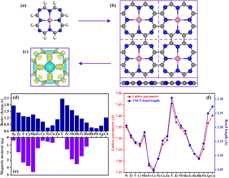
In 2004, Kobayashi et al. synthesized tetraazaporphyrins, phthalocyanines, naphthalocyanines, and anthracocyanines and studied their spectroscopic properties, electrochemical properties, and molecular orbitals, and the results showed that the stability of the compound decreases as the molecular size increases.30 In 2011, Abel et al. successfully prepared the polymeric Fe-phthalocyanine monolayer, implying that it is feasible to create a wide range of organometallic polymer films with adjustable composition, structure, and performance.31 In 2014, Wiengarten et al. reported a covalent dehydrogenative coupling mechanism yielding covalent porphine aggregates directly on Ag(111) support, which showed prospects for the exploration of extended oligomers with tailored chemical and physical properties.32 Considering that the stability determines whether the catalyst can actually be applied in practical applications, we aimed to design a class of catalysts with high stability. Inspired by the above experimental methods and conclusions, we chose the core structure of tetraazaporphyrins as the substrate, i.e., the chelation skeleton was composed of 8 N atoms and 8 C atoms, and the transition metal (including 3d and 4d series) atoms were embedded in the substrate to construct the catalysts (as shown in Fig. 1). For convenience, the substrate and catalysts were named TAP and TM@TAP, respectively.
Herein, based on first-principles calculations, the potential of TM@TAP as electrocatalysts for the CO2RR is systematically investigated. In addition to the binding energy (Eb) and cohesive energy (Ec), the results of ab initio molecular dynamics (AIMD) simulations were employed to evaluate the stability of the catalyst. The selectivity of the catalyst was investigated in order to screen more promising candidates. The possible reaction pathways of screened candidates have been comprehensively explored. The results indicate that Cr@TAP, Rh@TAP, and Fe@TAP are potential catalysts for promoting HCOOH, CO, and CH3OH production, respectively, in the electrochemical CO2RR.
2. Computational methods
The spin-polarized density functional theory (DFT), implemented in the Vienna Ab initio Simulation Package (VASP),33 was used for all computations. In order to treat the interactions between electrons, the revised Perdew–Burke–Ernzerhof (RPBE)34,35 exchange–correlation functional within the generalized gradient approximation (GGA) was employed. The projector augmented wave (PAW) pseudopotential36,37 was adopted to describe the core–valence interactions. The van der Waals (vdW) interactions were considered by the DFT-D3 method.38 The kinetic energy cutoff for the plane wave basis was set to 500 eV. The Brillouin zones were sampled by a Γ-centered Monkhorst–Pack mesh.39 The k-points were set to 7 × 7 × 1 for geometry optimization and 25 × 25 × 1 for electronic structure computations. The convergence threshold was 10−5 eV and 0.01 eV Å−1 for the total energy and force on each atom, respectively. A Gaussian smearing with a width of kBT = 0.05 eV was used during all computations. To avoid the interactions between periodic images, the thickness of the vacuum layer along the z direction was set to 15 Å. The energy of gas-phase molecules was calculated in a 15 × 15 × 15 Å unit cell with Γ point sampling.Based on the computational hydrogen electrode (CHE) model,40 the Gibbs free energy change (ΔG) for each elementary step in the overall reaction is denoted as follows:
| ΔG = ΔE + ΔZPE + Δ∫CpdT − TΔS + ΔGU + ΔGpH |
![[thin space (1/6-em)]](https://www.rsc.org/images/entities/char_2009.gif) 10 × pH, and the pH was set to 0 for the strong acidic medium in this work. ΔZPE, TΔS, and ∫CpdT can be acquired from the vibrational frequency calculation, in which the catalyst itself is fixed and only the frequency of adsorbed species is calculated. However, ΔZPE, TΔS, and ∫CpdT of the gas-phase molecules were taken from the NIST database.41 The elementary step involving proton–electron pair transfer with the maximum free energy change (ΔGmax) is defined as the potential-determining step (PDS), and the limiting potential (UL) is calculated as UL = −ΔGmax/e. The thermal stabilities of the catalysts for practical applications were evaluated by ab initio molecular dynamics (AIMD) simulations with NVT ensembles under 500 K for 10 ps with a time step of 2 fs. The temperature was controlled using the Nosé–Hoover thermostat method.42 A 3 × 3 × 1 supercell containing 153 atoms was used for the simulations without any symmetry constraints. More details are shown in the ESI.†
10 × pH, and the pH was set to 0 for the strong acidic medium in this work. ΔZPE, TΔS, and ∫CpdT can be acquired from the vibrational frequency calculation, in which the catalyst itself is fixed and only the frequency of adsorbed species is calculated. However, ΔZPE, TΔS, and ∫CpdT of the gas-phase molecules were taken from the NIST database.41 The elementary step involving proton–electron pair transfer with the maximum free energy change (ΔGmax) is defined as the potential-determining step (PDS), and the limiting potential (UL) is calculated as UL = −ΔGmax/e. The thermal stabilities of the catalysts for practical applications were evaluated by ab initio molecular dynamics (AIMD) simulations with NVT ensembles under 500 K for 10 ps with a time step of 2 fs. The temperature was controlled using the Nosé–Hoover thermostat method.42 A 3 × 3 × 1 supercell containing 153 atoms was used for the simulations without any symmetry constraints. More details are shown in the ESI.†
3. Results and discussion
3.1 Structures of TM@TAP
Fig. 1a and b show a single TM@TAP molecule and the optimized structure of the TM@TAP monolayer in a (2 × 2) supercell, respectively. The two-dimensional TM@TAP monolayer (Fig. 1b) is expected to be prepared by the dehydrogenative coupling reaction of a single TM@TAP molecule (Fig. 1a). As shown in the picture, the unit cell of TM@TAP contains 8 carbon atoms, 8 nitrogen atoms and 1 transition metal atom bound to four nitrogen atoms. In this work, the transition metals refer to the first and second series of transition metals, thus corresponding to a total of 20 TM@TAP. To visually understand the bonding mechanism of the transition metal atom on the substrate, the charge density differences of Sc@TAP are mapped out in Fig. 1c, showing that the electrons of the metal atom decrease and the electrons of atoms of TAP accumulate. The Bader charge analysis43 was also performed to gain further information regarding the charge distribution and charge transfer between the metal atom and substrate, and the corresponding data are depicted in Fig. 1d. All center metal atoms present a positive charge, indicating that electrons were transferred from the metal atom to the substrate, resulting in good bonding between the metal atom and substrate. The magnetic moments, lattice parameters, and TM–N bond lengths of TM@TAP are shown in Fig. 1e and f. As shown in Fig. 1e, all materials (except TM = Zn, Y, Rh, Pd, Cd) have magnetic properties. Among these materials with magnetic properties, the magnetic moment of the Mn@TAP monolayer is the largest with 4.59 μB, while the magnetic moment of Ag@TAP is the smallest featuring 0.02 μB. For 20 TM@TAP, the lattice parameters and TM–N bond lengths are in the range from 7.164 to 7.455 Å, and 2.046 to 2.304 Å, respectively. Interestingly, one can see from Fig. 1f that the lattice parameters increase with the increase in TM–N bond length, indicating that the changes in lattice parameters are consistent with the changes in the TM–N bond length.3.2 Stability of catalysts
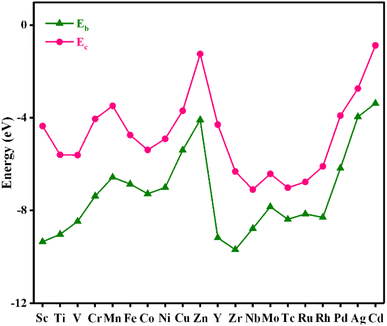
Stability plays an important role in evaluating the performance of catalysts in practical applications. To assess the stability of the material, the binding energy (Eb) between the metal atom and substrate and the cohesive energy (Ec) of metal atoms were calculated, and the results are shown in Fig. 2 and Table S2.† The more negative the Eb, the stronger the binding between the metal atom and substrate. If Ec is more negative than Eb, the metal atom in the catalyst is likely to aggregate into large particles, implying that the catalyst is unstable. As shown in Fig. 2, Eb is below Ec for all the catalysts, indicating that these catalysts are stable.AIMD simulations were performed to verify the thermal stabilities of the catalysts with NVT ensembles at 500 K for 10 ps with a time step of 2 fs. The variation in the temperature and total energy over time and the geometry structures before and after simulations are shown in Fig. 3. Although there were some slight oscillations in the temperature and total energy, and some distortion in the final geometry, the structural integrity of the catalysts was maintained well. Moreover, the transition metal atoms were firmly anchored on the substrate without migration and aggregation into particles during the simulated annealing. All these results demonstrate their good thermal stabilities and allow their long-term utilization.
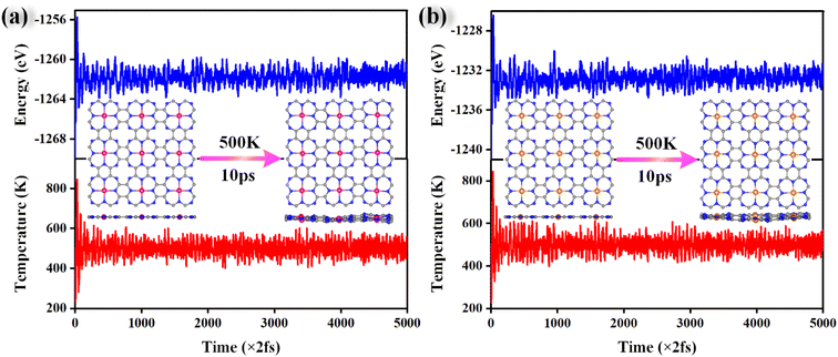 | ||
| Fig. 3 The variations in the total energy and temperature during AIMD simulations of Cr@TAP (a) and Rh@TAP (b) at 500 K for 10 ps with a time step of 2 fs. | ||
3.3 Selectivity of catalysts
Selectivity plays a critical role in the practical application of TM@TAP as electrocatalysts for the CO2RR. The hydrogen evolution reaction (HER) and water oxidation reaction are major competing reactions for the CO2RR and will be discussed in the following sections.The intermediate of the first protonation step for CO2RR is either *COOH or *OCHO, and the first step of the HER gives the *H intermediate. If another proton–electron pair approaches *H, H2 will be produced, which is undesired and unfavorable for the CO2RR. The free energy changes for *COOH, *OCHO, and *H were calculated, and the related data are shown in Fig. 4a. The reaction with the lower free energy change is considered to be more favorable and selective.44,45 Above the dashed line in Fig. 4a, the ΔG of *H is more negative than that of *COOH or *OCHO, demonstrating that the HER is more favorable, while below the dashed line, the CO2RR is more selective. As can be seen in the picture, only *COOH for Tc and Cd and *OCHO for Fe, Co, Tc, Ru, and Rh are located above the dashed line, which is unfavorable for the CO2RR. Most of the catalysts are located below the dashed line, indicating their good suppressing effect on the HER. For a catalyst with ΔG of both *OCHO and *COOH below the line, the ΔG of *OCHO is more negative than that of *COOH, suggesting that the formation of *OCHO is more preferred than *COOH. Given that our goal is to find potential catalysts with low overpotential, Ni, Cu, Pd, and Ag were excluded in the following study due to their high free energy barriers for the first protonation step for the CO2RR. Accordingly, the remaining 16 materials entered the subsequent study.
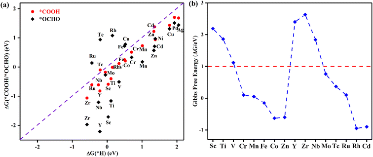 | ||
| Fig. 4 (a) The Gibbs free energy changes for the first protonation step for the CO2RR and HER. (b) Gibbs free energy change corresponding to OH elimination becoming H2O on TM@TAP. | ||
In addition to H possibly blocking the active site, the possibility of OH poisoning of the active site was also considered. Brief excursions to positive potential may result in H2O dissociation, followed by subsequent OH poisoning of the active site, which might compete with the CO2RR and remarkably influence the Faradaic efficiency.44,46–48 Therefore, the free energy changes of OH elimination for 16 materials were calculated to estimate whether the active site would be poisoned, and the results are shown in Fig. 4b. ΔG of OH elimination for Sc, Ti, V, Y, Zr, and Nb are greater than 1 eV, which means that OH will poison the active sites of these catalysts because they require the more negative applied potential to remove OH from the active sites. According to the above analysis, the six abovementioned materials were ruled out. We will focus on the other ten catalysts (TM = Cr, Mn, Fe, Co, Zn, Mo, Tc, Ru, Rh, and Cd) in the following study.
3.4 Reaction mechanism
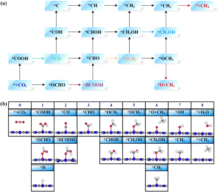
Next, the possible reaction pathways of the screened ten catalysts are considered and calculated. In this work, only the C1 product is considered because it is less possible to form the C2 product by the coupling of C1 intermediates for the single active site. The possible reaction pathways for the CO2RR are illustrated in Fig. 5, from which one can observe that those C1 products include two-electron reduction products (CO and HCOOH), a four-electron reduction product (HCHO), a six-electron reduction product (CH3OH) and an eight-electron reduction product (CH4). The adsorption energy of the key product (such as CO, or HCHO) plays an important role in determining whether the key product will desorb or continue to be reduced to other species. The adsorption energies of the key products for the ten selected catalysts are listed in Table S3.† The projected crystal orbital Hamilton population (pCOHP)49–52 between the TM atom and the key atom of the product was calculated to analyze and confirm whether the product is capable of desorption, and the corresponding data are shown in Fig. S2.† When the antibonding orbitals are below the Fermi level or the bonding states are above the Fermi level, the adsorption strength will be weakened. The integrated-crystal orbital Hamilton population (ICOHP) analysis was performed and is shown in Fig. S2.† The more positive the ICOHP, the weaker the binding strength.The reaction mechanisms for the CO2RR on the screened SACs were calculated, and the corresponding free energy profiles are shown in Fig. 6. The thermal corrections of the reaction intermediates on the ten catalysts TM@TAP are listed in Table S5.† Fig. 6a shows that the CO2 is hydrogenated to generate *OCHO or *COOH on Cr@TAP, and then *OCHO will be reduced to *HCOOH, or *COOH will be protonated into *CO and H2O. If the adsorption energies of HCOOH and CO on the catalyst are strong, *HCOOH or *CO will be further reduced to the other intermediates. For Cr@TAP, the adsorption energies of CO and HCOOH are −0.28 and −0.49 eV, indicating that the adsorption energies are weak and will cause CO and HCOOH to detach from the surface as the products. The free energy change for *OCHO formation is smaller than that for *COOH formation on Cr@TAP, suggesting that in the first protonation step, CO2 prefers to be reduced to the *OCHO intermediate. The generation of *OCHO is uphill in free energy by 0.33 eV, and subsequent conversion to HCOOH is exothermic. For the whole process, the formation of *OCHO is the potential-determining step with the ΔGmax of 0.33 eV, and the main product is HCOOH. As shown in Fig. S2,† the spin-up and spin-down ICOHP values for HCOOH on Cr@TAP are −0.06 and −0.26, indicating that the bonding strength between HCOOH and Cr@TAP is weak and HCOOH will desorb from the catalyst. The mechanisms of Zn@TAP, Mo@TAP and Cd@TAP are similar to that of Cr@TAP, i.e., the formation of *OCHO is more favorable than that of *COOH. Moreover, *OCHO continues to be reduced to HCOOH, which will detach from the surface as the final product due to weak adsorption energy and bonding strength (Table S3 and Fig. S2†). Given that the free energy changes for *COOH formation for Zn@TAP and Cd@TAP are larger than 1 eV, the subsequent hydrogenation step of *COOH is not considered. The generation of *OCHO is the PDS for Zn@TAP and Cd@TAP, with free energy changes of 0.57 and 0.71 eV, respectively. For Mo@TAP, the formation of *COOH and *OCHO have downhill free energies of −0.18 and −0.27 eV, respectively. If the reaction continues along the *OCHO pathway, *OCHO will be reduced to HCOOH with the free energy change of 0.50 eV. Along the pathway with the *COOH intermediate, *COOH is protonated to yield *CO and H2O. The adsorption energies of HCOOH and CO are −0.39 and −1.72 eV, respectively, implying that HCOOH will desorb from the catalyst as the product and CO will continue to react as the intermediate. *CO is then protonated to *CHO with the uphill free energy of 0.96 eV, which is larger than the free energy input of 0.50 eV required for HCOOH formation, rendering HCOOH the most likely final product. Fig. 6b shows that the *COOH and *OCHO formation for Mn@TAP have the uphill free energies of 0.73 and 0.18 eV, respectively. Subsequently, the *COOH reduction to *CO and *OCHO hydrogenation into *HCOOH are both exothermic. CO possesses a weak adsorption energy of −0.36 eV, implying that CO detaches from the surface as the product. However, the adsorption energy of HCOOH is moderate, and thus *HCOOH continues to be hydrogenated into *CHO with an energy demand of 0.81 eV. Then, *CHO is protonated to generate HCHO, which will desorb as the product due to its weak adsorption energy. The above discussion demonstrates that the primary path on Mn@TAP is the formation of CO with ΔGmax of 0.73 eV, and the minor pathway is the formation of HCHO with ΔGmax of 0.81 eV. Next, we will discuss the reaction mechanisms of the five remaining catalysts (TM = Fe, Co, Tc, Ru, Rh). In the discussion of selectivity, the free energy changes of *H are all more negative than those of *OCHO for the five catalysts, which means that the HER is more favorable. Consequently, only the paths of further reaction along *COOH are considered. The protonation of *COOH can lead to the formation of *CO and H2O. CO is the final product of the CO2RR for Rh@TAP due to its weak adsorption energy, whereas *CO will be further reduced to other intermediates for the four remaining catalysts (TM = Fe, Co, Tc, Ru) because of the strong adsorption energy between CO and the catalysts. Compared to the formation of *COH, *CO on the four catalysts is favorably hydrogenated to form *CHO due to the smaller uphill free energy. In the subsequent step, the *CHO will be protonated to form either *CHOH or *OCH2. The *CHO on Co@TAP prefers to be reduced to OCH2, i.e., HCHO, which will desorb from the surface due to the weak adsorption energy of −0.37 eV. For Fe@TAP, Tc@TAP, and Ru@TAP, *CHOH is more favorable than *OCH2 because of its smaller required free energy input. The further reduction of *CHOH gives either *CH and H2O, or *CH2OH, and *CH2OH is the preferred intermediate. Subsequently, *CH2OH will be hydrogenated into either *CH3OH or *CH2 and H2O. The free energy change for *CH3OH formation on Fe@TAP is downhill, and CH3OH is the final product of the CO2RR due to its weak adsorption energy. For Tc@TAP and Ru@TAP, the free energy change for *CH2 and H2O formation is smaller than that for *CH3OH generation, implying that the formation of *CH2 is more favorable. The two proton–electron pairs will then continuously attack *CH2 to yield *CH3 and *CH4, and finally CH4 will detach from the catalysts as the product. The picture shows that the formation of CO and HCHO is the PDS for Rh@TAP and Co@TAP with the ΔGmax of 0.28 and 0.36 eV, respectively, and the generation of *CHO is the PDS for Fe@TAP, Tc@TAP and Ru@TAP, with the ΔGmax of 0.51, 1.04, and 0.65 eV, respectively.
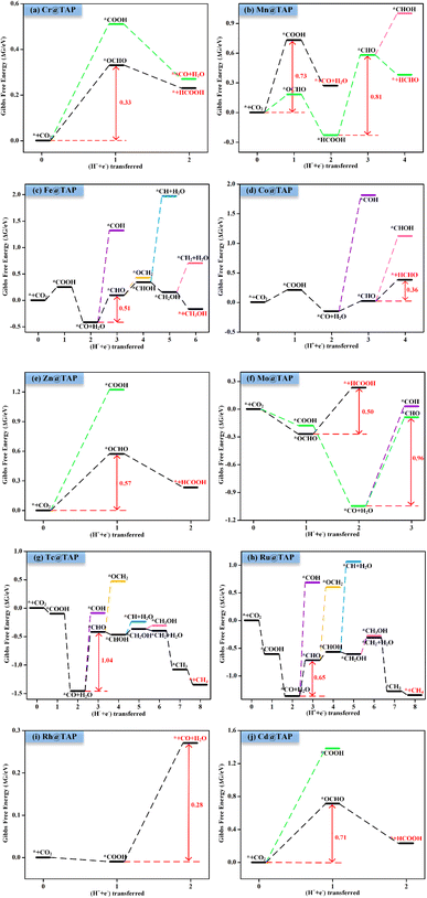 | ||
| Fig. 6 Gibbs free energy profiles for CO2RR on (a) Cr@TAP, (b) Mn@TAP, (c) Fe@TAP, (d) Co@TAP, (e) Zn@TAP, (f) Mo@TAP, (g) Tc@TAP, (h) Ru@TAP, (i) Rh@TAP, and (j) Cd@TAP at 0 V. | ||
3.5 Analysis of the underlying mechanism of catalytic performance
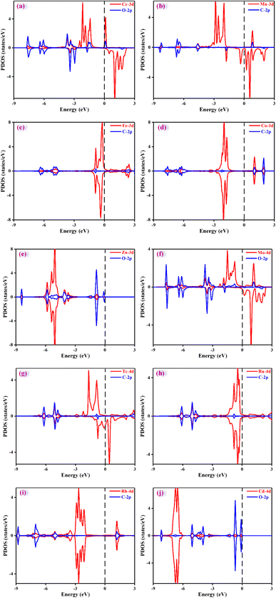
It is crucial to find a descriptor to understand the origin of catalytic activity. From previous reported work in literature,53–56 the adsorption energy of a key reaction intermediate or magnetic moment can be used as a descriptor to reflect the catalytic performance. The binding energies of key intermediates and magnetic moments of the ten catalysts are listed in Table S6.† Unfortunately, there is no obvious correlation between magnetic moment and catalytic activity. After much effort, these adsorption energies could not be used as descriptors to characterize the activities of ten catalysts. This may be because the products and the PDS of the ten catalysts are different. However, it was found that the adsorption energy of a key intermediate can characterize the activity of the catalysts with the same PDS. For example, the catalytic product of Cr@TAP, Zn@TAP, and Cd@TAP is HCOOH, and the PDS for the three catalysts is the formation of *OCHO. The adsorption energy of *OCHO decreases in the order of Cd@TAP (0.35 eV) > Zn@TAP (0.18 eV) > Cr@TAP (−0.17 eV), and the ΔGmax decreases in the order of Cd@TAP (0.71 eV) > Zn@TAP (0.57 eV) > Cr@TAP (0.33 eV). Therefore, the adsorption energy of *OCHO can be used as a descriptor to characterize the activity of TM@TAP (TM = Cr, Zn, Cd). For Fe@TAP, Tc@TAP, and Ru@TAP, the product of Fe@TAP is CH3OH, and the products of Tc@TAP and Ru@TAP are CH4. Although their products are different, their PDS is *CO → *CHO. The adsorption energy of *CO is ranked as follows: Tc@TAP (−2.16 eV) < Ru@TAP (−2.08 eV) < Fe@TAP (−1.12 eV). If the binding energy of *CO is stronger, the generation of *CHO from *CO will need a higher free energy input. The ΔGmax increases in the order of Fe@TAP (0.51 eV) < Ru@TAP (0.65 eV) < Tc@TAP (1.04 eV). Hence, the strength of the *CO adsorption energy can be used to reflect the activity of TM@TAP (TM = Fe, Ru, Tc).As mentioned above, the strength of the interaction between the intermediate and catalyst can affect the free energy change for the protonation step, thereby affecting the performance of the catalyst. To understand the electronic properties of the catalysts, the projected density of states (PDOS) for the key intermediates were plotted as shown in Fig. 7. The four catalysts (TM = Cr, Zn, Mo, Cd) can reduce CO2 to HCOOH, and thus the PDOS of *OCHO were calculated and mapped out. The d states of the Cr atom and p states of the O atoms of *OCHO have significant hybridizations, implying strong interactions between the catalyst and adsorbed species, whereas the overlap between the d states of the Cd atom and p states of the O atom for *OCHO is small. This could be why Cr@TAP and Cd@TAP respectively have the highest and lowest catalytic activities among the four catalysts. Similarly, the PDOS of *COOH for Mn@TAP and Rh@TAP were computed since the two catalysts can catalyze CO2 into CO. The overlap between the d states of the TM atom and p states of the C atom of *COOH for Rh@TAP is more obvious than that for Mn@TAP, indicating stronger binding between Rh@TAP and COOH, which may be responsible for its higher catalytic activity.
4. Conclusion
In this work, we systematically investigated the possibility of the TM@TAP monolayer (TM = 3d and 4d transition metal atoms) as an electrocatalyst for the conversion of CO2 into valuable fuels by applying first-principles calculations. The binding energy is more negative than the cohesive energy for all materials, implying that these materials are stable. The AIMD simulation results further verified the thermal stabilities of the catalysts, which pave the way towards practical applications. The side reactions of the HER and water oxidation were considered for selecting the more promising catalyst candidates. The CO2RR mechanisms of the screened catalyst candidates were then explored. The results show that the different catalysts had different selectivities. The product of Cr@TAP, Zn@TAP, Mo@TAP, and Cd@TAP is HCOOH, where the limiting potential of Cr@TAP is −0.33 V and the limiting potentials of the other materials were in the range of −0.50 to −0.71 V. Mn@TAP and Rh@TAP can catalyze CO2 to produce CO with a limiting potential of −0.73 and −0.28 V, respectively. The reduction products of Fe@TAP and Co@TAP were CH3OH and HCHO with the limiting potentials of −0.51 and −0.36 V, respectively. Tc@TAP and Ru@TAP can reduce CO2 to CH4 with limiting potentials of −1.04 and −0.65 V, respectively. Among these catalysts, Cr@TAP and Rh@TAP may possess promising application prospects in effective CO2 electrocatalysis due to their lower limiting potentials. We hope that our work will provide some insights into the rational design of electrocatalysts and inspire follow-up experimental activities.Conflicts of interest
There are no conflicts to declare.Acknowledgements
We thank the National Supercomputing Center in Shenzhen (Shenzhen Cloud Computing Center) for providing computational resources and softwares. This work was supported by Ankang University High-level Talents Start-up Funds (2023AYQDZR07) and Shaanxi Provincial Department of Education Special Scientific Research Plan Project (23JK0275).References
- S. J. Davis, K. Caldeira and H. D. Matthews, Science, 2010, 329, 1330–1333 CrossRef CAS.
- J. D. Shakun, P. U. Clark, F. He, S. A. Marcott, A. C. Mix, Z. Liu, B. Otto-Bliesner, A. Schmittner and E. Bard, Nature, 2012, 484, 49–54 CrossRef CAS PubMed.
- C. Hepburn, E. Adlen, J. Beddington, E. A. Carter, S. Fuss, N. Mac Dowell, J. C. Minx, P. Smith and C. K. Williams, Nature, 2019, 575, 87–97 CrossRef CAS PubMed.
- C. Song, Catal. Today, 2006, 115, 2–32 CrossRef CAS.
- W. Zhang, Y. Hu, L. Ma, G. Zhu, Y. Wang, X. Xue, R. Chen, S. Yang and Z. Jin, Adv. Sci., 2018, 5, 1700275 CrossRef.
- D. T. Whipple and P. J. A. Kenis, J. Phys. Chem. Lett., 2010, 1, 3451–3458 CrossRef CAS.
- R. J. Lim, M. Xie, M. A. Sk, J.-M. Lee, A. Fisher, X. Wang and K. H. Lim, Catal. Today, 2014, 233, 169–180 CrossRef CAS.
- Q. Lu and F. Jiao, Nano Energy, 2016, 29, 439–456 CrossRef CAS.
- Y. Y. Birdja, E. Pérez-Gallent, M. C. Figueiredo, A. J. Göttle, F. Calle-Vallejo and M. T. M. Koper, Nat. Energy, 2019, 4, 732–745 CrossRef CAS.
- Z. Sun, T. Ma, H. Tao, Q. Fan and B. Han, Chem, 2017, 3, 560–587 CAS.
- H. R. M. Jhong, S. Ma and P. J. Kenis, Curr. Opin. Chem. Eng., 2013, 2, 191–199 CrossRef.
- D. D. Zhu, J. L. Liu and S. Z. Qiao, Adv. Mater., 2016, 28, 3423–3452 CrossRef CAS.
- S. Zhu, E. P. Delmo, T. Li, X. Qin, J. Tian, L. Zhang and M. Shao, Adv. Mater., 2021, 33, 2005484 CrossRef CAS PubMed.
- Q. Zhang and J. Guan, Adv. Funct. Mater., 2020, 30, 2000768 CrossRef CAS.
- A. Wang, J. Li and T. Zhang, Nat. Rev. Chem, 2018, 2, 65–81 CrossRef CAS.
- B. Qiao, A. Wang, X. Yang, L. F. Allard, Z. Jiang, Y. Cui, J. Liu, J. Li and T. Zhang, Nat. Chem., 2011, 3, 634–641 CrossRef CAS PubMed.
- S. Liang, C. Hao and Y. Shi, ChemCatChem, 2015, 7, 2559–2567 CrossRef CAS.
- C. Zhu, S. Fu, Q. Shi, D. Du and Y. Lin, Angew. Chem., Int. Ed., 2017, 56, 13944–13960 CrossRef CAS.
- Y. Wang, D. Wang and Y. Li, Adv. Mater., 2021, 33, 2008151 CrossRef CAS.
- X. Li, L. Liu, X. Ren, J. Gao, Y. Huang and B. Liu, Sci. Adv., 2020, 6, eabb6833 CrossRef CAS.
- D. Liu, Q. He, S. Ding and L. Song, Adv. Energy Mater., 2020, 10, 2001482 CrossRef CAS.
- C. Zhu, J.-X. Liang, Y.-G. Wang and J. Li, Chin. J. Catal., 2022, 43, 1830–1841 CrossRef CAS.
- Y. Zhu, W. Peng, Y. Li, G. Zhang, F. Zhang and X. Fan, Small Methods, 2019, 3, 1800438 CrossRef.
- H. Jin, C. Guo, X. Liu, J. Liu, A. Vasileff, Y. Jiao, Y. Zheng and S.-Z. Qiao, Chem. Rev., 2018, 118, 6337–6408 CrossRef CAS.
- X. Zhang, A. Chen, L. Chen and Z. Zhou, Adv. Energy Mater., 2022, 12, 2003841 CrossRef CAS.
- J. Zhang, W. Cai, F. X. Hu, H. Yang and B. Liu, Chem. Sci., 2021, 12, 6800–6819 RSC.
- M. Li, H. Wang, W. Luo, P. C. Sherrell, J. Chen and J. Yang, Adv. Mater., 2020, 32, 2001848 CrossRef CAS.
- J. Liu, Y. Cai, R. Song, S. Ding, Z. Lyu, Y.-C. Chang, H. Tian, X. Zhang, D. Du, W. Zhu, Y. Zhou and Y. Lin, Mater. Today, 2021, 48, 95–114 CrossRef CAS.
- Q. Wang, C. Cai, M. Dai, J. Fu, X. Zhang, H. Li, H. Zhang, K. Chen, Y. Lin, H. Li, J. Hu, M. Miyauchi and M. Liu, Small Sci., 2021, 1, 2000028 CrossRef CAS.
- N. Kobayashi, S. i. Nakajima, H. Ogata and T. Fukuda, Chem.–Eur. J., 2004, 10, 6294–6312 CrossRef CAS.
- M. Abel, S. Clair, O. Ourdjini, M. Mossoyan and L. Porte, J. Am. Chem. Soc., 2011, 133, 1203–1205 CrossRef CAS PubMed.
- A. Wiengarten, K. Seufert, W. Auwärter, D. Ecija, K. Diller, F. Allegretti, F. Bischoff, S. Fischer, D. A. Duncan, A. C. Papageorgiou, F. Klappenberger, R. G. Acres, T. H. Ngo and J. V. Barth, J. Am. Chem. Soc., 2014, 136, 9346–9354 CrossRef CAS.
- G. Kresse and J. Hafner, Phys. Rev. B: Condens. Matter Mater. Phys., 1993, 47, 558–561 CrossRef CAS.
- J. P. Perdew, K. Burke and M. Ernzerhof, Phys. Rev. Lett., 1996, 77, 3865–3868 CrossRef CAS PubMed.
- B. Hammer, L. B. Hansen and J. K. Nørskov, Phys. Rev. B: Condens. Matter Mater. Phys., 1999, 59, 7413–7421 CrossRef.
- G. Kresse and D. Joubert, Phys. Rev. B: Condens. Matter Mater. Phys., 1999, 59, 1758–1775 CrossRef CAS.
- P. E. Blöchl, Phys. Rev. B: Condens. Matter Mater. Phys., 1994, 50, 17953–17979 CrossRef PubMed.
- S. Grimme, J. Antony, S. Ehrlich and H. Krieg, J. Chem. Phys., 2010, 132, 154104 CrossRef PubMed.
- H. J. Monkhorst and J. D. Pack, Phys. Rev. B: Solid State, 1976, 13, 5188–5192 CrossRef.
- A. A. Peterson, F. Abild-Pedersen, F. Studt, J. Rossmeisl and J. K. Nørskov, Energy Environ. Sci., 2010, 3, 1311–1315 RSC.
- Computational Chemistry Comparison and Benchmark Database, https://cccbdb.nist.gov/ Search PubMed.
- S. Nosé, J. Chem. Phys., 1984, 81, 511–519 CrossRef.
- G. Henkelman, A. Arnaldsson and H. Jónsson, Comput. Mater. Sci., 2006, 36, 354–360 CrossRef.
- X. Cui, W. An, X. Liu, H. Wang, Y. Men and J. Wang, Nanoscale, 2018, 10, 15262–15272 RSC.
- S. Back, J. Lim, N.-Y. Kim, Y.-H. Kim and Y. Jung, Chem. Sci., 2017, 8, 1090–1096 RSC.
- Y. Li, H. Su, S. H. Chan and Q. Sun, ACS Catal., 2015, 5, 6658–6664 CrossRef CAS.
- V. Tripkovic, M. Vanin, M. Karamad, M. E. Björketun, K. W. Jacobsen, K. S. Thygesen and J. Rossmeisl, J. Phys. Chem. C, 2013, 117, 9187–9195 CrossRef CAS.
- R. Guo, M. Hu, W. Zhang and J. He, Molecules, 2019, 24, 1777 CrossRef CAS.
- R. Dronskowski and P. E. Blöchl, J. Phys. Chem., 1993, 97, 8617–8624 CrossRef CAS.
- V. L. Deringer, A. L. Tchougréeff and R. Dronskowski, J. Phys. Chem. A, 2011, 115, 5461–5466 CrossRef CAS.
- S. Maintz, V. L. Deringer, A. L. Tchougréeff and R. Dronskowski, J. Comput. Chem., 2013, 34, 2557–2567 CrossRef CAS.
- S. Maintz, V. L. Deringer, A. L. Tchougréeff and R. Dronskowski, J. Comput. Chem., 2016, 37, 1030–1035 CrossRef CAS.
- Y. Feng, W. An, Z. Wang, Y. Wang, Y. Men and Y. Du, ACS Sustainable Chem. Eng., 2019, 8, 210–222 CrossRef.
- H. Liu, Q. Huang, W. An, Y. Wang, Y. Men and S. Liu, J. Energy Chem., 2021, 61, 507–516 CrossRef CAS.
- C. Fang and W. An, Nano Res., 2021, 14, 4211–4219 CrossRef CAS.
- Y. Li and W. An, J. Energy Chem., 2023, 80, 350–360 CrossRef CAS.
Footnote |
| † Electronic supplementary information (ESI) available. See DOI: https://doi.org/10.1039/d3ra06989c |
| This journal is © The Royal Society of Chemistry 2023 |

