
 Open Access Article
 This Open Access Article is licensed under a Creative Commons Attribution-Non Commercial 3.0 Unported Licence
Modification of mixed-nitrogen anions configuration for accelerating lithium ions transport in the LiFePO4 electrode†
Jin-young Choia,
Hye-min Kim*b,
Yu-sung Kima,
In-sik Leea,
Byung-chul Chaa and
Dae-wook Kim *a
*a
aAdvanced Manufacturing Process R&D Group, Ulsan Division, Korea Institute of Industrial Technology (KITECH), 55, Jongga-ro, Jung-gu, Ulsan, 44313, Korea. E-mail: dwkim@kitech.re.kr
bDepartment of Materials Chemistry, Shinshu University, 4-17-1, Wakasato, Nagano, 3808553, Japan. E-mail: hmkim545@gmail.com
First published on 31st October 2023
Abstract
Olivine-type LiFePO4 (LFP) is considered a promising cathode material for lithium-ion batteries (LIBs) owing to its abundance, high specific capacity, and cycling performance. However, its poor electronic and ionic transportation properties degrade the high rate capability, which limits its use in high-energy-density LIBs for applications such as electric vehicles. Therefore, in this study, we propose a modification of the anion configuration through nitrogen substitution using ion implantation to improve electronic and ionic transport during lithiation/delithiation. We found that nitrogen substitution at the oxygen sites effectively improved the electrochemical properties through surface modification and charge-transfer kinetics. In particular, the increased amount of nitrogen substitution at the surface regions resulted in reduced ionic and electronic resistances. These modified characteristics led to a remarkable rate capability with a high capacity (128.2 mA h g−1 at 10C). We expect that these modified anion effects on the electrochemical properties can be effective in the design of cathode materials for LIBs.
Introduction
With the increasing impact of climate change, the demand for electric vehicles and energy storage systems with reduced CO2 emissions is increasing. Lithium-ion batteries (LIBs) are currently the dominant alternative to conventional fossil fuel-powered devices. However, LIBs pose limitations in terms of cost, safety, and cycle life.1–3 The cathode material is a key component of LIBs that determines their performance; it also constitutes more than 30% of the overall cost. Therefore, much effort has focused on the cost-reduction of cathode materials.Cathode materials are classified as layered lithium transition metal oxides, spinel-type oxides, and polyanionic compounds.4,5 Recently, the use of lithium iron phosphate (LiFePO4, LFP) in polyanionic compounds has attracted much attention because of its low cost, nontoxicity, and thermal stability. LFP has a theoretical capacity of approximately 170 mA h g−1 with an operating voltage of ∼3.5 V (vs. Li/Li+) and a small volume change during cycling that contributes to its long lifespan.6,7 However, LFP has critical drawbacks such as a low electronic conductivity (10−9–10−10 S cm−1) and slow intrinsic Li-ion diffusion (∼10−14–10−16 cm2 s−1), resulting in unsatisfying battery performances, particularly under high C-rate conditions.8,9 Surface coating, particle size reduction, and doping have been widely explored to improve the electronic conductivity and ion diffusivity of LFP.10,11
Cation doping (e.g., with Mg, Cr, Zn, Ni, or Co) to replace the Fe sites in LFP has been intensively studied, and previous results have shown significantly improved electrochemical performances.12–14 However, there are few reports on anion doping at the O-site of LFP. Among the anionic elements, including F, Cl, S, and N, research on F-doping is the most widely conducted and can facilitate Li-ion diffusion in LFP, resulting in an increase in the conductivity.15–17 Nitrogen dopants are well known to enhance the electronic conductivity. Because of the different atomic valence orbitals of N and O, the introduction of N into the sublattice results in a rearranged electronic state, leading to improved electronic conductivity.18 N also affects ionic transportation, and previous theoretical studies have suggested that the energy barrier for Li transfer can be reduced by strong Li adsorption by N surface active sites, leading to improved ionic transportation.19–21 Moreover, the replacement P–O bond by N substitution lead to increase the activity of P, which resulting in improved electronic conductivity.22,23
However, to the best of our knowledge, most studies on N introduction into LFP have been conducted using theoretical calculations, while experimental approaches are scarce. In this study, we employed plasma immersion ion implantation (PIII) to introduce N into LFP. PIII is a surface modification technique that extracts accelerated ions from the plasma by application of a pulsed bias voltage of several kilovolts to the target and implantation of a dopant into the electrode. It has the advantages of being able to inject dopant ions at relatively low temperatures and controlling the distribution and depth of the injected ions by adjusting the applied bias voltage.
In this study, N-substituted LFP samples of different concentrations were fabricated at bias voltages of 5 and 7 kV using the PIII method (the fabricated samples are denoted as LFP-N5 and LFP-N7, respectively). The structural and electrochemical properties were analyzed to verify the effects of N implantation in the O sites of LFP. The electronic resistivity and charge-transfer resistance of the N-substituted LFP electrodes decreased with increasing N content. Moreover, the presence of a higher amount of N in the surface regions resulted in significantly enhanced high-rate performance with a high capacity. Thus, determining the effect of N substitution on the electrochemical properties provides useful information for the development of a new strategy to overcome the performance limitations of LFP cathodes.
Materials and methods
Nitrogen ion implantation
PIII was employed to implant N ions into commercially available LFP (RVCM-LFP, Rov Co., Ltd). The schematic illustration of PIII equipment was shown in the Fig. 1. Initially, the base pressure of the process chamber reached 2.0 × 10⁻⁶ Torr to remove residual oxygen and impurities inside the chamber. Subsequently, pure nitrogen gas (N2, 99.999%) was flowed into the chamber at a rate of 30 sccm, and the process pressure increased to 2.0 × 10⁻³ Torr. To generate plasma, a radio frequency (300 W) was applied to the ICP coil within the chamber. To implant N ions into the LFP surface, a pulsed DC voltage was applied at a frequency of 500 Hz and pulse width of 3.0 μs. The pulsed DC voltage was adjusted to 5 and 7 kV to control the amount and depth of N ion implantation. The process time was set to 60 s to minimize surface damage. The reasons for choosing this voltage range are as follows. Since the power supply optimized to generate high voltage (maximum 100 kV), it showed unstable pulse wave form at below 3 kV. And the higher voltage at 10 kV caused serious damage on the electrodes. N ion-implanted LFP is denoted based on the implantation ion energy as LFP (non-implanted LFP), LFP-N5 (5 kV nitrogen ion-implanted LFP), and LFP-N7 (7 kV nitrogen ion-implanted LFP). Details of the PIII process conditions are summarized in Table S1.† | ||
| Fig. 1 Schematic illustration of experimental set up for PIII. | ||
Characterization
A Monte Carlo simulation program (TRIM-2013.00) was used to predict the distribution of N ions within LFP. The target material (LFP) was set to a density of 3.60 g cm−3, and the total number of N ions were set to 99![[thin space (1/6-em)]](https://www.rsc.org/images/entities/char_2009.gif) 999 ions. Field-emission scanning electron microscopy (FE-SEM; SU8020, Hitachi) was used to observe the microstructure of the fabricated LFP. X-ray diffraction (XRD, ULTIMA4, Rigaku) was performed to confirm that the crystalline phase changes depend on the implantation energy. The resulting diffraction patterns were calculated by Rietveld refinement using FullProf software. The elemental chemical bonding states and nitrogen depth profiles were measured using X-ray photoelectron spectroscopy (XPS, NEXSA, Thermo Scientific). The sheet resistance of the electrodes was measured using a four-point probe (CMT-SR1000N; AIT Co., Ltd) To measure sheet resistance, all electrodes were prepared in adjusted thickness (60 μm) and dimension (1.766 cm2).
999 ions. Field-emission scanning electron microscopy (FE-SEM; SU8020, Hitachi) was used to observe the microstructure of the fabricated LFP. X-ray diffraction (XRD, ULTIMA4, Rigaku) was performed to confirm that the crystalline phase changes depend on the implantation energy. The resulting diffraction patterns were calculated by Rietveld refinement using FullProf software. The elemental chemical bonding states and nitrogen depth profiles were measured using X-ray photoelectron spectroscopy (XPS, NEXSA, Thermo Scientific). The sheet resistance of the electrodes was measured using a four-point probe (CMT-SR1000N; AIT Co., Ltd) To measure sheet resistance, all electrodes were prepared in adjusted thickness (60 μm) and dimension (1.766 cm2).
Electrochemical characterization
The electrodes were fabricated using carbon black (RV-PMDB-1, Rov Co., Ltd) as a conductive additive and polyvinylidene fluoride as a binder. The slurry was mixed with the active material, conductive additive, and binder in a 8:1:1 ratio, followed by thorough dispersion using a planetary centrifugal mixer (AR100, THINKY). The resulting slurry was coated onto aluminum foil (thickness of 18 μm) using a baker applicator. Subsequently, the electrodes were dried in a vacuum oven at 120 °C for 12 h. The loading amount of active materials in electrode was adjusted to ca. 5.0 mg cm−2. The electrochemical properties of the electrodes were investigated using a coin cell (CR2032) configuration. The N-implanted LFP electrode was paired with Li metal (diameter: 16 mm) as the counter electrode to assemble a CR2032 half-cell. Porous polypropylene films (Celgard#2400 and #2500) were used to profile the cyclabilities and rate capabilities, and 1 M LiFP6 (EC:DMC = 1:2, v/v) was used as the separator and electrolyte. The coin cells were assembled in an Ar-filled glove box. Galvanostatic charge/discharge tests were performed using an electrochemical analysis system (WBCS3000L, WonATech) between 2.5 and 4.0 V (vs. Li/Li+) at various C-rates. Cyclic voltammetry (CV) was conducted between 2.5 and 4.1 V (vs. Li/Li+) at a scan rate 0.15 mV s−1. Electrochemical impedance spectroscopy (EIS) measurements were performed using an electrochemical workstation (ZIVE MP2, WonATech) in the frequency range from 300 kHz to 10 mHz.
Results and discussion
The distribution of the implanted N atoms from the surface to the interior of the LFP was highly depended on the ion dose and implantation energy, which were predicted using computational approaches (Fig. 2a and b). Due to higher ions energy, the ions distribution range was increased from 187 to 252 Å in LFP-N5 and LFP-N7, respectively, which is consistent with the theory of implanted ions.24,25 The implanted N atoms were experimentally analyzed by depth profiling of the XPS N1s spectra (Fig. 2c–e). LFP-N5 showed a slightly decreased intensity as a function of the Ar sputtering time, whereas LFP-N7 exhibited significantly different intensities between the surface and inside regions. The chemical composition of N atoms at the surface was 1.04 and 3.34 at% for LFP-N5 and LFP-N7, respectively. After Ar sputtering for 250 s, the concentration of implanted N in both LFP-N5 and LFP-N7 decreased to similar levels in the range of 0.49–0.51 at%. Note that the implanted N was evenly distributed on the broader area of surface (Fig. S1†). The difference in the surface N content might affect the electrochemical behavior during lithiation/delithiation. The difference between the computational and experimental results may originate from the different relative densities of the target material (LFP). The XRD patterns of the pure and N-implanted LFP are shown in Fig. 2f. All samples exhibited a single phase, which is in good agreement with the reference (ICDD PDF 81-1173). To examine the variation in the lattice parameters and volumes, Rietveld refinement was performed (Fig. 2g and S2†). The lattice parameters of the N-implanted LFP were slightly lower than those of pure LFP and increasing the N content led to a further decrease owing to the larger ionic size of N (1.32 Å) than O (1.26 Å) (Table S2†), indicating successful substitution of N for the O sites in the (PO4)3– groups. The XPS core-level spectra was analyzed to conform N substitution and their effects (Fig. 3). The N1s peaks were deconvoluted into three peaks corresponding to phosphorus coordinated N (Fig. 3a). The two major peaks assigned to P–N (399.6 eV) and P![[double bond, length as m-dash]](https://www.rsc.org/images/entities/char_e001.gif) N (398.3) bonding.26,27 In addition, the shoulder peak at higher biding energy (401.6 eV) assigned to bonding with three P atoms.27,28 The P2p core-level spectra was deconvoluted to P2p1/2 and P2p3/2 (Fig. 3b). Owing to N substitution, P2p peak was shifted to lower binding energy, which arise from a reduced overall ionic charge on the P ions due to the lower ionic charge of P–N bond than P–O bond.29,30 Moreover, this trend also observed in O1s spectra (Fig. 3c). The introduction of N in the O site creates charge redistribution, which caused a decrease binding energy by charge-shell models.30,31 Notably, Fe and Li did not show additional binding with N in the XPS core-level spectra (Fig. S3†). The different ionic sizes, electronegativities, and charges of the dopants can affect the electrochemical properties of the LFP electrodes.
N (398.3) bonding.26,27 In addition, the shoulder peak at higher biding energy (401.6 eV) assigned to bonding with three P atoms.27,28 The P2p core-level spectra was deconvoluted to P2p1/2 and P2p3/2 (Fig. 3b). Owing to N substitution, P2p peak was shifted to lower binding energy, which arise from a reduced overall ionic charge on the P ions due to the lower ionic charge of P–N bond than P–O bond.29,30 Moreover, this trend also observed in O1s spectra (Fig. 3c). The introduction of N in the O site creates charge redistribution, which caused a decrease binding energy by charge-shell models.30,31 Notably, Fe and Li did not show additional binding with N in the XPS core-level spectra (Fig. S3†). The different ionic sizes, electronegativities, and charges of the dopants can affect the electrochemical properties of the LFP electrodes.
 | ||
| Fig. 2 Predicted ion distributions of (a) LFP-N5 and (b) LFP-N7. XPS N1s core-level spectra as functions of sputtering time of (c) LFP, (d) LFP-N5, and (e) LFP-N7. (f) XRD patterns of LFP and N-implanted LFPs. (g) Rietveld refinement of XRD patterns for LFP-N7. | ||
 | ||
| Fig. 3 XPS core-level spectra of LFP, LFP-N5, and LFP-N7. (a) N 1s, (b) P 2p and (c) O 1s. | ||
Based on the XRD and XPS measurements, we propose possible substitution sites in the LFP structure and their correlation with ionic and electronic transfer during lithiation/delithiation (Fig. 4). Because Li ions diffuse along the b direction in the structure of FePO4, activation barriers for Li hopping between the surrounding sites are the key to Li-ion transfer. According to previous theoretical studies, for bare LFP, the binding energy of Li is lower at the FePO4 surface (electrode/electrolyte) because of the weakly coordinated Li and Fe on the surface, which cannot actively attract Li ions from the electrolyte.32,33 In contrast, when N is introduced at the O1, O2, and O3 sites (Fig. 4), the presence of N induces a higher binding energy for Li at the surface, which allows for the strong attraction of Li ions.20 Similarly, LFP-N7 exhibits a high concentration of N in the surface regions, which can affect its interaction with Li ions. In addition, the more negatively charged N leads to strong coulombic interactions with Li ions, and the empty 2p state of N provides sufficient electron transfer. Consequently, the total activation barrier for Li-ion transfer can be reduced. To confirm the effects of the proposed crystal structure with mixed anions on the electrochemical properties, systematic investigations were performed, as described in the following sections.
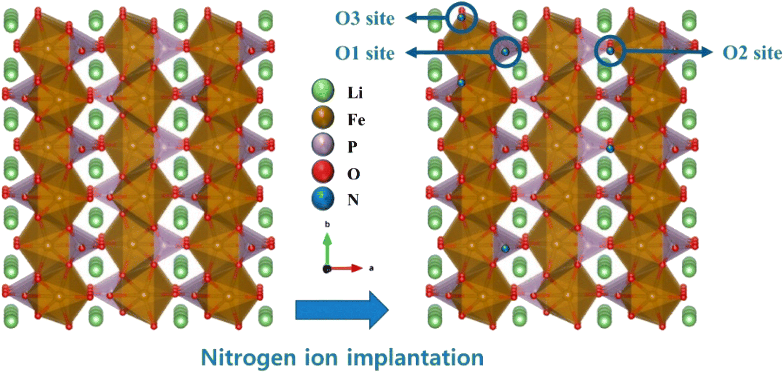 | ||
| Fig. 4 Schematic of the proposed N substitutions sites in the LFP crystal structure. | ||
The morphologies of LFP and N-substituted LFP particles were observed by FE-SEM. As shown in Fig. 5a, LFP particles had an irregular shape and particle size distribution from tens of nanometers to ∼0.5 μm. While there are no distinct differences with LFP, the edges of the N-substituted LFP particles were slightly blunted (Fig. 5b and c), which may have originated from the bombarded higher ion energy.
 | ||
| Fig. 5 FE-SEM images of (a) LFP, (b) LFP-N5, and (c) LFP-N7. | ||
Galvanostatic charge–discharge curves of the prepared electrodes were measured at 0.2C and 25 °C (Fig. 6a). The initial specific discharge capacities of LFP, LFP-N5, and LFP-N7 were 157.7, 160.6, and 163.7 mA h g−1, respectively. Specific capacity increased with increasing N content.
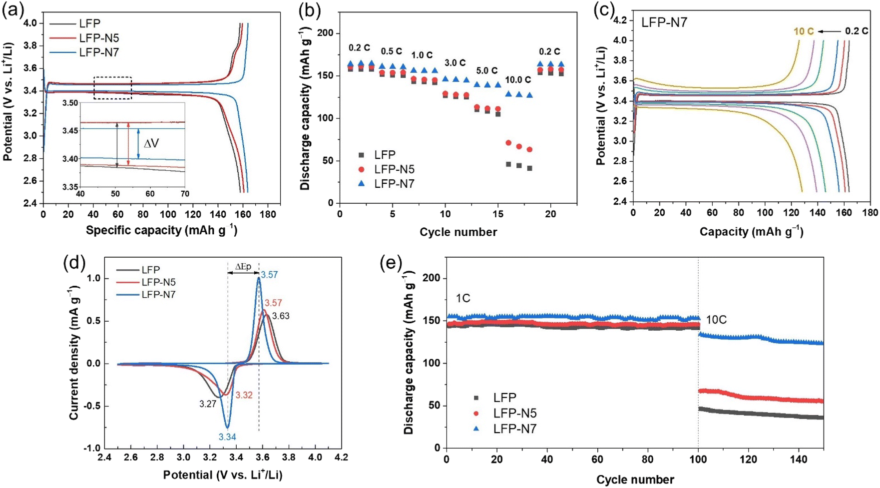 | ||
| Fig. 6 (a) Galvanostatic charge–discharge curves at 0.2C and (b) rate capability of LFP and N-substituted LFP electrodes. (c) Charge–discharge curves of LFP-N7 as a function of C-rate. (d) CV curves and (e) cyclability of LFP and N-substituted LFP electrodes. | ||
The voltage plateaus, which is well known as the two-phase region of the LiFePO4/FePO4 transformation,34 were observed in all samples with a slightly different voltage gap (ΔV) between charging and discharging. The ΔV of the charge and discharge plateaus, indicating voltage polarization during lithiation/delithiation, were approximately 80, 75 and 53 mV for LFP, LFP-N5 and LFP-N7, respectively. Thus, an increased N content resulted in a decreased ΔV, which implies lower polarization with improved ionic and electronic transportation. The rate performances were evaluated at various C-rates from 0.2 to 10C to verify the N-substitution effect in the LFP structure (Fig. 6b). Compared to non-substituted LFP, LFP-N5 exhibited improved high-rate capability with a capacity retention of 44.8% at 10C with respect to 0.2C (for LFP, capacity retention is 29.2%). In contrast, LFP-N7 exhibited greatly enhanced rate performance, showing 78.3% capacity retention even at 10C with a significantly higher discharge capacity of 128.2 mA h g−1 (46.1 and 71.2 mA h g−1 for LFP and LFP-N5, respectively). This is more clearly observed in the Galvanostatic charge–discharge curves at different C-rates (Fig. 6c and S4†). LFP-N5 showed a small improvement in capacity up to 5C, but a higher capacity with a longer voltage plateau was observed at 10C compared to that of LFP. In contrast, LFP-N7 exhibited superior electrochemical performance, including a high rate capability and significantly reduced polarization during charging and discharging. Notably, LFP-N7 showed a much narrower voltage gap depending on the C-rate (ΔV = 53, 63, 76, 115, 144, and 214 mV at 0.2 to 10C) compared with LFP and LFP-N5 (Fig. S5†). Moreover, LFP-N7 maintained a wide voltage plateau even at 10C. These results suggest that the substituted N facilitate ionic and electronic transfer from the surface to the bulk FePO4 structure, resulting in improved rate capability and high capacity.
Fig. 6d shows the CV curves measured at scan rate of 0.15 mV s−1 in the voltage range of 2.5–4.1 V. The two distinct peaks at approximately 3.3 and 3.6 V (vs. Li+/Li) are attributed to the redox peak of Fe2+ in LiFePO4 and Fe3+ in FePO4 during the charge/discharge process.35 The potential separation (ΔEp) between the two peaks tended to decrease as N substitution increased. LFP-N7 exhibited a much narrower ΔEp and highly symmetrical sharp peak compared to LFP and LFP-N5, which indicated improved electrochemical kinetics and smaller polarization.36,37 Notably, this ΔEp value and relative peak intensity can be used as indicators to determine the electrochemical reactivity and reversibility of an electrode.
The cycling stability at different current densities was evaluated to verify the effect of N substitution. Fig. 6e shows the capacity trends at a charging/discharging rate of 1C/1C followed by a 10C/10C cycle. All the samples exhibited good cycling stability for 100 cycles without any degradation. In the cycles at 10C, LFP-N7 displayed a significantly higher discharge capacity of 123.3 mA h g−1 than LFP (36.0 mA h g−1) and LFP-N5 (55.3 mA h g−1) at the 150th cycle. Moreover, the capacity retention of LFP, LFP-N5, and LFP-N7 after 150 cycles at 10C were calculated to be 77.2%, 81.9%, and 91.9%, respectively. Although, under fast reaction conditions with a high current density, LFP-N7 did not show obvious capacity degradation due to the substituted N, which could enable fast Li-ion transport.
To further investigate the conductivity of the surface-modified LFP, sheet resistance and EIS measurements were performed. The sheet resistance was measured using a four-point probe system. The order of sheet resistance was as follows, LFP (7.493 Ω sq−1) > LFP-N5 (6.852 Ω sq−1) > LFP-N7 (3.633 Ω sq−1); therefore, it decreased with increasing N substitution. Among the electrodes, LFP-N7 exhibited the lowest sheet resistance, indicating an improvement in the electronic conductivity of LFP. Fig. 7a shows the Nyquist plots of LFP, LFP-N5, and LFP-N7 obtained from the EIS measurements. The impedance spectra comprised ohmic (Rs) and charge transfer (Rct) resistance, which were fitted using the equivalent circuit model. The kinetic parameters are summarized in Table S3.† The Rct value decreased with increasing N substitution (from 123.1 Ω to 31.5 Ω for LFP and LFP-N7, respectively). Notably, the remarkably decreased Rct of LFP-N7 indicates that N substitution improves the migration of Li ions within the electrode, which is consistent with the sheet resistance trend. The Li diffusion coefficient (DLi) was calculated using following equation:38
| DLi = (2R2T2)/(n4F4σ2ACL2) |
 | ||
| Fig. 7 (a) Nyquist plots and (b) linear plots of Z′ vs. ω−1/2 in the low-frequency region of the LFP and N-substituted LFP electrodes. | ||
Based on the above results, N substitution for O sites effectively improves the electrochemical performance of LFP, which might arise from surface modifications that influence charge-transfer kinetics by mixed anion effects. Owing to the increased amount of N substitution in the surface regions, LFP-N7 exhibited improved ionic and electronic transport during lithiation/delithiation. Consequently, LFP-N7 exhibited remarkable rate capability with high capacity. Therefore, the results confirm that the N-substituted LFP electrode was in accordance with the proposed N-substituted crystal structure and its effects on the electrochemical properties. Moreover, the rate capability and capacity of LFP-N7 are superior to those of recently reported modified LFP electrodes (Table S4†). Thus, we conclude that the mixed anion effects through the introduction of N within the O sites in the (PO4)3– anions by ion implantation can be effective to improve the electrochemical performance of cathode materials.
Conclusion
In this study, an LFP electrode was modified via N substitution by PIII. XRD and XPS analyses confirmed that the introduced N was successfully substituted at the O sites of the (PO4)3– anions. The substituted N improved ionic and electronic transport, resulting in reduced charge transfer and electronic resistance. The modified anion configuration affected the electrochemical properties. Owing to its modified characteristics, LFP-N7 exhibited a superior rate capability and capacity. Moreover, it showed a wide voltage plateau with a small overpotential even at a high rate of 10C, which enabled its practical application as a fast-charge cathode material. We believe that the anionic effects introduced by N substitution will encourage the development of new strategies for improving LFP cathodes as well as other electrode materials in energy storage and conversion devices.Conflicts of interest
There are no conflicts to declare.Acknowledgements
This study has been conducted with the support of the Korea Institute of Industrial Technology as “Support Business of Customized Production Technology for Small and Medium Enterprises (KITECH UR-23-0049)”. This research was supported by Korea Research Fellowship program funded by the Ministry of Science and ICT through the National Research Foundation of Korea (2019H1D3A1A01071089).References
- J. Xu, X. Cai, S. Cai, Y. Shao, C. Hu, S. Lu and S. Ding, Energy Environ. Mater., 2023, 6, e12450 CrossRef CAS.
- A. Masias, J. Marcicki and W. A. Paxton, ACS Energy Lett., 2021, 6, 621–630 CrossRef CAS.
- Y. Kim, W. M. Seong and A. Manthiram, Energy Storage Mater., 2021, 34, 250–259 CrossRef.
- B. Xu, D. Qian, Z. Wang and Y. S. Meng, Mater. Sci. Eng., R, 2012, 73, 51–65 CrossRef CAS.
- W. Liu, P. Oh, X. Liu, M. J. Lee, W. Cho, S. Chae, Y. Kim and J. Cho, Angew. Chem., Int. Ed., 2015, 54, 4440–4457 CrossRef CAS PubMed.
- H. Zhang, Z. Zou, S. Zhang, J. Liu and S. Zhong, Int. J. Electrochem. Sci., 2020, 15, 12041–12067 CrossRef CAS.
- N. Mohamed and N. K. Allam, RSC Adv., 2020, 10, 21662–21685 RSC.
- L.-X. Yuan, Z.-H. Wang, W.-X. Zhang, X.-L. Hu, J.-T. Chen, Y.-H. Huang and J. B. Goodenough, Energy Environ. Sci., 2011, 4, 269–284 RSC.
- S.-P. Chen, D. Lv, J. Chen, Y.-H. Zhang and F.-N. Shi, Energy Fuels, 2022, 36, 1232–1251 CrossRef CAS.
- A. Tron, Y. N. Jo, S. H. Oh, Y. D. Park and J. Mun, ACS Appl. Mater. Interfaces, 2017, 9, 12391–12399 CrossRef CAS PubMed.
- E. Logan, A. Eldesoky, Y. Liu, M. Lei, X. Yang, H. Hebecker, A. Luscombe, M. B. Johnson and J. Dahn, J. Electrochem. Soc., 2022, 169, 050524 CrossRef CAS.
- D. Wang, H. Li, S. Shi, X. Huang and L. Chen, Electrochim. Acta, 2005, 50, 2955–2958 CrossRef CAS.
- J. Ying, M. Lei, C. Jiang, C. Wan, X. He, J. Li, L. Wang and J. Ren, J. Power Sources, 2006, 158, 543–549 CrossRef CAS.
- Y. Zhang, J. A. Alarco, J. Y. Nerkar, A. S. Best, G. A. Snook, P. C. Talbot and B. C. Cowie, ACS Appl. Energy Mater., 2020, 3, 9158–9167 CrossRef CAS.
- C. S. Sun, Y. Zhang, X. J. Zhang and Z. Zhou, J. Power Sources, 2010, 195, 3680–3683 CrossRef CAS.
- F. Lu, Y. Zhou, J. Liu and Y. Pan, Electrochim. Acta, 2011, 56, 8833–8838 CrossRef CAS.
- K. Okada, I. Kimura and K. Machida, RSC Adv., 2018, 8, 5848–5853 RSC.
- M. Chiesa, S. Livraghi, M. C. Paganini, E. Salvadori and E. Giamello, Chem. Sci., 2020, 11, 6623–6641 RSC.
- Z. Liu, X. Huang and D. Wang, Solid State Commun., 2008, 147, 505–509 CrossRef CAS.
- K.-S. Park, P. Xiao, S.-Y. Kim, A. Dylla, Y.-M. Choi, G. Henkelman, K. J. Stevenson and J. B. Goodenough, Chem. Mater., 2012, 24, 3212–3218 CrossRef CAS.
- G. Xu, K. Zhong, J.-M. Zhang and Z. Huang, Solid State Ionics, 2015, 281, 1–5 CrossRef CAS.
- J. Wang, M. Wang, Y. Liang, X. Liu, Y. Cui, S. Xing, H. Tao, B. Song and Z. Zhang, Phys. B, 2023, 648, 414437 CrossRef CAS.
- S. Wang and F. Wang, J. Mol. Graphics Modell., 2023, 125, 108604 CrossRef CAS PubMed.
- S. Okuda, T. Kimura and H. Akimune, Jpn. J. Appl. Phys., 1979, 18, 465 CrossRef CAS.
- K. B. Winterbon, Appl. Phys. Lett., 1977, 31, 649–651 CrossRef CAS.
- C. Wang, L. Sun, Y. Zhou, P. Wan, X. Zhang and J. Qiu, Carbon, 2013, 59, 537–546 CrossRef CAS.
- M. A. C. Solano, M. Dussauze, P. Vinatier, L. Croguennec, E. I. Kamitsos, R. Hausbrand and W. Jaegermann, Ionics, 2016, 22, 471–481 CrossRef.
- B. Wang, B. C. Chakoumakos, B. C. Sales, B. S. Kwak and J. B. Bates, J. Solid State Chem., 1995, 115, 313–323 CrossRef CAS.
- Y. Kim and H. N. G. Wadley, J. Vac. Sci. Technol., A, 2008, 26, 174–183 CrossRef CAS.
- R. K. Brow, M. R. Reidmeyer and D. E. Day, J. Non-Cryst. Solids, 1988, 99, 178–189 CrossRef CAS.
- B. K. Brow and C. G. Pantano, J. Am. Ceram. Soc., 1986, 69, 314–316 CrossRef.
- K. P. Dathar, D. Sheppard, K. J. Stevenson and G. Henkelman, Chem. Mater., 2011, 23, 4032–4037 CrossRef.
- L. Wang, F. Zhou, Y. Meng and G. Ceder, Phys. Rev. B, 2007, 76, 165435 CrossRef.
- Y. Orikasa, T. Maeda, Y. Koyama, H. Murayama, K. Fukuda, H. Tanida, H. Arai, E. Matsubara, Y. Uchimoto and Z. Ogumi, Chem. Mater., 2013, 25, 1032–1039 CrossRef CAS.
- Y. Denis, C. Fietzek, W. Weydanz, K. Donoue, T. Inoue, H. Kurokawa and S. Fujitani, J. Electrochem. Soc., 2007, 154, A253 CrossRef.
- C. Liu, Z. G. Neale and G. Cao, Mater. Today, 2016, 19, 109–123 CrossRef CAS.
- H. Kondo, T. Sasaki, P. Barai and V. Srinivasan, J. Electrochem. Soc., 2018, 165, A2047 CrossRef CAS.
- F. Gao and Z. Tang, Electrochim. Acta, 2008, 53, 5071–5075 CrossRef CAS.
Footnote |
| † Electronic supplementary information (ESI) available: Details of PIII process conditions, EDS mapping images, Rietveld refinement patterns and parameters, Li 1s and Fe 2p XPS core-level spectra, Relationship between the C-rate and voltage gap of the charge/discharge voltage plateau. See DOI: https://doi.org/10.1039/d3ra06242b |
| This journal is © The Royal Society of Chemistry 2023 |