
 Open Access Article
 This Open Access Article is licensed under a Creative Commons Attribution-Non Commercial 3.0 Unported Licence
Direct synthesis of Fe-aluminosilicates from red mud for catalytic deoxygenation of waste cooking oil
Eka Putra Ramdhani ab,
Eko Santosoa,
Holilah Holilahc,
Reva Edra Nugrahad,
Hasliza Bahrujie,
Suprapto Supraptoa,
Aishah Abdul Jalilfg,
Nurul Asikin-Mijanh,
Syafsir Akhlusa and
Didik Prasetyoko*a
ab,
Eko Santosoa,
Holilah Holilahc,
Reva Edra Nugrahad,
Hasliza Bahrujie,
Suprapto Supraptoa,
Aishah Abdul Jalilfg,
Nurul Asikin-Mijanh,
Syafsir Akhlusa and
Didik Prasetyoko*a
aDepartment of Chemistry, Faculty of Science and Data Analytics, Institut Teknologi Sepuluh Nopember, Keputih, Sukolilo, Surabaya 60111, Indonesia. E-mail: didikp@chem.its.ac.id
bDepartment of Chemistry Education, Faculty of Teacher Training and Education, Raja Ali Haji Maritime University, Dompak, Tanjungpinang, Indonesia
cResearch Center for Biomass and Bioproducts, National Research and Innovation Agency of Indonesia (BRIN), Cibinong, 16911, Indonesia
dDepartment of Chemical Engineering, Faculty of Engineering, Universitas Pembangunan Nasional “Veteran” Jawa Timur, Surabaya, East Java 60294, Indonesia
eCentre of Advanced Material and Energy Sciences, Universiti Brunei Darussalam, Jalan Tungku Link, BE 1410, Brunei
fCentre of Hydrogen Energy, Institute of Future Energy, Universiti Teknologi Malaysia, 81310, Skudai, Johor Bahru, Johor, Malaysia
gDepartment of Chemical Engineering, Faculty of Chemical and Energy Engineering, Universiti Teknologi Malaysia, 81310, Skudai, Johor Bahru, Johor, Malaysia
hDepartment of Chemical Sciences, Faculty of Science and Technology, Universiti Kebangsaan Malaysia, 43600 UKM Bangi, Selangor, Malaysia
First published on 31st October 2023
Abstract
Conversion of red mud (RM) that contains a high level of silica, alumina and iron minerals into heterogenous catalysts, offers a route for the utilization of abundant toxic by-products of bauxite refining. In this study, the conversion of red mud into mesoporous Fe-aluminosilicate produced selective catalysts for the deoxygenation of waste cooking oil to green diesel hydrocarbons. Direct conversion of red mud in the presence cetyltrimethylammonium bromide into Fe-aluminosilicate (RM-CTA) produced a highly mesoporous structure with oligomeric Fe2O3 clusters within the pores. When red mud was treated with citric acid (RM-CA-CTA), a wide distribution of Fe2O3 particles was obtained on the aluminosilicate external surface. TEM analysis showed a well-defined hexagonal mesoporosity of Fe-aluminosilicate obtained from untreated red mud, while the treated red mud produced lower regularity mesopores. RM-CTA exhibits 60% WCO conversion and 83.72% selectivity towards liquid products with 80.44% diesel hydrocarbon (C11–C18) yield. The high selectivity was due to the high acidity of Fe-aluminosilicate to dissociate the C–O bond and the regularity of mesostructure for efficient hydrocarbon diffusion, preventing a cracking reaction.
Introduction
Red mud is a residue from the bauxite refinery for alumina production. For every ton of Al2O3 extracted from bauxite, 1.5–2.5 tons of red mud were generated depending on the efficiency of the extraction process.1,2 Red mud has strong alkaline properties with a pH of ∼10–13.3 As an alkaline waste, accumulation as wet mud in rivers or ponds increases the pH of the water system. Red mud requires proper storage in a large area to prevent adverse impacts on soil and water conditions if directly discharged untreated. The leaching of harmful substances from red mud alters the mineral and microbial stability of soil and water.4 Using red mud as a source of minerals in chemical synthesis might reduce the environmental impact of red mud accumulation. Red mud is rich in alumina, silica, and iron minerals that can be used as a precursor in synthesizing zeolite, aluminosilicate, and mesoporous materials.5 Red mud has been directly used as an adsorbent6 and as raw material for the production of ceramics,7 geopolymers,8 road material,9 pavement,10 coating,11 and catalyst.12 Several researchers have utilized red mud as a catalyst due to its strong alkaline properties. Li et al. harnessed red mud as a heterogeneous Fenton catalyst.13 Hidayat et al. employed calcium/red mud catalyst to convert waste cooking oil into biodiesel through transesterification.14 This catalyst was synthesized via the wet impregnation in a metal salt solution of calcium nitrate, followed by calcination. High iron oxide content in red mud was used as an oxidative catalyst for the oxidation of volatile organic compounds,15 and for breaking C–C and/or C–H bonds in the hydrocarbon pyrolysis process.16 Thermal and chemical treatments were carried out to separate impurities in the red mud before being used in chemical synthesis. In the synthesis of ZSM-5, red mud is treated with NaOH to remove iron species that might interfere with zeolite purity.17 Some researchers treated red mud by calcination to change the crystalline phase of red mud to amorphous.18 HCl and H2SO4 were used to reduce the alkali metals in red mud,19 while KOH and ammonium oxalate were employed to create pores and to stabilize heavy metals in the red mud.20 The addition of citric acid reduced pH and total alkalinity of red mud by increasing the solubility of Na, Ca and Al.21 Direct utilization of red mud as a precursor for catalyst synthesis reduces operational costs, excludes prior treatment, and aligns with the principles of green chemistry, as it reduces the need for additional chemicals in the catalyst development process.Various studies have been carried out to seek routes for producing fuel from biomass waste, for instance, via esterification,22 hydrocracking,23 and deoxygenation.24 Esterification of fatty acid biomass requires methanol to produce fatty acid methyl ether (FAME), in which the methanol is currently generated from fossil fuel-derived syn-gas (CO + H2). The use of methanol can be avoided via hydrocracking or deoxygenation of fatty acid to form hydrocarbon biofuels. Hydrocracking removes oxygen from fatty acids via reduction under hydrogen gas at high pressure, enhancing the biofuel properties.25 On the other hand, the deoxygenation reaction removes the carbonyl group from fatty acids to generate hydrocarbon and CO/CO2 gases.26 Global consumption of biomass-derived fuel is expected to increase every year to compensate for the depletion of oil reserves.27 Green diesel is an environmentally friendly renewable fuel, generated from sustainable and renewable resources. The quality of green diesel depends on the efficiency of catalytic process, while the use of biomass waste reduced production costs and minimized waste production. Waste cooking oil (WCO) contains oleic acid and linoleic acid, suitable for conversion to green diesel.28 Vegetable oil production and consumption continue to increase, generating large amounts of WCO. Cooking at high temperatures and long hours generates a variety of toxic chemicals, raising trans-fat proportion in the oil, generating free radicals, and causing other potentially detrimental effects.29 Repeated frying causes dissolved oxygen in the oil to react with unsaturated acylglycerols, resulting in the development of various products such as dimeric and polymeric acids, dimeric and acylglycerols polyglycerol which increases the viscosity of cooking fat.30 Food processing industries and restaurants are the largest WCO producers, contributing to 47% of WCO production in the world.31 Thus, WCO conversion to green diesel while utilizing catalysts from red mud serves as an efficient waste management system to improve the value-added properties of the two industrial wastes.
Noble metals such as Pd,32 Pt,33 and Ru34 are generally employed as catalysts in deoxygenation reactions. Transition metal catalysts such as Fe and Ni have shown promising activity as heterogeneous catalysts for deoxygenation reactions.35,36 Fe complex has been employed in homogeneous decarbonylation of aliphatic carboxylic acid that showed high selectivity to α-olefins, although toxic phosphine ligand is required for the synthesis of Fe-complex catalyst. Heterogeneous Fe catalyst prevented the breakdown of C–C bonds in biomass and encouraged the hydrogenation of the C–O bonds.37,38 Ni metal catalyst reduced the polymerization of unsaturated hydrocarbons that resulted in the formation of coke.39 This study utilized hematite minerals in the red mud to generate mesoporous Fe-aluminosilicate. Red mud was used directly without chemical treatment and after citric acid treatment to synthesize Fe-aluminosilicate. Characterization analysis revealed the effect of citric acid treatment on the mesoporosity of Fe-aluminosilicate and the formation of Fe2O3 species. The synthesized Fe-aluminosilicates were employed as catalysts in the deoxygenation of waste cooking oil to produce green diesel hydrocarbon. The high selectivity of Fe-aluminosilicate exhibits the advantage of utilizing iron minerals in the red mud to transform WCO into green diesel hydrocarbons.
Experimental
Materials
Red Mud was obtained from Bintan Islands, Indonesia, containing 41.51% of O, 19.13% of Si, 26.77% of Al and 10.72% of Fe (Table 1). Waste Cooking Oil (WCO) was obtained from a local supplier. NaOH and Citric Acid (assay 99%) were obtained from Merck, Germany. LUDOX® HS-40 colloidal silica (30% silica in water) was purchased from Sigma Aldrich, Germany. CTAB (C19H42BrN, assay 99%) was purchased from Applichem. All materials used in this work were analytical grade.| Catalyst | SBETa (m2 g−1) | Smesob (m2 g−1) | Vb (c g−1) | Db (nm) | Element compositionc (%) | Acid sitesd (μmol g−1) | ||||
|---|---|---|---|---|---|---|---|---|---|---|
| Al Si Fe | O | Brønsted | Lewis | |||||||
| a SBET (specific surface area) by the BET method.b Smeso (mesopore surface areas), V (volume) and pore diameter by DFT method.c Elemental composition estimated by SEM-EDS.d Lewis Brønsted acid sites by pyridine adsorption. | ||||||||||
| RM | 56.95 | 57.13 | 0.284 | 13.68 | 26.77 | 19.13 | 10.72 | 41.51 | 5 | 13 |
| RM-CTA | 786.99 | 733.84 | 0.548 | 3.77 | 3.74 | 48.93 | 3.72 | 42.60 | 69 | 84 |
| RM-CA-CTA | 383.17 | 162.43 | 0.302 | 5.65 | 3.11 | 36.07 | 0.95 | 58.18 | 10 | 9 |
Synthesis of catalyst
Red mud was dried at 100 °C for 12 h, pulverized using a crusher, and sieved using a 200-mesh sieve. The powder was labeled as (RM) and used directly to synthesize Fe-aluminosilicate with CTAB surfactant, labeled as RM-CTA. RM-CTA catalyst was synthesized using molar composition ratio of 10 Na2O![[thin space (1/6-em)]](https://www.rsc.org/images/entities/char_2009.gif) :100 SiO2:2 Al2O3:1800H2O. Red mud served as a source of SiO2 and Al2O3 and was mixed with Ludox to increase SiO2 concentration and poured into a polyethylene bottle. The gel was then stirred for 30 min, and distilled water was added and stirred for 8 h at room temperature. The resulting mixture was heated at 70 °C for 6 h, transferred to a Teflon-line autoclave and further heated for 12 h at 80 °C. CTAB was added slowly after the mixture was cooled to room temperature, at SiO2/CTAB ratio of 3.85, and stirred for 1 h. The mixture was then heated at 150 °C for 24 h. The solid was filtered and washed with distilled water until the pH was neutral. The solid was dried at 60 °C for 24 h, followed by calcination at 550 °C, at 2 °C min−1 ramp rate and under N2 flow for 1 h. The N2 flow was switched off, and the calcination was continued in the air for another 6 h.
:100 SiO2:2 Al2O3:1800H2O. Red mud served as a source of SiO2 and Al2O3 and was mixed with Ludox to increase SiO2 concentration and poured into a polyethylene bottle. The gel was then stirred for 30 min, and distilled water was added and stirred for 8 h at room temperature. The resulting mixture was heated at 70 °C for 6 h, transferred to a Teflon-line autoclave and further heated for 12 h at 80 °C. CTAB was added slowly after the mixture was cooled to room temperature, at SiO2/CTAB ratio of 3.85, and stirred for 1 h. The mixture was then heated at 150 °C for 24 h. The solid was filtered and washed with distilled water until the pH was neutral. The solid was dried at 60 °C for 24 h, followed by calcination at 550 °C, at 2 °C min−1 ramp rate and under N2 flow for 1 h. The N2 flow was switched off, and the calcination was continued in the air for another 6 h.
The synthesis method was repeated on treated red mud with citric acid. Red mud was treated by adding 1 M citric acid solution (red mud/acid ratio 1:5 g ml−1) to dried red mud and stirring at 90 °C for 2 h. The mixture was centrifuged to separate the powder from the supernatant. The solid was dried at 110 °C for 12. The synthesis followed similar procedures to produce RM-CA-CTA.
Characterization catalysts
X-ray diffraction (XRD) was performed using a Bruker D8 Advance, with Cu Kα (λ = 1.5406 Å), and the scan rate employed was 0.2° min−1 for a 2θ (5°–50°). The morphologies of the samples were examined using Scanning Electron Microscope – Energy Dispersive X-ray (SEM ZEISS EVO MA 10 using a 30 kV and EDX BRUKER 129 EV) to know the morphology of the sample. Total surface area, pore size distribution, and total pore volume were determined from N2 adsorption–desorption using a Quantachrome Instruments Nova 1200. The total surface area was determined by the BET and pore size distribution and volume in the mesoporous were determined from the BJH method. For TEM analysis, high-resolution images were recorded using a JEM 1400 instrument operating at 120 kV.Catalytic performance
The catalytic activity was determined in the deoxygenation reaction of waste cooking oil. The synthesized Fe-aluminosilicate catalyst was activated by heating at 150 °C for an hour to remove moisture. The deoxygenation reaction is carried out in a semi-batch reactor, integrated with a distillation apparatus. In this setup, 10 g of WCO and 3 wt% of the catalyst were added into a 100 ml three-necked round-bottom flask connected to a condenser. No solvent was added in the mixture. The reaction was conducted at 350 °C ± 5 °C, under continuous flow of N2 gas at 50–100 mL min−1. The reaction was carried out at atmospheric pressure and without simultaneous hydrogen co-feeding. The volatile product was condensed into liquid and collected in a collection flask. Simultaneously, the uncondensed gaseous product was vented from the system and analyzed with CO and CO2 detectors.Deoxygenated liquid product analysis
The liquid product was characterized using the Shimadzu Gas chromatography-mass spectroscopy (QP 2010 SE) with column Rtx 5MS (5% diphenyl/95% dimethyl polysiloxane). The conversion was calculated based on the residual amount of waste cooking oil after the reaction (eqn (1)). Meanwhile, the selectivity of liquid products, solid char and non-condensable gas was determined based on the percentage of weight as shown in eqn (2)–(4).
 | (1) |
 | (2) |
 | (3) |
 | (4) |
Results and discussion
Characterization of catalyst
The XRD pattern of the red mud in Fig. 1a consists of a crystalline phase of hematite at 2θ = 36° and 39° (JCPDS no. 89-0597), silicon dioxide at 2θ = 12°, 21° and 34° (JCPDS no. 82-1574), and gibbsite at 2θ = 18°, 20°, 24°, 37° and 38° (JCPDS no. 33-0018).40 The resulting powder from hydrothermal synthesis, RM-CTA and RM-CA-CTA showed no crystalline peaks, suggesting the transformation of red mud into amorphous materials.41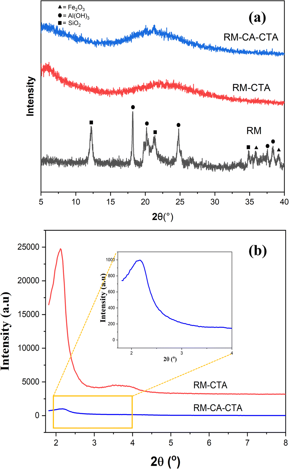 | ||
| Fig. 1 Wide-angle (a) and low angle XRD pattern (b) of RM, RM-CA-CTA, RM-CTA. | ||
The aluminosilicate catalysts are observed by a broad amorphous peak as the typical pattern of amorphous aluminosilicate.42 Characteristic peaks of Fe2O3 and other Fe species were not found for RM-CTA and RM-CA-CTA samples, which suggested that iron species might be in the framework or highly dispersed on the surface of the catalyst.43 The low-angle XRD patterns of RM-CTA and RM-CA-CTA are shown in Fig. 1b. A peak at 2θ = 2.2° was observed in RM-CTA and RM-CA-CTA catalysts, indicating the presence of mesoporous hexagonal pore arrangement.44 The difference in peak intensity suggests that the RM-CTA catalyst has a higher mesoporous regularity than RM-CA-CTA.
FTIR analysis of RM, RM-CTA, and RM-CA-CTA catalysts was determined to see vibrational changes in the red mud and the synthesized catalysts (Fig. 2). In general, there are no significant changes in the FTIR bands apart from the changes in intensity. Red mud and the synthesized Fe-aluminosilicate catalysts exhibit the absorption bands at 1629, 1230, 1082, 960, 796, 570 and 457 cm−1, which can be assigned to different tetrahedral framework atoms vibrations in the silicate structure. The broad absorption band near 3400 cm−1 and the peak at 1629 cm−1 are attributed to the hydroxyl vibration mode of the surface Si–OH groups.45 The intensity enhanced on the synthesized catalysts, suggesting the incorporation of a high-density water or OH group in the structure. The peaks at 1082 and 796 cm−1 were attributed to external linkage vibrations in the silicate structure. The broad peak at 1082 cm−1 is assigned to asymmetric Si–O–Si vibrations, while the peak centered at 796 cm−1 is due to the symmetric Si–O–Si vibrations. The absorption peak at 960 cm−1 is assigned to the Si–OH.46 The peak at 570 cm−1 assigned to Fe–O bending vibration was reduced on the Fe-aluminosilicate, which implies the reduction of Fe concentration.47,48 The characteristic band of Si–O–Si (SiO4 tetrahedron) bending vibrations appeared at 457 cm−1.49
 | ||
| Fig. 2 FTIR spectra of RM, RM-CA-CTA, RM-CTA. | ||
Fig. 3 shows the infrared spectra of the RM, RM-CTA, and RM-CA-CTA catalysts in 1400–1650 cm−1 following adsorption with pyridine. The pyridine ring vibration is analyzed to determine the concentration of Brønsted and Lewis acid sites.50 The Brønsted acid site is evaluated using the pyridinium ion band at 1545 cm−1. Lewis acid site is determined from the pyridines that are coordinated to Al3+ at 1450 cm−1. Pyridine-FTIR spectra on all catalysts show three peaks at 1545, 1450 and 1490 cm−1. These peaks appeared at a lower intensity on RM and RM-CA-CTA compared to RM-CTA catalysts. The band at 1490 cm−1 is attributed to the vibration of the pyridine ring on both Brønsted and Lewis acid sites in the RM, RM-CTA, and RM-CA-CTA catalysts.51
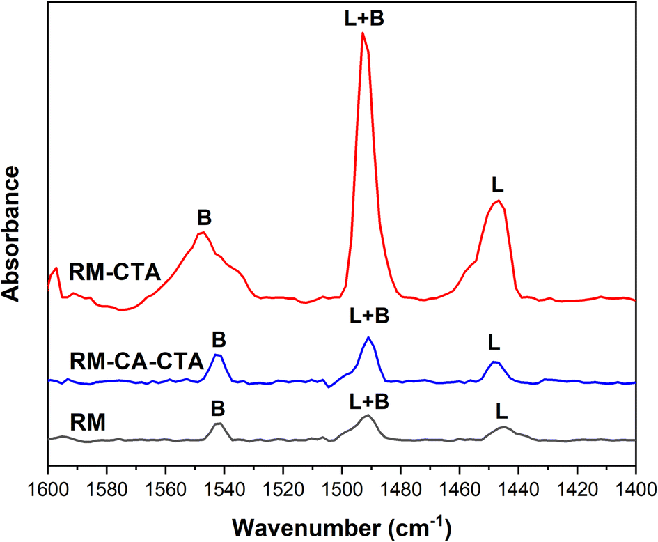 | ||
| Fig. 3 Pyridine adsorption spectra of RM, RM-CA-CTA, RM-CTA. | ||
Quantitative analysis of the peak area provides the amount of Brønsted and Lewis acid sites in RM, RM-CTA, and RM-CA-CTA as summarized in Table 1. The highest number of Brønsted acid sites of 69 μmol g−1 and Lewis acid sites of 84 μmol g−1 were measured in the RM-CTA catalyst. Aluminosilicate produced from treated red mud, RM-CA-CTA has lower Brønsted and Lewis acid sites than Fe-aluminosilicate, RM-CTA. Analysis was also conducted on the red mud that indicates a small number of acid sites, presumably arising from the amphoteric properties of alumina and hematite. The acidity of aluminosilicate is generated from the Al atoms, in which at a high ratio of silica/aluminium (Si/Al), the high proportion of Al compared to Si enhanced the amount of Brønsted acid sites.52 There is a possibility that Fe presence in the aluminosilicate further contributed to the Lewis acidity of Fe-aluminosilicate. High oxidation states of Fe, either as Fe(II) or Fe(III) possess Lewis acid properties.53 During bond dissociation, the Fe species can coordinate with oxygen or nitrogen atoms of the C![[double bond, length as m-dash]](https://www.rsc.org/images/entities/char_e001.gif) O and CN double bonds.54 A large surface area of RM-CTA generates a higher extra framework aluminium and might also expose more Fe species on the surface, enhancing the overall number of acid sites.
O and CN double bonds.54 A large surface area of RM-CTA generates a higher extra framework aluminium and might also expose more Fe species on the surface, enhancing the overall number of acid sites.
The textural properties of the RM measured using the N2 adsorption–desorption analysis showed a mixture of type II and type IV isotherms (Fig. 4a). This indicates that RM consists of a large mesopore with a broad pore size distribution up to a macropore size.55 The hysteresis loop is narrow, with the adsorption and desorption branches almost vertical at P/P0 above 0.8. The N2 adsorption–desorption analysis indicates the red mud has a 56.95 m2 g−1 of external surface area.56 The RM-CTA isotherm shows a steep step at P/P0 = 0.2–0.4 due to nitrogen condensation in the primary mesoporous, as a characteristic of type IV isotherm (Fig. 4b).57 Type IV isotherm has three regions of mild N2 uptake at low relative pressure, indicating monolayer N2 adsorption. The sharp inflection between 0.4 < P/P0 < 0.95 implies the capillary condensation in the mesopore.58 The RM-CA-CTA catalysts have type IV isotherm with type H4 hysteresis, indicating the presence of slit-shaped and non-uniform size mesopores.59
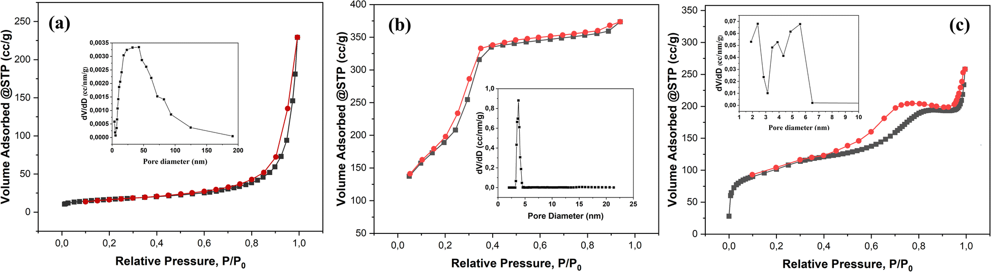 | ||
| Fig. 4 N2 adsorption–desorption isotherm and pore size distribution of RM (a), RM-CTA (b), RM-CA-CTA (c). | ||
Fig. 4a–c shows the pore size distribution obtained from the nitrogen adsorption isotherm. RM-CTA shows a narrow mesopores distribution with an average diameter of ∼3.77 nm. RM-CA-CTA catalyst shows multiple adsorptions between 2–6 nm with an average pore size of 5.65 nm. The resulting aluminosilicate catalysts contained mesoporosity, indicating upgraded textural properties compared to the red mud. Table 1 shows the calculated pore size, pore volume, and mesoporous volume of the RM, RM-CTA, and RM-CA-CTA catalysts. The RM-CTA catalyst has the highest SBET of 786.99 m2 g−1, followed by RM-CA-CTA at SBET of 383.17 m2 g−1. RM-CTA has a large pore volume of 0.548 cm3 g−1 followed by RM-CA-CTA at 0.302 cm3 g−1, and RM at 0.284 cm3 g−1.
The surface morphology and elemental mapping of the RM, RM-CTA, and RM-CA-CTA catalysts can be seen in Fig. 5a–f. SEM analysis of red mud (RM) shows non-uniform aggregates with a homogenous distribution of Fe in the minerals (Fig. 5a–c). Slightly different morphology was observed on RM-CTA and RM-CA-CTA catalysts, with approximately rounder and larger crystallites. No significant differences can be observed in the morphology of the two catalysts. The EDS analysis showed a homogeneous distribution of Fe particles. The elemental analysis in Table 1 showed that 3.75% of Fe was detected on RM-CTA, and 0.95% of Fe was analyzed on RM-CA-CTA. Fe concentration was significantly lower than the red mud (10.72%), suggesting the dissolution of hematite has occurred that reduced the incorporation of Fe into the aluminosilicate framework. Further reduction of Fe concentrations on RM-CA-CTA implied the removal of Fe has occurred during citric acid treatment of red mud. The concentration of Si is also higher in RM-CA-CTA than RM-CTA, indicating the aluminosilicates have different efficiencies in incorporating the additional colloidal SiO2 in the framework during hydrothermal synthesis. EDS data show a slightly similar amount of aluminium in the RM-CTA and RM-CA-CTA catalysts, at 3.74%, and 3.11%, respectively (Table 1).
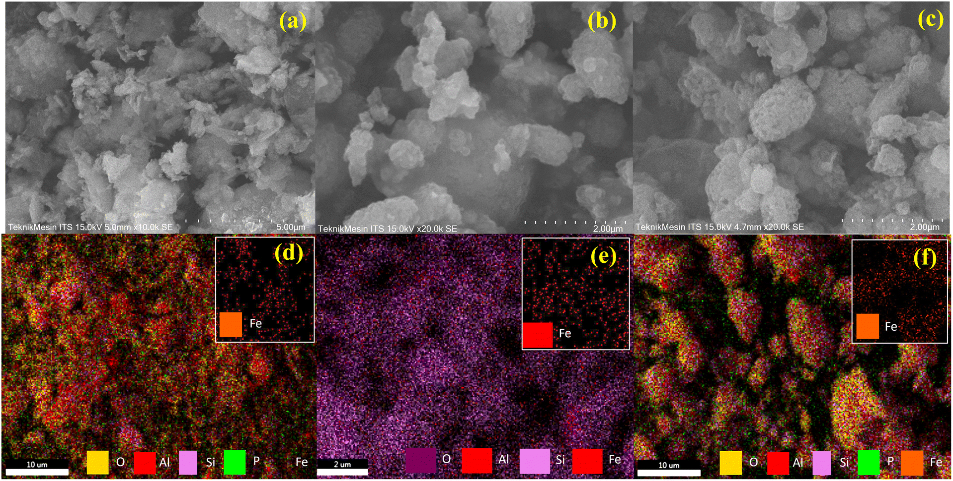 | ||
| Fig. 5 SEM analysis of RM (a), RM-CTA (b), RM-CA-CTA (c), EDX mapping of RM (d), RM-CTA (e), RM-CA-CTA (f). | ||
Fig. 6 displayed the TEM analysis of the mesoporous RM-CTA and RM-CA-CTA catalysts. RM-CTA shows a well-defined, two-dimensional mesopore channel estimated at 3.15 nm diameter. The average mesopore diameter is approximately similar to the pore diameter obtained from N2 analysis. The RM-CA-CTA exhibited less-defined mesoporous structures compared to RM-CTA. The results are in agreement with the low-angle XRD analysis in Fig. 1b. The results derived from TEM analysis confirmed the formation of mesoporous long-range order of Fe-aluminosilicate obtained from direct synthesis using untreated red mud. The TEM analysis of RM-CA-CTA also showed the formation of spherical Fe2O3 particles, with high density contrast due to the difference in electronic density between Fe and aluminosilicate.60 The diameter of Fe2O3 was estimated between 5-15 nm, indicating the deposition of Fe2O3 on the external surface of aluminosilicate. However, no visible dark shade particles were observed on RM-CTA, presumably due to no large Fe2O3 crystallites were formed that can be detected using TEM.
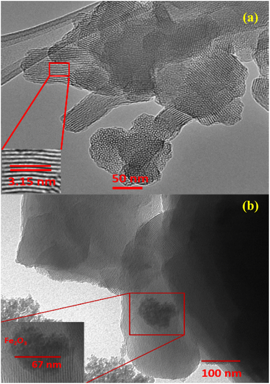 | ||
| Fig. 6 TEM images of RM-CTA (a) and RM-CA-CTA (b). | ||
Analysis of Fe2O3 in aluminosilicate
Fe3+ species in aluminosilicate were analyzed using UV-visible diffuse reflectance spectroscopy and H2-TPR analysis. The absorption band of Fe3+ species depends on the position of Fe in the aluminosilicate framework (Fig. 7). A small peak appeared at 210 nm in RM-CTA and RM-CTA-CA was ascribed to the oxygen-to-iron charge transfer of isolated coordinated Fe3+ sites in tetrahedral.61 A high intensity absorbance at 272 nm in RM-CTA indicated most of the Fe species existed as oligomeric Fe2O3 in higher coordination, presumably within the aluminosilicate pores. This species could also be related to the interaction between Fe/Al in the minerals.62 No absorbance beyond 350 nm was observed on RM-CTA, implying the highly dispersed Fe2O3 nanoparticles within the mesoporous channel of aluminosilicate.63 On the other hand, the catalyst produced from the red mud following citric acid treatment showed extended absorbance in the visible region with two shoulder bands at 374 nm and 531 nm, indicating the formation of large Fe2O3 clusters. Absorption within 350–450 nm was assigned to the formation of larger extra-framework Fe clusters, and adsorption at 520 nm was suggested by the formation of FexOy particles on the external surface of aluminosilicate.64 The results from UV-vis analysis implied the formation of different Fe species on aluminosilicate when synthesized using fresh red mud and red mud treated with citric acid.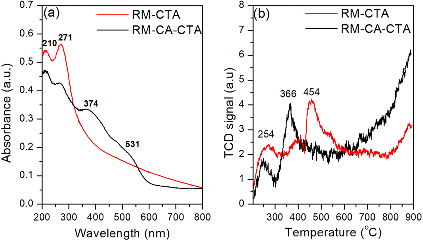 | ||
| Fig. 7 UV-vis diffuse reflectance spectroscopy (a) and H2-TPR analysis (b) of RM-CTA and RM-CA-CTA. | ||
H2-TPR analysis was conducted to support further the results obtained in UV-visible analysis. Fig. 7b showed two main peaks at 254 °C and 366 °C on the RM-CTA catalyst. The reduction of isolated Fe2O3 within the aluminosilicate domain occurred at ∼250 °C.65 The reduction of oligomeric Fe2O3 to FeO occurred at the temperature range of 350–450 °C,66 with no reduction profiles detected at higher temperatures up to 800 °C. The spatial constraints of the uniform porous channel of the aluminosilicate restricted further reduction of FeO into Fe0. The slight increase at temperatures above 800 °C is due to the disintegration of the aluminosilicate framework, allowing further reduction of FeO to Fe.67,68 On RM-CA-CTA catalyst, the isolated extra-framework Fe2O3 species were observed at a slightly low temperature of 250 °C. The reduction of Fe3+ to Fe2+ occurred at 360 °C, slightly lower than RM-CTA. The shift to lower temperatures implies that the ferric species in RM-CA-CTA are present at the external surface or outside the pore of aluminosilicate, therefore more susceptible to reduction.63 RM-CA-CTA also showed continuous H2 uptakes at high temperatures, suggesting the continuous release of framework Fe(III) for further reduction that might occur via the successive reduction of Fe2O3 → Fe3O4 → FeO → Fe.66
Catalytic deoxygenation of waste cooking oil
The catalytic activity of RM-CTA and RM-CA-CTA were measured in deoxygenation of WCO at 370 °C for 4 h, under N2 flow. The triglycerides of WCO used in this reaction consist of 37.1% palmitic acid and 42.8% oleic acid. Based on the conversion data in Fig. 8a, RM-CTA catalyst achieved a higher WCO conversion at 51.91% compared to RM-CA-CTA at 46.28%. Fig. 8a also shows product selectivity, which is divided into liquid yield, gas and carbon char. Ideally, the deoxygenation of fatty acid will produce a liquid hydrocarbon yield from the removal of carbonyl group. However, the reaction is also hampered by a cracking reaction to form uncondensed gas and carbon coke. RM-CTA produced a higher percentage of liquid yield at 28.88%, while 19.15% of the oil was converted into carbon char, and 3.88% as a gas product. The liquid yield contained a mixture of hydrocarbons, aromatics, ketones, carboxylic acids, and alcohol compounds. Further analysis of the liquid products using GCMS showed that the deoxygenation using RM-CTA catalysts produced 83.72% hydrocarbon selectivity compared to RM-CA-CTA at 54.16% (Fig. 8b). The liquid yield from the RM-CTA catalyst also consists of ketone compounds and small percentages of carboxylic acid and aromatics. Liquid products obtained from RM-CA-CTA catalyst showed less composition of hydrocarbons but a higher percentage of aromatic than RM-CTA. The presence of carboxylic acid is also higher than RM-CTA.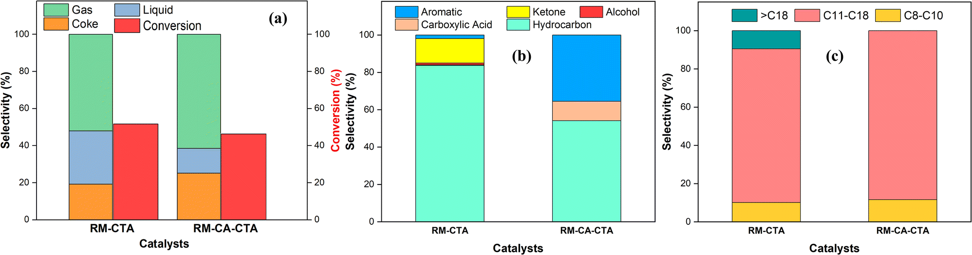 | ||
| Fig. 8 Selectivity and conversion product (a) selectivity of liquid products (b), hydrocarbon selectivity from catalytic deoxygenation (c) of RM-CTA and RM-CA-CTA. | ||
Fig. 8c divides the hydrocarbon yields into gasoline (C8–10), diesel (C11–18), and heavy oil (![[double bond splayed left]](https://www.rsc.org/images/entities/char_e009.gif) C18) composition. The catalysts mainly produced diesel (C11–18) with more than 80% selectivity. However, RM-CTA also produced heavy oil with C18 hydrocarbon products, while no C18 hydrocarbon was analyzed from RM-CA-CTA catalysts. Both catalysts produced short-chain hydrocarbons (C8–C14) at approximately similar selectivity of ∼9%, which confirmed the hydrocracking occurred during the deoxygenation reaction. Deoxygenation and hydrocracking required solid acid catalysts to dissociate the C–C bonds and increase oil conversion to hydrocarbons. However, it was suggested that hydrocracking mainly occurs on Brønsted acid sites, while the deoxygenation reaction requires a high concentration of Lewis acid.69
C18) composition. The catalysts mainly produced diesel (C11–18) with more than 80% selectivity. However, RM-CTA also produced heavy oil with C18 hydrocarbon products, while no C18 hydrocarbon was analyzed from RM-CA-CTA catalysts. Both catalysts produced short-chain hydrocarbons (C8–C14) at approximately similar selectivity of ∼9%, which confirmed the hydrocracking occurred during the deoxygenation reaction. Deoxygenation and hydrocracking required solid acid catalysts to dissociate the C–C bonds and increase oil conversion to hydrocarbons. However, it was suggested that hydrocracking mainly occurs on Brønsted acid sites, while the deoxygenation reaction requires a high concentration of Lewis acid.69
The deoxygenation temperature, LHSV (Liquid Hourly Space Velocity), and the temperature used during catalyst preparation can have an impact on the composition of by-products in the deoxygenation process as well.79 The catalytic deoxygenation of WCO using Fe-aluminosilicate catalyst produces green diesel hydrocarbon via two primary processes, namely decarbonylation (DCO) and decarboxylation (DCO2). The WCO comprises C12:0 to C20:3 fatty acid molecules, with 40.02% oleic acid (C18:1) and 34.72% palmitic acid (C16:0).72 Straight-chain hydrocarbons formed through DCO/DCO2 reactions, removing carboxylate and/or carbonyl fragments from fatty acids.73 The proposed mechanism of WCO conversion to green diesel hydrocarbon was depicted in Scheme 1. The first reaction step is the β-elimination of hydrogen to break triglyceride C–C bonds, forming one unit of carboxylic acid/fatty acid.74 The carboxylic acid subsequently undergoes decarboxylation/decarbonylation (deCOx) reaction, removing the carbonyl group as CO2 and CO gases, producing hydrocarbon with one less carbon chain from the parent fatty acid. H2 is generated in situ during the decarbonylation process via the water gas shift reaction.75 The ketone compound was also observed in this study via ketonic decarboxylation of carboxylic acid.76 The formation of mono-aromatic compounds involves the dehydrogenation reaction of cycloalkane compounds with six carbon atoms and alkenes, while polyaromatics are formed through polymerization and dehydrogenation reactions of mono-aromatic compounds or intramolecular radical cyclization mechanisms.77,78
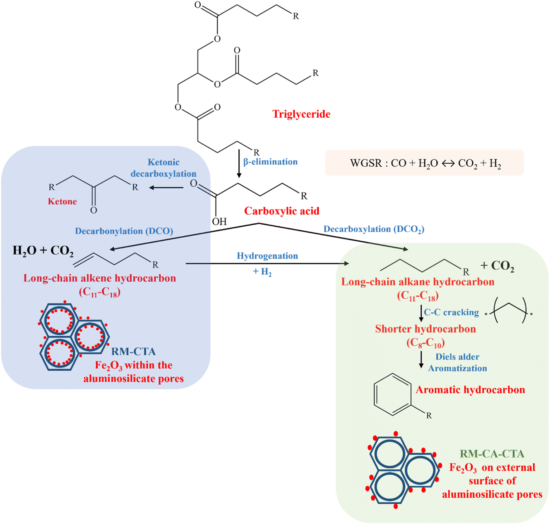 | ||
| Scheme 1 Catalytic transformation of WCO to green diesel on RM-CTA catalyst. | ||
The Fe2O3 position in the aluminosilicate strongly influenced the reaction mechanism. Non-treated red mud produces aluminosilicate with small Fe2O3 clusters predominantly confined in the well-defined hexagonal mesopores. The highly dispersed Fe2O3 increased the Lewis acidity of the RM-CTA catalysts, which is crucial to catalyze C–O bond dissociation. Studies on Fe-based catalysts for the hydrodeoxygenation of aromatic compounds suggested the importance of maintaining the stability of Fe species.70 Fe tends to interact with the oxygen atom on the carbonyl group as the main step towards deoxygenation reaction.71 The synergy between high acidity and uniform mesoporosity produces selectivity towards long-chain hydrocarbon. Direct conversion of raw red mud into Fe-aluminosilicate was suggested to provide close crystal growth within the Fe3+ ion, allowing self-assembly of Fe2O3 nanoparticles within the mesopores. This study has revealed the advantage of well-dispersed Fe2O3 in enhancing Lewis acidity, surface area and mesoporosity of aluminosilicate, consequently enhanced deoxygenation of WCO into green diesel hydrocarbons.
However, modification of hematite in the red mud by treating with citric acid significantly altered the mesoporosity of aluminosilicate and the dispersion of Fe2O3. Citric acid reduced the alkalinity of red mud by reaction with the OH− and CO32− anions, forming the citrate compounds.21 Furthermore, organic acid is used to remove iron contamination in minerals such as kaolin and quartz.80 Citric acid acts as a complexing agent to increase the dissolution of iron species.81 Pre-treatment of red mud in citric acid transformed hematite into Fe(III) complex. The dissolution of hematite can be achieved when accompanied by reducing agents such as EDTA or sodium thiosulfate to form Fe(II) complex.82 However, citric acid alone is unable to reduce Fe3+ to Fe2+.83 The adsorption and saturation of citric acid on the hematite surface, forming Fe(III) complex, presumably responsible for forming large Fe2O3 species on aluminosilicate. Furthermore, the changes in alkalinity inadvertently reduce CTAB inclusion during the amorphous gel rearrangement due to poor CTAB and AlO−/SiO− interaction.
Conclusions
Utilization of a readily available Fe mineral in red mud produced selective Fe-aluminosilicate catalysts for the deoxygenation of waste cooking oil into green diesel hydrocarbon. Oligomeric Fe2O3 clusters within the well-defined mesopores (RM-CTA) were formed when red mud was directly used without prior chemical treatment. The Fe-aluminosilicate (RM-CTA) has high acidity, a large surface area SBET at 786 m2 g−1 and a well-defined mesoporous channel, producing the largest hydrocarbon selectivity of 83.72% with diesel product selectivity (C11–C18) of 80.44%. However, reducing the acidity and mesoporosity of Fe-aluminosilicate has changed the liquid product distribution to predominantly hydrocarbon and aromatic compounds. Modification of hematite mineral in red mud using citric acid transformed the Fe2O3 into Fe(III) complex, consequently resulting in the formation of large Fe2O3 aggregates in aluminosilicate. Citric acid treatment also reduced the alkalinity of red mud and caused poor CTAB/AlO- interaction for the formation of well-defined mesopores.Author contributions
Eka Putra Ramdhani: conceptualization, methodology, data curation, formal analysis, investigation, writing-original draft. Eko Santoso: supervision, validation, writing – review & editing. Holilah Holilah: data curation, formal analysis, investigation, visualization, writing-original draft. Reva Edra Nugraha: formal analysis, investigation, visualization, writing-original draft. Hasliza Bahruji: conceptualization, supervision, validation, writing – review & editing. Suprapto Suprapto: writing – review & editing. Aishah Abdul Jalil: validation, writing – review & editing. Nurul Asikin-Mijan: validation, writing – review & editing. Syafsir Akhlus: validation, writing – review & editing. Didik Prasetyoko: funding acquisition, conceptualization, supervision, validation, writing – review & editing.Conflicts of interest
There are no reported financial or personal conflicts of interest by the authors of this study.Acknowledgements
The authors would like to thank Ministry of Education, Culture, Research and Technology, Indonesia for their financial support under PDD research grant no. 1391/PKS/ITS/2023.Notes and references
- Y. Hu, S. Liang, J. Yang, Y. Chen, N. Ye, Y. Ke, S. Tao, K. Xiao, J. Hu, H. Hou, W. Fan, S. Zhu, Y. Zhang and B. Xiao, Constr. Build. Mater., 2019, 200, 398–407 CrossRef CAS.
- A. L. Almutairi, B. A. Tayeh, A. Adesina, H. F. Isleem and A. M. Zeyad, Case Studies in Construction Materials, 2021, 15, 1–20 CrossRef.
- G. Choe, S. Kang and H. Kang, Materials, 2020, 13, 2–17 Search PubMed.
- S. M. A. Qaidi, B. A. Tayeh, H. F. Isleem, A. R. G. de Azevedo, H. U. Ahmed and W. Emad, Case Studies in Construction Materials, 2022, 16, 1–28 Search PubMed.
- T. Hertel, A. van den Bulck, B. Blanpain and Y. Pontikes, Cem. Concr. Compos., 2022, 127, 1–13 CrossRef.
- N. Deihimi, M. Irannajad and B. Rezai, J. Environ. Manage., 2018, 206, 266–275 CrossRef CAS PubMed.
- Y. Kim, M. Kim, J. Sohn and H. Park, J. Cleaner Prod., 2018, 203, 957–965 CrossRef.
- Y. Li, X. Min, Y. Ke, D. Liu and C. Tang, Waste Manage., 2019, 83, 202–208 CrossRef CAS PubMed.
- J. Zhang, Z. Yao, K. Wang, F. Wang, H. Jiang, M. Liang, J. Wei and G. Airey, Constr. Build. Mater., 2021, 270 CAS.
- E. Mukiza, L. L. Zhang, X. Liu and N. Zhang, Resour., Conserv. Recycl., 2019, 141, 187–199 CrossRef.
- J. Feng, S. Liu, J. Y. Hwang, W. Mo, X. Su, S. Ma and Z. Wei, Constr. Build. Mater., 2022, 349, 128755 CrossRef CAS.
- T. Rahman, H. Jahromi, P. Roy, S. Adhikari, E. Hassani and T. S. Oh, Energy Convers. Manage., 2021, 245, 114615 CrossRef CAS.
- H. Li, B. Shi, X. Fu, H. Zhang and H. Yang, J. Environ. Chem. Eng., 2023, 11, 109998 CrossRef CAS.
- A. Hidayat, G. K. Roziq, F. Muhammad, W. Kurniawan and H. Hinode, in Materials Science Forum, Trans Tech Publications Ltd, 2020, vol. 991 MSF, pp. 144–149 Search PubMed.
- W. G. Shim, J. W. Nah, H. Y. Jung, Y. K. Park, S. C. Jung and S. C. Kim, J. Ind. Eng. Chem., 2018, 60, 259–267 CrossRef CAS.
- J. Wang, S. Zhang, D. Xu and H. Zhang, Fuel, 2022, 323, 124278 CrossRef CAS.
- R. Subagyo, H. Tehubijuluw, W. P. Utomo, H. D. Rizqi, Y. Kusumawati, H. Bahruji and D. Prasetyoko, Arabian J. Chem., 2022, 15, 103754 CrossRef CAS.
- M. HM Ahmed, N. Batalha, Z. A. ALOthman, Y. Yamauchi, Y. Valentino Kaneti and M. Konarova, Chem. Eng. J., 2022, 430, 132965 CrossRef.
- G. Wang, Y. Wang, J. Lv, Y. Wu, L. Jin, Y. Li, H. Yang, B. Hou and H. Hu, J. Energy Inst., 2022, 104, 1–11 CrossRef CAS.
- G. Jiang, H. Li, T. Cheng, Y. Tian, P. Liu, J. Guo, K. Cui, R. Ma, X. Ma, F. Cui, C. Chen and Y. Hao, Chem. Phys. Lett., 2022, 806, 139993 CrossRef CAS.
- X. Kong, M. Li, S. Xue, W. Hartley, C. Chen, C. Wu, X. Li and Y. Li, J. Hazard. Mater., 2017, 324, 382–390 CrossRef CAS.
- P. S. Mateos, M. B. Navas, S. R. Morcelle, C. Ruscitti, S. R. Matkovic and L. E. Briand, Catal. Today, 2021, 372, 211–219 CrossRef CAS.
- C. H. Zandonai, P. H. Yassue-Cordeiro, S. B. Castellã-Pergher, M. H. N. O. Scaliante and N. R. C. Fernandes-Machado, Fuel, 2016, 172, 228–237 CrossRef CAS.
- F. P. Sousa, L. N. Silva, D. B. de Rezende, L. C. A. de Oliveira and V. M. D. Pasa, Fuel, 2018, 223, 149–156 CrossRef CAS.
- W. T. Hartati, R. R. Mukti, I. A. Kartika, P. B. D. Firda, S. D. Sumbogo, D. Prasetyoko and H. Bahruji, J. Energy Inst., 2020, 93, 2238–2246 CrossRef CAS.
- Z. Sun, H. Liu, H. Bai, S. Yu, C. K. Russell, L. Zeng and Z. Sun, Chem. Eng. J., 2022, 428, 132068 CrossRef CAS.
- V. G. Yadav, G. D. Yadav and S. C. Patankar, Clean Technol. Environ. Policy, 2020, 22, 1757–1774 CrossRef PubMed.
- M. S. Gamal, N. Asikin-Mijan, W. N. A. W. Khalit, M. Arumugam, S. M. Izham and Y. H. Taufiq-Yap, Fuel Process. Technol., 2020, 208, 106519 CrossRef CAS.
- A. da S. César, D. E. Werderits, G. L. de Oliveira Saraiva and R. C. da S. Guabiroba, Renewable Sustainable Energy Rev., 2017, 72, 246–253 CrossRef.
- B. H. H. Goh, C. T. Chong, Y. Ge, H. C. Ong, J. H. Ng, B. Tian, V. Ashokkumar, S. Lim, T. Seljak and V. Józsa, Energy Convers. Manage., 2020, 223 Search PubMed.
- C. Chen, A. Chitose, M. Kusadokoro, H. Nie, W. Xu, F. Yang and S. Yang, Energy Rep., 2021, 7, 4022–4034 CrossRef.
- S. Wang, H. Jin, Y. Deng and Y. Xiao, J. Cleaner Prod., 2021, 289 CAS.
- M. B. Griffin, G. A. Ferguson, D. A. Ruddy, M. J. Biddy, G. T. Beckham and J. A. Schaidle, ACS Catal., 2016, 6, 2715–2727 CrossRef CAS.
- L. J. Konwar and J. P. Mikkola, Appl. Catal., A, 2022, 638, 118611 CrossRef CAS.
- N. A. Rashidi, E. Mustapha, Y. Y. Theng, N. A. A. Razak, N. A. Bar, K. B. Baharudin and D. Derawi, Fuel, 2022, 313, 122695 CrossRef CAS.
- F. Wang, H. Xu, S. Yu, H. Zhu, Y. Du, Z. Zhang, C. You, X. Jiang and J. Jiang, Renew Energy, 2022, 197, 40–49 CrossRef CAS.
- S. Cheng, L. Wei, J. Julson, K. Muthukumarappan and P. R. Kharel, Fuel Process. Technol., 2017, 167, 117–126 CrossRef CAS.
- S. Maetani, T. Fukuyama, N. Suzuki, D. Ishihara and I. Ryu, Chem. Commun., 2012, 48, 2552–2554 RSC.
- M. M. Ambursa, J. C. Juan, Y. Yahaya, Y. H. Taufiq-Yap, Y. C. Lin and H. V. Lee, Renewable Sustainable Energy Rev., 2021, 138 Search PubMed.
- J. Li, L. Xu, P. Sun, P. Zhai, X. Chen, H. Zhang, Z. Zhang and W. Zhu, Chem. Eng. J., 2017, 321, 622–634 CrossRef CAS.
- G. Pande, S. Selvakumar, C. Ciotonea, J. M. Giraudon, J. F. Lamonier and V. S. Batra, Catalysts, 2021, 11, 1–19 CrossRef.
- L. Wang, L. Chen, B. Guo, D. C. W. Tsang, L. Huang, Y. S. Ok and V. Mechtcherine, J. Hazard. Mater., 2020, 400, 123317 CrossRef CAS PubMed.
- X. Yang, X. Cheng, A. A. Elzatahry, J. Chen, A. Alghamdi and Y. Deng, Chin. Chem. Lett., 2019, 30, 324–330 CrossRef CAS.
- M. A. Jalani, L. Yuliati, S. L. Lee and H. O. Lintang, Beilstein J. Nanotechnol., 2019, 10, 1368–1379 CrossRef CAS PubMed.
- E. A. Paukshtis, M. A. Yaranova, I. S. Batueva and B. S. Bal’zhinimaev, Microporous Mesoporous Mater., 2019, 288, 109582 CrossRef CAS.
- T. F. de Oliveira, C. P. de Souza, A. L. Lopes-Moriyama and M. L. Pereira da Silva, Mater. Chem. Phys., 2023, 294, 127011 CrossRef CAS.
- F. Ahangaran, A. Hassanzadeh and S. Nouri, Surface modification of Fe3O4@SiO2 microsphere by silane coupling agent, 2013 Search PubMed.
- Y. Song, P. Huang, H. Li, R. Li, W. Zhan, Y. Du, M. Ma, J. Lan, T. C. Zhang and D. Du, Science of the Total Environment, DOI:10.1016/j.scitotenv.2022.154858.
- H. Liu, H. He, Y. Li, T. Hu, H. Ni and H. Zhang, Constr. Build. Mater., 2021, 290, 123194 CrossRef CAS.
- V. L. Sushkevich, I. I. Ivanova and A. v. Yakimov, J. Phys. Chem. C, 2017, 121, 11437–11447 CrossRef CAS.
- X. Wang, F. Li, A. Ali, H. Gu, H. Fu, Z. Li and H. Lin, RSC Adv., 2022, 12, 22161–22174 RSC.
- N. S. Hassan, A. A. Jalil, C. N. C. Hitam, D. V. N. Vo and W. Nabgan, Environ. Chem. Lett., 2020, 18, 1625–1648 CrossRef CAS.
- F. Domka, A. Basińska, W. Przystajko and R. Fiedorow, Surf. Technol., 1984, 21, 101–108 CrossRef CAS.
- E. Vrancken and J.-M. Campagne, in PATAI’S Chemistry of Functional Groups, John Wiley & Sons, Ltd, 2013 Search PubMed.
- S. Xia, N. Cai, J. Wu, H. Xiao, J. Hu, X. Chen, Y. Chen, H. Yang, X. Wang and H. Chen, Fuel Processing Technology, DOI:10.1016/j.fuproc.2020.106543.
- G. Mistura, L. Bruschi and W. Lee, J. Low Temp. Phys., 2016, 185, 138–160 CrossRef CAS.
- Y. Liu, B. Li, X. Lei, S. Liu, H. Zhu, E. Ding and P. Ning, Chem. Eng. J., 2022, 428, 131991 CrossRef CAS.
- H. N. Mangi, R. Chi, Y. DeTian, L. Sindhu, L. Lijin, D. He, U. Ashraf, H. Fu, L. Zixuan, W. Zhou and A. Anees, J. Nat. Gas Sci. Eng., 2022, 100, 104463 CrossRef CAS.
- M. Behrouzi Fardmoghadam, A. Nemati Kharat and A. Shakeri, J. Inorg. Organomet. Polym. Mater., 2020, 30, 2582–2590 CrossRef CAS.
- P. Sirinwaranon, V. Sricharoenchaikul and D. Atong, Energy Rep., 2021, 7, 149–162 CrossRef.
- M. S. Kumar, M. Schwidder, W. Grünert and A. Brückner, J. Catal., 2004, 227, 384–397 CrossRef CAS.
- A. Mariana Balu, A. Pineda, K. Yoshida, J. Manuel Campelo, P. L. Gai, R. Luque and A. Angel Romero, Chem. Commun., 2010, 46, 7825–7827 RSC.
- Y. Gu, P. Chen, X. Wang, Y. Lyu, W. Liu, X. Liu and Z. Yan, ACS Catal., 2021, 11, 6771–6786 CrossRef CAS.
- B. S. Rana, B. Singh, R. Kumar, D. Verma, M. K. Bhunia, A. Bhaumik and A. K. Sinha, J. Mater. Chem., 2010, 20, 8575–8581 RSC.
- T. Otto, S. I. Zones and E. Iglesia, Microporous Mesoporous Mater., 2018, 270, 10–23 CrossRef CAS.
- K. Lázár, G. Borbély and H. Beyer, In situ Mossbauer study of framework-substituted (Fe)ZSM-5 zeolites, 1991 Search PubMed.
- S. S. R. Putluru, A. D. Jensen, A. Riisager and R. Fehrmann, Top. Catal., 2011, 54, 1286–1292 CrossRef CAS.
- A. Guzmán-Vargas, G. Delahay and B. Coq, Appl. Catal., B, 2003, 42, 363–379 Search PubMed.
- R. E. Nugraha, D. Prasetyoko, N. Asikin-Mijan, H. Bahruji, S. Suprapto, Y. H. Taufiq-Yap and A. A. Jalil, Microporous Mesoporous Mater., 2021, 315, 110917 CrossRef CAS.
- A. N. Kay Lup, F. Abnisa, W. M. A. Wan Daud and M. K. Aroua, J. Ind. Eng. Chem., 2017, 56, 1–34 CrossRef CAS.
- L. Nie, P. M. de Souza, F. B. Noronha, W. An, T. Sooknoi and D. E. Resasco, J. Mol. Catal. A: Chem., 2014, 388–389, 47–55 CrossRef CAS.
- Y. Buyang, R. E. Nugraha, H. Holilah, H. Bahruji, S. Suprapto, A. A. Jalil, M. Muryani and D. Prasetyoko, S. Afr. J. Chem. Eng., 2023, 45, 60–72 Search PubMed.
- N. Kaewtrakulchai, M. Fuji and A. Eiad-Ua, RSC Adv., 2022, 12, 26051–26069 RSC.
- S. Zulkepli, J. C. Juan, H. V. Lee, N. S. A. Rahman, P. L. Show and E. P. Ng, Energy Convers. Manage., 2018, 165, 495–508 CrossRef CAS.
- J. Zhang and C. Zhao, ACS Catal., 2016, 6, 4512–4525 CrossRef CAS.
- I. Shimada, S. Kato, N. Hirazawa, Y. Nakamura, H. Ohta, K. Suzuki and T. Takatsuka, Ind. Eng. Chem. Res., 2017, 56, 75–86 CrossRef CAS.
- A. Kubátová, J. Ŝávová, W. S. Seames, Y. Luo, S. M. Sadrameli, M. J. Linnen, G. V. Baglayeva, I. P. Smoliakova and E. I. Kozliak, Energy Fuels, 2012, 26, 672–685 CrossRef.
- J. Asomaning, P. Mussone and D. C. Bressler, J. Anal. Appl. Pyrolysis, 2014, 105, 1–7 CrossRef CAS.
- N. Kaewtrakulchai, R. Kaewmeesri, V. Itthibenchapong, A. Eiad-Ua and K. Faungnawakij, Catalysts, 2020, 10, 1–18 CrossRef.
- C. F. Bonney, in Hydrometallurgy ’94, Springer, Dordrecht, 1994, pp. 313–323 Search PubMed.
- Y. Zhang, N. Kallay and E. Matijevic, Langmuir, 1985, 1, 201–206 CrossRef CAS.
- S. Joseph, G. Visalakshi, G. Venkateswaran and P. N. Moorthy, J. Nucl. Sci. Technol., 1996, 33, 479–485 CrossRef CAS.
- P. N. Olvera Venegas, L. E. Hernández Cruz and G. T. Lapidus, in Advanced Materials Research, Trans Tech Publications Ltd, 2014, vol. 976, pp. 114–118 Search PubMed.
| This journal is © The Royal Society of Chemistry 2023 |