
 Open Access Article
 This Open Access Article is licensed under a Creative Commons Attribution-Non Commercial 3.0 Unported Licence
Interfacial microenvironment modulation enhancing catalytic kinetics of CoNiP@NiFe LDH heterostructures for highly efficient oxygen evolution reaction†
Jie Zhanga and
Donggang Guo *bc
*bc
aCollege of Life Science, Shanxi University, Taiyuan 30006, China
bCollege of Environment and Resource, Shanxi University, Taiyuan 30006, China
cShanxi Laboratory for Yellow River, Taiyuan 30006, China. E-mail: gdghjkx@126.com
First published on 29th September 2023
Abstract
The development of highly active and robust OER catalysts is the key to address the constraints on the efficiency of electrocatalytic water splitting technology. Herein, CoNi-pristine was synthesized by a simple hydrothermal method, further phosphorylation treatment and construction of heterojunctions to synthesize efficient oxygen evolution catalysts. The OER catalytic performance of the material was greatly enhanced by the advantages of proper self-supporting 3D morphology, formation of heterogeneous interfaces and the synergistic effect of CoNiP and NiFe LDH. In 1 M KOH, CoNiP@NiFe LDH/NF only requires an overpotential of 207 mV to reach a current density of 10 mA cm−2 and operates at high current densities for more than 120 h without significant decay. It provides assistance for the rational design of interface-engineered heterostructures based on the synthesis of OER catalysts with high catalytic activity.
1. Introduction
There are various approaches that have been developed by researchers around the world to address energy and environmental issues.1–3 Electrochemical water splitting is an attractive way to generate hydrogen fuel as a renewable and clean energy source that can effectively alleviate the current energy crisis and environmental problems caused by fossil fuels.4,5 And high-efficiency electrocatalysts are extremely essential for water splitting, especially for the kinetic slow oxygen evolution reaction (OER), which can reduce the energy barrier of the whole water splitting and reduce energy consumption.6,7 Although noble metal-based catalysts (Ru, Ir) exhibit excellent electrocatalytic performance in oxygen evolution reactions, their limited reserves and high prices hinder their large-scale application.8,9 Therefore, researchers have recently devoted themselves to exploring earth-abundant element-based transition metal electrocatalysts with satisfactory catalytic activity and stability.10–12Materials of high interest are mainly first-row transition metal compounds (TMCs), such as Co, Ni, Fe and Mo-based catalysts classified according to their chemical elements, because of their high theoretical activity, abundant reserves and low cost.13,14 Their oxides,15 phosphides (TMPs),16 sulfides,17 and exhibit high OER efficiencies, some of which even exceed the activity of the noble metal benchmarks. In addition, the construction of composites of these TMCs by heterogeneous engineering is also possible to achieve improved performance.18–20 Gao et al. prepared NiFe2O4@(Ni, Fe)S/P materials with heterogeneous core–shell structure by sulfide/phosphorus method based on NiFe2O4 nanomicrospheres with spinel structure.21 The formation of heterogeneous structures not only increases the intrinsic activity and active surface area of the material, but also reduces the charge transfer resistance due to the internal electric field. Obviously, besides the chemical composition, the porous structure, suitable structural defects, charge transfer ability and synergistic effects between components have a strong influence on the electrochemical activity and therefore become important considerations in material design.
Assembling catalyst materials and conductive substrates directly together, discarding the binder in the original material preparation process, not only becomes a more affordable option, but also improves the mass transfer and conductivity of the catalyst layer during O2 gas release.22 In contrast, nickel foam with unique spatial morphology and mesopores of structurally layered three-dimensional materials are effective and used supports.23 Therefore, it is very scientific and practical to synthesize heterostructured materials directly attached to conductive substrates, which not only ensures high exposed surface area, good conductivity and fast charge transfer, but also promotes mass transfer and structural stability during electrolysis.24–26
Herein, CoNi-pristine supported on NF was first synthesized by a standard hydrothermal process, then converted to CoNiP/NF by phosphorylation, and then NiFe-LDH was formed on CoNiP/NF by an ultrasonic-assisted method. The coexistence of CoNiP nanospheres with NiFe-LDH can be observed by scanning electron microscopy (SEM). The formation of heterogeneous interfaces was also demonstrated by X-ray photoelectron spectroscopy (XPS). The presence of NiFe LDH on the surface provides new active sites and enhances the stability, while the formation of heterogeneous structures, as well as the synergistic effect of CoNiP and NiFe LDH contribute to the OER activity of the catalyst. The CoNiP@NiFe-LDH/NF showed excellent performance when applied directly as an OER electrode in 1 M KOH electrolyte, achieving a current density of 10 mA cm−2 at an overpotential of only 207 mV, which is superior to CoNiP/NF and NiFe-LDH/NF as well as commercial RuO2/NF. The formation of heterostructures on the original material by a rapid ultrasonic-assisted method can be used as a general method to develop efficient and highly stable OER catalysts.
2. Experimental section
2.1 Chemicals
Nickel chloride hexahydrate (NiCl2·6H2O), cobalt chloride hexahydrate (CoCl2·6H2O), ferric chloride hexahydrate (FeCl3·6H2O), urea, ammonium fluoride (NH4F), and sodium hypophosphite (NaH2PO2) were purchased from Macklin (AR grade). Ruthenium oxide hydrate (RuO2), potassium hydroxide (KOH), and Nafion D-520 dispersion (5 wt%) were purchased from Shanghai Aladdin Biochemical Technology Co., Ltd. All chemicals and reagents were received and used directly without further purification. Nickel foam (NF, 1 mm thickness) was purchased from Eilian Electronics & Technology Co., Ltd.2.2 Synthesis of CoNiP/NF
The CoNi-pristine/NF sample were produced by a facile hydrothermal process. NiCl2·6H2O (0.238 g), CoCl2·4H2O (0.476 g), urea (0.6 g), and NH4F (0.188 g) were added in 35 mL of deionized water (DI), stirred to form a homogeneous solution and a piece of nickel foam (2.5 × 4 cm, pre-use nickel foam was washed under ultrasonic waves for 5 minutes each in the order of 3 M hydrochloric acid solution, ethyl alcohol, and DI to eliminate the surface oxide layer) was inserted, and finally shifted to a 40 mL Teflon-lined stainless autoclave and baked at 120 °C for 6 hours. After allowing the reaction autoclave to cool naturally, the in situ grown CoNi-pristine/NF was removed, washed alternately with water and ethanol, and then dried under vacuum overnight. The above CoNi-pristine/NF was then placed in a tube furnace with 1.5 g NaH2PO2 placed 1 cm upstream and calcined at 300 °C in an argon atmosphere for 2 h.2.3 Synthesis of CoNiP@NiFe LDH/NF
CoNiP@NiFe LDH/NF heterostructures were obtained by immersing the above CoNiP/NF in 25 mM FeCl3·6H2O solution, followed by sonication for 5 min, and then dried in air directly after removal. Based on the mass difference of NF before and after the reaction, the mass density of CoNiP@NiFe LDH in NF can be obtained as 12 mg cm−2.2.4 Material characterizations
The morphology and dimensions of the materials were obtained by field emission scanning electron microscopy (FESEM, JSM-7800F). Further microscopic information was measured by transmission electron microscopy (TEM, JEOL JEM F200, Japan) with energy dispersive X-ray (EDX). Powder X-ray diffraction (PXRD) was performed on a D/max-2500 diffractometer with a Cu Kα radiation source to determine the crystalline composition of the materials. X-ray photoelectron spectroscopy (XPS) analysis was performed using a Thermo Scientific K-Alpha instrument (Thermo, USA). Specific surface area was determined from N2 adsorption–desorption isotherms recorded by an Autosurb IQ (USA) instrument at liquid N2 temperatures.2.5 Electrochemical measurements
Preparation of RuO2/NF: 5 mg of RuO2 was dispersed in a mixed solution (containing Nafion solution, ethanol and deionized water) and then sonicated for 1 hour. Took 400 μL of the dispersion evenly dropped into the Ni foam (1 cm2) and dried in air.Then the counter electrode, the reference electrode and a working electrode were used to form a standard three-electrode system with a carbon rod, an Hg/HgO electrode and a clamp electrode holding the sample, respectively, for electrochemical testing at the Zennium electrochemical workstation (Zahner, Germany). Before employing 1 M KOH (pH = 13.8) as electrolyte in the electrocatalytic test, it was passed through for half an hour to saturate it with oxygen. All samples were first scanned by cyclic voltammetry (CV) to reach steady state. Linear sweep voltammetry (LSV) was performed in the range of 0.912 to 1.912 V (for RHE) at a scan rate of 5 mV s−1. Electrochemical impedance spectroscopy (EIS) data were recorded at an overpotential of 300 mV in the frequency range of 10−1–105 Hz with an AC amplitude of 10 mV, fitted by Zman software. Tafel slope was calculated from η = a + b × log![[thin space (1/6-em)]](https://www.rsc.org/images/entities/char_2009.gif) j from LSVs. The CVs were measured at scan rates of 20–45 mV s−1 and potentials in the range of 0.66–0.76 V (vs. RHE) to estimate the double-layer capacitance (Cdl). The ECSA for each catalyst can be derived from AECSA = Cdl/Cs. The specific capacitance in 1 M KOH was 0.040 mF cm−2. The stability of the samples was measured by maintaining a current density of 100 mA cm−2 for a long time for chrono-potential measurements. All polarization curves were iR corrected.
j from LSVs. The CVs were measured at scan rates of 20–45 mV s−1 and potentials in the range of 0.66–0.76 V (vs. RHE) to estimate the double-layer capacitance (Cdl). The ECSA for each catalyst can be derived from AECSA = Cdl/Cs. The specific capacitance in 1 M KOH was 0.040 mF cm−2. The stability of the samples was measured by maintaining a current density of 100 mA cm−2 for a long time for chrono-potential measurements. All polarization curves were iR corrected.
3. Results and discussion
As shown in Fig. 1a, we first synthesized CoNi-pristine grown on nickel foam by a simple hydrothermal method, and a large number of nanowires were grown on NF as seen on SEM (Fig. 1b). Then CoNi-pristine/NF was calcined in sodium hypophosphite atmosphere for a period of time, and CoNi-pristine/NF gradually transformed into CoNiP/NF. The morphology of CoNiP/NF transformed into concave and uneven spheres (Fig. 1c), which may be due to the high temperature is the nanowires collapsed toward the center to form spheres. Next, CoNiP/NF was immersed in a certain concentration of FeCl3 solution, then sonicated for 5 min, and then dried directly in air to obtain CoNiP@NiFe-LDH/NF. SEM observed that the sonicated CoNiP/NF appeared as a layer of nanosheets covering the surface of the nanoparticles and NF (Fig. 1d), which indicated the formation of CoNiP@NiFe-LDH/NF./NF formation. Meanwhile, NiFe-LDH/NF was synthesized directly by ultrasonication after dipping the NF directly into FeCl3 solution, and the SEM demonstrated the formation of nanosheets (Fig. 1e). Then the composition, crystal structure and crystallinity of all samples were investigated by XRD. As shown in Fig. 1f, the XRD results show that only three peaks of NiFe-LDH/NF belong to Ni (JCPDS No. 04-0850), which is the reason for the NF substrate. While CoNiP/NF and CoNiP@NiFe-LDH/NF showed peaks of CoNiP in addition to the above three peaks (JCPDS No. 71-2336). The above results demonstrate the construction of CoNiP and NiFe-LDH heterostructures. The adsorption–desorption isotherms of N2 were recorded using BET technique to study the variation of specific surface area of the prepared materials. As shown in Fig. S1,† the Bruno–Emmett–Taylor (BET) specific surface areas of the prepared samples were 11.06 m2 g−1 (CoNi-pristine/NF), 21.32 m2 g−1 (CoNiP/NF), and 2.69 m2 g−1 (CoNiP@NiFe-LDH/NF), respectively. The specific surface area of NiFe LDH/NF was too small to obtain valid data. From the information of specific surface area, pore size distribution, and pore volume, it can be seen that all the values of the samples after the reaction with FeCl3 solution were drastically scaled down (Table S1†). That is because the NiFe LDH formed by the reaction of NF with elemental Fe blocked the voids in the NF.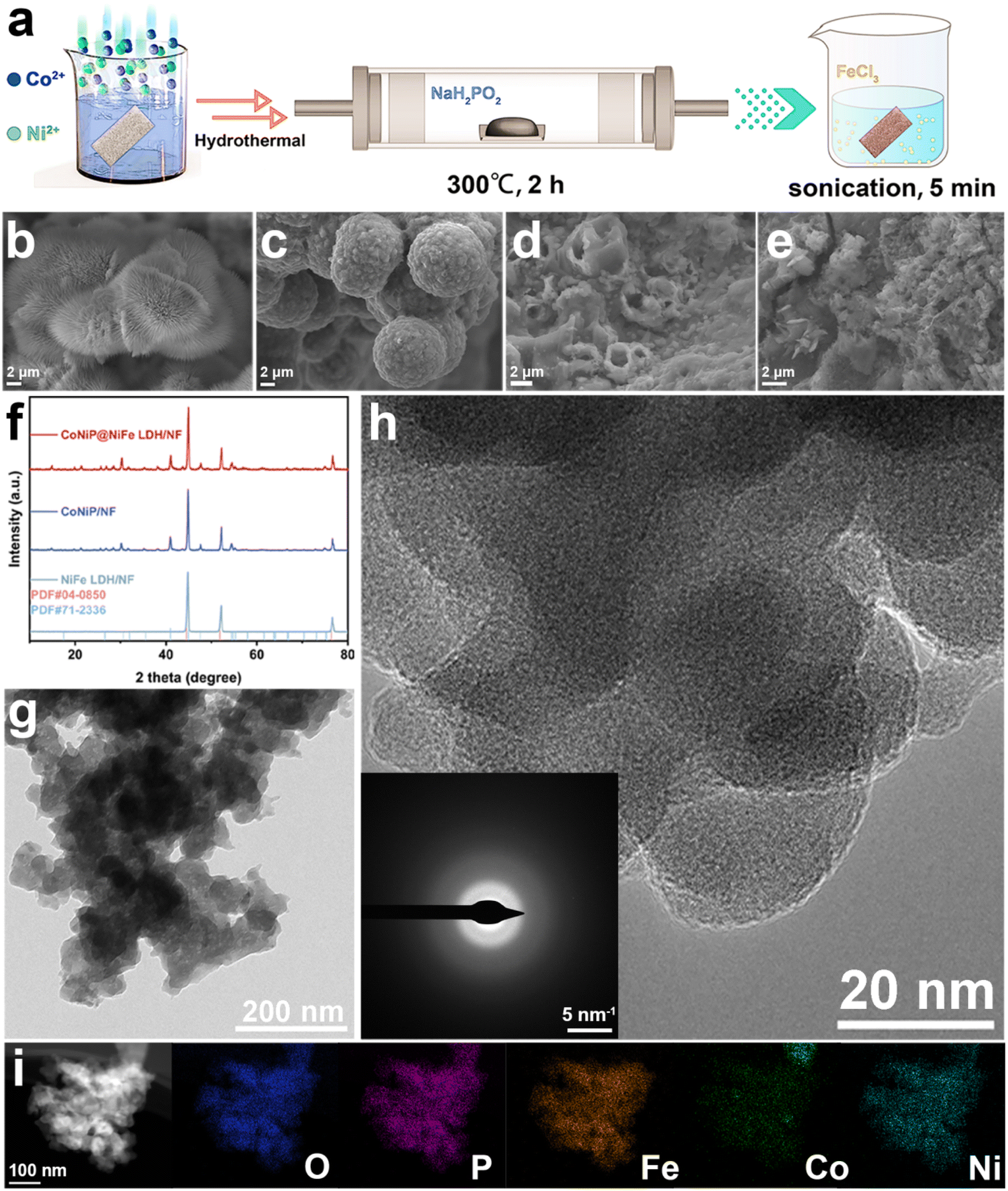 | ||
| Fig. 1 (a) Scheme of preparation, corresponding SEM of (b) CoNi-pristine/NF, (c) CoNiP/NF, (d) CoNiP@NiFe-LDH/NF, (e) NiFe-LDN/NF, (f) the XRD patterns of catalysts, (g) TEM image, (h) HR-TEM image (inset is the corresponding SAED pattern), and (i) Elemental mappings of CoNiP@NiFe-LDH/NF. | ||
Further characterization studies of CoNiP@NiFe-LDH/NF were carried out in order to demonstrate the formation of the heterogeneous structure. TEM image shows that the overall morphology is consisted of nanosheets encapsulating the particles in agreement with SEM (Fig. 1g). High resolution transmission electron microscopy (HRTEM) showed the overall material was poorly crystallized (Fig. 1h). The corresponding SAED pattern (inset in Fig. 1h) is blurred, proving an amorphous structure. The amorphous structure can provide a large number of active sites for catalytic reactions. The presence and homogeneous distribution of Fe, Co, Ni, P and O elements was confirmed using energy dispersive X-ray spectroscopy (EDX) (Fig. S2†) and elemental mappings (Fig. 1i). These mappings also prove the formation of heterogeneous structure of CoNiP@NiFe-LDH/NF.
To demonstrate the establishment of the catalyst heterostructure while detecting information about the elements and corresponding chemical states in the catalyst, CoNiP/NF, NiFe-LDH/NF and CoNiP@NiFe-LDH/NF were measured using X-ray photoelectron spectroscopy (XPS). The spectrum investigated for CoNiP/NF showed the presence of Co, Ni, P, O, and C (Fig. S3a†). While the investigated spectra of NiFe-LDH/NF and CoNiP@NiFe-LDH/NF have peaks of Cl in addition to the elements that should be present, which originate from the residual FeCI3 (Fig. S4a† and 2a). The high-resolution C 1s spectra of all samples show similar results (Fig. S3b, S4b, and S5†), which originate from the addition of signal carbon in the XPS measurements.27 The plots of all O 1s show only two peaks, OH and adsorbed water, respectively (Fig. S3c, S4c,† and 2b).28 The spectra of the details of P 2p show a doublet signal, which we attribute to the M–P bond in the sample (Fig. S3d† and 2c).29
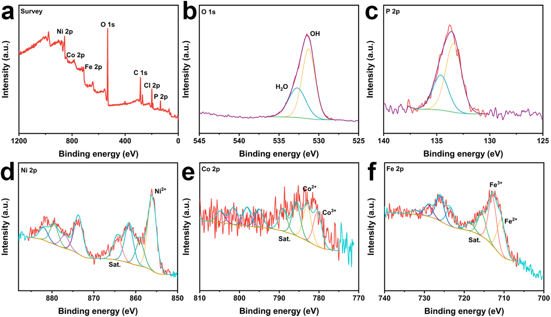 | ||
| Fig. 2 The survey spectra (a), high-resolution X-ray photoelectron spectra of (b) O 1s, (c) P 2p, (d) Ni 2p, (e) Co 2p, and (f) Ni 2p of CoNiP@NiFe-LDH/NF. | ||
The presence of Ni2+ at ∼856 eV and ∼859 eV in the Ni 2p3/2 spectra and their satellite peaks at ∼861.2 and ∼864 eV (denoted as “Sat.”).30,31 The Ni signal remained consistent for all samples, indicating that the various treatments did not affect the stability of elemental Ni (Fig. S3e, S4d,† and 2d). The peaks of Co were divided into Co3+ and Co2+ and two satellite peaks (Fig. S3f† and 2e).32–35 And the Co3+ content in CoNiP@NiFe-LDH/NF is significantly higher than that in CoNiP/NF, which indicates that the construction of heterostructures promotes more Co elements to higher valence states. In the high-resolution Fe 2p3/2 spectra (Fig. S4e† and 2f), the signal is decomposed into four peaks at ∼710.6 eV, ∼713 eV, ∼716 eV, and ∼718.8 eV, which are typical for Fe3+ and Fe2+, respectively.36,37
The XPS results also showed that elemental Fe reacted with elemental Ni to produce NiFe-LDH by immersing CoNiP in FeCl3 solution. The difference in surface charge strengths between the two components resulted in charge transfer and strong electronic interactions. It helps to modulate the electronic properties of the sample in favor of the electrocatalytic activity. Meanwhile, the high valence cobalt element produced by charge transfer facilitates the generation of intermediate products to promote the OER reaction.
The OER activities of CoNi-pristine/NF, CoNiP/NF, NiFe LDH/NF, CoNiP@NiFe LDH/NF, and NF were then evaluated in a standard three-electrode system (Table S2†). Among all catalysts, CoNiP@NiFe LDH/NF exhibited the best OER activity, requiring an overpotential of only 207 mV at 10 mA cm−2, compared to the overpotential of CoNiP/NF (217 mV), NiFe LDH/NF (297 mV), CoNi-pristine/NF (249 mV), NF (279 mV), and commercial RuO2/NF (265 mV) (Fig. 3a). The CoNiP@NiFe LDH/NF remains one of the superior groups of catalysts when compared with other reported heterojunction materials at high currents (Table S3†). The corresponding Tafel slopes were further calculated from the LSV curves to gain an understanding of the electrochemical reaction kinetics. As with the LSV results, CoNiP@NiFe LDH/NF exhibited the smallest Tafel slope (36.5 mV dec−1), proving its faster reaction kinetics (Fig. 3b). The obtained EIS data were used to analyze the charge transfer capacity of the catalyst. CoNiP@NiFe LDH/NF showed a semicircle with the smallest radius, indicating that it has the smallest charge transfer resistance (Rct) (Fig. 3c). In addition, the double-layer capacitance (Cdl) of the catalysts was calculated by cyclic voltammetry (CVs) (Fig. S6†). The CoNiP@NiFe LDH/NF has the largest Cdl (Fig. 3d), which means that it has the largest electrochemical active surface area (ECSA), indicating the largest number of electrochemical active sites. The EIS and ECSA demonstrate that the establishment of the heterogeneous structure improves the charge transfer capability of the catalyst and increased the electrochemical active sites. The stability of CoNiP@NiFe LDH/NF was then studied using the constant current density method. When run at 100 mA cm−2 for 120 h, CoNiP@NiFe LDH/NF exhibited negligible potential loss, indicating the remarkable stability of the catalyst at high current density (Fig. 3e). To further demonstrate the stability of the catalyst, we tested the change of metal content in the electrolyte before and after the reaction, and it can be seen that the change of metal content in the electrolyte is almost negligible (Fig. S7†).
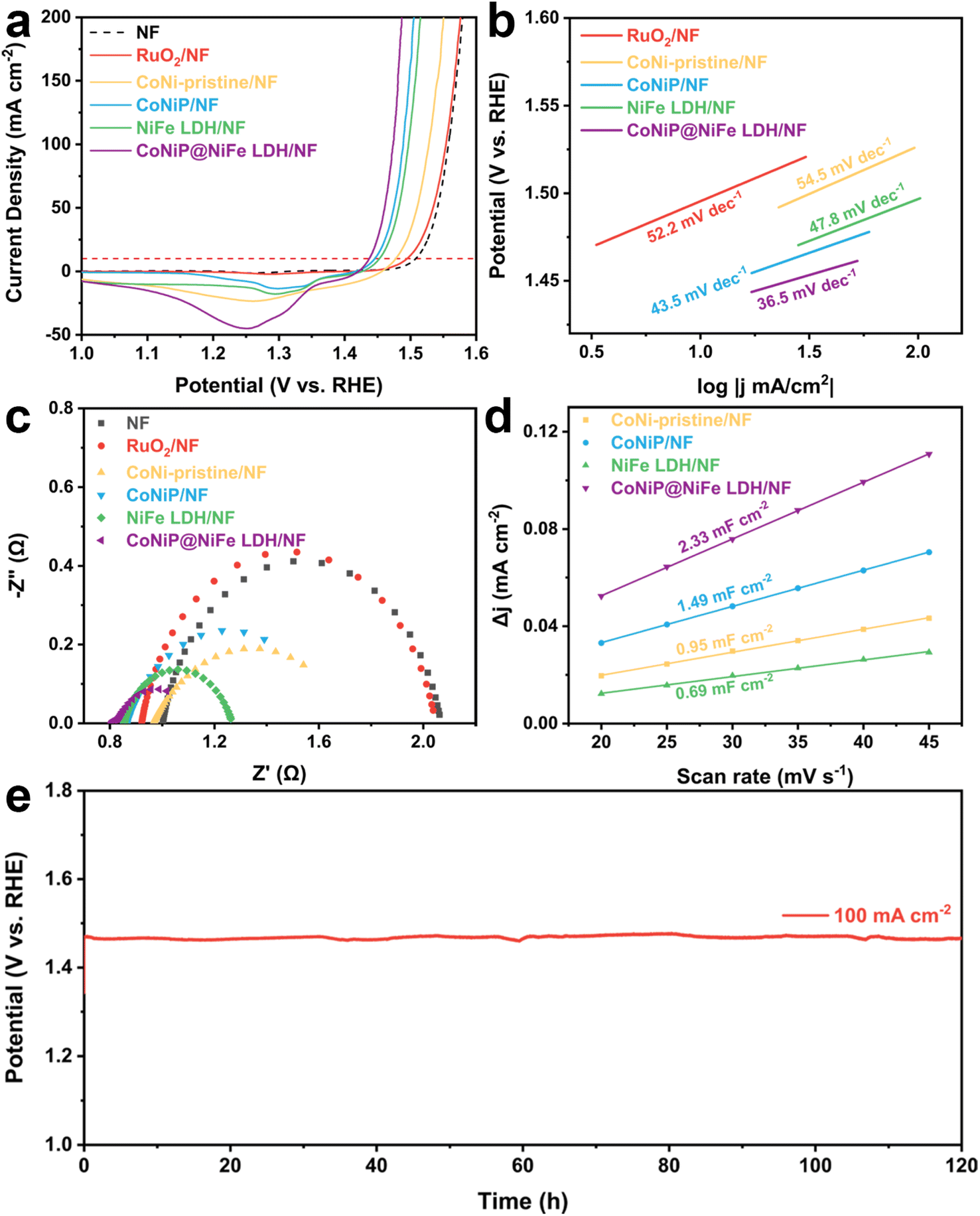 | ||
| Fig. 3 OER performances of catalysts. (a) LSV curves, (b) the corresponding Tafel slopes, (c) the Nyquist plots at 1.53 V vs. RHE, (d) the corresponding double-layer capacitance Cdl of samples, and (e) chronopotentiometry curve of CoNiP@NiFe-LDH/NF at 100 mA cm−2 in 1 M KOH. | ||
After the above discussion, we believe that the enhanced catalytic performance of CoNiP@NiFe LDH/NF is caused by the following factors. First, the self-supported three-dimensional morphology can both maximize the exposure of the active site and not disrupt the adsorption and desorption of intermediates during the reaction. Second, the formation of NiFe-LDH both increases the active site and helps the stability of the catalyst. Third, the establishment of a heterogeneous interface leads to the formation of partial charge exchange, thus increasing the catalytic activity of the sites while accelerating the reaction kinetics.
4. Conclusion
In summary, we obtained the highly efficient OER catalyst CoNiP@NiFe LDH/NF by phosphorylation and construction of heterojunctions on CoNi-pristine synthesized by a simple hydrothermal method. The heterostructure of the catalyst was confirmed by XRD, SEM, XPS and other characterization means. CoNiP@NiFe LDH/NF showed the most excellent performance in 1 M KOH with an overpotential of only 207 mV at 10 mA cm−2, which is superior to the benchmark RuO2/NF and both monomers. This excellent performance is mainly attributed to the heterostructure establishment forming more electrocatalytic active sites and promoting charge transfer capability, suitable morphology and synergistic effect of Ni(OH)2 and FeOOH advantages. This work helps to guide the rational design of heterostructures based on interface engineering for the synthesis of catalysts with high catalytic activity and stability of OER.Conflicts of interest
The authors declare that they have no known competing financial interests or personal relationships that could have appeared to influence the work reported in this paper.Acknowledgements
This work was supported by the National Natural Science Foundation of China (No. 21777090), by Research Project Supported by Shanxi Scholarship Council of China (No. 2020-010) and by a grant from Shanxi Laboratory for Yellow River (No. YRL-202110).References
- K. Yuan, S. Sfaelou, M. Qiu, D. Lützenkirchen-Hecht, X. Zhuang, Y. Chen, C. Yuan, X. Feng and U. Scherf, ACS Energy Lett., 2018, 3, 252–260 CrossRef CAS.
- X.-W. Lv, W.-W. Tian and Z.-Y. Yuan, Electrochem. Energy Rev., 2023, 6, 23 CrossRef CAS.
- K. Yuan, D. Lützenkirchen-Hecht, L. Li, L. Shuai, Y. Li, R. Cao, M. Qiu, X. Zhuang, M. K. H. Leung, Y. Chen and U. Scherf, J. Am. Chem. Soc., 2020, 142, 2404–2412 CrossRef CAS PubMed.
- M. S. Dresselhaus and I. L. Thomas, Nature, 2001, 414, 332–337 CrossRef CAS PubMed.
- J. Feng, R. Tang, G. Liu and T. Meng, Chem. Eng. J., 2023, 452, 139131 CrossRef CAS.
- N. T. Suen, S. F. Hung, Q. Quan, N. Zhang, Y. J. Xu and H. M. Chen, Chem. Soc. Rev., 2017, 46, 337–365 RSC.
- Z.-P. Wu, X. F. Lu, S.-Q. Zang and X. W. Lou, Adv. Funct. Mater., 2020, 30, 1910274 CrossRef CAS.
- K. A. Stoerzinger, R. R. Rao, X. R. Wang, W. T. Hong, C. M. Rouleau and Y. Shao-Horn, Chem, 2017, 2, 668–675 CAS.
- O. Diaz-Morales, S. Raaijman, R. Kortlever, P. J. Kooyman, T. Wezendonk, J. Gascon, W. T. Fu and M. T. M. Koper, Nat. Commun., 2016, 7, 12363 CrossRef CAS PubMed.
- X. H. Xie, L. Du, L. T. Yon, S. Y. Park, Y. Qiu, J. Sokolowski, W. Wang and Y. Y. Shao, Adv. Funct. Mater., 2022, 32, 2110036 CrossRef CAS.
- X. Lv, Z. Hu, J. Ren, Y. Liu, Z. Wang and Z.-Y. Yuan, Inorg. Chem. Front., 2019, 6, 74–81 RSC.
- Y. Feng, L. Chen and Z.-Y. Yuan, J. Ind. Eng. Chem., 2023, 120, 27–46 CrossRef CAS.
- T. Q. Guo, L. D. Li and Z. C. Wang, Adv. Energy Mater., 2022, 12, 2200827 CrossRef CAS.
- S. S. Li, Y. Q. Gao, N. Li, L. Ge, X. H. Bu and P. Y. Feng, Energy Environ. Sci., 2021, 14, 1897–1927 RSC.
- X.-W. Lv, Y. Liu, W. Tian, L. Gao and Z.-Y. Yuan, J. Energy Chem., 2020, 50, 324–331 CrossRef.
- X.-W. Lv, W.-S. Xu, W.-W. Tian, H.-Y. Wang and Z.-Y. Yuan, Small, 2021, 17, 2101856 CrossRef CAS PubMed.
- Y. K. Liu, S. Jiang, S. J. Li, L. Zhou, Z. H. Li, J. M. Li and M. F. Shao, Appl. Catal., B, 2019, 247, 107–114 CrossRef CAS.
- B. Dou, J. Yan, Q. Chen, X. Han, Q. Feng, X. Miao and P. Wang, Sens. Actuators, B, 2021, 328, 129082 CrossRef CAS.
- Q. Liu, Q. Chen, Y. Tang and H.-M. Cheng, Electrochem. Energy Rev., 2023, 6, 15 CrossRef CAS.
- Y. Feng, J.-T. Ren, H.-Y. Wang, L. Wang and Z.-Y. Yuan, Inorg. Chem. Front., 2023, 10, 4510–4518 RSC.
- Y.-l. Wang, T.-h. Yang, S. Yue, H.-b. Zheng, X.-p. Liu, P.-z. Gao, H. Qin and H.-n. Xiao, ACS Appl. Mater. Interfaces, 2023, 15, 11631–11641 CrossRef CAS PubMed.
- B. Zhong, B. Cheng, Y. B. Zhu, R. Ding, P. Y. Kuang and J. G. Yu, J. Colloid Interface Sci., 2023, 629, 846–853 CrossRef CAS PubMed.
- X. Lu and C. Zhao, Nat. Commun., 2015, 6, 6616 CrossRef CAS PubMed.
- L. Tan, J. Yu, C. Wang, H. Wang, X. Liu, H. Gao, L. Xin, D. Liu, W. Hou and T. Zhan, Adv. Funct. Mater., 2022, 32, 2200951 CrossRef CAS.
- F. Nie, Z. Li, X. P. Dai, X. L. Yin, Y. H. Gan, Z. H. Yang, B. Q. Wu, Z. T. Ren, Y. H. Cao and W. Y. Song, Chem. Eng. J., 2022, 431, 134080 CrossRef CAS.
- Y. Yang, Y. C. Xie, Z. H. Yu, S. S. Guo, M. W. Yuan, H. Q. Yao, Z. P. Liang, Y. R. Lu, T. S. Chan, C. Li, H. L. Dong and S. L. Ma, Chem. Eng. J., 2021, 419, 129512 CrossRef CAS.
- J. Lu, P. Askeland and L. T. Drzal, Polymer, 2008, 49, 1285–1296 CrossRef CAS.
- M. C. Biesinger, B. P. Payne, A. P. Grosvenor, L. W. M. Lau, A. R. Gerson and R. S. C. Smart, Appl. Surf. Sci., 2011, 257, 2717–2730 CrossRef CAS.
- S. Wenzel, D. A. Weber, T. Leichtweiss, M. R. Busche, J. Sann and J. Janek, Solid State Ionics, 2016, 286, 24–33 CrossRef CAS.
- B. Zhao, Z. Chen, Y. Chen and X. Ma, Int. J. Hydrogen Energy, 2017, 42, 27073–27083 CrossRef CAS.
- R.-P. Ye, W. Gong, Z. Sun, Q. Sheng, X. Shi, T. Wang, Y. Yao, J. J. Razink, L. Lin, Z. Zhou, H. Adidharma, J. Tang, M. Fan and Y.-G. Yao, Energy, 2019, 188, 116059 CrossRef CAS.
- X. Zhang, X. Li, R. Li, Y. Lu, S. Song and Y. Wang, Small, 2019, 15, 1903297 CrossRef CAS PubMed.
- M. Yu, K. S. Belthle, C. Tüysüz and H. Tüysüz, J. Mater. Chem. A, 2019, 7, 23130–23139 RSC.
- Y. Xu, F. Zhang, T. Sheng, T. Ye, D. Yi, Y. Yang, S. Liu, X. Wang and J. Yao, J. Mater. Chem. A, 2019, 7, 23191–23198 RSC.
- S. Liu, H. Cheng, K. Xu, H. Ding, J. Zhou, B. Liu, W. Chu, C. Wu and Y. Xie, ACS Energy Lett., 2019, 4, 423–429 CrossRef CAS.
- S. Lee, J. Y. Cheon, W. J. Lee, S. O. Kim, S. H. Joo and S. Park, Carbon, 2014, 80, 127–134 CrossRef CAS.
- R. Liu, R. Tang, J. Feng and T. Meng, Chem. Eng. J., 2023, 470, 144261 CrossRef CAS.
Footnote |
| † Electronic supplementary information (ESI) available. See DOI: https://doi.org/10.1039/d3ra05717h |
| This journal is © The Royal Society of Chemistry 2023 |