
 Open Access Article
 This Open Access Article is licensed under a Creative Commons Attribution-Non Commercial 3.0 Unported Licence
Fe-based double perovskite with Zn doping for enhanced electrochemical performance as intermediate-temperature solid oxide fuel cell cathode material†
Liang-Mei Xuea,
Song-Bo Li *a,
Sheng-Li Anb,
Ning Lia,
Hui-Pu Maa and
Meng-Xin Lia
*a,
Sheng-Li Anb,
Ning Lia,
Hui-Pu Maa and
Meng-Xin Lia
aSchool of Chemistry and Chemical Engineering, Inner Mongolia University of Science & Technology, Baotou 014010, China. E-mail: songboli2021@hotmail.com
bSchool of Material and Metallurgy, Inner Mongolia University of Science & Technology, Baotou 014010, China
First published on 18th October 2023
Abstract
This study aims to investigate the implications of transition-metal Zn doping at the B-site on the crystal structure, average thermal expansion coefficient (TEC), electrocatalytic activity, and electrochemical performance of LaBaFe2O5+δ by preparing LaBaFe2−xZnxO5+δ (x = 0, 0.05, 0.1, 0.15, 0.2, LBFZx). The X-ray diffraction (XRD) results show that Zn2+ doping does not change the crystal structure, the unit cell volume increases, and the lattice expands. The X-ray photoelectron spectroscopy (XPS) and mineral titration results show that the oxygen vacancy concentration and Fe4+ content gradually increase with the increase in doping amount. TEC decreases with the increase in Zn2+ doping amount, and the TEC of LBFZ0.2 is 11.4 × 10⁻⁶ K−1 at 30–750 °C. The conductivity has the best value of 103 S cm−1 at the doping amount of x = 0.1. The scanning electron microscopy (SEM) images demonstrate that the electrolyte CGO(Gd0.1Ce0.9O1.95) becomes denser after high-temperature calcination, and the cathode material is well attached to the electrolyte. The electrochemical impedance analysis shows that Zn2+ doping at the B-site can reduce the (Rp) polarization resistance, and the Rp value of the symmetric cell with LaBaFe1.8Zn0.2O5+δ as cathode at 800 °C is 0.014 Ω cm2. The peak power density (PPD) value of the anode-supported single cell is 453 mW cm−2, which shows excellent electrochemical performance.
1. Introduction
As an all-solid-state device, solid oxide fuel cells (SOFCs) have the advantages of high efficiency, high energy utilization efficiency, and low environmental pollution.1 The high operating temperature (∼1000 °C) of traditional SOFCs leads to problems such as thermal stress caused by mismatched connecting materials, chemical reactions between different components, sintering between electric electrodes particles, and high production costs,2 which hinder its commercial development. Therefore, this study aimed to reduce the operating cost by reducing the operating temperature of SOFCs from high temperature to medium-to-low temperature. However, with the decrease in operating temperature, the sharp increase in cathodic polarization resistance loss results in major damages to the output power of IT-SOFCs.3 Therefore, reducing polarization resistance by optimizing the cathode can effectively improve the performance of IT-SOFCs.The bi-perovskite material has high oxygen diffusion coefficient, high oxygen surface diffusion coefficient, and good electrochemical performance. The general structure formula is AA′BO5+δ (A = rare earth elements, A′ = Ba, B = Co, Cu, Fe and Mn). Considering the difference between the ion radius, rare earth ions and Ba2+ often occupy different sites, and an ordered sequence of –A′O–BO2–AOδ–BO2–A′O– is generated along the c axis.4 This regular layer structure reduces the binding energy of Ln–O bonds, and oxygen vacancies in the LnOδ layer generate independent channels of oxygen transport to moderate ion movement and promote the rapid diffusion of O2−. Cobalt-based bi-perovskite LnBaCo2O5+δ is widely used as a SOFC cathode because of its excellent conductivity and oxygen transport properties. However, considering the high TEC usually in the range of 20–25 × 10−6 K−1, Co-based bi-perovskite peroxides do not match the commonly used electrolytes at the operating temperature, resulting in high interface stress and output performance degradation.5 Fe-based bi-perovskite peroxides show promising application prospects because of their low cost, good thermal compatibility, and high-temperature stability. The current research work mainly focuses on LaFeO3, BaFeO3, SrFeO3, and LnBaFe2O5+δ.6–8 The transition metal ion Fe has variable oxidation state and spin state, which may have high catalytic activity.9 In addition, partial substitution of alkaline earth elements, rare earth elements or iron sites is used to optimize the initial structure and create more oxygen vacancies, thereby promoting oxygen transport.10–13 The partial substitution of LaFeO3 with perovskite structure at A and B sites, such as La0.6Sr0.4Fe0.8Cu0.2O3−δ and La0.6Ca0.4Fe0.8Ni0.2O3−δ, showed that the catalytic activity of oxygen reduction reaction (ORR) and electrochemical performance were significantly improved after substitution.14,15
B-site transition metal ions have various valence changes, and B-site doping can adjust the ion valence directly in order to change the crystal structure, affect the oxygen ion diffusion ability, and improve the catalytic activity. Given the effect of charge compensation, low-valence Zn2+ can promote the formation of holes and oxygen vacancies, thereby regulating the mixed oxygen ion and electronic characteristics of LaBaFeO5+δ. Therefore, appropriate Zn2+ doping can effectively improve the electrocatalytic activity of Fe-based bi-perovskite peroxides and make them serve as high-performance cathodes for SOFC. Therefore, in this paper, LaBaFe2−xZnxO5+δ (x = 0, 0.05, 0.1, 0.15, 0.2, LBFZx) series materials were synthesized, and the effects of Zn2+ doping on the physical and chemical properties were studied. The electrochemical performance of LBFZx as the cathode of IT-SOFC was tested by preparing a symmetrical cell and an anode-supported single cell.
2. Experimental
2.1 Preparation
LaBaFe2−xZnxO5+δ (x = 0, 0.05, 0.1, 0.15, 0.2, LBFZx) series cathode powders were prepared using the sol–gel method. La(NO3)3·6H2O(AR), Ba(NO3)2(AR), Fe(NO3)2·9H2O(AR), and Zn(NO3)2·3H2O(AR) were weighed according to the stoichiometric ratio calculation. An appropriate amount of deionized water and the raw materials were stirred and dissolved in the beaker, then EDTA dissolved in ammonia was added and stirred continuously. Citric acid was added to the above solution after 1 h (nctric acid![[thin space (1/6-em)]](https://www.rsc.org/images/entities/char_2009.gif) :nmetal ions:nEDTA = 1.5:1:1), and the pH value of the solution was adjusted to 8 by using an appropriate amount of ammonia. Then, the sample was placed in a water bath at 80 °C until a gel was formed. The gel was heated until it spontaneously combusted to form a fluffy black precursor. After the precursor was calcined at 1100 °C for 5 h, the target cathode powder was obtained. According to the different Zn contents, the materials with Zn doping were named as LBFZx (x = 0, 0.05, 0.1, 0.15, and 0.2).
:nmetal ions:nEDTA = 1.5:1:1), and the pH value of the solution was adjusted to 8 by using an appropriate amount of ammonia. Then, the sample was placed in a water bath at 80 °C until a gel was formed. The gel was heated until it spontaneously combusted to form a fluffy black precursor. After the precursor was calcined at 1100 °C for 5 h, the target cathode powder was obtained. According to the different Zn contents, the materials with Zn doping were named as LBFZx (x = 0, 0.05, 0.1, 0.15, and 0.2).
2.2 Cell fabrication
The cathode paste was evenly coated on both sides of the CGO electrolyte through screen printing, and then dried and calcined at 1100 °C for 5 h to make a symmetrical cell. The silver paste and wire were used as current collector.The anode and fluppy CGO electrolyte powder were evenly spread in a circular mold with a diameter of 15 mm, and then dry-pressed at a pressure of 200 MPa to obtain a half cell brick. The brick was calcined at 1450 °C for 5 h to obtain the half cell. The slurry made of cathode material was uniformly coated on the half cell (electrolyte CGO side) through screen printing, and the single cell was obtained finally.
2.3 Characterization
The phase structures of the prepared cathode materials were analyzed using an X-ray diffractometer (XRD, Malvern Panalytical B. V.) at a scan rate of 5° min−1 in the range of 10°–80°, and the results were Rietveld finished using the GSAS/EXPGUI software. The variation in the oxygen content of samples in air from 30 °C to 750 °C at a rate of 5 °C min−1 was analyzed by thermogravimetry (NETZSCH, STA2500). The valence states of surface elements in the LBFZx sample were analyzed using XPS (Thermo Scientific, EscaLab250Xi). The average TEC of sintered cathode strips was measured using a thermal dilatometer (NETZSCH, DIL 402C) at 30–750 °C in air atmosphere. The UV-vis absorption spectra were measured by UV-vis-NIR-scanning spectrophotometer (UV-3101PC). The lattice spacing was characterized as well using transmission electron microscopy (TEM, JEOL-2100F). Electrochemical workstation (Metrohm, PGSTAT302) was used to test the conductivity of the material in the range of 200°–800 °C, and the electrochemical impedance spectrum (EIS) of the symmetrical cell was obtained. The test frequency range was 0.1 Hz to 100 kHz, and the AC signal amplitude was 10 mV. In addition, the output power of a single cell was tested in the range of 650–800 °C at 50 °C intervals. Through scanning electron microscopy (SEM, TESCAN, GAIA3), the cross sections of symmetrical cells and single cells after performance testing were observed.3. Results and discussion
Fig. 1(a) shows the XRD pattern of LBFZx (x = 0, 0.05, 0.1, 0.15, 0.2) obtained by calcinating the samples at 1100 °C in air for 5 h. The figure indicates the absence of impurity phase, indicating that LBFZx is a pure phase with double perovskite structure,16 and the local area is magnified as shown in Fig. 1(b). The XRD diffraction peak of LBFZx gradually shifts to low angle with the increase in Zn2+ doping, indicating that the unit cell volume of LBFZx gradually increases and the lattice expands. The crystal structure of LBFZx was further determined by refining the XRD patterns of LBFZx by using the GSAS software (Fig. 1(c) and S1†), which showed a good match between the refined results and the XRD patterns. The results of LBFZx are listed in Table S1,† in which the unit cell parameters of LBFZx gradually increased with the increase in doping amount, and the lattice expanded, because the radius of Zn2+ (0.74 Å) is larger than that of Fe3+/4+ (Fe3+ ∼0.65 Å, Fe4+ ∼0.0.585 Å).17 The results show that the fabricated LBFZx has the same structure as the undoped LBF, indicating that the doping of Zn2+ does not change the original crystal structure. Considering the large difference between the ionic radius of Ba and La, cations are arranged in the alternate layer of –BaO–FeZnO2–LaOδ–FeZnO2–BaO– along the C axis, as shown in Fig. 1(d). Oxygen vacancies are mainly formed and migrate in the LaOδ layer. For MIEC peroxide materials, oxygen vacancies play an important role in the process of complex electrochemical reactions and directly affect the output performance of batteries.4 Fig. 1(e) shows the EDS diagram of LBFZ0.1 cathode powder attached to CGO electrolyte, which confirms that Zn successfully replaced Fe at site B, La, Ba, Fe, Zn, and O are evenly distributed, and no element aggregation occurred. Good chemical compatibility between cathode and electrolyte is crucial for the practical application of SOFC. The TEM images of the sample LBFZ0.1 is shown in Fig. 1(f), where the lattice spacing is calculated to be 3.945 Å corresponding to the (100) crystallographic plane, in agreement with the refinement results. The excessive reaction between electrode and electrolyte may form a new phase and an insulating layer, leading to a significant decline in the electrochemical performance of the battery during long-term operation.18 Therefore, the prepared LBFZ0.1 sample and electrolyte (CGO) powder were pressed at a mass ratio of 1:1 and sintered at 1100 °C for 5 h. The XRD data of the mixture is shown in Fig. S2,† showing no significant shift of diffraction peaks and no new phase formation during high-temperature heating. Hence, LBFZ0.1 has good high-temperature chemical compatibility with the electrolyte CGO. HT-XRD tests were performed on the samples under air atmosphere to evaluate the thermal stability of the Zn2+ doped materials, as shown in Fig. 1(g), there is no obvious shift of the diffraction peaks of the samples within 200–800 °C and no heterogeneous phase is generated, which indicates that the doped samples have good thermal stability.
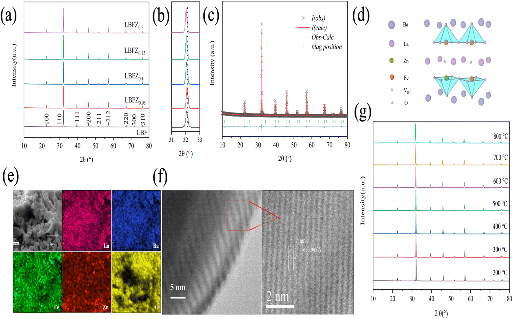 | ||
| Fig. 1 (a) XRD pattern of cathode material LBFZx; (b) partial magnification; (c) Rietveld refined pattern of LBFZ0.1 sample; (d) crystal structure of LBFZ0.1; (e) EDS diagram of LBFZ0.1 material (f) HRTEM of the LBFZ0.1; (g) high temperature XRD patterns of LBFZ0.1l. | ||
The results of iodine titration showed that the non-stoichiometric ratio of oxygen in the material decreased with the increase in doping amount (Table S2†). Combined with the analysis of TGA data, Fig. 2(a) shows the variation curve of oxygen content in the cathode powder of LBFZx (x = 0, 0.05, 0.1, 0.15, 0.2) with the temperature in air. The oxygen content of the sample remained unchanged with the increase in temperature, and a similar phenomenon has been reported in the literature.19 This finding was obtained, possibly because the oxygen ion was frozen in the crystal lattice at low temperature. With the further increase in temperature, the oxygen content of the sample gradually decreased, which may be related to the release of lattice oxygen caused by heat.17 With the increase in doping amount, the oxygen content of the sample gradually decreased, indicating that more oxygen vacancies can be generated. Generally, the increase of oxygen vacancy concentration is beneficial to improve the transport and migration of oxygen ions in the ORR, improve the catalytic reaction activity, and thus promote the electrochemical performance of the cathode material. Fig. 2(b) shows that with the increase in Zn2+ doping amount, the average valence state of b-site element gradually decreases, and the average valence state of Fe gradually increases, indicating that Fe is oxidized to a higher valence state and coexists with +3 and +4 valence in LBFZx.
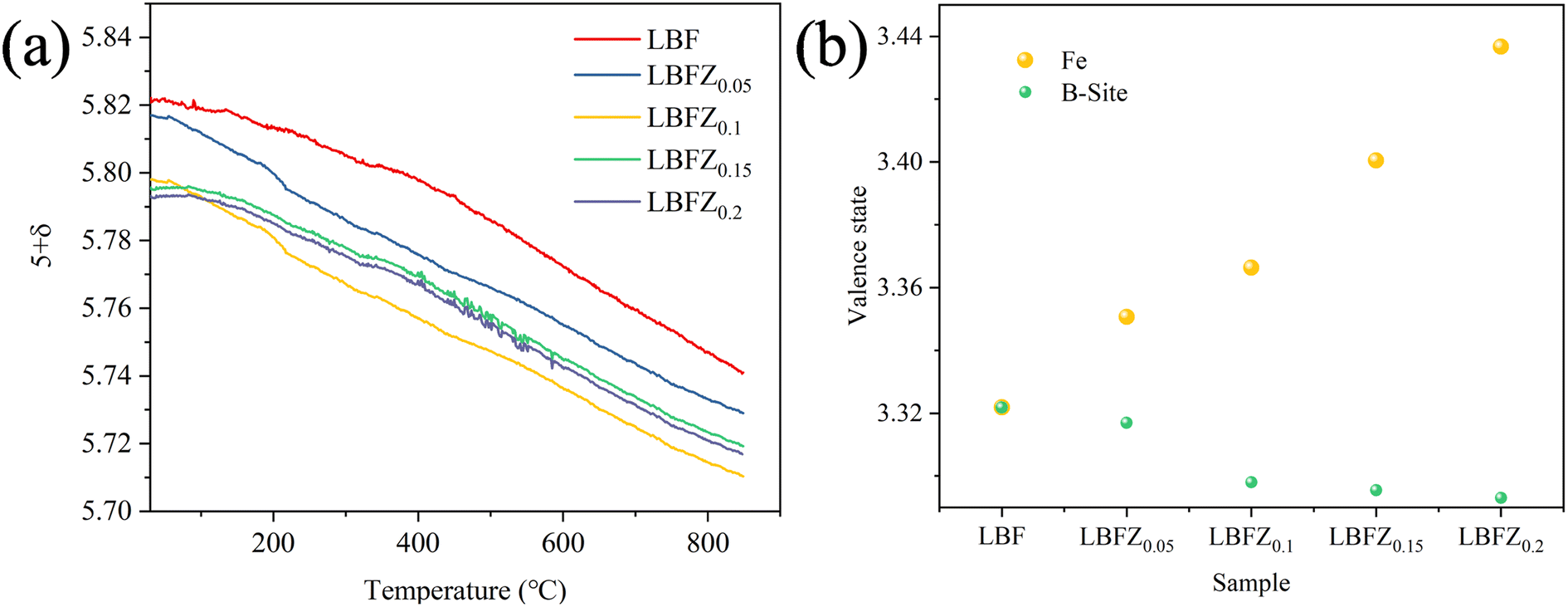 | ||
| Fig. 2 (a) Variation curve of oxygen content (5 + δ) of LBFZx with temperature under air atmosphere; (b) average valence of Fe and B-site elements. | ||
The surface ion states of LBFZx series materials were analyzed by XPS to study the influence of Zn2+ doping on the chemical valence states of LBFZx materials. All XPS curves were calibrated based on the baseline C 1s (284.6 eV) peak. The quantitative analysis results show that Zn2+ doping reduces the oxygen content of the material and generates additional oxygen vacancies, which can also be confirmed by XPS characterization. As shown in Fig. 3(a), the high-resolution map of O 1s can fit four different characteristic peaks, indicating the existence of different types of oxygen species.20 The peak located at 528.35 eV (±0.2 eV) can be attributed to lattice oxygen (Olattice), the peak located at 531.12 eV (±0.18 eV) corresponds to adsorbed oxygen (Oadsorbed), and the peaks located at 529.3 eV (±0.2 eV) belongs to vacant oxygen (Ovacancy) and 532.11 eV (±0.2 eV) belongs to water oxygen (Omoisture), respectively. The ratio of (Oadsorbed + Ovacancy) to Olattice is listed in Table S3.† Its value increases with the increase in doping amount, indicating that the doping of Zn2+ at the B site can obtain more oxygen vacancies and active centers of oxygen adsorption/dissociation. Fig. 3(b) shows the XPS high-resolution pattern of the LBFZx Fe2p at room temperature. The spin-orbitals of Fe2p split into Fe2p1/2 and Fe2p3/2, possessing different valence states. The binding energies of 709.45 eV (±0.15 eV), 711.1 eV (±0.13 eV), 722.4 eV (±0.2 eV), and 724.0 eV (±0.2 eV) correspond to Fe3+ 2p3/2, Fe4+ 2p3/2, Fe3+ 2p1/2, and Fe4+ 2p1/2, respectively.21,22 The percentage values of Fe3+ and Fe4+ are listed in Table S3.† With the increase in Zn2+ doping amount, the proportion of Fe4+ gradually increased, indicating that the incorporation of Zn2+ results in the oxidation of the transition metal element (Fe) in the double perovskite to a higher valence state.
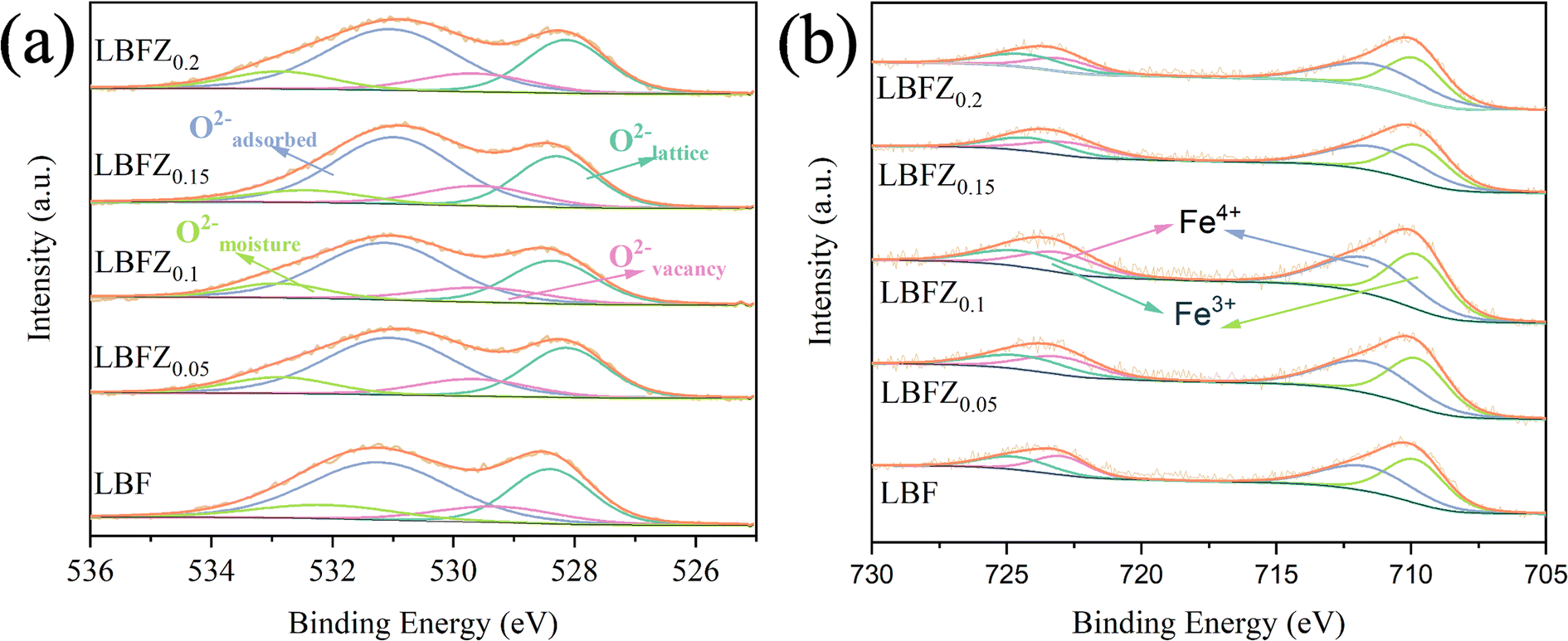 | ||
| Fig. 3 XPS curve of LBFZx (a) O 1s; (b) Fe2p. | ||
Fig. 4 shows the total conductivity (σ) of LBFZx measured in dry air by using the DC four-electrode method versus temperature. Given that the oxygen ion conductivity of perovskite structure oxide is several orders of magnitude smaller than the electron conductivity, the apparent conductivity is the electron conductivity.23 With the increase in the doping amount, the conductivity first increases and then decreases. In the perovskite structure cathode material, charge carriers are conducted by B–O–B network structure.24,25 The doping valence of Zn2+ is relatively low. The charge neutrality of LBF is maintained by increasing the Fe4+ content. As shown in eqn (1), the increase in charge carrier concentration increases the conductivity, where  and
and  represent Fe4+ and Fe3+, respectively.
 | (1) |
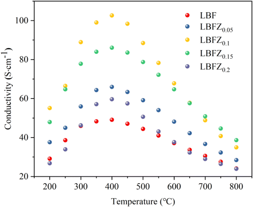 | ||
| Fig. 4 Conductivity of LBFZx in air atmosphere. | ||
However, when the doping amount is more than 0.1, the conductivity gradually decreases, because the fixed valence of the cation cannot provide the jumping point of the small polaron. At the same time, the position of Fe is replaced by Zn2+, and the sites available for the small polaron jumping are reduced. The results of iodometry showed that with the increase in Zn2+ doping, the non-stoichiometric ratio of oxygen gradually decreased, indicating that additional oxygen vacancies are generated, as shown in eqn (2). 
 and
and  represent Fe3+, lattice oxygen, and oxygen vacancy, respectively.
 | (2) |
However, the formation of a large number of oxygen vacancies and the presence of too much fixed valence Zn2+ have some adverse effects on the small polarization conduction in Fe4+–O–Fe3+ bonds. In summary, the conductivity of LBFZ0.15 and LBFZ0.2 cathode materials decreases with the increase in Zn2+ doping.
Thermal expansion mismatch can lead to the formation of cracks between the interface of cathode and electrolyte, which can affect the performance and long-term stability of the fuel cell. Therefore, the TEC of LBFZx was measured to evaluate their thermal matching performance. Fig. 5 shows the thermal expansion curve of LBFZx measured in the temperature range of 30–750 °C under air atmosphere. The influence of dL/L0 on temperature is not completely linear, and the inflection point was observed at approximately 300 °C, which may be related to the loss of lattice oxygen.26 The average TEC value of LBFZx (x = 0, 0.05, 0.1, 0.15, 0.2) in the temperature range of 30–750 °C was calculated, and the results are listed in Table S4.† LBFZ0.2 showed the lowest TEC value of 11.4 × 10⁻⁶ K−1. Zn doping decreased the TEC and improved the thermal matching with the electrolyte.
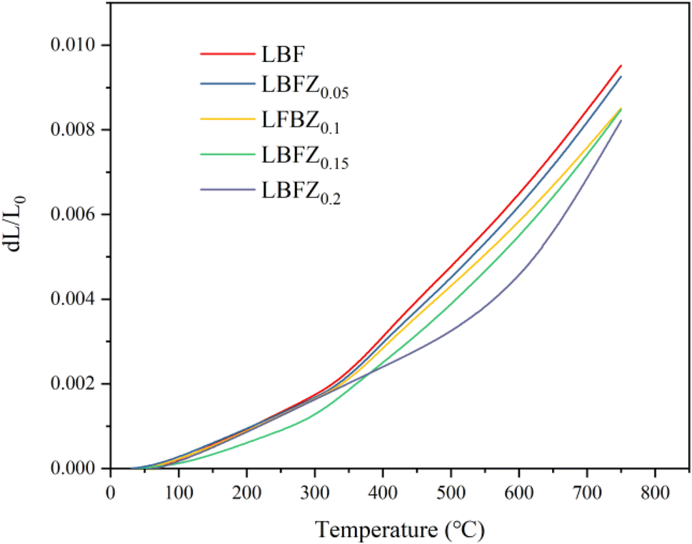 | ||
| Fig. 5 Thermal expansion curve of LBFZx in air atmosphere. | ||
The UV-vis absorption spectrum of the sample is presented in the provided Fig. 6. The band gap energy (Eg) can be determined using the Tauc equation, which is as follows:
| (αhν)1/n = A(hν − Eg) | (3) |
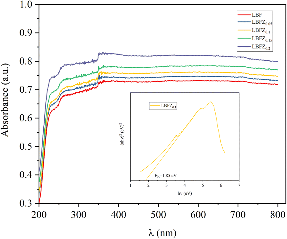 | ||
| Fig. 6 UV-vis absorption spectrum of samples LBFZx. | ||
The effect of Zn2+ doping on the LaBaFe2−xZnxO5+δ electrochemical properties was investigated by testing the AC impedance diagram of the symmetric cell LBFZx|CGO|LBFZx at 600–800 °C. Fig. 7(a) shows the AC impedance diagram of LBFZ0.2|CGO|LBFZ0.2 at different temperatures. Considering the multi-step process of ORR, the equivalent circuit Rs (RHF//CPEHF RMF//CPEMF RLF//CPELF) was used to fit the measured AC impedance diagram, where Rs is the ohmic resistance due to the electrolyte as well as the current collector. RHF, RMF and RLF represent the high-frequency, middle-frequency, and low-frequency resistance, respectively.17 Rp is the polarization resistance value (Rp = RHF + RMF + RLF). The effect of Zn2+ doping on the cathodic polarization resistance was further analyzed by zeroing the ohmic resistance.31,32 Fig. 7(a) shows that the Rp value gradually decreases with the increase in test temperature, possibly because the adsorption and dissociation speed of oxygen and the migration speed of oxygen ions in the cathode and electrolyte were gradually accelerated with the increase in temperature. This process accelerated the ORR and led to a significant decrease in the polarization resistance of the cathode with the increase in temperature. Therefore, the electrocatalytic activity of the cathode material increases with the increase in temperature.33 Fig. 7(b) demonstrates the Nyquist graph for LBFZx|CGO|LBFZx at 800 °C. The introduction of Zn2+ resulted in the decline in the polarization resistance of LaBaFe2O5+δ. The Rp values of the symmetrical cell LBFZx|CGO|LBFZx (x = 0, 0.05, 0.1, 0.15, 0.2) obtained by fitting in the range of 600–800 °C are shown in Fig. 7(c). The Rp value of LBFZ0.2 measured at 800 °C is 0.014 Ω cm2, which is approximately 65% lower than the Rp value of LBF at the same temperature (0.04 Ω cm2), and lower than those of other Fe-based cathode materials (Table 1). Therefore, Zn2+ doping improves the electrochemical performance of Fe-based double perovskite LaBaFe2O5+δ materials, because the Zn substitution of Fe at the B site reduces the oxygen content of the material and forms additional oxygen vacancies. This process promotes the oxygen adsorption and dissociation of oxygen molecules into oxygen ions, thus improving the surface oxygen exchange and diffusion of oxygen ions. The formation of extra oxygen vacancies is conducive to the oxygen reduction reaction on the electrode surface and the electrode|electrolyte interface and promotes the transport of oxygen ions in the cathode material.34 In addition, the activation energy decreased from 195.6 kJ mol−1 to 92.6 kJ mol−1 after doping with Zn2+, as shown in Fig. 7(d). This finding indicates that the LBFZ0.2 sample has great potential as a highly reactive oxygen electrode. Fig. S4† shows the SEM photo of symmetric cell section LBFZx|CGO, in which the cathode materials have a porous structure, which will be conducive to the diffusion of the gas, oxygen ion transport, and charge transfer. In addition, the good adhesion of CGO electrolyte on cathode material without obvious cracking and delamination proves that the electrode and electrolyte have good chemical compatibility and thermal matching.
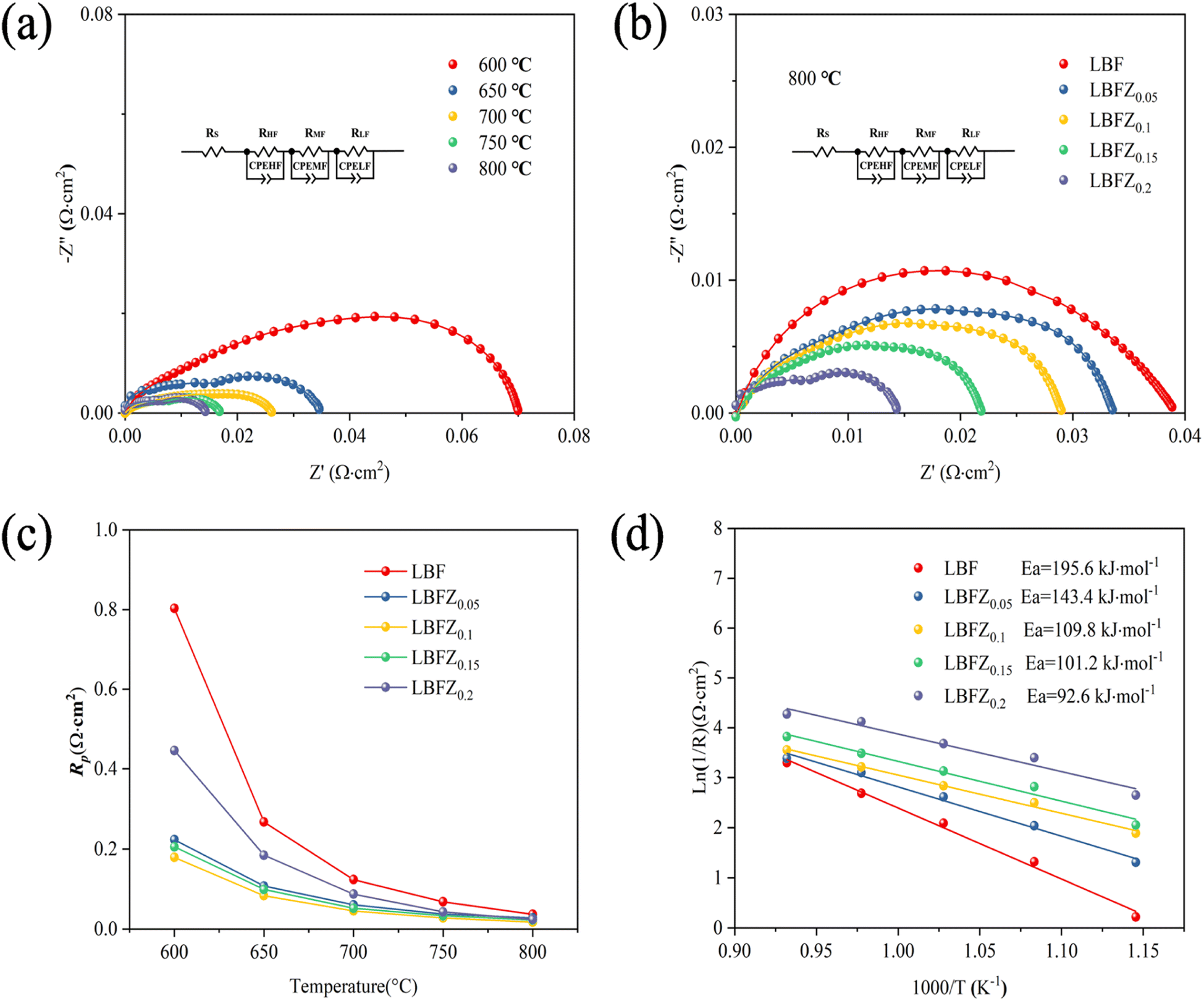 | ||
| Fig. 7 (a) Nyquist diagram of LBFZ0.2|CGO|LBFZ0.2 in the range of 600–800 °C; (b) Nyquist diagram of LBFZx|CGO|LBFZx at 800 °C; (c) Rp of LBFZx in the range of 600–800 °C; (d) Arrhenius diagram of LBFZx in the range of 600–800 °C. | ||
The effectiveness of LBFZx as cathode in the output performance of SOFC was assessed by preparing the single cell with anode support. Fig. 8(a) shows the section SEM picture of LBFZ0.1|CGO|NiO + CGO single cell after output test, in which the compact electrolyte layer was formed after the high-temperature sintering. This process ensures the high open circuit voltage (OCV) and avoids short circuit. However, Ce4+ → Ce3+ leads to the increase in the electronic conductivity of the electrolyte under high temperature, so the OCV gradually decreases with the increase of temperature.39,40 Fig. 8(b) and (c) shows the I–V–P curve of the single cell LBFZx|CGO|NiO + CGO (x = 0, 0.1) with the anode as the support and CGO as the electrolyte at 600–800 °C. Wet H2 was added as the fuel gas, and the PPD values are shown in Fig. 8(d). At 800 °C, the PPD of single cell LBFZ0.1|CGO|NiO + CGO PPD is 453 mW cm−2. In comparison with the non-optimized LBF, the output was improved by approximately 11%. This performance improvement is related to the lower polarization resistance based on LBFZ0.1 cathode.
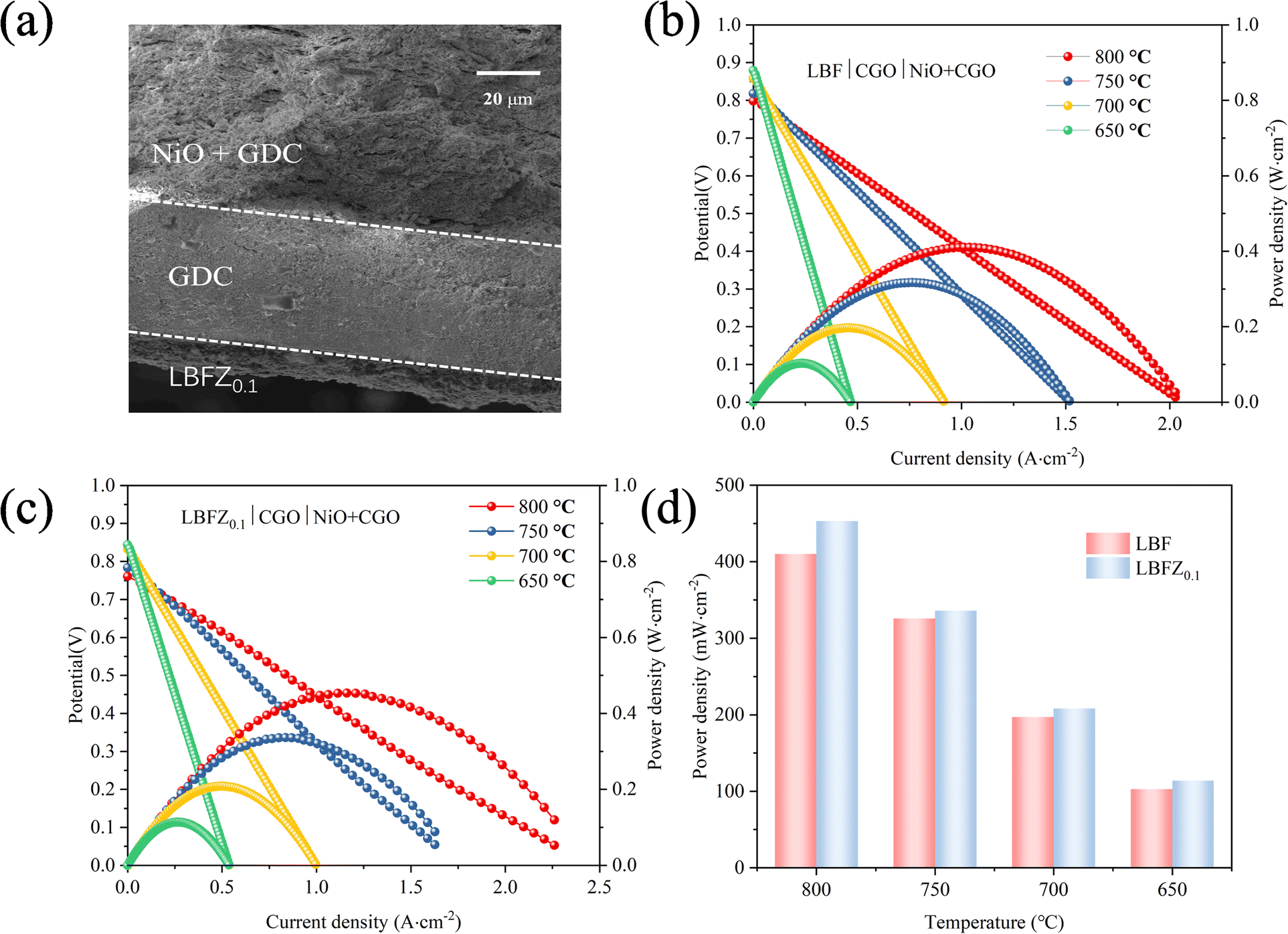 | ||
| Fig. 8 (a) SEM of LBFZ0.1|CGO|NiO + CGO single cell section (b) I–V–P curve of LBF|CGO|NiO + CGO (c) I–V–P curve of LBFZ0.1|CGO|NiO + CGO (d) PPD of single cell at different temperature. | ||
4. Conclusion
Zn2+ doping did not change the original crystal structure. Combined with Rietveld results, the unit cell parameters gradually increased, and the crystal lattice expanded with the increase in doping amount. The material has good chemical compatibility with the electrolyte CGO. The oxygen vacancy concentration and Fe4+ content gradually increased, whereas the average TEC gradually decreased with the increase in doping amount. The TEC value of LBFZ0.2 was 11.4 × 10⁻⁶ K−1 at the temperature range of 30–750 °C. The polarization resistance of the symmetric cell LBFZ0.2|CGO|LBFZ0.2 was 0.014 Ω cm2. When the optimal doping amount was 0.1, the conductivity reached 103 S cm−1. With the increase in doping concentration, the conductivity decreased gradually, showing that the formation of a large number of additional oxygen vacancy can reduce electrical conductivity. The PPD of the single cell LBFZ0.1|CGO|NiO + CGO was 453 mW cm−2, and the output performance of LaBaFe1.9Zn0.1O5+δ was improved by approximately 11% compared with the unoptimized LaBaFe2O5+δ, indicating that LaBaFe1.9Zn0.1O5+ is a promising material for IT-SOFC cathode.Conflicts of interest
There are no conflicts to declare.Acknowledgements
The work was supported by the National Natural Science Foundation of China (No. 51974167) and Scientific Research Program of Inner Mongolia Higher Education Institutions (NJZZ22449).References
- A. Lanzini, P. Leone, C. Guerra, F. Smeacetto, N. P. Brandon and M. Santarelli, Chem. Eng. J., 2013, 220, 254–263 CrossRef CAS.
- L. Bi, S. Boulfrad and E. Traversa, Solid State Ionics, 2015, 275, 101–105 CrossRef CAS.
- J. W. Zhu, S. B. Guo, Z. Y. Chu and W. Q. Jin, J. Mater. Chem. A, 2015, 3, 22564–22573 RSC.
- M. Z. Ahmad, S. H. Ahmad, R. S. Chen, A. F. Ismail, R. Hazan and N. A. Baharuddin, Int. J. Hydrogen Energy, 2022, 47, 1103–1120 CrossRef CAS.
- Y. Zhang, B. Chen, D. Q. Guan, M. G. Xu, R. Ran, M. Ni, W. Zhou, R. O'hayre and Z. P. Shao, Nature, 2021, 591, 246–251 CrossRef CAS PubMed.
- S. P. Simner, J. R. Bonnett, N. L. Canfield, K. D. Meinhardt, J. P. Shelton, V. L. Sprenkle and J. W. Stevenson, J. Power Sources, 2003, 113, 1–10 CrossRef CAS.
- B. Wei, Z. Lu, X. Q. Huang, M. L. Liu, N. Li and W. H. Su, J. Power Sources, 2008, 176, 1–8 CrossRef CAS.
- D. J. Chen, F. C. Wang, H. G. Shi, R. Ran and Z. P. Shao, Electrochim. Acta, 2012, 78, 466–474 CrossRef CAS.
- Y. Teraoka, H. Shimokawa, C. Y. Kang, H. Kusaba and K. Sasaki, Solid State Ionics, 2006, 177, 2245–2248 CrossRef CAS.
- A. Wedig, R. Merkle, B. Stuhlhofer, H. U. Habermeier, J. Maier and E. Heifets, Phys. Chem. Chem. Phys., 2011, 13, 16530–16533 RSC.
- D. Baek, A. Kamegawa and H. Takamura, Solid State Ionics, 2014, 262, 691–695 CrossRef CAS.
- F. F. Dong, Y. B. Chen, R. Ran, D. J. Chen, M. O. Tade, S. M. Liu and Z. P. Shao, J. Mater. Chem. A, 2013, 1, 9781–9791 RSC.
- S. Yoo, T. H. Lim, J. Shin and G. Kim, J. Power Sources, 2013, 226, 1–7 CrossRef CAS.
- J. Lu, Y. M. Yin, J. C. Li, L. Xu and Z. F. Ma, Electrochem. Commun., 2015, 61, 18–22 CrossRef CAS.
- N. Ortiz-Vitoriano, I. R. De Larramendi, J. I. R. De Larramendi, M. I. Arriortua and T. Rojo, J. Power Sources, 2009, 192, 63–69 CrossRef CAS.
- H. Li, B. Wei, C. X. Su, C. Q. Wang and Z. Lu, J. Power Sources, 2020, 453, 2275–2278 Search PubMed.
- R. Z. Ren, Z. H. Wang, X. G. Meng, C. M. Xu, J. S. Quo, W. Sun and K. N. Sun, ACS Appl. Mater. Interfaces, 2020, 12, 23959–23967 CrossRef CAS PubMed.
- Y. Lu, H. L. Zhao, X. W. Chang, X. F. Du, K. Li, Y. H. Ma, S. Yi, Z. H. Du, K. Zheng and K. Swierczek, J. Mater. Chem. A, 2016, 4, 10454–10466 RSC.
- W. H. Jia, Z. N. Huang, W. Sun, L. Wu, L. Zheng, Y. Q. Wang, J. B. Huang, X. Yang, M. Lv and L. Ge, J. Power Sources, 2021, 490, 22956–22964 CrossRef.
- C. Lim, Y. Yang, Y. W. Sin, S. Choi and G. Kim, Energy Fuels, 2020, 34, 11458–11463 CrossRef CAS.
- F. J. Jin, H. W. Xu, W. Long, Y. Shen and T. M. He, J. Power Sources, 2013, 243, 10–18 CrossRef CAS.
- Y. F. Zheng, Q. S. Li, T. Chen, C. Xu and W. G. Wang, J. Power Sources, 2015, 274, 736–740 CrossRef CAS.
- Y. G. Wang, J. W. Ren, Y. Q. Wang, F. Y. Zhang, X. H. Liu, Y. Guo and G. Z. Lu, J. Phys. Chem. C, 2008, 112, 15293–15298 CrossRef CAS.
- A. Niemczyk, A. Olszewska, Z. H. Du, Z. J. Zhang, K. Swierczek and H. L. Zhao, Int. J. Hydrogen Energy, 2018, 43, 15492–15504 CrossRef CAS.
- A. Subardi, K. Y. Liao and Y. P. Fu, J. Eur. Ceram. Soc., 2019, 39, 30–40 CrossRef CAS.
- N. A. Baharuddin, A. Muchtar and M. R. Somalu, Int. J. Hydrogen Energy, 2017, 42, 9149–9155 CrossRef CAS.
- A. O. Turky, M. M. Rashad, A. M. Hassan, E. M. Elnaggar and M. J. Bechelanyd, Phys. Chem. Chem. Phys., 2017, 19(9), 6878–6886 RSC.
- M. Anwar, A. S. Muhammed, A. Muchtar and M. R. Somalu, Ceram. Int., 2019, 45(5), 5627–5636 CrossRef CAS.
- R. Roy and A. Dutta, J. Alloys Compd., 2020, 843, 1–40 CrossRef.
- S. K. Alla, K. E. V. Prasadarao, R. K. Mandal and N. K. Prasad, J. Mater. Chem. Phys., 2016, 182, 280–286 CrossRef CAS.
- G. D. Li, Y. J. Gou, X. J. Cheng, Z. Bai, R. Z. Ren, C. M. Xu, J. S. Qiao, W. Sun, Z. H. Wang and K. N. Sun, ACS Appl. Mater. Interfaces, 2021, 13, 34282–34291 CrossRef CAS PubMed.
- T. Chen, S. L. Pang, X. Q. Shen, X. N. Jiang and W. Z. Wang, RSC Adv., 2016, 6, 13829–13836 RSC.
- J. C. Ruiz-Morales, J. Canales-Vazquez, J. Pena-Martinez, D. Marrero-Lopez and P. Nunez, Electrochim. Acta, 2006, 52, 278–284 CrossRef CAS.
- S. B. Adler, Chem. Rev., 2004, 104, 4791–4843 CrossRef CAS PubMed.
- Z. P. He, L. N. Xia, Y. H. Chen, J. C. Yu, X. W. Huang and Y. Yu, RSC Adv., 2015, 5, 57592–57598 RSC.
- T. Hong, M. Y. Zhao, K. Brinkman, F. L. Chen and C. R. Xia, ACS Appl. Mater. Interfaces, 2017, 9, 8659–8668 CrossRef CAS PubMed.
- G. L. Xiao, Q. A. Liu, F. Zhao, L. Zhang, C. R. Xia and F. L. Chen, J. Electrochem. Soc., 2011, 158, B455–B460 CrossRef CAS.
- Q. J. Zhou, L. L. Zhang and T. M. He, Electrochem. Commun., 2010, 12, 285–287 CrossRef CAS.
- T. Y. Guan, Y. Sun, Z. Q. Yang, Y. H. Jing and W. F. Guo, Ceram. Int., 2019, 45, 23355–23363 CrossRef CAS.
- H. G. Shi, C. Su, R. Ran, J. F. Cao and Z. P. Shao, Prog. Nat. Sci.: Mater. Int., 2020, 30, 764–774 CrossRef CAS.
Footnote |
| † Electronic supplementary information (ESI) available. See DOI: https://doi.org/10.1039/d3ra04991d |
| This journal is © The Royal Society of Chemistry 2023 |