DOI:
10.1039/D3RA04110G
(Review Article)
RSC Adv., 2023,
13, 24393-24411
Research progress on MOFs and their derivatives as promising and efficient electrode materials for electrocatalytic hydrogen production from water
Received
19th June 2023
, Accepted 24th July 2023
First published on 14th August 2023
Abstract
Hydrogen energy is considered to be the most potential “ultimate energy source” due to its high combustion calorific value, cleanliness, and pollution-free characteristics. Furthermore, the production of hydrogen via the electrolysis of water has the advantages of simplicity, high efficiency, environmentally safe, and high-purity hydrogen. However, it is also associated with issues such as high-power consumption for the reaction and limited large-scale application of noble metal catalysts. Metal–organic frameworks (MOFs) are porous composite materials composed of metal ions and organic functional groups through orderly coordination with large specific surface areas and large porosity. Herein, we focus on the research status of MOFs and their transition metal derivatives for electrocatalytic water splitting to produce hydrogen and briefly describe the reaction mechanism and evaluation parameters of the electrocatalytic hydrogen evolution and oxygen evolution reactions. Furthermore, the relationship between the catalytic behavior and catalytic activity of different MOF-based catalysts and their morphology, elemental composition, and synthetic strategy is analyzed and discussed. The reasons for the excellent activity and poor stability of the original MOF materials for the electrolysis of water reaction are shown through analysis, and using various means to improve the catalytic activity by changing the electronic structure, active sites, and charge transfer rate, MOF-based catalysts were obtained. Finally, we present perspectives on the future development of MOFs for the electrocatalytic decomposition of water.
1 Introduction
The search for alternative energy sources to alleviate the energy and environmental crises caused by fossil fuels has led to a focus on the development of clean and sustainable renewable energy and its conversion, transport and storage technologies.1–3 In this case, hydrogen energy has the advantages of high energy density, recyclability, and zero carbon emissions, making it a perfect substitute for fossil fuels.4 Since the 19th century, researchers have been exploring various hydrogen energy conversion technologies and their application for large-scale industrial production. At present, the mainstream strategies for the industrial production of hydrogen include reforming fossil fuels,5 coke oven gas chemical production,6 reforming methanol/methane7,8 and water electrolysis.9 However, although various hydrogen production methods including methanol reforming have advantages in terms of production cost, they are accompanied by the production of CO2.10 In contrast, water electrolysis is clean and non-polluting hydrogen production technology, which has the advantages of high hydrogen production efficiency and high purity, but has the problem of high production cost.
Water electrolysis involves two half-reactions, the hydrogen evolution reaction (HER) and oxygen evolution reaction (OER). Compared with the HER, the OER is a four-electron transfer process. Consequently, the slow kinetics and large overpotential of the OER need to be overcome for the electrochemical reaction of water electrolysis, which inhibits the industrial application of hydrogen production from water electrolysis.11 Therefore, the rational design of electrocatalysts is necessary to lower the reaction energy barriers of the HER and OER. In this case, noble metal-based materials with high catalytic activity, electrical conductivity, and stability are considered to be the most effective catalysts for electrocatalytic water splitting. However, due to the low abundance and high cost of precious metal elements, they cannot solve the fundamental problem of hydrogen production technology by the electrolysis of water.12 Therefore, the development of non-precious metal materials to replace noble metal catalysts is of great significance for the commercialization of hydrogen production from water electrolysis.
Thus far, through research on non-noble metal catalysts, it has been found that transition metal element-based catalysts such as Fe, Ni, and Co not only have high reserves in the Earth and low cost, but also outstanding electrocatalytic performance in water splitting reactions.13 The factors influencing high-efficiency electrocatalytic materials have been determined from the study of various catalysts, including large specific surface area, high porosity, uniform distribution of active sites, and high charge transfer ability.14 These factors play an important role in maximizing the electron transfer and facilitating the mass transport of reactants. Therefore, they can be tuned to improve the electrocatalytic performance of materials. For example, porous scaffold structures are formed to reduce the overpotential,15 active sites are added to accelerate electron conduction and proton transfer,16 and the electronic structure of the catalyst is adjusted to improve its intrinsic activity by alloying,17 defect engineering,18 interfacial coupling,19 and formation of a heterostructure.20 Based on these methods, we aim to explore electrolytic water catalysts with lower cost, higher catalytic activity, and stability.
Metal–organic frameworks (MOFs) are a new type of lattice porous structure crystals connected by organic linkers and metal ions through coordination bonds, which have structural advantages such as large specific surface area and high porosity. To date, numerous MOFs have been discovered, which have been applied in different fields according to their structural properties, such as gas adsorption,21 sensors,22 catalysis,23 and drug delivery.24 MOFs have the characteristics of homogeneous and heterogeneous catalysts, which can be directly applied in the field of electrocatalysis. Owing to their high surface area, rich pore structure, diverse composition, and well-defined metal centers, fast mass transfer and a high density of active sites can be achieved for enhanced catalytic performances.25 To improve the catalytic activity of MOFs and the stability of the catalytic process, MOFs can be used as templates after the heat treatment of various types of alloys, metal oxides, metal sulfides, metal carbides, and metal phosphide under different conditions, resulting in very strong electric catalytic performances.26 These MOF derivatives retain the original porous structure and other properties of their parent MOF and have a high number of active sites, high electrical conductivity, and high stability.
In recent years, through the selection of suitable metal ion centers and functional ligands, a large number of derivative catalysts composed of specifically designed and fabricated nanostructured materials has emerged. Herein, we focus on different strategies to enhance the electrocatalytic performance of MOF-based materials and briefly summarize the reaction mechanism of water electrolysis HER and OER, the evaluation parameters of the electrocatalysts, and different synthetic design methods for MOF materials. Given the wide range of research on MOF-based materials, we only present the recent research on MOF-based materials as electrocatalysts. Finally, we prospect the main challenges associated with MOF-based materials in electrocatalysis.
2 Mechanisms and parameters
2.1 Hydrogen evolution reaction mechanism
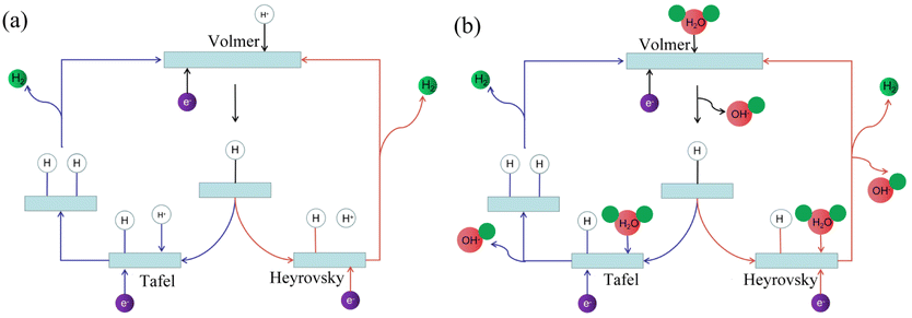
The hydrogen evolution reaction (HER) in electrolyzed water involves multi-step elementary reactions.27 A schematic diagram of the hydrogen evolution reaction is shown in Fig. 1. The first step is the Volmer reaction.28 The protons/water molecules in the electrolyte combine with the free electrons on the electrode surface to form adsorbed hydrogen atoms on the catalyst surface. Subsequently, one of two steps occurs as the catalytic properties of materials vary.29 The hydrogen atoms in the first adsorption state combine in pairs to generate hydrogen gas, which is the Tafel reaction. Alternatively, the hydrogen atoms in the second adsorption state continue to combine with protons/water molecules in the electrolyte to generate hydrogen gas, which is the Heyrovsky reaction.
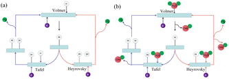 |
| | Fig. 1 Hydrogen evolution reaction mechanism. (a) Schematic diagram of hydrogen evolution reaction in acidic solution. (b) Schematic diagram of hydrogen evolution reaction in alkaline solution. | |
The reaction formula under acidic conditions is as follows (eqn (1)–(3)):
| | |
Volmer: M + H+ + e− → Hads + M
| (1) |
| | |
Tafel: Hads + Hads → H2
| (2) |
| | |
Heyrovsky: Hads + H+ + e− → H2
| (3) |
The reaction formula under alkaline conditions is as follows (eqn (4)–(6)):
| | |
Volmer: M + H2O + e− → Hads + OH− + M
| (4) |
| | |
Tafel: Hads + Hads → H2
| (5) |
| | |
Heyrovsky: Hads + H2O + e− → H2 + OH−
| (6) |
where M is the catalyst, H
ads is the hydrogen atom in the adsorption state, and
b is the Tafel slope, which is an important kinetic parameter in the water electrolysis reaction.
2.2 Oxygen evolution reaction mechanism
The kinetics of the oxygen evolution reaction is slow, which is the key factor restricting the overall electrolysis water reaction.30 In general, the oxygen evolution reaction mechanism is the conventional adsorption mechanism for the four-electron transfer process (adsorbate evolution mechanism, AEM). This is the adsorption and desorption process of intermediates in the conversion process of OHads → Oads → OOHads → O2ads.11 Specifically, in this process, water molecules and hydroxyl ions are used as the reactants in acidic and alkaline media, continuously oxidized to OHads, Oads, and OOHads, and finally oxidized to oxygen molecules. The mechanism under acidic conditions is as follows:| | |
M + H2O → MOH + H+ + e−
| (7) |
| | |
MOH + OH− → MO + H2O + e−
| (8) |
| | |
MO + H2O → MOOH + H+ + e−
| (10) |
| | |
MOOH + H2O → M + O2 + H+ + e−
| (11) |
The mechanism under alkaline conditions is as follows:
| | |
MOH + OH− → MO + H2O
| (13) |
| | |
MO + OH− → MOOH + e−
| (15) |
| | |
MOOH + OH− → M + O2 + H2O
| (16) |
However, with the continuous development of various oxygen evolution catalysts, it has been gradually found that some catalysts have other mechanisms in the oxygen evolution reaction. Therefore, researchers proposed the lattice oxygen evolution mechanism (lattice oxygen-mediated mechanism, LOM) to fully explain this phenomenon (Fig. 2).31,32 When the solid phase oxide/hydroxide with high metal–oxygen covalent bond properties undergoes the oxygen evolution reaction, the lattice oxygen of the catalyst itself tends to be oxidized under the OER potential and participates in the OER reaction to generate oxygen.33
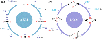 |
| | Fig. 2 Oxygen evolution reaction mechanism. (a) Traditional adsorption evolution mechanism. (b) Lattice oxygen precipitation mechanism. | |
2.3 Free energy of hydrogen adsorption
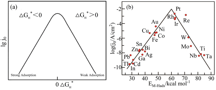
According to the analysis of the above-mentioned hydrogen evolution reaction mechanism, the chemical adsorption and desorption of protons in the electrolyte on the electrode surface are competitive processes.34 According to the Sabatier principle,35 an ideal hydrogen evolution catalyst with high catalytic performance and catalytic efficiency should form moderately strong and weak chemical bonds with the adsorbed Hads. This can speed up the proton–electron transfer process and make the chemical bonds easy to break and generate gaseous H2. Density function theory (DFT) was used to calculate the free energy change (ΔGH*) value of Hads adsorption on the catalyst surface.36 Fig. 3(a) presents a graph of the relationship between the exchange current density and the hydrogen adsorption energy depicted under the Langmuir adsorption model, where ΔGH* can be used to interpret the degree of adsorption of Hads and the degree of H2 desorption through the HER free energy diagram. Based on the study of different metals as HER electrodes, the relationship between the exchange current density of hydrogen and the chemical adsorption energy of each metal hydrogen is summarized in Fig. 3(b).37
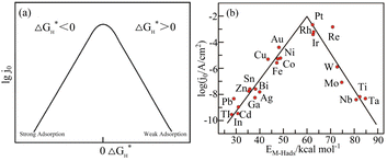 |
| | Fig. 3 Hydrogen adsorption free energy correlation curve. (a) Langmuir adsorption model diagram. Reproduced from ref. 34 with permission from John Wiley and Sons, Copyright 2014. (b) HER volcano curve diagram on a metal electrode in an acidic medium. Reproduced from ref. 37 with permission from the American Chemical Society, Copyright 2010. | |
2.4 Tafel slope and exchange current density
The Tafel slope and exchange current density are two closely related important kinetic parameters in the field of electrochemistry. To study the quantitative relationship between the overpotential and the exchange current density, Tafel proposed the Tafel electrochemical equation, which reveals the kinetics of electrocatalytic reactions, as follows:| |
η = a + b![[thin space (1/6-em)]](https://www.rsc.org/images/entities/char_2009.gif) logj logj
| (17) |
where η is the overpotential, a is a constant, b is the Tafel slope, and j is the current density. The Tafel slope is an important parameter to reveal the reaction mechanism. According to the size of the Tafel slope, the kinetic rate of the electrocatalyst and the rate-determining steps of the reaction can be determined.38 When the Tafel slope is small, the charge transfer rate is fast, and thus the reaction overpotential is small under the same current density and the rate-determining step of the reaction is the end of the electron transfer reaction. On the contrary, when it is large, the charge transfer rate is slow and the reaction overpotential is large under the same current density, and the rate-determining step of the reaction is the initial step of electron transfer. The exchange current density j0 is the corresponding current density when the electrode reaction is balanced. When the exchange current density of the electrocatalytic reaction is larger, the electrocatalytic activity of the catalyst is higher.
2.5 Overpotential
The overpotential is an important parameter to evaluate the electrocatalytic performance of catalysts.39 Specifically, it is the potential difference between the thermodynamically determined equilibrium potential for the hydrogen evolution or oxygen evolution half-reaction and the actual potential that drives the electrolytic water half-reaction. In the current research on the electrolytic water reaction, there are mainly three types of overpotentials, i.e., activation overpotential, concentration overpotential, and resistance overpotential.40 Generally, the overpotential at the current density of 10 mA cm−2 is used as the standard to determine the electrocatalytic performance of a catalyst.41 Under the same current density, the smaller the overpotential, the higher the catalytic performance.
2.6 Stability
Stability is a prerequisite for determining whether an electrocatalyst can be used in actual production. At present, there are three common stability testing methods in the field of electrochemistry, i.e., linear sweep voltammetry (LSV) and chronoamperometry/potential method.42 The voltage is repeated periodically during the LSV method test, and the magnitude of the change in the polarization curve after a large number of cycles indicates the stability of the electrocatalyst, where a catalyst with strong stability remains almost unchanged after the test. The principle of chronoamperometry is to measure the curve of the current as a function of time for 24 h, while keeping the applied voltage between the working electrode and reference electrode constant. The stability of the catalyst can be judged by observing the coincidence of the curves, while the chrono-voltaic trend is the opposite.
2.7 Turnover frequency
The turnover frequency (TOF) is defined as the number of catalytic reactions or target products generated on the active site per unit time. By definition, the numerical value of the TOF can reflect the intrinsic activity of a catalyst.43 Therefore, it has an important reference value in evaluating the electrocatalytic activity of catalysts. The TOF can be calculated using the following formula:| | |
TOF = (J × A)/(α × N × F)
| (18) |
where J is the current density (mA cm−2) at a given overpotential, which can be obtained from the LSV curve. A is the surface area of the electrode (mm2), α is the number of transferred electrons corresponding to the formation of one molecule of the target product, F is the Faraday constant (96485C mol−1), and N is the number of catalyst active sites (mol). However, determining the number N of catalyst active sites existing on the electrode surface is a key problem in accurately obtaining the TOF value of a catalyst. Although there are many methods to calculate the number of active sites, such as redox integration, UPD, and stripping voltammetry, there is no specific method for the calculation of the number of active sites in heterogeneous electrocatalytic reactions.44 In this case, the method adopted by many researchers assuming that 100% of the catalyst participates in the reaction underestimates the real TOF value, but it still has a certain reference value.45
2.8 Electrochemical impedance spectroscopy
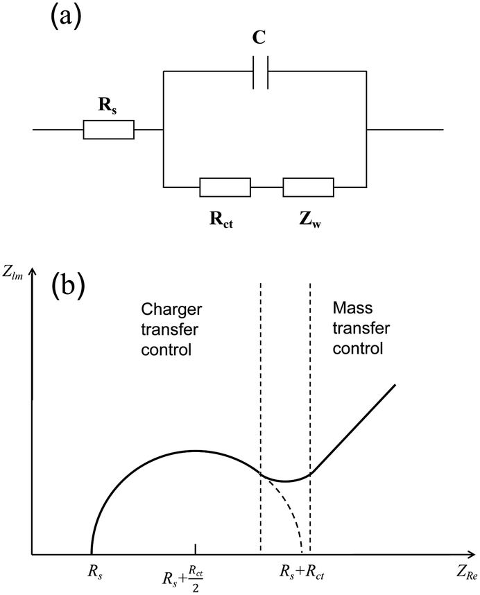
Electrochemical impedance spectroscopy (EIS) is an electrochemical measurement method that applies a small-amplitude sine wave electrical signal as interference.46 In electrochemical impedance spectroscopy, the Nyquist plot is commonly used as a means to evaluate the performance of electrocatalysts. An abstract circuit diagram of the electrochemical reaction can be constructed according to the typical electrochemical reaction (Fig. 4). The three electrochemical components are the internal resistance, Rs, of the electrolyte and the electrode, the electric double layer capacitance, C, and the Faraday impedance, Zf. The Faraday impedance, Zf, is equivalent to the charge transfer resistance, Rct, and Warburg impedance, Zw. The Nyquist diagram shows a sloping straight line in the low-frequency region, but in the high-frequency region, material transfer does not occur in time, and thus it presents a semi-circular curve. The size of the diameter reflecting the charge transfer resistance can be obtained by fitting the high-frequency region, which can be used as an important parameter to evaluate the catalytic performance of electrocatalysts.
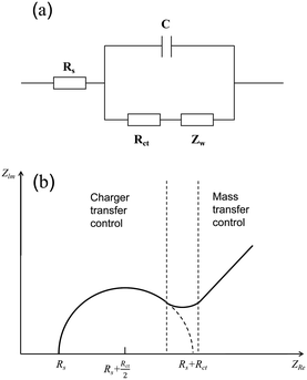 |
| | Fig. 4 Schematic of electrochemical impedance. (a) Equivalent circuit diagram of electrolysis water reaction. (b) Nyquist curve analysis diagram. | |
2.9 Electrochemically active surface area
To evaluate the real activity of catalysts, the concept of electrochemically active surface area (ECSA) was proposed by analysing the surface area of a catalyst that participates in electrochemical reactions on the electrode surface.47 Presently, the electrochemical active surface area testing methods are mainly divided into the following categories: use of specific Faraday reactions such as HUPD, metal underpotential deposition, etc.; redox peak area integration; CV method to test Cdl in Faraday; AFM atomic force microscopy test; and BET test to approximate the size of the ECSA. The calculation of the electrochemically active surface area using the electric double-layer capacitance is the most common test method, which can be calculated using the following formula:where Cs is the specific capacitance of the catalyst. In general, a larger ECSA facilitates the adsorption of water molecules and intermediates, thereby enhancing the contact with the electrolyte and providing more active centres for electrocatalytic reactions.48
2.10 Area-specific activity and mass-specific activity
Area-specific activity and mass-specific activity are two activity parameters that can be employed to evaluate the inherent performance of catalysts.49 The area-specific activity is the current density normalized by the electrochemically active surface area of the electrocatalyst. Given that the electrochemically active area is related to the actual number of active sites on the electrode surface, the area-specific activity is similar to the TOF and can reflect the intrinsic activity of the catalyst. The mass-specific activity is the current density normalized by the loaded mass of the electrocatalyst. The definition of mass activity assumes that all the atoms in each particle are electrocatalytically active sites. However, in the case of surface chemical processes, reactions only occur at/near the surface, and electrode materials usually have better bulk structural stability, and thus their mass activity does not represent their intrinsic activity. Furthermore, the mass activity strongly depends on the particle size of the reactive surface atomic fraction. Particles of smaller size exhibit higher mass activity due to their larger ratio of surface atoms to total atoms per unit mass.
2.11 Faraday efficiency
Faradaic efficiency refers to the percentage of actual formation and theoretical formation. It is considered to be the ratio between the experimental and theoretical hydrogen production in the water electrolysis reaction. In practical applications, the faradaic efficiency is an important parameter to evaluate the electrocatalytic performance of catalysts. The experimental hydrogen production can be measured by gas chromatography or the conventional drainage method, while the theoretical hydrogen production can be calculated by the integration of galvanostatic or potentiostatic electrolysis.
3 MOFs and their derivatives
3.1 Research status of MOFs
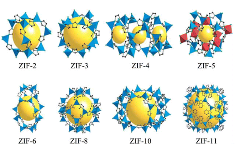
In the mid-1990s, Yaghi first proposed the concept of MOFs in an article published in Nature.50 The structures of the ZIF series materials synthesized by a research group are shown in Fig. 5.51 MOFs are composed of metal ions and organic functional groups through ordered coordination.52 MOFs not only have a larger specific surface area than traditional porous materials but also the advantages of adjustable pore size, large porosity, etc., showing considerable application prospects in various areas. In the field of catalysis, using the mesoporous caged NH2-MIL-101 as a precursor, the Fe SAC-MIL101-T catalyst with rich accessible FeNx single atomic sites exhibited excellent oxygen reduction activity through steps such as pyrolysis at different temperatures and durability.53 It had a high peak power density of 192.3 mW cm−2 and excellent energy density of up to 984.2 W h kgZn−1 for aqueous Zn–air batteries. MOF-808-CuNi converted from Cu/Ni DMSP made key progress in the photocatalytic reduction of CO2 to improve the CH4 conversion and activity.54 The electron selectivity reached 99.4%, the product selectivity was 97.5%, and its activity was as high as 158.7 μmol g−1 h−1. MOFs can also be used as adsorbents for CO2 capture. An MOF, Calgary Framework 20, had high adsorption capacity and CO2/N2 adsorption selectivity for CO2.55 It had strong stability for steam or wet acid gas, even in the flue gas of natural gas combustion for a long time. In terms of adsorbing pollutants in water, CMC/MOF/PEP three-dimensional porous aerogel materials were successfully synthesized by loading polypeptides on cellulose/metal–organic framework composites (CMC/MOF).56 They showed a good adsorption performance for perfluorooctanoic acid in water, with the adsorption capacity reaching 27 mg g−1, which have practical application value. A breakthrough was made in the study of MOFs for C2H2/CO2 gas separation, where the super-strong B based on relatively adjacent open metal sites in MOFs showed a strong binding interaction with C2H2.57 Record C2H2/CO2 selectivity was achieved in C2H2/CO2 mixtures at 298 K and 1 bar. This made MOFs a new benchmark material for C2H2/CO2 separation. The pollution of PM particles in the atmosphere is a serious hazard to human health. Therefore, a PLA air filter membrane produced by mechanically poling ZIF-8 crystals (PLA@ZIF8) grown on the surface of PLA fibers was reported.58 The P-PLA@ZIF8-6 fiber membrane had a filtration efficiency of 88% for PM 0.3 at a flow rate of 10 L min−1, which was significantly improved compared with that of the PLA fiber membrane. Alternatively, the storage problem of hydrogen has promoted the research on gas storage materials. Through the study of crystal shape and size characteristics of different MOFs,59 it was demonstrated that the strategy for the design of the crystal size and crystal morphology of MOF-5 greatly improves its volumetric hydrogen storage performance, which can exceed the 25 g L−1 volume and DOE volume target capacity (30 g L−1) of a typical 700 bar compressed storage system. The stability and degradation properties of MOFs in liquid media determine their use in biomedicine. Compared with the widely used antimicrobial agent ZnO, the zinc-based MOF ZIF-8 exhibited excellent antibacterial properties.60 It had a larger zone of inhibition, lower MBC value in PBS, and higher bactericidal effect in LB. In the aspect of cancer therapy, ICG-CpG@MOF, which used specific MOFs (MIL101-NH2) as the core carrier and was doubly modified with a fluorescence signal donor (ICG) and immune adjuvant (CpG) under photoacoustic conditions, could be passive targeted to tumor sites through the EPR effect and achieved multi-modal imaging of tumors.61 This strategy utilizing multimodal imaging and synergistic cancer photoimmunotherapy provided an effective strategy for cancer diagnosis and treatment. Molecularly imprinted electrochemical sensors based on nanomaterials/nanocomposites have been widely used for the analysis of pesticides. New molecularly imprinted electrochemical sensors based on Co3O4 nanowires and core–shell Co3O4@MOF-74 nanocomposites were applied for the detection of pesticides.62 The sensor showed a sensitive detection limit of 1.0 × 10⁻¹¹ M and a highly selective signal, which provided a detection method for pesticide analysis with selectivity and sensitivity. The application of MOFs in energy storage has been widely researched. Homogeneous MXene/MOF composites prepared by co-precipitation reaction were further transformed by ion conversion-exchange into hollow Ti3C2Tx/ZIF-67/CoV2O6 composites.63 Their specific capacitance of 285.5 F g−1 has opened new avenues for the design and synthesis of MXene/MOF composites and complex hollow structures.
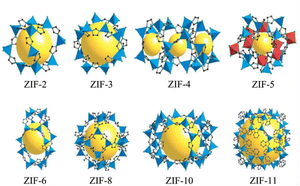 |
| | Fig. 5 Schematic diagram of the structure of ZIF series materials. Reproduced from ref. 44 with permission from National Academy of Sciences, Copyright 2006. | |
3.2 Methods for the preparation of MOFs
The reported methods for the preparation of MOFs were mainly divided into the conventional solution method,64 diffusion method,65 solvothermal method,66 microwave method,67 ion thermal synthesis method,68 and mechanochemical synthesis method.69 The conventional solution method refers to the method of reacting in a specific solution at a certain temperature. The diffusion method involves reacting at the contact interface of two mutually insoluble substances.70 In this case, the reaction conditions are mild but the reaction time is long. The solvothermal method, also known as the hydrothermal method, refers to intermolecular contact and reaction under higher temperatures or steam conditions. This method requires simple equipment and produces a relatively high product yield but requires the large consumption of organic solvents. The microwave method involves ultrasonically dissolving metal substances in organic solvents, and then performing microwave heating reactions in a microwave. Microwaves can accelerate the nucleation rate of MOF crystals, and the synthesis time is extremely short. The ion thermal synthesis method uses an ionic liquid as both the solvent and template to participate in the synthesis of MOF materials. Compared with common organic solvents, ionic liquids will affect the structure of the product due to their structure and hydrophilicity, thereby improving the yield and structure regulation of MOF materials. Mechanochemical synthesis involves grinding and extruding substances to use mechanical energy to change their physical and chemical properties, and then undergo chemical reactions. This method is environmentally friendly, takes a short time, and has a high yield, but it is difficult to detect the presence of impurities. In addition to the above-mentioned common synthesis methods, other synthesis methods have been reported, such as co-crystallization,71 deposition, and electrochemical methods.72 Therefore, different methods should be selected for different MOF materials according to the materials and conditions required for their synthesis.
3.3 MOF derivatives
Although MOFs have rapidly developed in various fields such as adsorption and gas storage, due to their limited catalytic activity, thermal stability, and stability in chemical reactions, MOF materials cannot be used in large-scale electrocatalysis. Thus, to improve the stability and electrocatalytic performance of MOFs, researchers explored their structure. By using MOFs as template materials, MOF-derived materials were produced under high-temperature and high-pressure conditions. The resulting materials not only inherit the characteristics of super-large specific surface area, multi-porosity, and other structural features of MOFs, but also have a simple preparation method, more material diversity, and solve the more important problem of material stability. Therefore, they have been widely used in the fields of batteries,73 supercapacitors,74 sensors,75 adsorption76 and electrocatalytic reactions.77 The common classifications of MOF derivatives used as electrocatalytic water decomposition catalysts are metals,78 alloys,79 transition metal carbides,80 transition metal oxides,81 transition metal sulfides,82 transition metal phosphides83 and single-atom catalysts.84
4 Direct use of MOFs as catalysts for electrolysis of water
As organic–inorganic porous composite materials, MOFs can be customized by different metal ions or organic ligands. Compared with other electrolytic water catalysts such as non-porous nanoparticles, the porous nature and large specific surface area of MOFs can provide more active sites for catalytic reactions.85 The synergistic effect between the metal elements and carbon and nitrogen elements in the organic ligands of MOFs also greatly promotes their electrocatalytic activity. These characteristics of MOFs determine their inherent advantages in homogeneous and heterogeneous catalytic reactions. As electrocatalysts, they can often reduce the overpotential, accelerate the reaction kinetics, and ensure energy conversion efficiency. This determines the absolute potential of MOFs as electrocatalysts. Recently, many MOF-based materials have been reported as HER and OER catalysts, which are presented in Tables 1 and 2, respectively.
Table 1 A summary of the timeline of pristine MOF and MOF transition metal derivatives for electrocatalytic HER
| Year |
Catalyst |
Substrate |
Electrolyte |
Overpotential |
Tafel slope |
Stability |
Ref. |
| 2017 |
AB&CTGU-5 (1:4) |
GCE |
0.5 M H2SO4 |
18 mV@0.1 mA cm−2 |
45 mV dec−1 |
96 h |
98 |
| 2017 |
Co@Co3O4-NC |
RDE |
1 M KOH |
221 mV@10 mA cm−2 |
77.3 mV dec−1 |
3000 cycles |
135 |
| 2017 |
Ni2P–CoP |
GCE |
0.5 M H2SO4 |
105 mV@10 mA cm−2 |
64 mV dec−1 |
|
157 |
| 2018 |
AB&Cu-MOF |
GCE |
0.5 M H2SO4 |
208 mV@10 mA cm−2 |
80 mV dec−1 |
18 h |
99 |
| 2018 |
C–MoS2 |
GCE |
0.5 M H2SO4 |
200 mV@10 mA cm−2 |
53 mV dec−1 |
16 h |
111 |
| 2018 |
MoS2/NiCo2S4 |
CC |
0.5 M H2SO4 |
139 mV@10 mA cm−2 |
37 mV dec−1 |
12 h |
114 |
| 2019 |
MFN-MOFs/NF |
NF |
1 M KOH |
79 mV@10 mA cm−2 |
30.1 mV dec−1 |
100 h |
105 |
| 2019 |
MoS–CoS–Zn |
GCE |
0.5 M H2SO4 |
72.6 mV@10 mA cm−2 |
37.6 mV dec−1 |
60 h |
112 |
| 2019 |
Ni–Co–S |
GCE |
1.0 M KOH |
129 mV@10 mA cm−2 |
96.1 mV dec−1 |
22 h |
113 |
| 2019 |
Co-NC@Mo2C |
GCE |
0.5 M H2SO4 |
143 mV@10 mA cm−2 |
60 mV dec−1 |
25 h |
142 |
| |
|
|
1 M KOH |
99 mV@10 mA cm−2 |
65 mV dec−1 |
25 h |
|
| 2019 |
Ni2P/Ni@C |
GCE |
0.5 M H2SO4 |
149 mV@10 mA cm−2 |
61.2 mV dec−1 |
8 h |
151 |
| 2019 |
CoP/Co-MOF |
CC |
1 M PBS |
49 mV@10 mA cm−2 |
63 mV dec−1 |
60000 s |
152 |
| |
|
|
0.5 M H2SO4 |
27 mV@10 mA cm−2 |
43 mV dec−1 |
60000 s |
|
| |
|
|
1 M KOH |
34 mV@10 mA cm−2 |
56 mV dec−1 |
60000 s |
|
| 2020 |
FeNi3–Fe3O4 |
GCE |
1 M KOH |
108 mV@10 mA cm−2 |
96.75 mV dec−1 |
20 h |
123 |
| 2020 |
N–Mo2C |
CC |
0.5 M H2SO4 |
45 mV@10 mA cm−2 |
44 mV dec−1 |
12 h |
144 |
| |
|
|
1 M KOH |
36 mV@10 mA cm−2 |
32 mV dec−1 |
12 h |
|
| |
|
|
1 M PBS |
80 mV@10 mA cm−2 |
65 mV dec−1 |
12 h |
|
| 2021 |
NiFe-MOF-74 |
Nickle foam |
|
195 mV@10 mA cm−2 |
136 mV dec−1 |
15 h |
89 |
| 2021 |
Fe(OH)x@Cu-MOF |
CC |
1 M KOH |
112 mV@10 mA cm−2 |
76 mV dec−1 |
30 h |
90 |
| 2021 |
ZnMo-MI-1000 |
GCE |
0.5 M H2SO4 |
83.0 mV@10 mA cm−2 |
53.1 mV dec−1 |
10 h |
96 |
| |
|
|
1 M KOH |
100.1 mV@10 mA cm−2 |
88.2 mV dec−1 |
10 h |
|
| 2021 |
Co-MOF-800 |
GCE |
0.5 M H2SO4 |
290 mV@10 mA cm−2 |
112 mV dec−1 |
30000 s |
97 |
| 2021 |
Fe–Co–O/Co@NC-mNS |
Nickle foam |
1 M KOH |
112 mV@10 mA cm−2 |
96 mV dec−1 |
50 h |
126 |
| 2021 |
MoWN/MoWC@NACATs |
GCE |
0.1 M KOH |
170 mV@10 mA cm−2 |
73 mV dec−1 |
17000 s |
145 |
| 2021 |
Ti2NTx@MOF-CoP |
GCE |
1 M KOH |
112 mV@10 mA cm−2 |
67.1 mV dec−1 |
12 h |
158 |
| 2022 |
Cu3P@NiFe-MOF-4 |
Cu foam |
1 M KOH |
175 mV@10 mA cm−2 |
39 mV dec−1 |
24 h |
86 |
| 2022 |
S–NiFeP |
CC |
1 M KOH |
56 mV@10 mA cm−2 |
38 mV dec−1 |
25 h |
153 |
Table 2 A summary of the timeline of pristine MOF and MOF transition metal derivatives for electrocatalytic OER
| Year |
Catalyst |
Substrate |
Electrolyte |
Overpotential |
Tafel slope |
Stability |
Ref. |
| 2017 |
Co@Co3O4-NC |
RDE |
1 M KOH |
391 mV@10 mA cm−2 |
102.8 mV dec−1 |
3000 cycles |
135 |
| 2017 |
Ni2P–CoP |
GCE |
0.1 M KOH |
320 mV@10 mA cm−2 |
69 mV dec−1 |
|
157 |
| 2018 |
NiCoS/Ti3C2Tx |
GCE |
1 M KOH |
365 mV@10 mA cm−2 |
58.2 mV dec−1 |
20000 s |
116 |
| 2019 |
MFN-MOFs |
Nickle foam |
1 M KOH |
235 mV@50 mA cm−2 |
55.4 mV dec−1 |
100 h |
105 |
| 2019 |
N–NiFe–S/C |
CC |
1 M KOH |
232 mV@10 mA cm−2 |
58 mV dec−1 |
20 h |
117 |
| 2019 |
Co-NC@Mo2C |
GCE |
1 M KOH |
347 mV@10 mA cm−2 |
61 mV dec−1 |
20 h |
142 |
| 2020 |
FeNi3–Fe3O4 |
GCE |
1 M KOH |
234 mV@10 mA cm−2 |
37 mV dec−1 |
20 h |
123 |
| 2021 |
NiFe-MOF-74 |
Nickle foam |
1 M KOH |
208 mV@10 mA cm−2 |
54 mV dec−1 |
15 h |
89 |
| 2021 |
Co-MOF |
GCE |
0.1 M KOH |
520 mV@10 mA cm−2 |
75 mV dec−1 |
80 h |
97 |
| 2021 |
Fe–Co–O/Co@NC-mNS |
Nickle foam |
1 M KOH |
257 mV@10 mA cm−2 |
41.56 mV dec−1 |
50 h |
126 |
| 2021 |
MoWN/MoWC@NACATs |
GCE |
0.1 M KOH |
380 mV@10 mA cm−2 |
90 mV dec−1 |
17000 s |
145 |
| 2021 |
Ti2NTx@MOF-CoP |
GCE |
1 M KOH |
241 mV@50 mA cm−2 |
65.8 mV dec−1 |
12 h |
158 |
| 2022 |
Cu3P@NiFe-MOF-4 |
Cu foam |
1 M KOH |
226 mV@10 mA cm−2 |
39 mV dec−1 |
24 h |
86 |
| 2022 |
S–NiFeP |
CC |
1 M KOH |
201 mV@10 mA cm−2 |
41.2 mV dec−1 |
25 h |
153 |
| 2023 |
GBCF40@Co–C |
GCE |
1 M KOH |
309 mV@10 mA cm−2 |
86.88 mV dec−1 |
12 h |
132 |
4.1 Direct use of MOFs as catalysts for the electrolysis of water
At present, there are still many problems that need to be solved urgently for the direct use of MOFs for electrocatalytic water splitting. For example, the decomposition of some MOFs under the applied potential in alkaline or acidic electrolyte and the poor conductivity of the original MOFs. In this case, to improve the chemical stability of MOF materials, a series of Cu3P@NiFe-MOF-x synthesized via the hydrothermal method was used as bifunctional catalysts for hydrogen and oxygen evolution in the electrolysis of water.86 The polarization curve after a thousand cycle tests was very close to that in the first cycle, and the catalyst maintained good catalytic activity after a 24 h stability test. More importantly, in terms of OER performance, the as-prepared Cu3P@NiFe-MOF-4 provided an overpotential of 226 mV at a current density of 10 mA cm−2, and it also had a very low Tafel slope (39 mV dec−1) and higher electric double layer capacitance. In addition to the conductivity and stability problems of MOF materials, the number of actual active centers in MOFs decreases due to the saturated coordination mode of some metal ions.87 Studies have proven that the electrocatalytic performance of MOFs is related to many factors such as their morphology, specific crystal structure, components and substrates.88 Variations in these factors lead to many differences in the lattice defects, number of active centers, coordination environment, and electronic structure of the active sites in MOFs. Accordingly, it is not difficult to infer that the catalytic performance of MOFs can be optimized by controlling their morphology during their, maintaining the original properties of the material after surface modification, adding substances with high electrical conductivity, and doping heteroatoms such as N.
The morphology of MOFs has a great influence on their electrocatalytic performance. This is because the number of active sites and the electronic structure of MOFs with different morphologies are different due to their different exposed main faces. Based on this, controlling the morphology of MOFs is a reasonable solution to effectively improve their electrocatalytic performance. Compared with traditional 3D bulk MOF materials, two-dimensional (2D) materials with nanometer thickness for efficient mass transfer and larger surface area contain more available active metal sites. In this case, 2DNiFe-MOF-74 nanosheets were grown on nickel foam via a one-step solvothermal method an efficient bifunctional electrocatalyst.89 NiFe-MOF-74 was characterized by scanning electron microscopy (SEM) and transmission electron microscopy (TEM). As shown in Fig. 6(b), NiFe-MOF-74 formed an interconnected honeycomb network composed of thin sheets, which was conducive to accelerating the mass transfer process in catalytic reactions. The lamellar morphology of NiFe-MOF-74 can be observed in the TEM image in Fig. 6(c). This folded ultra-thin nanosheet facilitated the exposure of more active sites. The inset in Fig. 6(c) shows the circular selected area electron diffraction (SAED) image, exhibiting that NiFe-MOF-74 had poor crystallinity and a defect-rich structure. This could increase the density of active sites, optimize the electron transport environment and reduced the charge transfer resistance of MOF-74 by utilizing the synergy between the Ni and Fe bimetals. The optimized NiFe-MOF-74 nanosheet electrode exhibited higher OER activity than MOF-74. Its OER and HER performances showed overpotentials of 208 mV and 195 mV at a current density of 10 mA cm−2, respectively, and its morphology features remained largely unchanged after 5000 CV cycle tests. The main reason for this was that the formation of the MOF as ultrathin nanosheets helped to improve its mass transfer and charge transfer capabilities. Meanwhile, the large number of exposed coordinatively unsaturated metal centers on the MOF nanosheets helped to improve the catalytic efficiency.
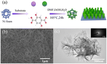 |
| | Fig. 6 Synthesis and characterization of NiFe-MOF-74. (a) Schematic illustration of the procedure for the fabrication of NiFe-MOF-74. (b) SEM image of NiFe-MOF-74. (c) TEM image and insert is SAED image for NiFe-MOF-74. Reproduced from ref. 89 with permission from Elsevier, Copyright 2021. | |
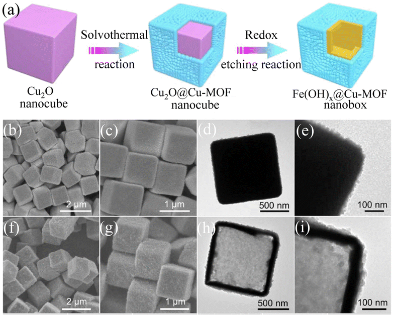
In recent years, it has been generally accepted that the hollow nanostructures of transition metal oxides and hydroxides can accommodate abundant active sites due to their high specific surface area and robust structural properties. Based on the above-mentioned concepts, the rational design of a hollow nanostructure consisting of an ultrathin MOF outer skin and a robust transition metal hydroxide will significantly improve the electrical conductivity, electrocatalytic activity, and structural stability of MOFs. Electrocatalysts composed of nanoscale conductive Cu-MOF layers fully supported on synergistic iron hydroxide [Fe(OH)x] nanoboxes exhibited a promising catalytic performance.90 The FESEM and TEM images in Fig. 7(b) and (d), respectively, show that the MOF layer completely covered the Cu2O surface in the Cu2O@Cu-MOF nano cubes after the solvothermal reaction. As shown in Fig. 7(e), Cu2O@Cu-MOF was transformed into Fe(OH)x@Cu-MOF through the redox etching process. The TEM image in Fig. 7(h) shows that the ultrathin Cu-MOF layer was fully supported on the surface of each Fe(OH)x shell. The Fe(OH)x@Cu-MOF nanobox exhibited excellent catalytic activity and stability for the HER due to its solid hollow nanostructure, extremely exposed active centers, and accelerated charge transfer rate. After the electrochemical tests, only an overpotential of 112 mV was required to reach a current density of 10 mA cm−2, and the Tafel slope reached 76 mV dec−1. Through X-ray absorption spectroscopy and density functional theory calculations, it was proven that the highly exposed Cu1–O2 centers with coordinative unsaturation could effectively accelerate the formation of the key Hads intermediates and accelerate the HER reaction kinetics.
 |
| | Fig. 7 Synthesis and characterization of Fe(OH)x@Cu-MOF NBs. (a) Schematic illustration of the synthetic process for Fe(OH)x@Cu-MOF NBs. (b and c) FESEM images of Cu2O@Cu-MOF NBs. (d and e) TEM images of Cu2O@Cu-MOF NBs. (f and g) FESEM images of Fe(OH)x@Cu-MOF NBs. (h and i) TEM images of Fe(OH)x@Cu-MOF NBs. Reproduced from ref. 90 with permission from Amer Assoc Advancement Science, Copyright 2021. | |
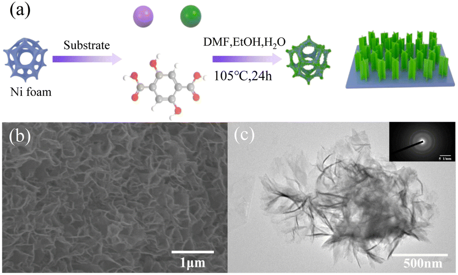
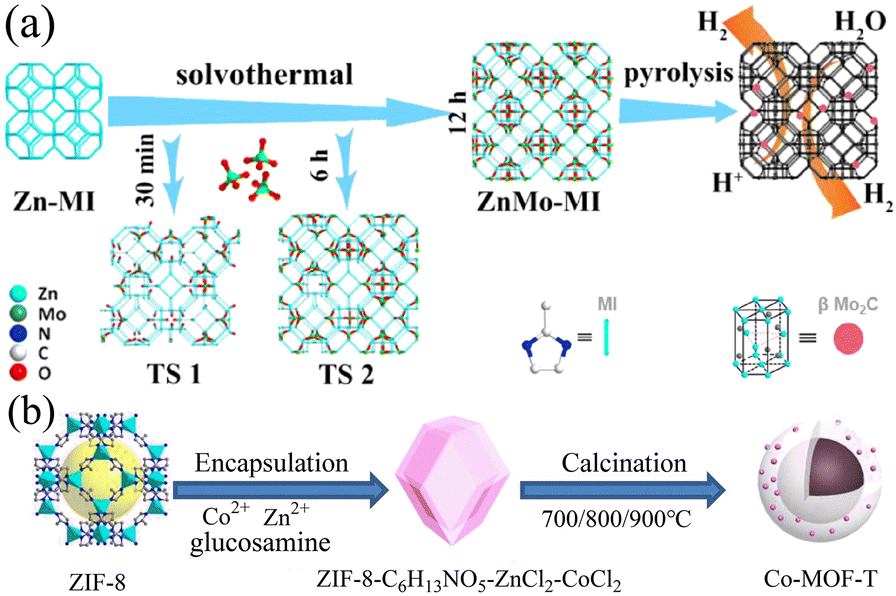
Carbon materials doped with heteroatoms or metal atoms, including carbon nanotubes, graphite, graphene, and three-dimensional porous carbon, have been extensively studied. Different metal ions such as Fe3+, Ni2+, Mn2+, and Cr3+ will act on the electrons in the catalyst to change its charge distribution, resulting in changes in the electrocatalytic performance of the catalyst.91 Alternatively, metal ions may also have a synergistic effect with the electrocatalytic reaction and promote the charge transfer and electron transport rates, thereby improving the electrocatalytic performance.92 In addition, the metal ions doped in the catalyst may serve as additional active sites to promote the electrocatalytic reaction. Studies have proven that the doping of metal ions can play a role in the formation of the structure of the catalytic material and the adjustment of the shape and area of the catalyst.93 Heteroatoms mainly refer to common non-metallic elements such as B, F, N, P, and S. Because of the low cost of non-metallic elements and their ability to promote the electrocatalytic performance, they are expected to replace noble metal catalysts. In the case of carbon materials with superior electrical conductivity, heteroatom doping can change the electronic structure, vibration mode, chemical activity, and mechanical properties of the carbon substrate, thereby changing its catalytic performance. Given that the atomic radius and electronegativity of heteroatoms are somewhat different from that of carbon atoms, the replacement of carbon atoms with heteroatoms may change the charge distribution, and thereby alter the electrochemical performance.94 In addition, studies have shown that the doping of heteroatoms will endow the catalyst material with more active sites and improve its catalytic effect.95 Using the synthesized Zn-MI as a template, ZnMo-MI-1000 obtained through solvothermal reaction and heat treatment showed an excellent HER performance.96 It exhibited good resistance in both acidic and alkaline solutions. At a current density of 10 mA cm−2, the overpotentials in 0.5 M H2SO4 and 1.0 M KOH were only 83.0 mV and 100.1 mV, and the Tafel slopes were 53.1 mV dec−1 and 88.2 mV dec−1, respectively. This was mainly due to the synergy generated among the Mo2C nanoparticles, Mo nanoparticles, and N-doped graphitic carbon matrix present in ZnMo-MI-1000. The porous nature of ZnMo-MI-1000 facilitated continuous mass transfer with minimal diffusion resistance, resulting in efficient electrocatalytic kinetics in both acidic and alkaline media. Co-MOF-T based on Zn and Co doping synthesized via the pyrolysis of ZIF-8 exhibited excellent catalytic performances in the ORR, OER, and HER.97 Its synthesis process is shown in Fig. 8. Based on its trifunctional activity, Co-MOF-800 had a lower overpotential of 520 mV and Tafel slope of 75 mV dec−1 in the OER at a current density of 10 mA cm−2 and an overpotential of 290 mV and Tafel slope of 112 mV dec−1 in the HER. This was mainly due to the existence of metallic cobalt on the surface of Co-MOF-800, in which the embedded nitrogen-doped carbon provided highly active centers for catalytic reactions. In addition, pyridinic nitrogen and Co–Nx could provide certain active sites for electrocatalytic reactions.
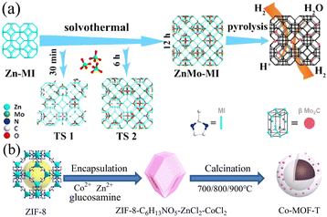 |
| | Fig. 8 Synthesis of ZnMo-MI and Co-MOF-T. (a) Schematic strategy to synthesize ZnMo-MI. Reproduced from ref. 96 with permission from Elsevier, Copyright 2021. (b) Schematic diagram of the synthesis of porous Co-MOF-T. Reproduced from ref. 97 with permission from Elsevier, Copyright 2021. | |
Combining MOFs with materials with excellent electrical conductivity is a common and effective strategy to improve their electrical conductivity. For example, in a previous study by Wu et al., two isomeric Co-MOFs synthesized with different surfactants were named CTGU-5 and CTGU-6, respectively.98 Through experimental research and analysis, it was shown that CTGU-5 exhibited higher HER electrocatalytic activity due to its more exposed cobalt active sites and coordination water. The composite material AB&CTGU-5 (1:4) formed by CTGU-5 and acetylene black exhibited the best electrocatalytic performance among the reported MOF materials. Its onset potential was only 18 mV, its Tafel slope was only 45 mV dec−1, and it had good stability. Subsequently, this team synthesized a composite material (AB&Cu-MOF) using two different methods.99 Firstly, the hydrothermal method was employed to react acetylene black and the typical Cu-BTC. For comparison, the second method was mechanical grinding. The experimental results showed that the specific surface area of the composite material prepared via the hydrothermal method was significantly lower than that by mechanical grinding, whereas it was found that AB and Cu-BTC were more uniformly combined via the hydrothermal method. Therefore, the electrical conductivity of the composites prepared via the hydrothermal method was significantly improved. Electrochemical tests showed that AB&Cu-BTC prepared via the hydrothermal method exhibited good electrocatalytic performance in 0.5 M H2SO4 solution. This was mainly due to the combined effect of its abundant exposed active centers, good electrical conductivity, and large co-contact specific surface area.
In addition, supporting catalysts on electron collectors or electrode substrates, which typically provide excellent electrical conductivity and charge transfer capabilities, helps to further enhance their catalytic capabilities. Substrates such as glassy carbon, carbon paper, carbon fabric, nickel foam, and copper foam can be used as working electrodes for supporting catalysts, where substrates with larger surface areas can have a greater loading capacity. MOFs are generally loaded onto substrates via drop casting or in situ growth. The in situ growth of nanostructured electrocatalysts on 3D porous nickel foam (NF) has been intensively studied in recent years. The advantages of NF in providing conductive pathways,100,101 improving the catalyst adaptability,102 maintaining the mechanical integrity of the catalyst,103 and positive synergistic effects between the electrocatalyst and NF substrate104 enable NF-based composites to be directly used as electrodes for water-splitting applications. Mixed Fe-MOF and Ni-MOF in the form of dispersed mesoporous interwoven nanosheets were in situ grown on nickel foam via a one-step hydrothermal method to obtain MFN-MOF/NF composites.105 After experimental investigation, they exhibited ultrahigh activity for the OER and HER at a high current density in 1.0 M KOH, with ultra-low overpotentials of 235 mV and 79 mV at 50 mA cm−2 and 10 mA cm−2, respectively. Simultaneously, their excellent long-term durability exhibited at a high current density not only indicates the excellent electrical conductivity brought by the conductive substrate NF, but the MFN-MOF (2:1)/NF electrodes also exhibited strong intermolecular synergy compared with the NF electrodes based on single-metal MOFs.
4.2 MOF derivatives as catalysts for electrolysis of water
Due to the poor conductivity and stability of MOF materials as electrocatalysts in extreme acid-base electrolytes, their development and application in the field of electrocatalysis are severely limited. Critically, in the parent metal–organic frameworks of MOF materials, the unsaturated active sites (i.e., metal center ions) need to be coordinated by adsorbed oxygen species, resulting in a decrease in their catalytic activity for the electrolysis of water. The derivatives of MOFs can inherit the porous structure and large specific surface area of the original MOFs, while exhibiting an excellent electrocatalytic performance and chemical stability. Based on this, a large number of experimental studies has been carried out on MOF derivatives.
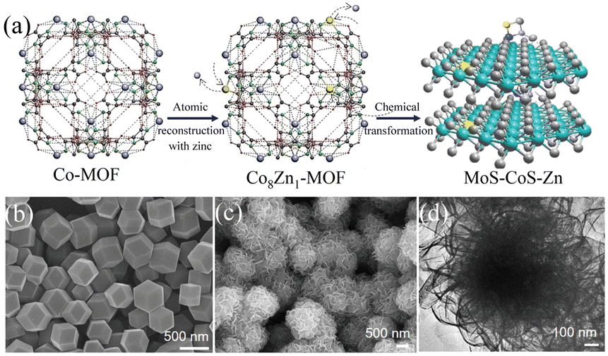
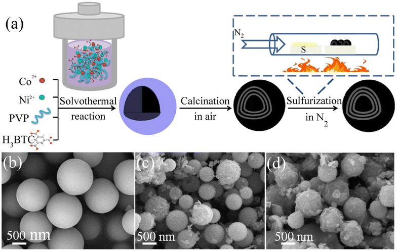
4.2.1 MOFs-derived transition metal sulfides. Transition metal sulfides (TMSs), as compounds with unique physical and chemical properties, have been extensively studied experimentally in various fields. Compared with noble metal catalysts, the advantage of transition metal sulfides as electrocatalysts is their low cost, enabling their large-scale application. Researchers have found that dichalcogenides (MX2) have efficient hydrogen evolution properties,106 where M is a transition metal (Mo, Co, Ni, Fe, W, etc.) and X is a chalcogen element. Due to the weak van der Waals force connection between the layers of two-dimensional layered disulfide compounds (MX2), methods can be used to detach the multi-layer two-dimensional materials, increase the specific surface area of the materials, and expose more potential active surfaces to enhance their catalytic activity. Among them, molybdenum disulfide (MoS2) has a typical graphene-like two-dimensional layered structure107 and has become one of the most competitive and efficient catalysts to replace the Pt noble metal due to its excellent electrocatalytic activity and low cost.108,109 Relevant studies have proven that most of the active sites of MoS2 are distributed on its edge.110 Therefore, its electrocatalytic performance can be improved by increasing the number of edges, where the use of MOFs as precursors to derive MoS2 is conducive for the construction of porous structures and the introduction of defects, thereby increasing the number of edges in MoS2. C–MoS2 composites with different carbon contents synthesized from carbon polyhedra generated by the carbonization of zeolite imidazole framework (ZIF-8) and MoS2 precursors had strong catalytic activity for the HER.111 The tuned C–MoS2 samples had a core–shell structure, in which the carbon substrate was decorated by vertically aligned MoS2 nanosheets. This core–shell structure greatly enhanced the HER activity, exposing a large number of edge active sites in MoS2, while the carbon substrate at the bottom improved the conductivity of the electrode. Its HER activity in 0.5 M H2SO4 electrolyte was significantly higher than that of MoS2 and C, and it was found that different carbon contents had a certain influence on the structure and catalytic effect of the catalyst. Therefore, the catalyst with the best catalytic activity had an overpotential of 200 mV and Tafel slope of 53 mV dec−1 at 10 mA cm−2 and maintained good stability in 0.5 M H2SO4. Simultaneously, in the process of preparing MoS2 from MOFs, foreign atoms could be introduced into the inert surface of MoS2 to construct in-plane defects, thereby changing the electronic structure of its adjacent atoms and stimulating catalytic activity in its inert surface. Structure-guided in situ reconstruction of MOFs from zinc–nitrogen-coordinated silicon-molybdenum disulfides (MoS–CoS–Zn) was shown to be a feasible strategy for the synthesis of hydrogen evolution electrocatalysts,112 which achieved constituent-specific heteroatom coordination and surface ligand functionalization. As shown in Fig. 9(a), the synthesis process involved using zinc atoms in solution to replace some of the Co atoms in Co-MOF to synthesize a cobalt zinc bimetallic organic framework, Co8Zn1-MOF, connected by a methylimidazole ligand. Subsequently, it was converted into MoS–CoS–Zn through two-step solvothermal conversion. Fig. 9(b) and (c) show that the Co8Zn1-MOF was a solid rhombic dodecahedron nanostructure, which transformed into a 3D nanosphere flower-like structure composed of a large number of 2D nanosheets after vulcanization. Comprehensive experimental spectroscopic studies and first-principles calculations demonstrated that the rationally designed electron-rich centers ensured efficient charge injection into the inert MoS2 basal plane and increased the electronic structure of the inactive sites. Zn–nitrogen coordinated cobalt disulfide-molybdenum exhibited excellent catalytic activity and stability for the hydrogen evolution reaction with a low overpotential of 72.6 mV and small Tafel slope of 37.6 mV dec−1 at 10 mA cm−2.
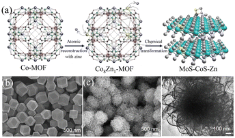 |
| | Fig. 9 Synthesis and characterization of MoS–CoS–Zn. (a) Schematic diagram of the method for the synthesis of MoS–CoS–Zn. (b) SEM image of the bimetallic organic framework (Co8Zn1-MOF). (c) SEM and (d) TEM images of MoS–CoS–Zn. Reproduced from ref. 112 with permission from John Wiley and Sons, Copyright 2019. | |
The combination of MoS2 with binary transition metal sulfides can change the valence electron orbitals of 3d metals and the electron donating and accepting characteristics, thereby enhancing the charge transfer and reducing the HER reaction barrier. Among them, NiCo2S4 has been confirmed to have excellent electrocatalytic performance and stability, and redox reactions can easily occur due to the combined effect of Ni and Co ions. Furthermore, the rich structure of NiCo2S4 opens the possibility to build hierarchical configurations, which in turn significantly enhances the HER performance. As shown in Fig. 10, Ni–Co-BTC homogeneous solid spheres prepared by the solvothermal method were subjected to a calcination and in situ gas phase vulcanization process to obtain Ni–Co–S microspheres.113 Ni–Co-BTC was observed to possess a spherical nanostructure with a smooth surface, as shown in Fig. 10(a), and Ni–Co–O formed by calcination to lose moisture and gas had a rough surface, as shown in Fig. 10(b). As shown in Fig. 10(c), Ni–Co–S and Ni–Co–O obtained after vulcanization also had a similar multi-shell hollow structure, indicating that the structure and size had not been destroyed during the vulcanization process. In the experiment, different nickel cobalt bimetallic sulfides were controlled by controlling the sulfurization temperature and sulfur source dosage. Among them, Ni–Co S-340 (60) exhibited the best HER performance, with an overvoltage of 129 mV and the minimum Tafel slope (96.1 mV dec−1) at a current density of 10 mA cm−2. This was because on the one hand, the porous characteristics and unique multi-shell hollow structure of the precursor Ni–Co-BTC were retained, while on the other hand, the strong interface effect generated by the introduction of high electrocatalytic activity NiCo2S4 in NiS2 improved its HER performance. Self-supporting MoS2/NiCo2S4 with a mace-like layered structure synthesized on carbon fiber paper (CFP) also had a good electrocatalytic performance for the HER.114 3DCFP served as the structural framework of bimetallic NiCo2S4; meanwhile, the NiCo2S4 nanowire array provided a good platform for the growth of MoS2. In this layered structure, the restacking and excessive aggregation of the 2D MoS2 nanosheets was avoided. The MoS2/NiCo2S4/CFP layered configuration provided a large number of exposed active sites, faster electron transport pathways, and electrical contacts with stronger active sites for the HER reaction. The synergy between the hierarchical structural features and abundant nanointerfaces contributed to the excellent HER performance with a low overpotential of 139 mV, Tafel slope of only 37 mV dec−1, and good stability at a current density of 10 mA cm−2.
 |
| | Fig. 10 Synthesis and characterization of Ni–Co–S. (a) Procedure for the synthesis of the Ni–Co–S. (b–d) SEM images of Ni–Co-BTC, Ni–Co–O and Ni–Co–S-340(60), respectively. Reproduced from ref. 113 with permission from Elsevier, Copyright 2019. | |
In general, transition metal sulfides will generate oxides or hydroxides on their surfaces when they undergo the OER in alkaline media.115 Compared with directly generated oxides/hydroxides, due to the controlled calcination and sulfidation process, transition metal sulfides can be closely combined with MOF-derived carbon substrates, improving the inherent activity and conductivity of the converted oxides/hydroxides. Therefore, transition metal sulfides are often used as a support to improve the conductivity of catalysts. In addition, the externally transformed oxides/hydroxides form a core–shell structure with transition metal sulfides, resulting in a synergistic effect between the components. A recently reported MOF derivative/2D MXene hybrid was in situ nucleated by ZIF-67 on exfoliated Ti3C2Tx MXene sheets and transformed into hierarchically porous NiCoS mixed metal sulfides.116 The analysis of the catalytic process showed that during the OER process, the catalyst undergoes chemical structural transformation, the valence state of the metal ions increases, and nickel cobalt oxyhydroxide/NiCoS is generated in situ on the Ti3C2Tx MXene sheet. The nickel-cobalt hydroxide oxide on the surface, as the intrinsic active substance of OER, greatly improved the catalytic activity of the hybrid, and more importantly, due to the specific structure and strong interaction between NiCoS and the Ti3C2Tx sheets, it improved the electron transfer rate and active surface area of the catalyst. In addition, the Ti3C2Tx sheet as a substrate also provided certain active sites for the catalyst.
The highly electronegative S atoms in transition metal sulfides can extract electrons from transition metal atoms, which makes transition metal sulfides have better electrocatalytic activity for the OER. Bimetallic sulfides were prepared as OER catalysts via a one-step carbonization/sulfurization method, which greatly simplified the synthesis process.117 Specifically, a nitrogen-doped nickel-iron sulfide carbon hybrid structure, N–NiFe–S/C@CC, was obtained by controlling the nickel–iron ratio for carbonization and sulfidation using carbon cloth as the substrate. The OER test was carried out in 1.0 M KOH aqueous solution and the best sample N–NiFe–S/C-8/2@CC exhibited a low overpotential of 232 mV and Tafel slope of 58 mV dec−1 at a current density of 10 mA cm−2, and also good stability. The main reason for this was that the electronic interaction among the S, Fe, and Ni atoms in the catalyst improved its OER activity, and secondly, the doping of nitrogen elements and the conductivity of the MOF-derived carbon improved the conductivity of the catalyst. In addition, direct growth on carbon cloth also achieved stronger mechanical bonding and promoted its stability.
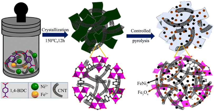
4.2.2 MOF-derived transition metal oxides. It is well known that the OER electrocatalytic activity of transition metal oxides (TMOs) without noble metals is inferior to that of noble metal catalysts with excellent electrocatalytic activity such as RuO2 (ref. 118) and IrO2,119 but transition metal oxides are considered promising electrocatalysts due to their low cost and strong redox ability.120 In recent years, there have been many studies on the use of transition metal oxides as oxygen evolution catalysts, and transition metal oxides derived from MOFs are usually obtained via heat treatment in the air.121 Among them, iron group metal (Fe, Co, and Ni) oxides have been studied as efficient OER catalysts in alkaline media.122 Heterogeneous structure oxides composed of two or more transition metals exhibit better electrocatalytic performances compared with single metal oxides. As shown in Fig. 11, FeNi3–Fe3O4 heterostructure nanoparticles uniformly anchored on MOF nanosheets and carbon nanotube (CNT) substrates were synthesized via hydrothermal and partial pyrolysis strategies.123 The electrocatalytic performance of FeNi3–Fe3O4NPs/MOF-CNT in the OER exceeded that of FeNi3–Fe3O4NPs/MOF without the CNT matrix. When the glassy carbon electrode test reached a current density of 10 mA cm−2, the overpotential was 234 mV, and the corresponding Tafel slope reached 37 mV dec−1, and it did not show obvious attenuation after 20 h of durability testing in 1.0 M KOH solution. Firstly, the adopted controlled pyrolysis strategy maintained the surface area and well-organized pore structure of the MOF, which promoted the entry of chemical substances into the active centers. Secondly, through the rational interface design of MOFs with FeNi3, Fe3O4, and CNT, FeNi3–Fe3O4 particles with excellent electronic properties were obtained on the electrode surface, which reduced the aggregation of active sites and provided a surface structure, endowing the catalyst with a fast charge transfer performance. In addition, the CNT loaded with Fe3O4 could provide a certain electron density for the corresponding active sites of metal FeNi3, endowing the catalyst with good stability.
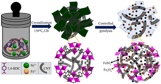 |
| | Fig. 11 Schematic diagram of the synthesis of FeNi3–Fe3O4NPs/MOF-CNT. Reproduced from ref. 123 with permission from the American Chemical Society, Copyright 2020. | |
Alternatively, transition metal Co-based oxides such as Co3O4 (ref. 124) and CoO125 have been extensively studied due to their high OER catalytic activity, low cost, and durability. In addition, studies have shown that metallic Co has a low energy barrier for hydrogen adsorption,34 which has potential application in the HER. Rationally designing composites of metal Co and transition metal Co-based oxides with bifunctional electrocatalytic properties has become a feasible research idea. Based on this, the Fe–Co–O/Co@NC-mNS/NF heterostructure electrocatalyst was obtained using a Co-MOF synthesized on nickel foam and K3 [Fe(CN)6] solution after the initial treatment in an argon atmosphere through a two-step heating method and in situ oxidation.126 In the electrochemical tests, the OER and HER exhibited lower overpotentials of 257 mV and 112 mV at a current density of 10 mA cm−2, respectively, while for overall water splitting, the electrolytic cell only needed a low cell potential of 1.58 V to reach 10 mA cm−2. Doping Fe into the host Co-based material during the synthesis of the catalyst was beneficial to generate defective active sites and improve the electrical conductivity of the host material.127 Furthermore, in situ oxidation changed the micro-columnar structure of Fe–Co–O/Co@NC/NF into a thin nanosheet structure, which introduced structural defects and its larger electrochemical activity-specific surface area exposed more active sites. Simultaneously, the oxygen vacancies produced during the in situ oxidation process accelerated the charge transfer, and thus exhibited excellent electrocatalytic activity for the OER.128
Among the transition metal oxides, ABO3-type perovskites have attracted extensive attention due to their abundant content, low element cost, high electrocatalytic activity, and easy mass production.129,130 However, the small specific surface area and poor electrical conductivity of metal oxides have become important factors restricting their catalytic performance.131 The transition metal oxides derived from MOFs have increased conductivity and specific surface due to the addition of an external carbon source, thereby exhibiting the catalytic properties of oxides. In addition, the oxygen vacancies in the catalyst, as an important determinant in the catalytic process, profoundly affect the OER catalytic activity and stability of the catalyst. The carbon-cobalt/perovskite hybrid product GBCF40@Co–C was used as an efficient and stable oxygen evolution catalyst.132 The Fe-doped perovskite oxide GdBaCo2−xFexO5+δ was surface modified, and PVP was used as a surfactant to form the core–shell structure GBCF40@ZIF-67 with ZIF-67, and the GBCF40@Co–C catalyst was obtained by controlling the pyrolysis temperature and the amount of ZIF-67. The experimental results showed that the overpotential of the modified GBCF40@Co–C slightly increased, which was 309 mV at a current density of 10 mA cm−2, and its Tafel slope was 86.88 mV dec−1. Furthermore, its electrocatalytic stability greatly improved, which was stronger than the noble metal catalyst RuO2 in the comprehensive performance test for 12 h. Given that the B site coordinated with the O anion in perovskite usually represents the active site of the oxygen intermediate, B site doping can change the electronic structure of the metal active site. The B-site doping of the Fe element affected the valence state and electronic structure of Co and increased the oxygen vacancies, which improved the catalytic performance of the catalyst. Simultaneously, the strong coupling between the modified GBCF40@Co–C carbon and carbon was the key reason for the good stability, and the combination with ZIF-67 also improved the conductivity and electrocatalytic active area of the material itself.
In addition, the transition metal oxides generated on the electrode surface in the hydrogen evolution reaction can enhance the electrocatalytic activity in an alkaline solution,133 greatly improving the slow hydrogen evolution reaction kinetics in alkaline media.134 A composite structure Co@Co3O4-NC hydrogen evolution catalyst was formed via the carbonization and partial oxidation of ZIF-67 in an N2 atmosphere.135 The structure anchored the partially oxidized Co nanoparticles in the N-doped carbon positive dodecahedron framework, where the Co3O4 shell acted as an effective charge separation functional layer, while the metal Co core immediately transferred the separated charges to the N–C framework, improving the electrocatalytic performance by accelerating the speed of charge separation and transfer. When the current density of 1.0 M KOH solution reached 10 mA cm−2, the overpotential for the HER was 221 mV, making Co@Co3O4-NC a good HER electrocatalyst for application in alkaline media.
4.2.3 MOF-derived transition metal carbides. Transition metal carbides (TMCs) are often used as a substitute for noble metal catalysts due to their low production cost, good electrical conductivity, and stability. For example, metal carbides such as WC136 and MoxC137 have been proven to be good HER electrocatalysts. At higher temperatures, transition metal carbides are formed by introducing carbon atoms into the metal lattice, which have catalytic properties and electronic structures similar to noble metal Pt catalysts.138,139 Among them, MoxC is a material with a high melting point, which often requires higher temperature annealing during the synthesis process.140 However, high temperatures will lead to aggregation or coarsening of the highly crystalline MoxC,141 resulting in the loss of a large number of its active sites and decrease in its HER catalytic activity. Therefore, high-temperature annealing using the corresponding MOF materials is an effective method to prepare MoxC. Mo precursors are dispersed or confined in the surface or pores of MOFs and in situ carbonized into MoxC@C nanoparticles during pyrolysis, and the presence of a carbon matrix prevents the coalescence and aggregation of MoxC. In addition, the carbon matrix provides porous channels for mass transfer and high conductivity for electron transfer. A method for preparing Co-NC@Mo2C complexes based on MOFs was previously reported. ZIF-67 was prepared and ground with ammonium molybdate tetrahydrate, carbonized under a pure argon flow, and annealed at 700 °C for 3 h to obtain Co-NC@Mo2C.142 As shown in Fig. 12(b), the synthesized ZIF-67 exhibited a rhombic dodecahedral structure with a smooth surface. After grinding, its surface was covered by ammonium molybdate and became rough, the Co ions in ZIF-67 were reduced to CoNPs after carbonization under a high-temperature argon atmosphere, carbonitrides were formed around the CoNPs, and ammonium molybdate was converted to Mo2C. This complex combined the advantages of Mo2C with Co-NC, and an overpotential of 143 mV and 99 mV was required to achieve a current density of 10 mA cm−2 during the HER in acidic and alkaline media, respectively. The coating structure formed by Mo2C in the composite protected the electrocatalytic reaction sites of Co particles, provided more metal-active sites, and enhanced the electrocatalytic performance of the catalyst.
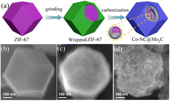 |
| | Fig. 12 Synthesis and characterization of Co-NC@Mo2C. (a) Diagram of the process for the formation of Co-NC@Mo2C. (b–d) FESEM images of the as-prepared ZIF-67, ammonium molybdate tetrahydrate wrapped ZIF-67 and Co-NC@Mo2C, respectively. Reproduced from ref. 142 with permission from Elsevier, Copyright 2019. | |
However, this method will inevitably cause excessive carbon deposition, which will block the surface active sites of MoxC, thereby reducing the mass activity of the electrode materials. Simultaneously, MoxC is limited by the high density of vacancies in its structure, and strong H binding will inhibit the desorption of H in the adsorbed state to produce H,143 and the introduction of electron-rich heteroatoms such as N, S, and P will reduce the hollow d-band density of MoxC and weaken the strength of Mo–H. Based on this, the topological transformation method of nitrogen-doped porous Mo2C mesogens (N–Mo2C/CFP) synthesized on carbon fiber paper using ZIF-67 as a nitrogen and carbon source in the gas–solid reaction route was proposed for the first time.144 Firstly, MoO3·H2O was conformally coated on the surface of CFP to form a core–shell structure, and MoO3·H2O nanoparticles were converted into MoO3 nanosheets after calcination and dehydration in the air. With an increase in the electrodeposition time, MoO3 nanoplates gradually accumulated and serious overlapping of the nanoplates appeared in N–Mo2C/CFP-60. Also, the nanoplates with a rough surface were well preserved after ZIF-67-assisted non-contact carbonization by gas–solid reaction in N–Mo2C/CFP-30 and N–Mo2C/CFP-45. Among them, N–Mo2C/CFP-45 exhibited the best electrocatalytic HER performance. An overpotential of only 45 mV was needed to achieve the current density of 10 mA cm−2 in 0.5 M H2SO4 solution, and the Tafel slope was 44 mV dec−1, while overpotentials of 80 mV and 36 mV were required in neutral and alkaline media, and the corresponding Tafel slopes were 65 and 32 mV dec−1, respectively. In addition, the excellent thermal stability of N–Mo2C/CFP-45 endowed the catalyst with excellent stability and durability. Compared with the polycrystalline Mo2C that was reported thus far, the as-prepared porous Mo2C mesogenic with higher grain orientation had similar properties to single-crystal Mo2C, significantly enhancing the charge transfer rate in its crystal framework. Simultaneously, its abundant porous characteristics and carbon-free residues increased the exposed active sites, and nitrogen doping also improved the catalytic activity of Mo2C for the HER.
Based on the encapsulation and in situ carbonization reaction of a copper-based metal–organic framework (NENU-5), the porous nano-octahedral material MoWN/MoWC@NACATs obtained via the strategy of MOF encapsulation-assisted synthesis was used as an efficient hydrogen evolution catalyst for the electrolysis of water.145 By introducing hydrated phosphomolybdic acid and hydrated phosphotungstic acid as precursors in copper-based MOFs, combined with the vapor deposition method, the nano-octahedral particles fixed the volatile nitrogen generated by the pyrolysis of dicyandiamide, and thus tungsten–molybdenum-based oxides and solid carbon were nitrided to form MoWN/MoWC@NACATs. After electrochemical tests, the HER overpotential of MoWN/MoWC@NACA800 was as low as −0.17 V (vs. RHE) and its Tafel slope was about 73 mV dec−1, which was slightly higher than that of commercial Pt/C catalysts. Its excellent catalytic activity was derived from the unique porous nano-octahedral Mo2N/MoC/W2N/WC heterogeneous material, and the carbonization temperature and synergistic effect of the multi-component heterogeneous structure greatly enhanced the multifunctional performance of the material. The encapsulation and vapor deposition methods used in the preparation process effectively prevented the accumulation and loss of active materials and ensured the uniform distribution of active sites in the catalyst, significantly improving its electrocatalytic performance.
4.2.4 MOF-derived transition metal phosphides. Transition metal phosphides (TMPs) have both semiconductor and metal properties, and their special electronic structure endows them with excellent conductivity, rapid charge transfer, and improved reaction kinetics when used as electrocatalysts, and thus they have high catalytic activity in the HER. According to the study of nickel phosphide by Liu et al.,146 it was found that nickel phosphide exhibits a similar catalytic mechanism as hydrogenase and excellent catalytic performance in the HER. Various phosphides such as Ni2P,147 CoP,148 FeP,149 and MoP150 have gradually been found to have good electrical conductivity and catalytic activity, and their good HER catalytic performance has also been experimentally proven. For example, Ni-MOF was synthesized via a simple solvothermal method, and a well-organized Ni2P/Ni@C hybrid with a carbon coating was obtained through a stepwise carbonization and phosphating process.151 Compared with the RHE, the HER test in 0.5 M H2SO4 solution showed that the required overpotential at a current density of 10 mA cm−2 was only 149 mV. The optimized hierarchical micro–nano structure of the Ni2P material provided more contact area between the electrode and the electrolyte, and the carbon coating of the catalyst provided better conductivity and avoided the agglomeration and pulverization of the active material. More importantly, the synergistic effect between Ni2P and Ni led to faster charge transfer and enhanced catalytic activity in Ni2P/Ni@C. Generally, transition metal phosphides derived from MOFs are generated by the pyrolysis of MOFs and phosphorus sources under inert gas. However, when MOFs are used as precursors to be converted into transition metal phosphides through high-temperature calcination, problems such as destruction of the original MOF material structure and aggregation of the metal active centers often occur. Moreover, the unsaturated coordination centers of MOFs have a stronger adsorption effect on oxygen-containing substances than hydrogen-containing substances, resulting in an unsatisfactory HER performance. Therefore, it is a serious challenge to design hybrid catalysts integrating TMP and MOFs to make ΔGH* close to the optimal value. Co-MOF was prepared via the hydrothermal deposition of Co(OH)F on carbon fiber paper and reaction with imidazole vapor, which was subsequently partially phosphate by reaction with sodium hypophosphite to obtain CoP/Co-MOF.152 Among them, the Co-MOF converted from Co(OH)F by gas phase reaction retained the needle-like morphology, which enhanced the mass transfer process in the catalytic process. The transfer of electrons from CoP to Co-MOF through N–P and N–Co bonds increased the adsorption energy of water and hydrogen. This enabled it to achieve a current density of 10 mA cm−2 when performing the HER in 1 M phosphate buffer solution (PBS, pH = 7.0) with an overpotential of only 49 mV, and it also exhibited similar properties to Pt under acid–base conditions.In transition metal phosphide systems, the positively charged metal ions can serve as hydroxyl acceptors, while the negatively charged phosphorus active sites play an important role in promoting the desorption of O2 molecules, and thus can also be used as OER electrocatalysts. However, under the strong oxidation conditions of the OER, due to the poorer thermal stability of transition metal phosphides than oxides, similar sulfides will be converted into oxides or hydroxides during OER oxidation. Among them, the catalytic performance of transition metal phosphide-converted oxides or hydroxides is often higher than that synthesized by common methods. Therefore, taking advantage of the fact that P and S are less electronegative than oxygen in hydroxides, combining heteroatoms with different atomic radii and electronegativities (P, S, etc.) in the lattice of metal phosphides is an important way to increase the number of active sites, optimize the formation energy of intermediates and redistribute the electronic structure to improve the electrocatalytic activity of the material. A series of S-doped NiFeP catalysts with high catalytic activity was prepared by using porous conductive carbon cloth (CC) and S-containing MOFs (CPM-443-SH) as substrates and precursors, respectively, which were in situ grown on the carbon cloth and subjected to mild phosphating treatment.153 Density functional theory (DFT) calculations showed that the doping of S elements led to the formation of metal–sulfur bonds. The formed metal–sulfur bond played an important role in regulating the electronic structure of the catalyst, effectively lowering the energy barrier during the adsorption and reaction pathways for the OER. Moreover, S doping played a crucial role in promoting the formation of OOH* and further releasing O2 during the OER process. The as-prepared S–NiFeP-10 sample exhibited an excellent OER performance and outstanding durability in 1.0 M KOH electrolyte. It yielded the highest OER activity at a current density of 10 mA cm−2 with an overpotential of 201 mV without iR compensation.
Transition metal phosphides are often used as bifunctional catalysts for water electrolysis due to their good electrocatalytic performance in both the HER and OER. Also to improve the electrocatalytic performance of transition metal phosphides, doping with different transition elements,154 heteroatoms,155 and organic ligands156 or using multiple phases as the active center becomes an effective means of electrocatalytic activity enhancement through the synergistic interactions between elements. The Ni2P–CoP bifunctional catalyst was synthesized from NiCo-MOF as a precursor via a low-temperature phosphating strategy.157 The OER and HER overpotentials of the Ni2P–CoP catalyst at a current density of 10 mA cm−2 were 320 mV and 105 mV, respectively. The strong synergistic effect existing in Ni2P–CoP was demonstrated compared with the significant advantages of the Ni2P or CoP catalyst alone. Compared with the Ni2P + CoP catalyst obtained via mechanical mixing, the stronger electrocatalytic performance of Ni2P–CoP demonstrated its strong interfacial effect. Alternatively, heterostructure catalysts based on transition metal phosphides are heterostructures composed of two solid materials coupled through interfacial interactions. These catalysts not only have the inherent characteristics of the two materials, but also new performance advantages due to the interfacial effects, and thus heterostructures produced by designing different conductive substrates can have various advantages such as improved conductivity. As shown in Fig. 13, the Ti2NTx@MOF-CoP composite material self-assembled by phosphating precursor ZIF-67 and Ti2NTx MXene nanosheets had a strong hydrogen evolution performance.158 Especially under alkaline conditions, when pH = 14, the overpotential of only 112 mV was needed to reach the current density of 10 mA cm−2, and it showed strong stability after 20 h of cycle test. This was because MOF-CoP had a large specific surface area and strong catalytic activity. The introduction of Ti2NTx not only provided more active sites but also made the heterostructure of the catalyst more stable.
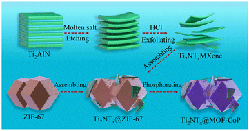 |
| | Fig. 13 Schematic of the synthesis of Ti2NTx@MOF-CoP. Reproduced from ref. 158 with permission from Elsevier, Copyright 2021. | |
5 Summary and outlook
Herein, we reviewed the recent research progress on MOFs as catalysts for the electrolysis of water, including MOF materials, transition metal sulfides, transition metal oxides, transition metal carbides, and transition metal phosphides derived from MOFs. Simultaneously, the mechanism of the hydrogen evolution reaction and oxygen evolution reaction, the relevant evaluation parameters of electrocatalysts, the research status of MOF-based materials, and the main synthesis methods were explained, summarized and prospected.
In the case of pristine MOFs, their electrocatalytic properties can be enhanced by controlling their morphology to expose more active sites, designing their organic ligands, building two-dimensional nanosheet structures, combining them with conductive materials to enhance their conductivity, and doping with the corresponding heteroatoms. The derivatives of MOFs not only inherit the characteristics of the MOF precursors such as porous structure, high-density active sites, and adjustable pore size, but also have stronger chemical stability. To improve the electrocatalytic performance of MOF materials, their structural design and electronic regulation through different methods are indispensable. Herein, the following methods were summarized: (1) shape control, MOF electrocatalysts with special shapes such as nanosheets and nanowires were prepared by direct synthesis using sacrificial templates and orderly deposition. Different morphological structures will change the catalyst reaction interface and provide a large number of coordinatively unsaturated active centers and faster charge transfer paths. (2) Constructing defects, generating defects (oxygen vacancies and metal ion vacancies) in metal–organic frameworks through ion-exchange synthesis, exposing a large number of active sites and accelerating the charge transfer rate. (3) Changing the electronic structure by doping atoms. The electronic structure of MOF materials (such as density of states, d-band centers of transition metals, and charge polarization) can be adjusted by introducing vacancies, heteroatoms, alloys, etc. (4) Through interfacial interaction, synergistic functional systems, and protection of corrosion-resistant components, MOFs composites have good charge transfer ability, catalytic activity, and corrosion resistance stability. (5) Obtaining the main surface-active components in catalysis through surface modification such as partial surface oxidation, high-energy crystal plane, and surface reorganization.
Although there are many studies on MOFs in the electrolysis of water, there are still many challenges in the application of MOFs for industrial hydrogen production. Given the main problems existing in MOFs at present, the future development direction prospects are as follows: (1) development of more types of MOFs for water electrolysis to produce hydrogen. Currently, numerous MOF materials have been reported, but only a few have been applied in electrocatalytic water splitting. Given that the morphology of the MOF precursors usually determines the electrocatalytic performance of MOF catalysts, researching more types of MOF precursors is conducive to discovering more types of active sites and increasing the number of potential active sites. Among them, catalysts based on atomic-level MOFs have become research hotspots, but it is still challenging to prepare single-atom MOFs with more active sites. (2) The preparation method and process mechanism of MOF-derived materials still need to be further explored. Most of the MOF-derived materials used in the electrolysis of water are formed by heat treatment methods such as pyrolysis and calcination, but high temperature will lead to a reduction in the catalytic active centers of MOF materials. Therefore, preparation methods under low-temperature conditions should become the key direction of future research. Simultaneously, the specific process for the change in MOF materials during heat treatment is still unclear, and the development of derivative technologies for forming controllable morphology and structure needs to be accelerated. (3) The design and synthesis of MOFs with a smaller overpotential, stronger conductivity, and stability. Firstly, the overpotential of the currently existing MOFs is still not comparable to that of commercial noble metal catalysts, and thus further development is still needed. Secondly, the poor electrical conductivity of MOFs severely limits the catalytic performance of MOF materials. Although they can be combined with highly conductive materials to improve their charge transfer efficiency, there is still interfacial resistance between MOFs and conductive substrates. Therefore, developing charge-conducting MOFs is a new challenge. Finally, methods to maintain the stability of MOF materials during electrocatalysis in acid–base solutions need to be studied intensively.
Author contributions
Conceptualization, X. C., and Y. G.; methodology, Y. G., G. T., and W. Z.; validation, Y. L., and Z. Z.; formal analysis, X. C., and Y. G.; investigation, X. C.; resources, Y. G., W. Z., and B. C.; data curation, X. C.; writing—original draft preparation, Y. G., and X. C.; writing—review and editing, G. T., D. W.; supervision, Y. G., X. Z., and B. C.; project administration, Y. G.; funding acquisition, Y. G., W. Z., and B. C. All authors have read and agreed to the published version of the manuscript.
Conflicts of interest
There are no conflicts to declare.
Acknowledgements
China Postdoctoral Science Foundation (2020M671983); Postdoctoral Innovation Project of Shandong Province (202103077); China Scholarship Council (202008370134); Shandong Province Housing and Urban-Rural Construction Science and Technology Project (2022-K7-11, 2021-K8-10, 2020-K2-10); National Natural Science Foundation of China (51976111); Doctoral Fund of Shandong Jianzhu University (X18069Z); The Plan of Guidance and Cultivation for Young Innovative Talents of Shandong Provincial Colleges and Universities.
References
- J. A. Turner, Science, 2004, 305, 972–974 CrossRef CAS PubMed.
- S. Chu, Y. Cui and N. Liu, Nat. Mater., 2017, 16, 16–22 CrossRef.
- S. Chu and A. Majumdar, Nature, 2012, 488, 294–303 CrossRef CAS.
- S. E. Hosseini and M. A. Wahid, Renewable Sustainable Energy Rev., 2016, 57, 850–866 CrossRef CAS.
- P. Nikolaidis and A. Poullikkas, Renewable Sustainable Energy Rev., 2017, 67, 597–611 CrossRef CAS.
- R. Razzaq, C. S. Li and S. J. Zhang, Fuel, 2013, 113, 287–299 CrossRef CAS.
- H. F. Abbas and W. Daud, Int. J. Hydrogen Energy, 2010, 35, 1160–1190 CrossRef CAS.
- S. Sa, H. Silva, L. Brandao, J. M. Sousa and A. Mendes, Appl. Catal., B, 2010, 99, 43–57 CrossRef CAS.
- K. Zeng and D. K. Zhang, Prog. Energy Combust. Sci., 2010, 36, 307–326 CrossRef CAS.
- I. Dincer and C. Acar, Int. J. Hydrogen Energy, 2015, 40, 11094–11111 CrossRef CAS.
- N. T. Suen, S. F. Hung, Q. Quan, N. Zhang, Y. J. Xu and H. M. Chen, Chem. Soc. Rev., 2017, 46, 337–365 RSC.
- Y. Zheng, Y. Jiao, Y. H. Zhu, L. H. Li, Y. Han, Y. Chen, A. J. Du, M. Jaroniec and S. Z. Qiao, Nat. Commun., 2014, 5, 3783 CrossRef PubMed.
- S. Anantharaj, S. R. Ede, K. Sakthikumar, K. Karthick, S. Mishra and S. Kundu, ACS Catal., 2016, 6, 8069–8097 CrossRef CAS.
- S. Sultan, J. N. Tiwari, A. N. Singh, S. Zhumagali, M. Ha, C. W. Myung, P. Thangavel and K. S. Kim, Adv. Energy Mater., 2019, 9, 1900624 CrossRef.
- X. D. Wang, Y. F. Xu, H. S. Rao, W. J. Xu, H. Y. Chen, W. X. Zhang, D. B. Kuang and C. Y. Su, Energy Environ. Sci., 2016, 9, 1468–1475 RSC.
- J. S. Li, Y. Wang, C. H. Liu, S. L. Li, Y. G. Wang, L. Z. Dong, Z. H. Dai, Y. F. Li and Y. Q. Lan, Nat. Commun., 2016, 7, 11204 CrossRef CAS.
- J. W. Su, Y. Yang, G. L. Xia, J. T. Chen, P. Jiang and Q. W. Chen, Nat. Commun., 2017, 8, 14969 CrossRef PubMed.
- Q. He, D. Tian, H. L. Jiang, D. F. Cao, S. Q. Wei, D. B. Liu, P. Song, Y. Lin and L. Song, Adv. Mater., 2020, 32, 1906972 CrossRef CAS PubMed.
- L. Y. Zeng, K. A. Sun, X. B. Wang, Y. Q. Liu, Y. Pan, Z. Liu, D. W. Cao, Y. Song, S. H. Liu and C. G. Liu, Nano Energy, 2018, 51, 26–36 CrossRef CAS.
- R. Boppella, J. Tan, W. Yang and J. Moon, Adv. Funct. Mater., 2019, 29, 1807976 CrossRef.
- J. R. Li, R. J. Kuppler and H. C. Zhou, Chem. Soc. Rev., 2009, 38, 1477–1504 RSC.
- Z. C. Hu, B. J. Deibert and J. Li, Chem. Soc. Rev., 2014, 43, 5815–5840 RSC.
- J. W. Liu, L. F. Chen, H. Cui, J. Y. Zhang, L. Zhang and C. Y. Su, Chem. Soc. Rev., 2014, 43, 6011–6061 RSC.
- M. X. Wu and Y. W. Yang, Adv. Mater., 2017, 29, 1606134 CrossRef.
- Y. B. Huang, J. Liang, X. S. Wang and R. Cao, Chem. Soc. Rev., 2017, 46, 126–157 RSC.
- Y. Z. Chen, R. Zhang, L. Jiao and H. L. Jiang, Coord. Chem. Rev., 2018, 362, 1–23 CrossRef CAS.
- J. D. Benck, T. R. Hellstern, J. Kibsgaard, P. Chakthranont and T. F. Jaramillo, ACS Catal., 2014, 4, 3957–3971 CrossRef CAS.
- J. Durst, A. Siebel, C. Simon, F. Hasche, J. Herranz and H. A. Gasteiger, Energy Environ. Sci., 2014, 7, 2255–2260 RSC.
- J. Wang, F. Xu, H. Jin, Y. Chen and Y. Wang, Adv. Mater., 2017, 29, 1605838 CrossRef.
- L. Han, S. Dong and E. Wang, Adv. Mater., 2016, 28, 9266–9291 CrossRef CAS PubMed.
- J. J. Song, C. Wei, Z. F. Huang, C. T. Liu, L. Zeng, X. Wang and Z. C. J. Xu, Chem. Soc. Rev., 2020, 49, 2196–2214 RSC.
- J. Q. Shan, Y. Zheng, B. Y. Shi, K. Davey and S. Z. Qiao, ACS Energy Lett., 2019, 4, 2719–2730 CrossRef CAS.
- J. S. Yoo, X. Rong, Y. Liu and A. M. Kolpak, ACS Catal., 2018, 8, 4628–4636 CrossRef CAS.
- Y. Zheng, Y. Jiao, M. Jaroniec and S. Z. Qiao, Angew. Chem., Int. Ed., 2015, 54, 52–65 CrossRef CAS.
- P. Sabatier, La catalyse en chimie organique, Béranger, 1920 Search PubMed.
- E. Skulason, V. Tripkovic, M. E. Bjorketun, S. Gudmundsdottir, G. Karlberg, J. Rossmeisl, T. Bligaard, H. Jonsson and J. K. Norskov, J. Phys. Chem. C, 2010, 114, 18182–18197 CrossRef CAS.
- T. R. Cook, D. K. Dogutan, S. Y. Reece, Y. Surendranath, T. S. Teets and D. G. Nocera, Chem. Rev., 2010, 110, 6474–6502 CrossRef CAS.
- S. Wang, A. L. Lu and C. J. Zhong, Nano Convergence, 2021, 8, 4 CrossRef CAS.
- M. Zeng and Y. G. Li, J. Mater. Chem. A, 2015, 3, 14942–14962 RSC.
- S. Anantharaj, S. R. Ede, K. Karthick, S. S. Sankar, K. Sangeetha, P. E. Karthik and S. Kundu, Energy Environ. Sci., 2018, 11, 744–771 RSC.
- Z. Y. Cai, X. M. Bu, P. Wang, J. C. Ho, J. H. Yang and X. Y. Wang, J. Mater. Chem. A, 2019, 7, 5069–5089 RSC.
- M. H. Shao, Q. W. Chang, J. P. Dodelet and R. Chenitz, Chem. Rev., 2016, 116, 3594–3657 CrossRef CAS.
- S. Anantharaj and S. Kundu, ACS Energy Lett., 2019, 4, 1260–1264 CrossRef CAS.
- S. Anantharaj, P. E. Karthik and S. Noda, Angew. Chem., Int. Ed., 2021, 60, 23051–23067 CrossRef CAS PubMed.
- S. Mukhopadhyay, O. Basu and S. K. Das, ChemCatChem, 2020, 12, 5430–5438 CrossRef CAS.
- S. Anantharaj and S. Noda, ChemElectroChem, 2020, 7, 2297–2308 CrossRef CAS.
- C. Wei, S. Sun, D. Mandler, X. Wang, S. Z. Qiao and Z. J. Xu, Chem. Soc. Rev., 2019, 48, 2518–2534 RSC.
- J. Yu, Q. Li, N. Chen, C.-Y. Xu, L. Zhen, J. Wu and V. P. Dravid, ACS Appl. Mater. Interfaces, 2016, 8, 27850–27858 CrossRef CAS.
- S. Anantharaj, S. R. Ede, K. Karthick, S. Sam Sankar, K. Sangeetha, P. E. Karthik and S. Kundu, Energy Environ. Sci., 2018, 11, 744–771 RSC.
- O. M. Yaghi, G. Li and H. Li, Nature, 1995, 378, 703–706 CrossRef CAS.
- K. S. Park, Z. Ni, A. P. Côté, J. Y. Choi, R. Huang, F. J. Uribe-Romo, H. K. Chae, M. O'Keeffe and O. M. Yaghi, Proc. Natl. Acad. Sci. U. S. A., 2006, 103, 10186–10191 CrossRef CAS PubMed.
- S. L. Zhao, C. H. Tan, C. T. He, P. F. An, F. Xie, S. Jiang, Y. F. Zhu, K. H. Wu, B. W. Zhang, H. J. Li, J. Zhang, Y. Chen, S. Q. Liu, J. C. Dong and Z. Y. Tang, Nat. Energy, 2020, 5, 881–890 CrossRef CAS.
- X. Y. Xie, L. S. Peng, H. Z. Yang, G. I. N. Waterhouse, L. Shang and T. R. Zhang, Adv. Mater., 2021, 33, 2101038 CrossRef CAS.
- J. Li, H. L. Huang, W. J. Xue, K. Sun, X. H. Song, C. R. Wu, L. Nie, Y. Li, C. Y. Liu, Y. Pan, H. L. Jiang, D. H. Mei and C. L. Zhong, Nat. Catal., 2021, 4, 719–729 CrossRef CAS.
- J. B. Lin, T. T. T. Nguyen, R. Vaidhyanathan, J. Burner, J. M. Taylor, H. Durekova, F. Akhtar, R. K. Mah, O. Ghaffari-Nik, S. Marx, N. Fylstra, S. S. Iremonger, K. W. Dawson, P. Sarkar, P. Hovington, A. Rajendran, T. K. Woo and G. K. H. Shimizu, Science, 2021, 374, 1464 CrossRef CAS.
- H. Liu, Y. Lan, C. Zhao and J. Liu, Chin. J. Anal. Chem., 2023, 1–15, DOI:10.19756/j.issn.0253-3820.231006.
- Z. Niu, X. L. Cui, T. Pham, G. Verma, P. C. Lan, C. Shan, H. B. Xing, K. A. Forrest, S. Suepaul, B. Space, A. Nafady, A. M. Al-Enizi and S. Q. Ma, Angew. Chem., Int. Ed., 2021, 60, 5283–5288 CrossRef CAS PubMed.
- X. Li, G. Zhu, C. Wang, J. Zhu, H. Xu and X. He, J. China Coal Soc., 2023, 1–11, DOI:10.13225/j.cnki.jccs.2022.1795.
- K. Suresh, D. Aulakh, J. Purewal, D. J. Siegel, M. Veenstra and A. J. Matzger, J. Am. Chem. Soc., 2021, 143, 10727–10734 CrossRef CAS PubMed.
- M. Taheri, D. Ashok, T. Sen, T. G. Enge, N. K. Verma, A. Tricoli, A. Lowe, D. R. Nisbet and T. Tsuzuki, Chem. Eng. J., 2021, 413, 127511 CrossRef CAS.
- Z. J. Fan, H. X. Liu, Y. H. Xue, J. Y. Lin, Y. Fu, Z. H. Xia, D. M. Pan, J. Zhang, K. Qiao, Z. Z. Zhang and Y. H. Liao, Bioact. Mater., 2021, 6, 312–325 CrossRef CAS PubMed.
- H. Karimi-Maleh, M. L. Yola, N. Atar, Y. Orooji, F. Karimi, P. S. Kumar, J. Rouhi and M. Baghayeri, J. Colloid Interface Sci., 2021, 592, 174–185 CrossRef CAS PubMed.
- C. L. Liu, Y. Bai, W. T. Li, F. Y. Yang, G. X. Zhang and H. Pang, Angew. Chem., Int. Ed., 2022, 61, e202116282 CrossRef CAS PubMed.
- S. Lee, S. Oh and M. Oh, Angew. Chem., Int. Ed., 2020, 59, 1327–1333 CrossRef CAS.
- X. Huang, P. Sheng, Z. Tu, F. Zhang, J. Wang, H. Geng, Y. Zou, C.-a. Di, Y. Yi, Y. Sun, W. Xu and D. Zhu, Nat. Commun., 2015, 6, 7408 CrossRef.
- D. Zhao, X. H. Liu, J. H. Guo, H. J. Xu, Y. Zhao, Y. Lu and W. Y. Sun, Inorg. Chem., 2018, 57, 2695–2704 CrossRef CAS PubMed.
- Y. X. Chen, D. Ni, X. W. Yang, C. C. Liu, J. L. Yin and K. F. Cai, Electrochim. Acta, 2018, 278, 114–123 CrossRef CAS.
- T. J. Ferreira, R. Ribeiro, J. P. B. Mota, L. P. N. Rebelo, J. Esperanca and I. Esteves, ACS Appl. Nano Mater., 2019, 2, 7933–7950 CrossRef CAS.
- D. F. Lv, Y. W. Chen, Y. J. Li, R. F. Shi, H. X. Wu, X. J. Sun, J. Xiao, H. X. Xi, Q. B. Xia and Z. Li, J. Chem. Eng. Data, 2017, 62, 2030–2036 CrossRef CAS.
- X. Huang, P. Sheng, Z. Y. Tu, F. J. Zhang, J. H. Wang, H. Geng, Y. Zou, C. A. Di, Y. P. Yi, Y. M. Sun, W. Xu and D. B. Zhu, Nat. Commun., 2015, 6, 7408 CrossRef CAS PubMed.
- Z. K. Hu, B. Zhao, S. Zhang, Z. Y. Tan, X. W. Liu and J. L. Cao, Microporous Mesoporous Mater., 2019, 281, 75–83 CrossRef CAS.
- M. Y. Li and M. Dinca, J. Am. Chem. Soc., 2011, 133, 12926–12929 CrossRef CAS PubMed.
- Y. C. Ding, Y. Q. Peng, W. Y. Chen, Y. J. Niu, S. G. Wu, X. X. Zhang and L. H. Hu, Appl. Surf. Sci., 2019, 493, 368–374 CrossRef CAS.
- F. Yang, W. Y. Li and B. H. J. Tang, J. Alloys Compd., 2018, 733, 8–14 CrossRef CAS.
- A. Badoei-dalfard, N. Sohrabi, Z. Karami and G. Sargazi, Biosens. Bioelectron., 2019, 141, 111420 CrossRef CAS.
- B. Szczesniak, J. Choma and M. Jaroniec, Microporous Mesoporous Mater., 2019, 279, 387–394 CrossRef CAS.
- H. B. Aiyappa, J. Masa, C. Andronescu, M. Muhler, R. A. Fischer and W. Schuhmann, Small Methods, 2019, 3, 1800415 CrossRef.
- I. Yamane, K. Sato, R. Otomo, T. Yanase, A. Miura, T. Nagahama, Y. Kamiya and T. Shimada, Nanomaterials, 2021, 11, 1040 CrossRef CAS.
- D. B. Christensen, R. L. Mortensen, S. Kramer and S. Kegnaes, Catal. Lett., 2020, 150, 1537–1545 CrossRef CAS.
- X. X. Jia, M. H. Wang, G. Liu, Y. Wang, J. F. Yang and J. P. Li, Int. J. Hydrogen Energy, 2019, 44, 24572–24579 CrossRef CAS.
- J. Zhang, R. X. Chu, Y. L. Chen, H. Jiang, Y. B. Zeng, X. Chen, Y. Zhang, N. M. Huang and H. Guo, J. Alloys Compd., 2019, 797, 83–91 CrossRef CAS.
- J. H. Yu, X. L. Gao, Z. X. Cui, Y. Jiao, Q. Zhang, H. Z. Dong, L. Y. Yu and L. F. Dong, Energy Technol., 2019, 7, 1900018 CrossRef.
- L. M. Cao, J. Zhang, L. W. Ding, Z. Y. Du and C. T. He, J. Energy Chem., 2022, 68, 494–520 CrossRef CAS.
- J. Hwang, Korean J. Chem. Eng., 2021, 38, 1104–1116 CrossRef CAS.
- W. H. He, R. Ifraemov, A. Raslin and I. Hod, Adv. Funct. Mater., 2018, 28, 1707244 CrossRef.
- E. Li, Q. Mou, Z. Xu, J. Ma, X. Liu, G. Cheng, P. Zhao and H. Li, Catal. Lett., 2022, 152, 3825–3832 CrossRef CAS.
- L. Tao, C. Y. Lin, S. Dou, S. Feng, D. W. Chen, D. D. Liu, J. Huo, Z. H. Xia and S. Y. Wang, Nano Energy, 2017, 41, 417–425 CrossRef CAS.
- B. Zhang, Y. J. Zheng, T. Ma, C. D. Yang, Y. F. Peng, Z. H. Zhou, M. Zhou, S. Li, Y. H. Wang and C. Cheng, Adv. Mater., 2021, 33, 2006042 CrossRef CAS.
- C. Chen, N. Suo, X. Q. Han, X. Q. He, Z. Y. Dou, Z. H. Lin and L. L. Cui, J. Alloys Compd., 2021, 865, 158795 CrossRef CAS.
- W. R. Cheng, H. B. Zhang, D. Y. Luan and X. W. Lou, Sci. Adv., 2021, 7, eabg2580 CrossRef CAS PubMed.
- F. Chen, Z. Zhang, W. Liang, X. Qin, Z. Zhang and L. Jiang, Chin. Chem. Lett., 2022, 33, 1395–1402 CrossRef CAS.
- Y. Zhao, X. Zhou, Y. Ding, J. Huang, M. Zheng and W. Ye, J. Catal., 2016, 338, 30–37 CrossRef CAS.
- H. Peng, F. Liu, X. Liu, S. Liao, C. You, X. Tian, H. Nan, F. Luo, H. Song, Z. Fu and P. Huang, ACS Catal., 2014, 4, 3797–3805 CrossRef CAS.
- J. Masa, W. Xia, M. Muhler and W. Schuhmann, Angew. Chem., Int. Ed., 2015, 54, 10102–10120 CrossRef CAS PubMed.
- W. Yang, X. Yue, X. Liu, J. Zhai and J. Jia, Nanoscale, 2015, 7, 11956–11961 RSC.
- Y. Y. Guo, Q. Huang, J. Y. Ding, L. Zhong, T. T. Li, Y. Hu, J. J. Qian and S. M. Huang, Int. J. Hydrogen Energy, 2021, 46, 2182–2190 CrossRef CAS.
- X. D. Duan, N. Pan, C. Sun, K. X. Zhang, X. K. Zhu, M. D. Zhang, L. Song and H. G. Zheng, J. Energy Chem., 2021, 56, 290–298 CrossRef CAS.
- Y.-P. Wu, W. Zhou, J. Zhao, W.-W. Dong, Y.-Q. Lan, D.-S. Li, C. Sun and X. Bu, Angew. Chem., Int. Ed., 2017, 56, 13001–13005 CrossRef CAS PubMed.
- X. Wang, W. Zhou, Y. P. Wu, J. W. Tian, X. K. Wang, D. D. Huang, J. Zhao and D. S. Li, J. Alloys Compd., 2018, 753, 228–233 CrossRef CAS.
- F. Sun, G. Wang, Y. Ding, C. Wang, B. Yuan and Y. Lin, Adv. Energy Mater., 2018, 8, 1800584 CrossRef.
- J. Liang, Y.-Z. Wang, C.-C. Wang and S.-Y. Lu, J. Mater. Chem. A, 2016, 4, 9797–9806 RSC.
- C. Xiao, Y. Li, X. Lu and C. Zhao, Adv. Funct. Mater., 2016, 26, 3515–3523 CrossRef CAS.
- C. Tang, N. Cheng, Z. Pu, W. Xing and X. Sun, Angew. Chem., Int. Ed., 2015, 54, 9351–9355 CrossRef CAS PubMed.
- D. Senthil Raja, X.-F. Chuah and S.-Y. Lu, Adv. Energy Mater., 2018, 8, 1801065 CrossRef.
- D. S. Raja, H. W. Lin and S. Y. Lu, Nano Energy, 2019, 57, 1–13 CrossRef.
- X. Y. Chia, A. Y. S. Eng, A. Ambrosi, S. M. Tan and M. Pumera, Chem. Rev., 2015, 115, 11941–11966 CrossRef CAS PubMed.
- J. D. Zhuang, Q. Q. Tian, W. K. Wei, Z. W. Cai, H. S. Sun, Y. Y. Yu, S. M. Ren and J. H. Qiang, Chinese Pat., CN110841661A, 2020 Search PubMed.
- H. T. Wang, Z. Y. Lu, S. C. Xu, D. S. Kong, J. J. Cha, G. Y. Zheng, P. C. Hsu, K. Yan, D. Bradshaw, F. B. Prinz and Y. Cui, Proc. Natl. Acad. Sci. U. S. A., 2013, 110, 19701–19706 CrossRef CAS PubMed.
- Q. P. Lu, Y. F. Yu, Q. L. Ma, B. Chen and H. Zhang, Adv. Mater., 2016, 28, 1917–1933 CrossRef CAS PubMed.
- B. Hinnemann, P. G. Moses, J. Bonde, K. P. Joergensen, J. H. Nielsen, S. Horch, I. Chorkendorff and J. K. Noerskov, J. Am. Chem. Soc., 2005, 127, 5308–5309 CrossRef CAS PubMed.
- J. H. Feng, H. Zhou, J. P. Wang, T. Bian, J. X. Shao and A. H. Yuan, Int. J. Hydrogen Energy, 2018, 43, 20538–20545 CrossRef CAS.
- G. Yilmaz, T. Yang, Y. Du, X. Yu, Y. P. Feng, L. Shen and G. W. Ho, Adv. Sci., 2019, 6, 1900140 CrossRef.
- C. Y. Wu, Y. M. Du, Y. L. Fu, W. S. Wang, T. R. Zhan, Y. R. Liu, Y. Yang and L. Wang, Composites, Part B, 2019, 177, 107252 CrossRef CAS.
- L. Sun, T. Wang, L. Zhang, Y. J. Sun, K. W. Xu, Z. F. Dai and F. Ma, J. Power Sources, 2018, 377, 142–150 CrossRef CAS.
- S. Jin, ACS Energy Lett., 2017, 2, 1937–1938 CrossRef CAS.
- H. Y. Zou, B. W. He, P. Y. Kuang, J. G. Yu and K. Fan, ACS Appl. Mater. Interfaces, 2018, 10, 22311–22319 CrossRef CAS PubMed.
- Y. R. Shen, L. Wang, P. P. Jiang, W. S. V. Lee and J. M. Xue, ChemElectroChem, 2019, 6, 2741–2747 CrossRef CAS.
- S. M. Galani, A. Mondal, D. N. Srivastava and A. B. Panda, Int. J. Hydrogen Energy, 2020, 45, 18635–18644 CrossRef CAS.
- Z. X. Lu, Y. Shi, C. F. Yan, C. Q. Guo and Z. D. Wang, Int. J. Hydrogen Energy, 2017, 42, 3572–3578 CrossRef CAS.
- Y. P. Zhu, T. Y. Ma, M. Jaroniec and S. Z. Qiao, Angew. Chem., Int. Ed., 2017, 56, 1324–1328 CrossRef CAS.
- W. T. Hong, M. Risch, K. A. Stoerzinger, A. Grimaud, J. Suntivich and Y. Shao-Horn, Energy Environ. Sci., 2015, 8, 1404–1427 RSC.
- B. Y. Xu, Y. Zhang, Y. C. Pi, Q. Shao and X. Q. Huang, Acta Phys.-Chim. Sin., 2021, 37, 2009074 Search PubMed.
- K. Srinivas, Y. J. Lu, Y. F. Chen, W. L. Zhang and D. X. Yang, ACS Sustainable Chem. Eng., 2020, 8, 3820–3831 CrossRef CAS.
- X. L. Wang, A. Y. Hu, C. Meng, C. Wu, S. B. Yang and X. D. Hong, Molecules, 2020, 25, 269 CrossRef CAS PubMed.
- N. Ma, H. N. Xie, T. Yang, C. S. Shi, D. D. Zhao, C. N. He, E. Z. Liu and N. Q. Zhao, Surf. Sci., 2021, 711, 121862 CrossRef CAS.
- T. I. Singh, G. Rajeshkhanna, U. N. Pan, T. Kshetri, H. Lin, N. H. Kim and J. H. Lee, Small, 2021, 17, 2101312 CrossRef CAS PubMed.
- M. S. Burke, M. G. Kast, L. Trotochaud, A. M. Smith and S. W. Boettcher, J. Am. Chem. Soc., 2015, 137, 3638–3648 CrossRef CAS PubMed.
- W. X. Yang, Z. C. Wang, W. Y. Zhang and S. J. Guo, Trends Chem., 2019, 1, 259–271 CrossRef CAS.
- J. Hwang, R. R. Rao, L. Giordano, Y. Katayama, Y. Yu and Y. Shao-Horn, Science, 2017, 358, 751–756 CrossRef CAS.
- Y. Sun, R. Li, X. Chen, J. Wu, Y. Xie, X. Wang, K. Ma, L. Wang, Z. Zhang, Q. Liao, Z. Kang and Y. Zhang, Adv. Energy Mater., 2021, 11, 2003755 CrossRef CAS.
- Q. X. Wang, K. Dastafkan and C. Zhao, Curr. Opin. Electrochem., 2018, 10, 16–23 CrossRef CAS.
- Y. Shuai, S. C. Liu, Y. Y. Wang, W. X. Zhou, X. S. Qi and Y. Liu, Catal. Commun., 2023, 174, 106584 CrossRef CAS.
- M. Gong, W. Zhou, M. C. Tsai, J. G. Zhou, M. Y. Guan, M. C. Lin, B. Zhang, Y. F. Hu, D. Y. Wang, J. Yang, S. J. Pennycook, B. J. Hwang and H. J. Dai, Nat. Commun., 2014, 5, 4695 CrossRef CAS PubMed.
- B. He, Y. Kuang, Z. Hou, M. Zhou and X. Chen, J. Mater. Res., 2018, 33, 213–224 CrossRef CAS.
- C. Bai, S. Wei, D. Deng, X. Lin, M. Zheng and Q. Dong, J. Mater. Chem. A, 2017, 5, 9533–9536 RSC.
- M. Q. Zeng, Y. X. Chen, J. X. Li, H. F. Xue, R. G. Mendes, J. X. Liu, T. Zhang, M. H. Ruemmeli and L. Fu, Nano Energy, 2017, 33, 356–362 CrossRef CAS.
- G. Q. Yu, W. J. Yin and X. B. Li, Int. J. Hydrogen Energy, 2022, 47, 13664–13673 CrossRef CAS.
- Y. Liu, T. G. Kelly, J. G. G. Chen and W. E. Mustain, ACS Catal., 2013, 3, 1184–1194 CrossRef CAS.
- L. Liao, S. N. Wang, J. J. Xiao, X. J. Bian, Y. H. Zhang, M. D. Scanlon, X. L. Hu, Y. Tang, B. H. Liu and H. H. Girault, Energy Environ. Sci., 2014, 7, 387–392 RSC.
- C. B. Lu, D. Tranca, J. Zhang, F. R. Hernandez, Y. Z. Su, X. D. Zhuang, F. Zhang, G. Seifert and X. L. Feng, ACS Nano, 2017, 11, 3933–3942 CrossRef CAS.
- Y. F. Ma, M. Chen, H. B. Geng, H. F. Dong, P. Wu, X. M. Li, G. Q. Guan and T. J. Wang, Adv. Funct. Mater., 2020, 30, 2000561 CrossRef CAS.
- Q. R. Liang, H. H. Jin, Z. Wang, Y. L. Xiong, S. Yuan, X. C. Zeng, D. P. He and S. C. Mu, Nano Energy, 2019, 57, 746–752 CrossRef CAS.
- H. M. Sun, Z. H. Yan, F. M. Liu, W. C. Xu, F. Y. Cheng and J. Chen, Adv. Mater., 2020, 32, 1806326 CrossRef CAS.
- T. T. Gu, R. J. Sa, L. J. Zhang, F. Zhou, R. H. Wang and X. J. Li, J. Mater. Chem. A, 2020, 8, 20429–20435 RSC.
- C. Feng, Y. Xie, S. Qiao, Y. Guo, S. Li, L. Zhang, W. Wang and J. Wang, J. Colloid Interface Sci., 2021, 601, 626–639 CrossRef CAS PubMed.
- P. Liu and J. A. Rodriguez, J. Am. Chem. Soc., 2005, 127, 14871–14878 CrossRef CAS PubMed.
- H. Qu, Y. Ma, Z. Gou, B. Li, Y. Liu, Z. Zhang and L. Wang, J. Colloid Interface Sci., 2020, 572, 83–90 CrossRef CAS.
- D. Duan, J. Feng, S. Liu, Y. Wang and X. Zhou, J. Electroanal. Chem., 2021, 892, 115300 CrossRef CAS.
- Q. H. Yang, R. R. Zhang, W. F. Wang, P. P. Zhou, L. G. Wang, T. Y. Chen, H. J. Xu and L. Zheng, Sustainable Energy Fuels, 2019, 3, 3078–3084 RSC.
- P. Xiao, M. A. Sk, L. Thia, X. M. Ge, R. J. Lim, J. Y. Wang, K. H. Lim and X. Wang, Energy Environ. Sci., 2014, 7, 2624–2629 RSC.
- X. B. Liu, W. X. Li, X. D. Zhao, Y. C. Liu, C. W. Nan and L. Z. Fan, Adv. Funct. Mater., 2019, 29, 1901510 CrossRef.
- T. Liu, P. Li, N. Yao, G. Z. Cheng, S. L. Chen, W. Luo and Y. D. Yin, Angew. Chem., Int. Ed., 2019, 58, 4679–4684 CrossRef CAS PubMed.
- S. S. Li, L. Wang, H. Su, A. N. Hong, Y. X. Wang, H. J. Yang, L. Ge, W. Y. Song, J. Liu, T. Y. Ma, X. H. Bu and P. Y. Feng, Adv. Funct. Mater., 2022, 32, 2200733 CrossRef CAS.
- P. Arunkumar, S. Gayathri and J. H. Han, ACS Appl. Energy Mater., 2022, 5, 2975–2992 CrossRef CAS.
- T. Zhang, T. X. Yang, B. Li, S. H. Wei and W. Gao, Appl. Surf. Sci., 2022, 597, 153662 CrossRef CAS.
- L. Qin, Q. M. Zheng, J. L. Liu, M. D. Zhang, M. X. Zhang and H. G. Zheng, Mater. Chem. Front., 2021, 5, 7833–7842 RSC.
- X. Liang, B. X. Zheng, L. G. Chen, J. T. Zhang, Z. B. Zhuang and B. H. Chen, ACS Appl. Mater. Interfaces, 2017, 9, 23222–23229 CrossRef CAS.
- H. Zong, R. J. Qi, K. Yu and Z. Q. Zhu, Electrochim. Acta, 2021, 393, 139068 CrossRef CAS.
|
| This journal is © The Royal Society of Chemistry 2023 |
Click here to see how this site uses Cookies. View our privacy policy here. 
 Open Access Article
 This Open Access Article is licensed under a Creative Commons Attribution-Non Commercial 3.0 Unported Licence
 a,
Yan Gao
a,
Yan Gao