DOI:
10.1039/D3RA03872F
(Paper)
RSC Adv., 2023,
13, 28676-28685
Annealing-assisted optimization for persistency of afterglow of SrAl2O4:Eu2+/Dy3+ microparticles for forensic detection†
Received
9th June 2023
, Accepted 17th August 2023
First published on 2nd October 2023
Abstract
In the present work, Eu2+/Dy3+ ions doped/co-doped into persistent SrAl2O4 microparticles have been developed through solid-state synthesis followed by homogenization and particle size reduction in a ball milling device. These particles have shown a broad and long-persistent afterglow around the 528 nm wavelength of electromagnetic radiation through a broad excitation at around 400 nm. The luminescence intensity was optimized through the selection of different annealing temperatures in the range of 1100 °C to 1500 °C, with intervals of 100 °C. Several structural and optical characterization techniques, such as XRD, SEM, FTIR, thermogravimetric analysis, and photoluminescence, were utilized to judge the preparation and ability of these particles in possible applications in latent fingermark detection on various difficult surfaces. The persistency and stability of these particles were calculated using a digital lux meter.
1. Introduction
Every finger has a distinct and characteristic ridge and wrinkle pattern, with no two fingertips having identical arrangement, like DNA. This makes fingermarks a unique identification tool for persons of interest, and therefore, they are very much a trusted and popular evidence in crime scenes. Several techniques for the development and detection of latent fingermarks have been developed. Among the techniques for the visualization of latent fingermarks, conventional techniques like powder dusting,1 cyanoacrylate fuming,2 ninhydrin spraying3 and silver nitrate soaking4,5 are being utilized by crime investigators. These techniques for latent fingermark detection are not so efficient and accurate.6–10 There is a large probability of loss of the pattern and evidence through these techniques, and the developed patterns may not have any strong evidence of the existence of a fingermark. Therefore, sometimes the patterns developed through these techniques cannot be clearly presented as evidence from crime scenes. The luminescence-based detection technique is very important to solve the above problem related to image quality of detected fingermarks.
Long-persistent photoluminescence is an important phenomenon.11 This kind of photoluminescence is very useful for different applications.12–15 Exploration of the strong long-afterglow properties of rare-earth-doped, micro-sized materials is highly significant for new applications. With long lifetimes of luminescence or afterglow, these materials present great potential in some emerging fields, such as nanocoating of wood surfaces, painting of signboards, security, sensing, and biomedical applications, among others. A lot of research focusing on the security/forensic applications using these particles has been done. Some extended approaches to forensic painting with these materials have also been done.16 In the field of latent fingermark detection, there is limited research output, basically using different SAOs (e.g. SrAl2O4, SrAl4O7 and Sr4Al14O25 etc.) doped with Eu2+/Dy3+ with long persistence,17,18 but for the first time, we have done some advanced study on this system. To improve the clarity and quality of latent fingermark detection using these long-lasting materials, significant research and demonstrations of the detection of latent fingermarks on several difficult surfaces is still required. Therefore, the effect of annealing temperature on the structural and optical properties, as well as the persistency of afterglow, was studied. It is shown that the increase in annealing temperature results in increased purity of monoclinic SrAl2O4. The afterglow effect and intensity of PL spectra are also improved.
In this report, we took some extra approaches to detect latent fingermarks on a wide range of surfaces. The selected surfaces include transparent, semiporous, porous, single-color background and multicolor background surfaces. Along with latent fingermark detection demonstrations, we also analyzed the effect of annealing on photoluminescence and persistence properties. These results are very significant and new for the scientific community in this field of research. Here, we report a systematic investigation of the SrAl2O4:Eu2+/Dy3+ by varying the temperature of solid-state synthesis, with the aim of developing bright and persistent particles. In addition to the well-known temperature dependency of the afterglow in persistent luminescent particles, we now show that the filling of traps in SrAl2O4:Eu2+/Dy3+ is temperature dependent.19 The required fingermarks were collected from a 32-year-old donor, and the required ethical statement is included at the end of this research article.
2. Material and methods
SrCO3, Al2O3, EuCl3, DyCl3, H3BO3 and ethanol with highest purity were obtained from Sigma Aldrich Company and used as staring materials without further purification. Argon and hydrogen gases were obtained from a local gas supplier in Porto. A high-temperature tube furnace with gas flow system was used for annealing of particles.
2.1 Synthesis procedure
SrAlO particles have a very wide range of phases, such as SrAl2O4, SrAl4O7, SrAl12O19, Sr4Al14O25 and Sr2Al6O11, among which SrAl2O4 (SAO) exhibits two polymorphs: monoclinic and hexagonal.20 This is because in the SrAl2O4 host, Sr2+ ions are located in the cavities of the framework of the [AlO4]5- tetrahedral, occupying two dissimilar sites with low symmetry and coordinated by nine oxygen atoms.21 These phases are much more dependent on different parameters, such as synthesizing agents, synthesis routes, synthesis temperature, the ratio of H2/Ar or H2/N2 gas, etc. In the present work, we tried to control these parameters to obtain the preplanned long-afterglow, persistent and highly efficient SrAl2O4:Eu2+/Dy3+ particles. The SrAl2O4:Eu2+/Dy3+ particles were synthesized by solid-state reaction. To obtain a Sr1−x−yAl2O4:xEu2+, yDy3+ composition, the quantities of dopant and co-dopant were fixed, with x = 0.04 mmol and y = 0.08 mmol; stoichiometric amounts of SrCO3 and Al2O3 were measured; and an additional amount of boric acid (10 mol) was included in the mixture as a fluxing agent. To obtain a homogeneous mixture, mixing was done in a ball milling device in ethanol medium. Here, five different sets of samples with the same composition of each and every chemical were prepared. The total amount of each sample was 25 grams. Each constituent chemical was taken in grams corresponding to the molar composition. Then, the mixture was transferred to an alumina combustion boat and placed in a horizontal tubular oven, heated at various selected temperatures (1100 °C, 1200 °C, 1300 °C, 1400 °C and 1500 °C) for three hours under a weak reductive atmosphere (95% Ar–5% H2). The heating and cooling rate was 5 °C min−1. White/yellow powder in the form of hard aggregates were obtained, which were ground again in an agate mortar and pestle.
3. Characterization techniques
Phase identification of the powder was carried out by X-ray powder diffraction (XRD) using a Rigaku Smart Lab high-resolution diffractometer with Cu-Kα radiation (λ = 1.5418 Å). The crystallographic data used were from the database of the International Centre for Diffraction Data (ICDD). The particle size of the samples was analyzed by scanning electron microscopy (SEM), and the images were obtained using a FEI Quanta 400FEG ESEM/EDAX Genesis X4M. The photoluminescence spectra of the particles were recorded by a Horiba Jovin FluoroMax-4 spectrofluorometer at room temperature with slit widths of 5 nm for both the excitation and emission monochromators. Afterglow decay curves were measured with a luminance meter (Hagner ERP-105) recording the spectra at room temperature (293 K) over 1440 minutes after a 10 minutes excitation of each sample using a UV-BLB 8W lamp at 365 nm. FTIR spectra of the samples were acquired in the range of 500–4000 cm−1 in attenuated total reflectance (ATR) mode.
4. Results and discussion
4.1 Crystal structure analysis
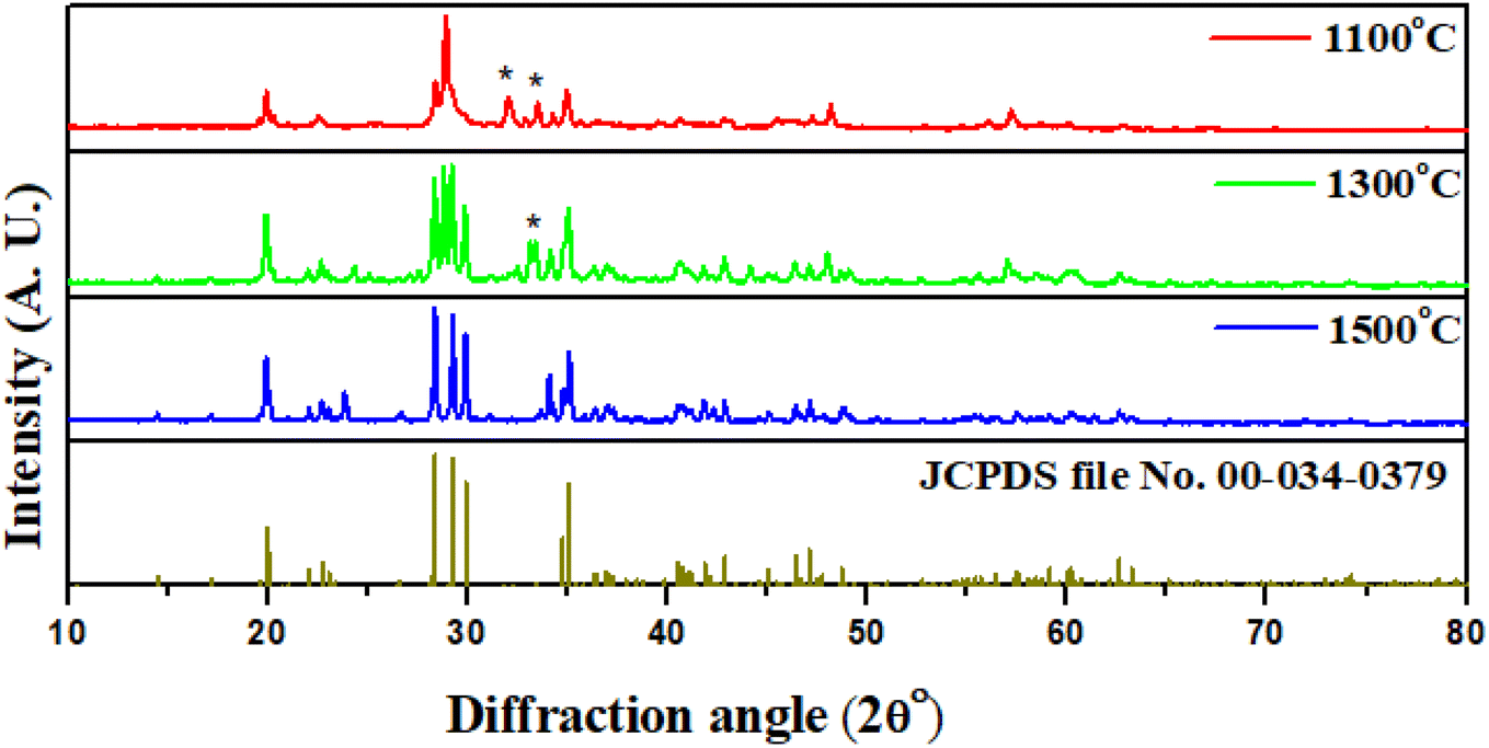
Comparative XRD analysis of the prepared samples at different temperatures, viz. 1100 °C, 1300 °C and 1500 °C, was done. The XRD shows characteristic peaks of the SrAl2O4 monoclinic polymorph (space group P21), characterized by three peaks centered in the 2θ range from 28° to 30° and matched with the SrAl2O4 standard values given in JCPDS (no. 00-34-0379).22–25 The small amount of Eu2+ and Dy3+ ions has not affected the pattern. Here, the XRD peaks analyzed for samples annealed at the abovementioned temperatures are compared, as shown in Fig. 1. The sample prepared at the annealing temperature of 1500 °C has peaks corresponding to pure SrAl2O4 crystal structure, while the sample prepared at 1100 °C shows contamination of diffraction peaks by some impurities, along with the pure SrAl2O4 crystal structure. Through this comparison, it was observed that most diffraction peaks of the pattern corresponding to impurity phases were diminished due to annealing at higher temperature, as shown in Fig. 1. Annealing with higher temperatures led to the disappearance of such phases, yielding the SrAl2O4 phase with higher purity. The purity of the emitted color and persistency in the emitted photons upon UV excitation are very much dependent on these phases present in the developed particles. The details of this result are discussed in the upcoming sections on photoluminescence studies.
 |
| | Fig. 1 Comparative annealing effect on the XRD profile for samples annealed at 1100 °C, 1300 °C and 1500 °C. All the peaks are in good agreement with standard JCPDS data, confirming the dominant phase as SrAl2O4 in the 1500 °C annealed sample. The extra peaks corresponding to impurities are marked by asterisks. | |
The increasing of thermal treatment temperature also enhances the intensity of the SrAl2O4 diffraction peaks, which indicates that with the increase of annealed temperature, the crystal develops more perfectly due to reduction of impurities. Here, the highest diffraction intensity is observed for the sample prepared at 1500 °C. Here, non-appearance of the peaks corresponding to Eu2+/Dy3+ ions indicates that the Eu and Dy are adjusted well in the crystal structure cage of the host lattice. The reason behind this is that the ionic radii of Eu2+ (117 nm) and Dy3+ (0.091 nm) are roughly smaller than that of Sr2+ (0.130 nm), so that Eu2+/Dy3+ ions can easily substitute for Sr2+ sites and have no effect on the SrAl2O4 phase composition.26 Here, through FWHM analysis of each peak, it is also observed that the sample prepared at 1100 °C and 1300 °C annealing temperature has less crystalline properties than the sample prepared at 1500 °C.
4.2 Microstructure analysis
The particle microstructure of samples annealed at different temperatures was investigated by SEM, as shown in Fig. 2. Here, two scales of analysis have been selected. The samples annealed at 1100 °C, 1200 °C, 1300 °C, 1400 °C and 1500 °C shown in Fig. 2 (a–e) use a 200 μm scale bar, while the images in Fig. 2 (f–j) use 20 μm scale bars. In these samples, the color throughout the image is not uniform. The different colored spots have been circled as shown in Fig. 2 (f–j), confirming an inhomogeneous growth of particles. This inhomogeneity was reduced with annealing at higher temperature. Therefore, an inhomogeneous particle distribution was observed, with aggregate structures of irregular shapes and cleavages due to the high calcination temperature. The particle size varies from 7 to 13 μm. This irregularity in the particle shape and size has been investigated in different studies, which found the same particle structures.26–29
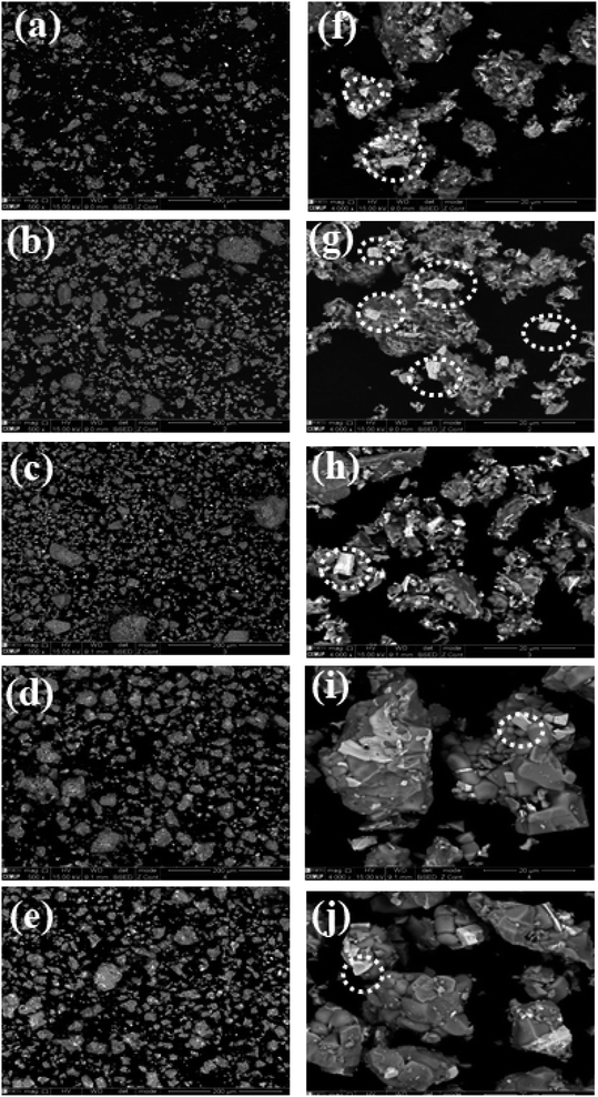 |
| | Fig. 2 SEM microstructures of the set of samples annealed at 1100 °C, 1200 °C, 1300 °C, 1400 °C and 1500 °C at scale bar 200 μm (a–e) and 20 μm (f–j). | |
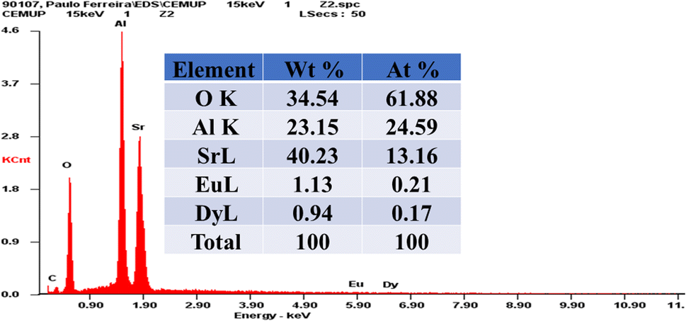
4.2.1 Elemental analysis. Energy-dispersive X-ray (EDX) analysis is a great tool for exact confirmation of the presence of different elements as well as different impurities, if possible.30 In Fig. 3, an EDX image of the sample annealed at 1500 °C is shown. The weight and atomic percentages of different elements of the sample are summarized in the table inset in Fig. 3. Here, the weight percentages of these elements are completely in accordance with the weight taken during synthesis of the present particle. In this EDX analysis, boron is not seen, as it was used in the form of boric acid, which has a very low boiling point (around 300 °C). Our annealing temperatures for different sample preparations were varied from 1100 °C to 1500 °C with an interval of 100 °C. These temperatures are much higher than the boiling point of boric acid. Therefore, boric acid was easily removed due to the temperature and not observed in the present EDX analysis.
 |
| | Fig. 3 EDX analysis of the sample annealed at 1500 °C shows Sr and Al peaks corresponding to the majority composition of the particle, and minor quantities of Eu2+ and Dy3+ ions. Inset: the values of weight and atomic percentages of different elements in the present sample are summarized. | |
4.3 FTIR analysis
A comparative FTIR analysis for samples annealed at 1100 °C and 1500 °C is shown in Fig. 4(a). The wave number range was selected in the range of 400–4000 cm−1. For the sample annealed at 1100 °C, there are several peak bands at 1255 cm−1, 852 cm−1, 773 cm−1, 633 cm−1 and 554 cm−1 with higher percentage transmittance. This again confirms the presence of high-impurity bands in the sample.31,32 In the 1500 °C annealed sample, it was observed that the percentage transmittance values of these bands are much less. The lower transmission values are evidence that the sample purity is very high. Furthermore, the bands at 1255 cm−1 and 554 cm−1 have disappeared, while bands around 2989 cm−1, 2900 cm−1 and 1069 cm−1 have emerged. The broad signals in the range of 900–400 cm−1 can be associated to Sr–O, Al–O, Al–O–H, etc.33 In the inset of Fig. 4(a), the observed peaks are shown more clearly.
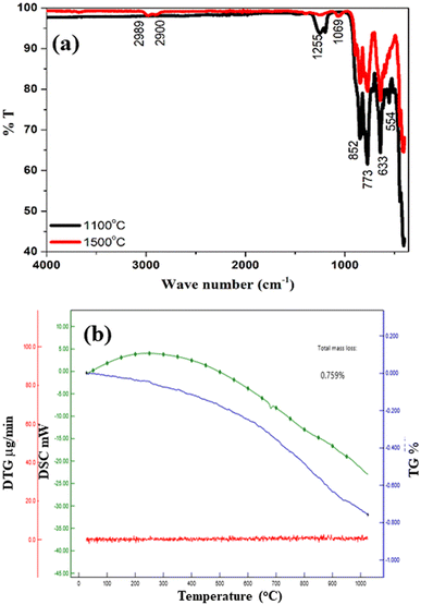 |
| | Fig. 4 (a). A comparative FTIR analysis of SrAl2O4:Eu2+/Dy3+ annealed at two different temperatures. In the inset of (a), the magnified plot in the range of 400–1000 cm−1 is shown. (b) Thermogravimetric analysis (TGA), derivative thermal gravimetric (DTG), and difference scanning calorimetric analysis of the thermally optimized sample (annealed at 1500 °C) in the range of 30–1000 °C. | |
4.4 Thermogravimetric analysis
Thermal stability is an important property that should be retained by an ideal sample.34 For a thermally stable particle, the loss in weight with high temperature should be less.35 Here, to confirm the thermal stability of the present sample, the temperature was changed from room temperature to 1000 °C. As plotted in Fig. 4(b), for a complete change in temperature, the observed loss in total mass was about 0.759%. This loss is much less and considered negligible. This analysis confirms that the present sample is very stable thermally, and there is no effect of high temperature variation on its structural, physical and chemical properties. The DSC analysis shows that with an increase in temperature, the heat difference first increases up to 500 °C, and beyond 500 °C, the value of heat difference is reduced, as shown in Fig. 4(b). At higher temperature, the moisture and impurity content were reduced.
5. Optical analysis
Under the UV excitation, the synthesized samples revealed green photoluminescence, which confirms the purity of the obtained SrAl2O4 phase in the presence of Eu2+/Dy3+ dopants.36 There is a possibility of a change in colour of the photoluminescence emission due to the presence of different dominant phases. For example, SrAl4O7 has orange colour, and SrAl16O25 has red as the dominant colour for the same doping of Eu and Dy ions.37,38
The photoluminescence excitation/emission spectra for each sample are shown in Fig. 5a and b. Corresponding to 528 nm of dominant emission, a search of the excitation spectra was tried for each sample, and it was observed and estimated that the excitation peak is around 400 nm, as shown in Fig. 5(a). Here, a broad excitation peak in the range of 310–480 nm confirms the potential of the present sample to be excited by a selection of multiple wavelengths in the ultraviolet region. At low annealing temperature, excitation peaks were observed at around 350 nm, but with an increase in the annealing temperature, a slight shift was observed in this peak towards 425 nm. This may be due to achievement of purity of the monoclinic SrAl2O4 host crystal structure and reduction of impurities from the organic precursors. Further, under the excitation of 400 nm, all SrAl2O4:Eu2+/Dy3+ samples showed similar emission broad bands (Fig. 5(b)), which exhibit a maximum peak at 528 nm, attributed to the related transition of Eu2+ ions.39,40 Here, the broad excitation/emission peaks are probably due to the thermal vibrations of surrounding ions and local vibration in the host lattice structure.41 According to the emission results, the photoluminescence intensity of the samples increases as the solid-state reaction temperature increases. In a very similar experiment described previously, the glass-forming temperature for the SrO–Al2O3–B2O3 system was around 1500 °C,42 which means reaching a temperature close to the glass-forming one makes the product denser and enhances its luminescence properties. The spectral shape and maximum are mainly the same, with an exception in the samples of 1100 °C and 1300 °C. This is probably due to the presence of other peaks of impurity phases, as identified in the XRD analysis. This was also confirmed in the previous analysis of crystal structure through XRD peaks. Here, the presence of another impurity phase is also responsible for the reduction of emission intensity, as shown in Fig. 5(b), and reduction in persistency, as shown in Fig. 5(d).
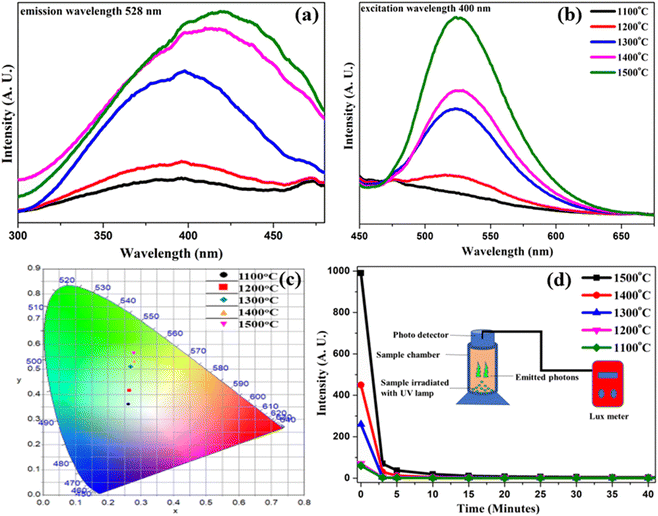 |
| | Fig. 5 (a) Photoluminescence excitation spectra corresponding to emission wavelength at 528 nm; (b) emission spectrum at excitation of 400 nm of synthesized samples SrAl2O4:Eu3+/Dy3+ annealed at temperatures 1100 °C, 1200 °C, 1300 °C, 1400 °C and 1500 °C. (c) Temperature-dependent CIE color coordinate plot. (d) Real-time persistency analysis via calculation of emitted photon intensity with time. Inset shows the experimental arrangement for this calculation. | |
5.1 Annealing-temperature-dependent CIE plot of SrAl2O4:Eu2+/Dy3+
CIE color measurement was done by the spectrophotometric method by using the spectral energy distribution of the given sample, and then calculating the CIE color coordinates, x and y. Host emission chromaticity indicated the emission of green color.43,44 The CIE color coordinate plot for different samples annealed at 1100 °C, 1200 °C, 1300 °C, 1400 °C and 1500 °C is shown in Fig. 5(c). The values of corresponding (x, y) color coordinates and their purity are summarized in Table S2 of the ESI.† Here, under the influence of increasing annealing temperature, the color purity of these samples is also improving. This plot confirms that at the lowest annealing temperature, the CIE coordinate point was around the boundary of the blue and green regions. With increasing annealing temperature, these color coordinates showed the tendency of shifting towards the pure green side. The 1200 °C annealed sample had some improved greenish color coordinate than the previous one, while the other samples annealed at 1300 °C, 1400 °C and 1500 °C successfully maintained their color coordinates in the pure green region. Here, the samples with increased annealing temperature also achieved green color coordinates with higher purity. Therefore, the coordinate corresponding to the highest annealing temperature at 1500 °C had the purest color coordinates. The sample annealed at 1100 °C had the color purity value of 21.4%, while the color purity of the sample annealed at 1500 °C was 55.2%. Thus, future research could investigate the achievement of higher color purity by annealing at higher temperatures. In the ESI,† Table S2 shows the color coordinates and their corresponding color purity extracted from the color calculator software. Here, we suppose that the annealing at higher temperatures, such as 1600 °C, 1700 °C etc., may achieve color coordinates with higher green color purity. Due to lack of higher-temperature annealing facilities, this experiment could not performed.
6. Real-time persistency measurement
A part of the excitation energy is stored by capturing charge carriers (electrons or holes) into traps. The captured electrons can be sequentially released from the traps, leading to long-persistent phosphorescence. As shown in the inset of Fig. 5(d), the powder sample particles were placed in a cylindrical chamber and irradiated with UV light for 10 min, and the decay curve of the afterglow was measured using a lux meter connected to a photodetector at room temperature. Here, each sample annealed at a different temperature was taken one by one and then the decay in luminous intensity was measured with the passage of time. It is observed that the initial intensity was higher for the sample annealed at 1500 °C and lower for the sample annealed at 1100 °C. This luminous intensity value was increased with an increase in annealing temperature, confirming that the crystallinity and purity of SrAl2O4:Eu2+/Dy3+ phase was increased due to the annealing effect. It was also observed that the persistence time for afterglow (AG) was higher for the sample annealed at higher temperature. From this analysis, future studies could possibly aim to achieve longer persistent afterglow using samples annealed at higher temperature. The sample was exposed for 10 minutes at 1000 lux. Table S2,† showing time vs. measured intensity, is given in the ESI.† The data show that the sample annealed at 1100 °C has an afterglow for only 50 minutes, the 1200 °C annealed sample for 60 minutes, the 1300 °C annealed sample for 60 minutes, and the 1400 °C annealed sample for 150 minutes, but the sample annealed at 1500 °C has very long persistency in its afterglow, and that time was measured around 1440 minutes. This result shows that long persistency in afterglow could be achieved through the variation in annealing temperature.
7. Energy level diagram of SrAl2O4:Eu2+/Dy3+
The possible energy level scheme for the explanation of persistency in luminescent emission intensity for the present SrAl2O4:Eu2+/Dy3+ system is shown in Fig. 6.45 At a very high temperature of annealing, the Eu3+ ions are transformed to Eu2+ ions by liberation of holes.46 Through UV excitation, the 400 nm excitation photon is absorbed by Eu2+ ions, and excited-state transition takes place through the 4f7→ (4f6, 5d1) transition. With the incorporation of Dy3+ ion as dopant, the Eu2+ ions' electrons can store more energy, so that the long-persistent luminescence (LPL) ability of SrAl2O4:Eu2+/Dy3+ is enhanced substantially. However, with the introduction of a large number of dysprosium, there is a considerable probability that an oxygen vacancy has a nearby Dy3+ ion within a short range, which allows the transmission of the deep trap energy of oxygen vacancy to the Dy3+ ion. Thus, the dysprosium doping introduces a path to release energy for deep traps caused by oxygen vacancies. Consequently, it strengthens the LPL ability of the material as well. In summary, the mechanism of the LPL in SrAl2O4:Eu2+/Dy3+ is proposed and schematically shown in Fig. 6. On the other hand, in the single doped SrAl2O4:Eu2+, only the oxygen vacancy can store the trapped energy, so that adding Eu2+ ions can no longer raise the storage energy. The electron traps caused by oxygen vacancies distribute in a wide energy range. Besides, the quantity of oxygen vacancies is intrinsically small, so the distance between two nearby oxygen vacancies is large, resulting in the low possibility of energy transfer from the deep trap to a shallow one. Therefore, the persistent luminescence of SrAl2O4:Eu2+ is very low or unobserved.
 |
| | Fig. 6 The representation of the possible excitation-emission process between Dy3+ and Eu2+ ions through an energy level diagram. | |
8. Development of latent fingermarks on different surfaces
In the development of latent fingermarks, the secretory glands of the human body play a very important role. These glands are responsible for different organic and inorganic secretions from body parts and act as primary sources of that development. For example, sweat glands are highly concentrated on the palms. Therefore, the development of fingermarks in crime scenes is not a big task. It is natural. The only big matter of concern is how to detect the exact fingermarks. The primary constituent of latent fingerprints is sweat, which originates from three different types of glands: eccrine, apocrine, and sebaceous glands. Table S3† summarizes the details about the main body secretions in sweat from different parts of the body.47
Sweat (99%), fatty acids, lipids, alkaline salts, amino acids and other organic compounds are sources of moisture in the area used to develop latent fingermarks. The powder dusting of long-lasting powder on these fingermark areas adhere physically due to the pressure deficit in sweat droplets, in which particulates of the fuming powder adhere to the residues left behind by friction ridges on fingers. This occurs only on the lower side of sweat deposition, due to which a curvature of meniscus is formed, which leads to the pressure deficit, causing the particles to adhere to sweat droplets.47 Within a sweat droplet, all molecules move freely due to their chemical potential. When the powder particle is dusted, it dissolves in the sweat residue. Thus, there is considerable loss of freely moving sweat molecules, which results in the pressure deficit inside the droplet.48 On the developed area of latent fingermarks, the fine powder of the optimized particle is dusted. The excess powder is removed using a squirrel-hair brush. This is the easy process for the development of latent fingermarks on any kind of surface.
9. Demonstrations of latent fingermark detection
The detection of latent fingermarks requires the implementation of an external source of excitation, which give emissions in visible range with good emission intensity. Exposure of the fingermark's latent image to UV light results in the formation of trapped electrons on the powder particles. The number of trapped electrons is proportional to the amount of radiation absorbed locally, and the latent image is optically “readable” within a certain timeframe after the exposure. In the next step, the image of the detected area is captured with the help of a digital/DSLR or smartphone camera. In the present demonstration, there are several surfaces selected to investigate the capability of the long-lasting photoluminescent SrAl2O4:Eu2+/Dy3+ particles. These surfaces are of many kinds, including transparent surfaces (biological glass slide and glass beaker), porous surface (piece of black paper), nonporous surface (glass, aluminum foil, iron cylinder and plastic glass), and semiporous surface (plywood surface). In addition to plane surfaces, fingermark detection on curved surfaces like iron cylinder and glass beaker has also been tried. To study the effect of the background color, colored background surfaces were also selected.
9.1 Detection of latent fingermarks on nonporous surfaces
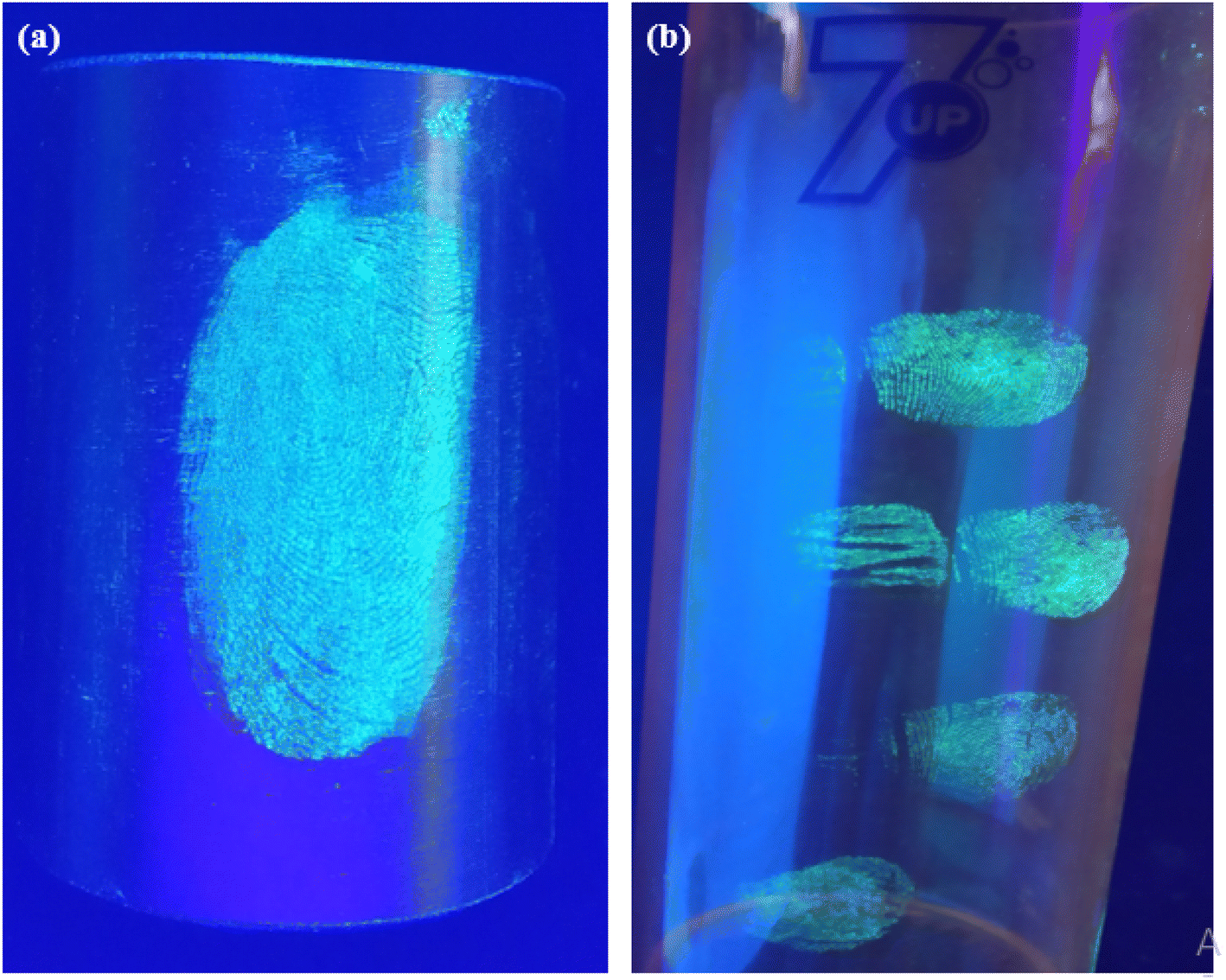
A range of nonporous surfaces has been selected. These surfaces include glass, aluminum foil, iron cylinder and plastic glass. Fig. 7(b) shows a transparent biological glass slide surface. On this surface, the latent fingermark is clearly developed and detected. The other surfaces are very tough for latent fingermark development and detection, as the surfaces of wood ply, black paper, iron cylinder and plastic glass are very rough. Previous experiments, e.g., V. Sharma et al., did latent fingermark detection with Sr4Al14O25:Er2+/Dy3+ on almost all-smooth surfaces, such as soft drink can, pet bottle etc.17 In contrast, we have chosen a variety of surfaces. The ridge patterns are well specified. The quality of the developed fingermarks shows that the powder has spread well on the surfaces. Different identifying corners, like the centre of the fingermark, junction of two patterns, etc. are identified well. Another surface in this category was a glass beaker. As shown in Fig. 7(c), the fingermarks apart from the thumb impression—the marks of the index, middle, ring and little fingers—were developed and detected. Generally, the ridge patterns of these fingers are not as well separated as those of the thumb. Therefore, it is a very tough task to develop and detect the latent fingermarks of these fingers. Here, we have successfully achieved this. In Fig. 7(c), the pattern is well identified. Also, some extra marks on the finger area have been detected. The detection of extra marks is quite beneficial, as these marks create greater trust in the evidence. Another surface in this category was selected, a surface of aluminium foil. On this surface, the quality of fingermarks developed is also very good and suitable for crime evidence. The development of latent fingermarks on an iron cylinder surface was another surface in this category. The fingermark development on this surface is quite hard, because this kind of surface is not very smooth and is round in shape. Here, as shown in Fig. 8(a), the developed fingermark is a little unclear, but one can identify this pattern very well. Therefore, we can say that the successful development and detection of latent fingermarks have also been achieved. The last surface in this set was a plastic glass bottle. On this surface, we tried to impress and develop the four fingers apart from the thumb. This surface was little bit harder, as the diameter of this surface was not identical and this surface was not as smooth as the glass beaker that was previously selected. Another problem was the background color. But the fingermark on this surface is still good, as shown in Fig. 8(b).
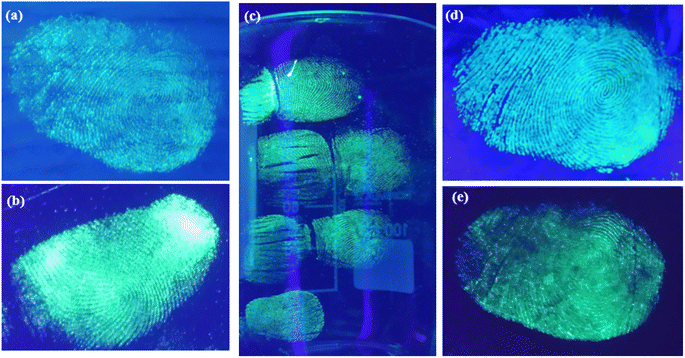 |
| | Fig. 7 Detection of latent fingermarks on (a) wood ply, (b) biological glass slide (c) laboratory glass beaker of 100 ml volume, (d) aluminum foil and (e) black paper sheet after exposure to UV lamp. | |
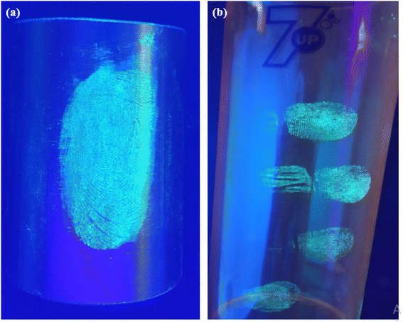 |
| | Fig. 8 Detection of latent fingermarks on (a) an iron cylinder surface and (b) a plastic bottle surface by exposure with a UV lamp. | |
9.2 Detection of latent fingermarks on semiporous surfaces
In Fig. 7(a), the result of latent fingermark detection on the semiporous plywood surface is shown. Here, the fingermarks of a 32-year-old adult are developed. This surface was not smooth but very rough. Therefore, the development of fingermarks was hard on this surface too. Here, the ridge pattern in this image is very clear. One can easily distinguish different patterns of fingermarks in this image. For example, in the center of image, the central pattern of fingermarks is clearly observed. Apart from the central pattern, some other patterns like core, end of a pattern, matching of two patterns, etc., are well observed.
9.3 Detection of latent fingermarks on porous surface
As a porous surface, a piece of paper was selected. The development of fingermarks was also hard, as the surface was totally rough. As shown in Fig. 7(d), the developed fingermarks have been visualized. Here, the pattern of developed fingermarks is completely identified. Only a portion in middle of the developed area could not be identified well. This is a minor issue that can be improved by optimization of the development and detection techniques.
The experiment related to the aging effect on the developed fingermarks was also performed. All the fingermark detections were again performed after a long duration of six months, and every time, we detected the fingermarks without any difficulties. The emission color, intensity, persistency etc. was the same every time, which proves the reproducibility of the results. Overall, these demonstrations of development and detection of latent fingermarks on different difficult surfaces prove that the present long-lasting powder has potential application in the detection of latent fingermarks as evidence from a crime scene. Furthermore, the fingerprints developed using the present powder could be lifted by scotch tape and preserved in the evidence bag, and then re-excited as required.
10. Conclusions
In conclusion, we have completed new investigations on the SrAl2O4:Eu2+/Dy3+ photoluminescent material. The effect of annealing temperature on the crystal structure, particle morphology, photoluminescence and persistency of afterglow was studied on a broad scale for the first time. With an increase in the temperature of annealing, the purity of luminescence and persistency of long afterglow can both be achieved. Our results reveal that higher reaction temperature is needed to get higher photoluminescence intensity. Accurate times for persistency have been measured for the first time using a lux meter. The results indicate that the present persistent particles can be used as a potential candidate for the detection of latent fingerprints. Therefore, the suitability of the optimized fine powder in the detection of latent fingermarks on different difficult surfaces has also been demonstrated successfully.
Conflicts of interest
There are no conflicts to declare.
Acknowledgements
This work was funded by the European Structural and Investment Funds in the FEDER component, through the Operational Competitiveness and Internationalization Programme (COMPETE 2020) Project No. 23910 “Night Vision” (POCI-01-0247-FEDER-023910). A. N.-M. and D. C. acknowledge Ferreira Martins e Filhos – Madeiras e Derivados S. A. for the support. As a part of ethical policy, fresh fingermarks were collected from healthy donor (A. Kumar) aged 32 years, who is also one of the co-authors of this article, with her prior written consent. We would also like to acknowledge FCT (Fundação para a Ciência e Tecnologia), the National budget of project UIDB/00081/2020.
References
- S. Oden and B. V. Hofsten, Nature, 1954, 173, 449 CrossRef CAS PubMed.
- T. C. Fung, K. Grimwood, R. Shimmon, X. Spindler, P. Maynard, C. Lennard and C. Roux, Forensic Sci. Int., 2011, 212, 143 CrossRef CAS PubMed.
- M. Tahtouh, J. R. Kalman and B. J. Reedy, J. Polym. Sci., Polym. Chem., 2011, 49, 257 CrossRef CAS.
- F. G. Kendall and B. W. Rehn, J. Forensic Sci., 1983, 28, 777 Search PubMed.
- G. S. Sodhi and J. Kaur, Forensic Sci. Int., 2001, 120, 172 CrossRef CAS PubMed.
- M. J. Choi, T. Smoother, A. A. Martin, A. M. Mc Donagh, P. J. Maynard, C. Lennard and C. Roux, Forensic Sci. Int., 2007, 173, 154 CrossRef CAS PubMed.
- M. Saif, M. Shebla, A. I. Nabeelb, R. Shokrya, H. Hafez, A. Mbarekd, K. Damake, R. Maalej and M. S. A. A. Mottalebg, Sens. Actuators, B, 2015, 220, 162 CrossRef CAS.
- M. Saif, J. Lumin., 2013, 135, 187 CrossRef CAS.
- S. K. Singh, K. Kumar and S. B. Rai, Appl. Phys. B, 2009, 94, 165 CrossRef CAS.
- M. Wang, M. Li, A. Yu, J. Wu and C. Mao, ACS Appl. Mater. Interfaces, 2015, 51, 28110 CrossRef PubMed.
- R. Chen, Y. Hu, L. Chen, X. Wang, Y. Jin and H. Wu, Ceram. Int., 2014, 40, 8229 CrossRef CAS.
- W. He, T. S. Atabaev, H. K. Kim and Y. H. Hwang, J. Phys. Chem. C, 2013, 117, 17894 CrossRef CAS.
- J. Ueda, K. Aishima, S. Nishiura and S. Tanabe, Appl. Phys. Express, 2011, 4, 042602 CrossRef.
- Y. Tang, H. Song, Y. Su and Y. Lv, Anal. Chem., 2013, 85, 11876 CrossRef CAS PubMed.
- M. Li, X. Zhou, Y. Zhang, F. Jiang, S. Sha, S. Xu and S. Li, Ceram. Int., 2020, 46(16), 25399–25404 CrossRef CAS.
- T. Zheng, S. Ye, D. Wang, K. Li, Y. Wang, Z. Liu and H. J. Wang, Chin. Ceram. Soc., 2015, 2, 17–23 Search PubMed.
- V. Sharma, A. Das, V. Kumar, O. M. Ntwaeaborwa and H. C. Swart, J. Mater. Sci., 2014, 49, 2225 CrossRef CAS.
- L. Lui, Z. Zhang, L. Zhang and Y. Zhai, Forensic Sci. Int., 2009, 183, 45–49 CrossRef PubMed.
- J. Botterman, J. J. Joos and P. F. Smet, Phys. Rev. B: Condens. Matter Mater. Phys., 2014, 90(8), 1–15 CrossRef.
- V. P. Singh, S. B. Rai, H. Mishrac and C. Rath, Dalton Trans., 2014, 43, 205309 Search PubMed.
- K. S. Hwang, B. A. Kang, S. D. Kim, S. Hwangbo and J. T. Kim, Bull. Mater. Sci., 2011, 34, 1059 CrossRef CAS.
- D. S. Kshatri and A. Khare, J. Lumin., 2014, 155, 257 CrossRef CAS.
- X. Lyu, Mater. Chem. Phys., 2005, 93, 526 CrossRef.
- X. Zhang, H. Zou, C. Xu, Z. An, R. Dong, K. Zheng, Y. Sheng and Y. Son, Opt. Mater., 2019, 89, 512 CrossRef CAS.
- N. K. Giri, S. K. Singh, D. K. Rai and S. B. Rai, Appl. Phys. B, 2010, 99, 271 CrossRef CAS.
- K. Fukuda and K. Fukushima, Crystal structure of hexagonal SrAl2O4 at 1073 K, J. Solid State Chem., 2005, 178, 2709 CrossRef CAS.
- J. Renaud, N. Gnidakouong and G. J. Yun, Ceram. Int., 2019, 45(2), 1794 CrossRef.
- N. Yu, F. Liu, X. Li and Z. Pan, Appl. Phys. Lett., 2009, 95, 231110 CrossRef.
- J. Li, Y. Zhao, M. Ge, S. Fu and T. Lin, J. Rare Earths, 2016, 34, 653 CrossRef CAS.
- A. Kumar, S. P. Tiwari, K. Kumar and V. K. Rai, Spectrochim. Acta, Part A, 2016, 167, 134 CrossRef CAS PubMed.
- A. Kumar, J. C. G. Esteves da Silva, K. Kumar, H. C. Swart, S. K. Maurya, P. Kumar and S. P. Tiwari, Mater. Res. Bull., 2019, 112, 28 CrossRef CAS.
- A. Kumar, M. H. M. Couto, S. P. Tiwari, K. Kumar and J. C. G. Esteves da Silva, ChemistrySelect, 2018, 38, 10566 CrossRef.
- K. Djebaili, Z. Mekhalif, A. Boumaza and A. Djelloul, J. Spectrosc., 2015, 868109, 1 Search PubMed.
- A. Kumar, S. P. Tiwari, K. Kumar and J. C. G. Esteves da Silva, Mater. Res. Express, 2019, 6, 10 Search PubMed.
- G. J. Hernández-Alvarado, S. M. Montemayor, I. Moggio, E. Ariasa, E. Trujillo-Vázquez, J. A. Díaz-Guillén, C. A. Ávila-Orta and O. S. Rodríguez-Fernández, Ceram. Int., 2018, 44, 12789 CrossRef.
- B. g. Zhai, Q. l. Ma and Y. M. Huang, Key Eng. Mater., 2013, 538, 58 Search PubMed.
- P. Escribano, M. Marchal, M. L. Sanjuan, P. Alonso-Gutierrez, B. Julian and E. Cordoncillo, J. Solid State Chem., 2005, 178, 1978 CrossRef CAS.
- R. Zheng, L. Xu, W. Qin, J. Chen, B. Dong, L. Zhang and H. Song, J. Mater. Sci., 2011, 46, 7517 CrossRef CAS.
- A. M. Kaczmarek, D. Ndagsi and R. Van Deun, Dalton Trans., 2016, 45, 16231 RSC.
- S. Ferdov, R. A. S. Ferreira and Z. Lin, Chem. Mater., 2006, 18, 5958 CrossRef CAS.
- L. Liu, Z. Zhang, L. Zhang and Y. Zhai, Forensic Sci. Int., 2009, 183, 45 CrossRef CAS PubMed.
- T. Nakanishi, Y. Katayama and J. Ueda, et al., J. Ceram. Soc. Jpn., 2011, 119(1391), 609 CrossRef CAS.
- A. Kumar, G. Kedawat, P. Kumar, J. Dwivedia and B. K. Gupta, New J. Chem., 2015, 39, 3380 RSC.
- L. Zhang, S. Lyu, Z. Chen and S. Wang, Nanomaterials, 2018, 8, 352 CrossRef PubMed.
- P. Zeng, X. Wei, M. Yin and Y. Chen, J. Lumin., 2018, 199, 400–406 CrossRef CAS.
- P. J. Dereń, D. Stefańska, M. Ptak and P. Wiśniewski, J. Phys. Chem. C, 2021, 125(44), 24505–24514 CrossRef.
- A. Arshad, M. A. Farrukh, S. Ali, M. K. Rahman and M. A. Tahir, J. Forensic Sci., 2015, 60, 1182 CrossRef CAS PubMed.
- G. Swati, S. Bishnoi, P. Singh, N. Lohia, V. V. Jaiswal, M. K. Dalai and D. Haranath, Anal. Methods, 2018, 3(10), 308–313 RSC.
|
| This journal is © The Royal Society of Chemistry 2023 |
Click here to see how this site uses Cookies. View our privacy policy here. 
 Open Access Article
 This Open Access Article is licensed under a Creative Commons Attribution-Non Commercial 3.0 Unported Licence
 *ab,
Diana M. A. Cristaac,
Ara Núñez-Montenegroac,
Joaquim C. G. Esteves da Silva
*ab,
Diana M. A. Cristaac,
Ara Núñez-Montenegroac,
Joaquim C. G. Esteves da Silva