
 Open Access Article
 This Open Access Article is licensed under a Creative Commons Attribution-Non Commercial 3.0 Unported Licence
Developing efficient CuO nanoplate/ZnO nanoparticle hybrid photocatalysts for methylene blue degradation under visible light
Nguyen Dac Diena,
Pham Thi Thu Hab,
Xuan Hoa Vu *c,
Tran Thu Trangc,
Trinh Duc Thanh Giangd and
Nguyen Thi Dungc
*c,
Tran Thu Trangc,
Trinh Duc Thanh Giangd and
Nguyen Thi Dungc
aFaculty of Occupational Safety and Health, Vietnam Trade Union University, 169 Tay Son Street, Dong Da district, Ha Noi city 100000, Vietnam
bFaculty of Chemistry, TNU-University of Sciences, Tan Thinh ward, Thai Nguyen city 24000, Vietnam
cInstitute of Science and Technology, TNU-University of Sciences, Tan Thinh ward, Thai Nguyen city 24000, Vietnam. E-mail: hoavx@tnus.edu.vn
dDao Duy Tu High School, Chu Van An road, Hoang Van Thu ward, Thai Nguyen city 24000, Vietnam
First published on 16th August 2023
Abstract
CuO/ZnO nanocomposites with different components can overcome the drawbacks of previously used photocatalysts owing to their promotion in charge separation and transportation, light absorption, and the photo-oxidation of dyes. In this study, CuO nanoplates were synthesized by the hydrothermal method, while ZnO nanoparticles were fabricated by the precipitation method. A series of CuO/ZnO nanocomposites with different ZnO-to-CuO weight ratios, namely, 2![[thin space (1/6-em)]](https://www.rsc.org/images/entities/char_2009.gif) :8, 4:6, 5:5, 6:4, and 8:2 were obtained via a mixing process. X-ray diffraction patterns confirmed the presence of hexagonal wurtzite ZnO and monoclinic CuO in the synthesized CuO/ZnO nanocomposites. Scanning electron microscopy showed the dispersion of ZnO nanoparticles on the surface of CuO nanoplates. Ultraviolet-visible absorption spectra exhibited a slight red-shift in the absorption edge of binary oxides relative to pure ZnO or CuO. All samples were employed for the photocatalytic degradation of methylene blue (MB) under visible light irradiation. The composite samples exhibited enhanced photocatalytic performance compared with pristine CuO or ZnO. This study aimed to examine the effect of the ZnO-to-CuO weight ratio on their photocatalytic performance. The results indicated that among all the synthesized nanocomposites and pristine oxides, the nanocomposite with ZnO and CuO in a proportion of 4:6 shows the highest photodegradation activity for the removal of MB with 93% MB photodegraded within 60 min at an initial MB concentration of 5 ppm. The photocatalytic kinetic data were described well by the pseudo-first-order model with a high correlation coefficient of 0.95. The photocatalytic mechanism of the mixed metal oxide was proposed and discussed in detail. The photodegradation characteristic of CuO/ZnO nanostructures is valuable for methylene blue degradation from aqueous solutions as well as environmental purification in various fields.
:8, 4:6, 5:5, 6:4, and 8:2 were obtained via a mixing process. X-ray diffraction patterns confirmed the presence of hexagonal wurtzite ZnO and monoclinic CuO in the synthesized CuO/ZnO nanocomposites. Scanning electron microscopy showed the dispersion of ZnO nanoparticles on the surface of CuO nanoplates. Ultraviolet-visible absorption spectra exhibited a slight red-shift in the absorption edge of binary oxides relative to pure ZnO or CuO. All samples were employed for the photocatalytic degradation of methylene blue (MB) under visible light irradiation. The composite samples exhibited enhanced photocatalytic performance compared with pristine CuO or ZnO. This study aimed to examine the effect of the ZnO-to-CuO weight ratio on their photocatalytic performance. The results indicated that among all the synthesized nanocomposites and pristine oxides, the nanocomposite with ZnO and CuO in a proportion of 4:6 shows the highest photodegradation activity for the removal of MB with 93% MB photodegraded within 60 min at an initial MB concentration of 5 ppm. The photocatalytic kinetic data were described well by the pseudo-first-order model with a high correlation coefficient of 0.95. The photocatalytic mechanism of the mixed metal oxide was proposed and discussed in detail. The photodegradation characteristic of CuO/ZnO nanostructures is valuable for methylene blue degradation from aqueous solutions as well as environmental purification in various fields.
1. Introduction
The water pollution issue has recently attracted the attention of governments, industries, civil society, and the scientific community worldwide. Several types of inorganic and organic compounds have been devastating the world's ecology. Nowadays, synthetic dyes are commonly used in several industrial processes, and the residual dyes are released into water resources.1 Textile dyes are the greatest source of organic compounds that contaminate the water bodies. They may cause serious problems to aquatic life and human beings.2 An advanced oxidation process based on nanomaterials' photocatalytic effect is considered the best technology for efficient wastewater treatment owing to its environmental friendliness. Based on the generation of hydroxyl radicals ·OH, this process converts the pollutants in water into intermediate products that are not as toxic as dyes.3 Most of the materials explored for photocatalytic applications are semiconductors4 owing to their potential to exploit ultraviolet (UV) and visible light.5 They are non-toxic, cheap, and chemically stable and can efficiently reduce chemical and biological pollutants.6 Among various semiconductors, zinc oxide (ZnO) and copper(II) oxide (CuO) have attracted considerable interest owing to their environmentally benign nature, high stability, low-cost preparation, and high catalytic performance.7 However, the wide bandgap of semiconductor photocatalysts allows them to be used only under ultraviolet (UV) irradiation.8–10 Heterogeneous photocatalysts including CuO–ZnO nanobullets,11 ZnO/CuO/MoO3 nanorods,12 Fe2O3–ZnO composites,13 SnO2/reduced graphene oxides,14 ZnO/CdS nanofibers,15 ZnO/CeO2 heterojunctions,16 and TiO2/Bi2O3/CuO17 from metal oxides for wastewater treatment have been investigated as the most efficient materials for industrial water purification owing to their potential for the degradation of toxic organic pollutants. Among those semiconductor heterostructures, the CuO/ZnO nanocomposite possesses high photocatalytic performance because of its large surface area and simple synthesis methods.18 Among the physical and chemical methods available to prepare nanomaterials, hydrothermal and precipitation techniques are considered simple, inexpensive, versatile and environmentally friendly.19,20 Nanostructured materials have a high specific surface area with a lot of active sites, which facilitate the adsorption and mineralization of pollutants. The light irradiation produced photoinduced charge carriers and reactive oxygen species (ROS) such as oxygen and hydroxyl radicals. However, the bandgap of ZnO is approximately 3.37 eV, which is relatively wide, and hence, UV light is required to generate electrons and holes. The rapid recombination of electron–hole pairs restricted the practical use of pristine ZnO nanomaterials.21 Coupling ZnO with other metals or metal oxides can improve the performance of ZnO, extend the lifetime of photo-generated electron–hole pairs and achieve visible-light-driven photocatalysts.22,23 The photocatalyst is a promising alternative for environmental detoxification as well as wastewater decontamination.24Zinc oxide (ZnO) is known as an n-type semiconductor with a large direct bandgap of 3.37 eV and an exciton binding energy of ∼60 meV,25 thermal stability, and the ability to form heterojunction nanomaterials with other metal oxides.12,13,26 It was successfully used for different applications including solar cells,27 gas sensors,28 biosensors,29 antibacterial agents,30 optoelectronic devices31 and the photocatalytic degradation of dyes.32 However, the practical use of ZnO alone as a photocatalyst is eclipsed because of its large bandgap, poor visible light harvesting, poor carrier separation, and fast recombination rate and short life of photogenerated electron–hole pairs.33 To overcome these shortcomings, much research efforts have been devoted to enhance the life span of photoinduced species and improve the light absorption capacity and electron–hole separation via the coupling of ZnO with other metal oxides such as Fe2O3, TiO2, and MoO3.12,13,26,34 The combination led to higher light adsorption in the visible range, and the charge migration and separation can be improved owing to the restriction of the electron and hole accumulation in the semiconductor.35 Cupric oxide (CuO) is a p-type semiconductor with a narrow bandgap (2.6 eV), remarkable electrical conductivity, and high stability in the air.36 CuO nanostructures have exhibited notable photocatalytic performance for dye degradation in the UV and visible light region.37 However, CuO revealed quite low photocatalytic efficiency due to the rapid recombination of electrons and holes.38 CuO is an ideal candidate for integration with ZnO-based photocatalysts due to its potential to enable effective charge separation in transferring photoexcited electrons from the high conduction band to the low one.11,19,35,39 Recently, the use of CuO/ZnO nanomaterials for photocatalytic application was more competitive than other hybrids.40,41 CuO can improve the photocatalytic performance of ZnO via promoting the separation of electron–hole pairs on the ZnO surface and improving light energy harvesting in the visible region.42,43 In recent reports, CuO/ZnO combination has been focused as a photocatalyst for degrading several organic pollutants. For instant, M. Nami et al. fabricated a ZnO flower-CuO patch nanocomposite by anodic oxidation of alpha brass; the obtained ZnO–CuO nanocomposite could degrade phenol under visible light irradiation, where 49% phenol was degraded after 5 h irradiation.44 K. Salehi et al. synthesized a CuO–ZnO nanocomposite by a hydrothermal method at 150 °C and autogenous pressure; the prepared nanocomposite was utilized for the photocatalytic degradation of aromatic Direct Blue 71 dye (DB71) under natural sunlight.45 C. Chen et al. fabricated ZnO/CuO hollow microspheres by a self-assembly hydrothermal method and achieved enhanced photodegradation of Rhodamine B (RhB) under natural sunlight illumination.46 The better photocatalytic performance of the heterojunction between CuO and ZnO is attributed to the increased surface area, prevents the photogenerated charge carrier recombination, and accelerated migration of electrons and holes on the catalyst surface.47 Similar enhancement in the photocatalytic activity of different CuO/ZnO heterojunctions has been reported in numerous accounts.48–50
Methylene blue (MB), also known as methylthionine chloride (C16H18ClN3S), is a cationic thiazine dye with a stable molecular structure and non-biodegradable nature. It has been one of the most commonly used substrates for dyeing cotton, wool, silk, and other synthetics, and hence, it presents widespread in the effluents of the chemical industry into the land and water without proper treatment.51 It is reported that MB introduced to natural water resources without adequate treatment will be dangerous to human life, containing genotoxicity and carcinogenicity.52 MB causes human health problems such as nausea, restless breathing, extreme sweating, mental disorder, eye irritation, dermal change, oxidation stress, cyanosis, diarrhea, and cardiovascular disease.13 MB in water bodies also inhibits light penetration and, subsequently, decreases photosynthetic activity, leading to oxygen deficiency in the aquatic environment and affecting living aquatic animals and plants.53 Therefore, it is essential to remove MB from wastewater before discharge to eliminate the harmful impacts of wastewater containing MB on living creatures and human beings.54 Up to now, several treatment techniques including ion-exchange, biological treatment, physicochemical precipitation, membrane process, and sonocatalytic and adsorption methods have been studied critically to remove MB from the effluents before releasing them to the environment.52,55 Of these techniques, photocatalysis has attracted considerable scientific attention due to its simple operation, high efficiency, complete mineralization in degrading recalcitrant compounds and less likelihood of leading secondary pollution.56 Several different photocatalysts have been utilized for MB degradation from aqueous solutions such as CdS, SnO2/rGO, SnO2, Fe2O3/GO, Fe2O3/ZnO, graphene, and TiO2.13,53,57 Recently, metal oxide nanomaterials have gained significant research interest owing to their exceptionally high specific surface area and high photocatalytic ability. For example, H. Ullah et al. synthesized cadmium sulfide (CdS) nanorods and nanowires to photo-degrade MB under solar light; CdS nanowires show more pronounced photocatalytic activity than that of CdS nanorods.58 P. V. Tuan et al. prepared SnO2/reduced graphene oxide (rGO) nanocomposites by a hydrothermal method to decompose MB under visible light by more than 90%, while SnO2 decomposed MB by only approximately 30%.14 Various methods including composite formation,13,15,59 addition of metal ion dopants,9,56,60 and blending metal oxide8,12,13 were developed to enhance the photocatalytic performance. Some researchers have combined CuO with ZnO to produce a photocatalyst for the degradation of pollutants such as methylene blue,4,11 Rhodamine B,7,43 Rhodamine 6G,36 methyl orange,36 ciprofloxacin,39 Brilliant Blue,35 Direct Blue,45 Congo Red (CR), tetracycline (TC),49 phenol red,61 and 4-nitrophenol.62 CuO/ZnO materials have been reported as promising photocatalysts to degrade MB since they bear multiple active sites with tunable compositions. For instance, M. S. AlSalhi et al. prepared composite CuO/ZnO nanoparticles via a precipitation route to degrade MB under solar light irradiation, and the maximum degradation efficiency of 98.07% was achieved at 150 min of irradiation time.48 M. Nami et al. fabricated ZnO nanorods/CuO nanourchins by chemical bath precipitation; the obtained composite can completely degrade MB within 4 h under visible light irradiation, about 12 times faster than ZnO.20 However, to the best of our knowledge, studies on combining CuO nanoplates and ZnO nanoparticles to photodegrade MB from aqueous solutions are quite scarce.
This article focuses on the properties of CuO nanoplate/ZnO nanoparticle composites, the technique for synthesizing them and their application in the photodegradation and mineralization of organic pollutants. Here, CuO nanoplates were prepared by a simple low-temperature hydrothermal method using CuSO4 as a copper precursor and NaOH as a basic medium, which favored the precipitation of Cu(OH)2, while ZnO nanoparticles were fabricated by a precipitation method using Zn(NO3)2 and (NH4)2CO3 as starting agents. Furthermore, the CuO/ZnO nanocomposites were synthesized by a simple mechanical mixing technique with the aim of enhancing the efficiency of the photocatalytic activity toward methylene blue (MB). The nanocomposites were characterized by scanning electron microscopy (SEM), X-ray diffraction (XRD), energy-dispersive X-ray spectroscopy (EDS), ultraviolet-visible (UV-Vis) absorption spectroscopy, Fourier transform infrared (FTIR) spectroscopy and photoluminescence (PL) spectroscopy. The photocatalytic activity of the obtained products was investigated toward the degradation of methylene blue under visible light irradiation. Here, the coupling of two metal oxides with different bandgap energies transformed a wide-bandgap semiconductor into a visible light active photocatalyst. CuO/ZnO heterojunctions significantly improved the photocatalytic performance of pristine CuO or ZnO. This composite resolves the shortcoming associated with the low photocatalytic activity of CuO when used alone and the instant recombination of light-induced electrons and holes in ZnO. This p–n-type heterojunction promotes the separation between photogenerated charge carriers and inhibits their recombination, consequently accelerating the photocatalytic reaction. The effect of weight ratio between CuO and ZnO on the photocatalytic capacity was investigated. This work also discusses the proper photocatalytic degradation mechanism of MB.
2. Experimental
2.1. Chemicals
Zinc nitrate hexahydrate Zn(NO3)2·6H2O, ammonium carbonate trihydrate (NH4)2CO3·3H2O, absolute ethanol (C2H5OH), sodium hydroxide (NaOH), and copper sulfate pentahydrate (CuSO4·5H2O) were purchased from Sigma-Aldrich and used as synthetic precursors for CuO/ZnO. All the chemicals were of analytical grade and used as received without further purification. Methylene blue (MB, C16H18ClN3S) was used as the target organic pollutant in the photocatalytic experiment. Double-distilled water was used to prepare all solutions.2.2. Synthesis of ZnO nanoparticles
Pristine ZnO nanoparticles were fabricated by a precipitation method using zinc nitrate hexahydrate and ammonium carbonate trihydrate. This method is based on the sequential hydrolysis of metal precursors to produce a metal salt solution. In a typical reaction process, 3.7138 g Zn(NO3)2·6H2O was dispersed in a container containing 200 ml distilled water as a solvent to form a 0.0625 M Zn(NO3)2 solution. Similarly, 2.248 g (NH4)2CO3·3H2O was dispersed in 240 ml distilled water to obtain a 0.0625 M (NH4)2CO3 solution using a magnetic stirrer for 15 min at ambient temperature. Then, an ammonium carbonate solution was added dropwise into a zinc nitrate solution under continuous stirring for 1 h. Two precursor salts react to form zinc carbonate using the equation:| Zn(NO3)2 + (NH4)2CO3 → ZnCO3 + 2NH4NO3 | (1) |
The aggregated crystal of zinc carbonate was subsequently vacuum filtrated and washed repeatedly with deionized water and ethanol to wipe out the NH4NO3 by-product, (NH4)2CO3 residue, and solvent. The obtained solid was dried at 80 °C overnight to completely remove the remnant molecules. Obtained ZnCO3 was calcined at 500 °C for 2 h to remove CO2 from ZnCO3 molecules:
| ZnCO3 → ZnO + CO2 | (2) |
The obtained ZnO nanoparticles were retained in a plastic tube with a sealable lid to avoid the intrusion of the atmosphere into the tube. The product exhibits high porosity and large surface area with enhanced adsorption capability, which can facilitate the degradation of dyes. Fig. 1 illustrates the precipitation method to synthesize ZnO nanoparticles. Pristine ZnO was used to evaluate the photocatalytic activity of the CuO/ZnO nanocomposites.
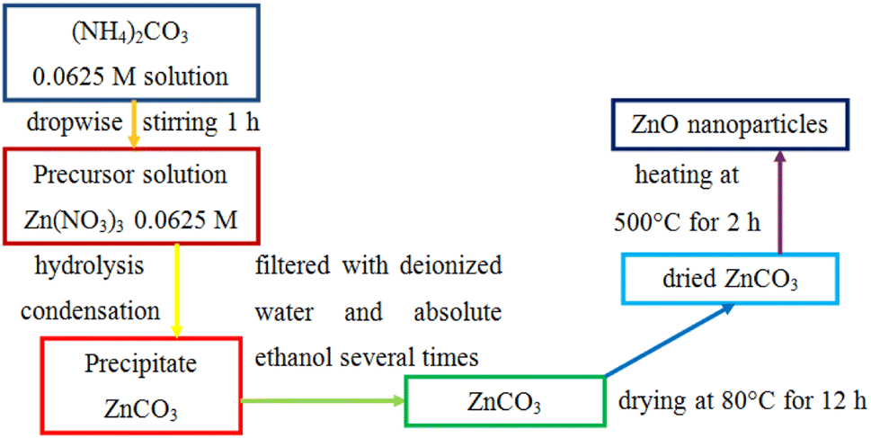 | ||
| Fig. 1 Illustration of the precipitation method to fabricate ZnO nanoparticles. | ||
2.3. Synthesis of CuO nanoplates
CuO nanoplates were synthesized by a hydrothermal method. The hydrothermal process involves heterogeneous reactions in an aqueous medium at a temperature exceeding 100 °C (water's boiling point) and a pressure higher than 1 bar in a sealed autoclave. First, 0.0375 M CuSO4 solution was prepared by dispersing 2.814 g of copper(II) sulfate pentahydrate in 300 ml of distilled water under magnetic stirring until the reagent was completely dissolved. The Cu(OH)2 precipitation was done by dropwise addition of 0.15 M NaOH along with constant stirring for 30 min till the volume of NaOH solution reached 150 ml:| CuSO4 + 2NaOH → Cu(OH)2 + Na2SO4 | (3) |
Then, 200 ml mixed solution was poured into a 250 ml Teflon-lined stainless-steel autoclave and placed in an electric oven at 120 °C for 10 h. After naturally cooling down to room temperature, a light-blue color solid was obtained, filtrated, and washed with distilled water and absolute ethanol several times to remove the remnants. The wet gel of Cu(OH)2 was dried at 80 °C for 24 h and finally calcined at 300 °C for 4 h to form CuO:
| Cu(OH)2 → CuO + H2O | (4) |
Fig. 2 illustrates the hydrothermal method to prepare CuO nanoplates.
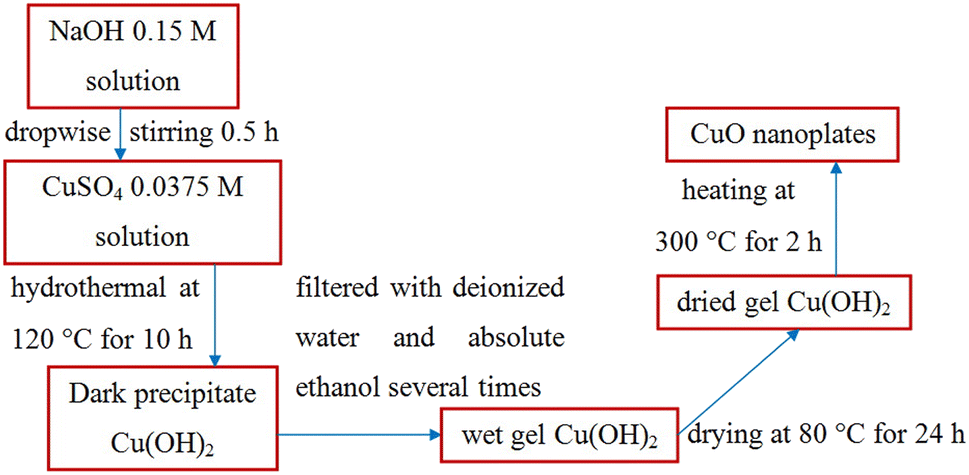 | ||
| Fig. 2 Illustration of the hydrothermal synthesis of CuO nanoplates. | ||
2.4. Synthesis of CuO/ZnO composites
To combine ZnO nanoparticles with CuO nanoplates to form CuO/ZnO nanocomposites, the dried CuO, ZnO powders were mixed in distilled water at five mass ratios of ZnO:CuO, namely, 2:8, 4:6, 5:5, 6:4 and 8:2 through magnetic stirring for 15 min. The obtained solutions were dried at 80 °C until the water evaporated completely and kept in a sealed bag before further study.
2.5. Characterization
Scanning electron microscopy (SEM, Hitachi S4800, Japan) was applied to characterize the surface morphologies and particle sizes of the fabricated nanostructures. Energy-dispersive X-ray spectroscopy (EDS, Hitachi SU 8020, Japan) was performed to confirm the elemental composition and purity of the samples. An X-ray powder diffractometer (XRD, Bruker D8 Advance, Germany) equipped with a Cu-Kα radiation source (wavelength of 1.54056 Å) in the 2θ range of 20° and 80° was used to acquire X-ray diffraction patterns, which exhibited the structural characteristics. A UV-Vis spectrophotometer (Varian Cary 5000) was used to elucidate the spectroscopic aspects of the nanocomposites and evaluate the bandgap energy (Eg) of samples. The photoluminescence (PL) response of the products was recorded using a spectrofluorometer (Edinburgh FLS1000) over the 380–800 nm wavelength range at an excitation wavelength of 365 nm. The chemical bonds and functional groups in the nanocomposites were explored by Fourier transform infrared (FTIR) spectroscopy (FT/IR-6300) in the 400–4000 cm−1 range.2.6. Photocatalytic MB degradation
In this study, the photocatalytic activity of CuO/ZnO was evaluated by monitoring the decrease in the absorbance of MB dye over time. The photocatalytic reactions were accomplished using green light from a light-emitting diode (GLED, wavelength of 520 nm with a power of 0.5 mW cm−2). The photocatalytic reactions were performed in a cylindrical quartz photochemical chamber. In each test set, 10 mg photocatalyst (CuO, ZnO, and CuO/ZnO) was added to 60 ml MB solution, and the initial MB concentration was 5 ppm. Before irradiation, this MB solution with the photocatalyst was stirred in the darkness for 1 h to achieve adsorption–desorption equilibrium, and it was observed that some amount of dye was removed through adsorption between MB molecules and the photocatalyst surface. The reaction mixture was subsequently subjected to GLED illumination and the reaction time ranged from 0 to 150 min. The system was maintained at room temperature with air conditioning. To determine the concentration of MB at a regular time interval (5–10 min) after irradiation, 5 ml of suspension was sampled and the UV-Vis absorbance spectra were recorded using a Varian Cary 5000 UV-Vis spectrophotometer. Hence, we can evaluate the photodecomposition of the MB solution with respect to time. The photodegradation experiment was also conducted to identify the optimal mass ratio of CuO and ZnO. The experimental results (presented in Section 3.2) indicated that a ZnO-to-CuO mass ratio of 4:6 was the best one. Thus, the CuO/ZnO nanocomposite produced at a ratio of 4:6 was selected for material characterization and further studies.
3. Results and discussion
3.1. Characterizations
The morphological feature is the essential physical factor that affects the photocatalytic capacity of the as-prepared CuO, ZnO, and CuO/ZnO nanocomposites. The surface property of samples was uncovered by SEM images, as shown in Fig. 3. It can be found that pristine ZnO exists as 0-D nanoparticles (NPs) with a diameter in the range of 20–30 nm (Fig. 3a). ZnO NPs agglomerate through weak bonds between the particles. While CuO as a 2D nanoplate exhibits discrete thin plates with smooth surfaces and almost no agglomeration, as shown in Fig. 3b. CuO nanoplates have lateral size values of 100–200 nm and 400–500 nm, and a thickness of about 10–20 nm. Fig. 3c shows the SEM image of the CuO/ZnO sample. The surface morphology of CuO nanoplates was clearly altered when small ZnO nanoparticles were presented, which suggests that the ZnO nanoparticles were evenly distributed on the surface of CuO nanoplates. The presence of ZnO on CuO nanostructures forms CuO/ZnO heterojunctions with a combined geometry, which strongly enhances the adsorption of reactant molecules onto the dynamic sites and amplifies the photocatalytic activity.11 With the increase in ZnO content, the ZnO nanoparticles around CuO nanoplates increase, leading to aggregation of ZnO. Furthermore, the ZnO content did not affect the morphology of CuO nanoplates.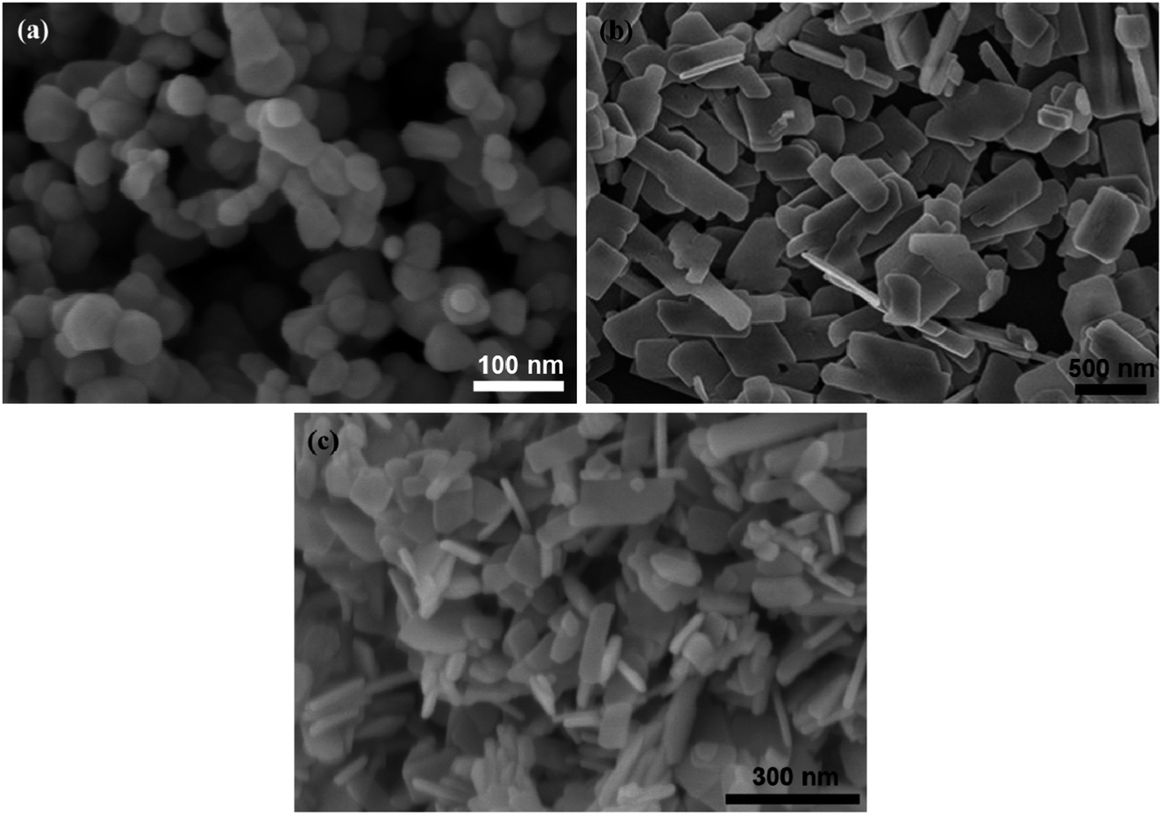 | ||
| Fig. 3 SEM images of (a) ZnO NPs, (b) CuO nanoplates, and (c) CuO/ZnO nanocomposites with a ZnO-to-CuO weight ratio of 4:6. | ||
Fig. 4 shows the EDS spectra of the CuO/ZnO sample, which substantiates the elemental composition and purity of the as-prepared composite materials. The EDS analysis exhibits that the constituents of CuO/ZnO included mainly O, Cu, and Zn. This shows that ZnO nanoparticles were successfully anchored on the CuO nanoplate surfaces. The EDX mapping images (Fig. 4b–e) further confirm that the sample was composed of O, Cu and Zn. The elemental distribution of Cu, Zn, and O atoms in the CuO/ZnO heterostructures helps us identify the region of interfacial junction between CuO and ZnO. The EDX mappings show the even distribution of Zn, Cu, and O in all the samples, which confirm the fused geometry of CuO nanoplates and ZnO nanoparticles (Fig. 4a).
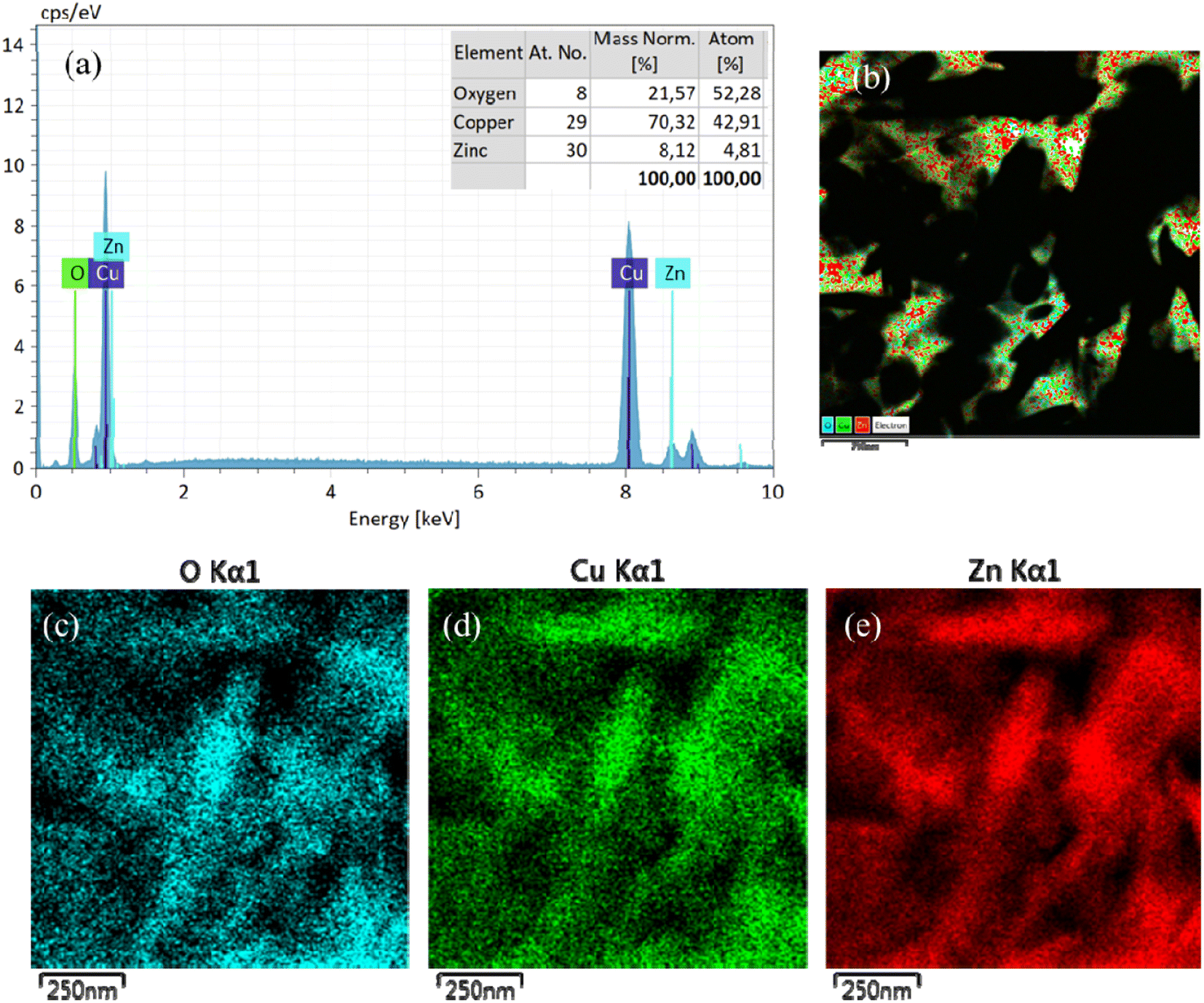 | ||
| Fig. 4 (a) EDS elemental analysis of CuO/ZnO; EDX mapping of (b) CuO/ZnO sample showing the distribution of (c) O, (d) Cu, and (e) Zn elements in the CuO/ZnO composite. | ||
The crystallinity and phase identification of the as-prepared CuO, ZnO, and CuO/ZnO hybrid specimens were characterized by a powder XRD analysis, as represented in Fig. 5a. The main diffraction peaks of CuO appearing at 2θ of 35.5°, 38.7°, 48.7°, 61.5°, 66.2°, and 68° were ascribed to the reflection from the (002), (111), (202), (113), (311), and (220) facets, respectively, which corresponds to the crystalline monoclinic CuO, which is in good correspondence with the standard value (JCPDS card number 89-5895).63 The diffraction peaks at 31.4°, 34.6°, 36.3°, 47.6°, 56.7°, 63°, and 66.5° were ascribed to the (100), (002), (101), (102), (110), (103), and (200) planes, respectively, corresponding to hexagonal wurtzite ZnO in accordance with the standard pattern (JCPDS card no. 36-1451).59 The XRD patterns of the CuO/ZnO nanocomposite sample represent all of the diffraction peaks associated with CuO. The peaks associated with ZnO do not appear separately in binary composites but appear in pure ZnO. The diminished intensity of ZnO peaks in the mixed nanocomposite gives evidence for the formation of coupled oxides.64 The crystalline nature of copper oxide remained unaltered in the CuO/ZnO heterojunction. CuO was a major phase in this two-phase mixed-metal oxide composite due to the small size of ZnO nanoparticles compared to CuO nanoplates. No additional peak is observed in the XRD patterns, which represents the highly pure phase of synthesized materials.
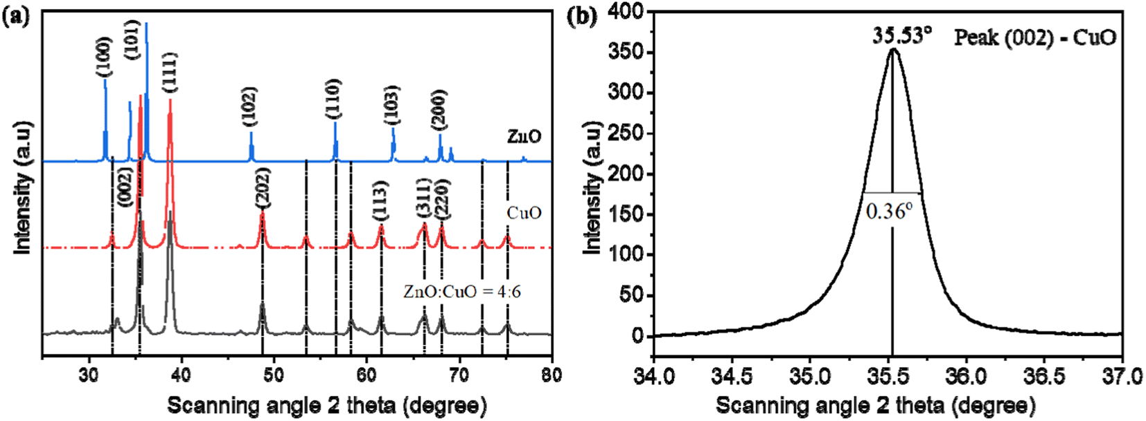 | ||
| Fig. 5 (a) XRD patterns of pristine the CuO, ZnO, and CuO/ZnO composite. (b) Full width at half maximum of peak (002) of CuO. | ||
An diffraction peak associated with ZnO or CuO in the pattern was used to determine the average crystalline size using Debye–Scherrer's equation as follows:65
 | (5) |
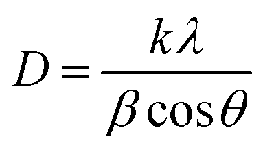
It is clear from the UV-Vis absorption spectra in Fig. 6 that ZnO is a UV-responsive material, while CuO/ZnO gave the light response in the range of visible light. We can see that the absorption edge of CuO/ZnO is slightly red-shifted compared to pure CuO and ZnO. This red-shift could be attributed to electron transfer between the valence band of CuO and the conduction band of ZnO. Thus, the composite samples can harvest the visible light region toward the generation of a large number of photogenerated charge carriers, which improves the photocatalytic performance. Since ZnO and CuO exhibit direct bandgaps, the Tauc model was used to calculate the band gap energy given in the following equation:66
| (αhν)n = A(hν − Eg) | (6) |
:6, respectively. It is clear that the bandgap energy of CuO/ZnO nanocomposites obtained from Tauc plot is smaller than those of pure CuO or ZnO.67 The red-shift in absorption wavelength is attributed to the formation of CuO/ZnO nanocomposites, and the generation of some localized energy states and oxygen vacancies in ZnO.68 Superior photocatalytic performance of CuO/ZnO nanocomposites is attributed to the existence of oxygen vacancies, which favors good adsorption capacity.69
 | ||
| Fig. 6 UV-Vis spectra and corresponding Tauc's plots (inset) of (a) CuO, (b) ZnO, and (c) ZnO:CuO = 4:6 samples. | ||
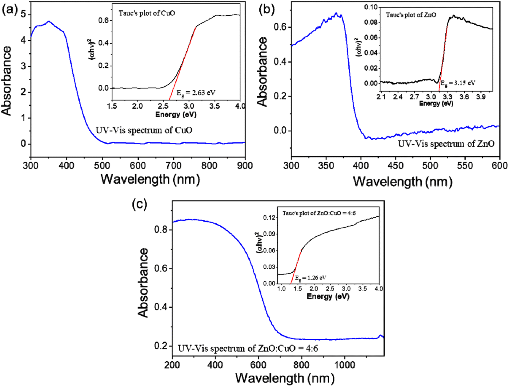
The Fourier transform infrared (FTIR) spectra within the range of 400 to 4000 cm−1 were used to determine the functional groups in the CuO/ZnO nanocomposites (Fig. 7a). The frequency at about 3460 cm−1 corresponds to the O–H stretching vibration.70 The peaks around 1636 and 1414 cm−1 indicate the C![[double bond, length as m-dash]](https://www.rsc.org/images/entities/char_e001.gif) O stretching mode and OCO bond, which are attributed to the absorption of CO2 on the surface of CuO/ZnO hybrids.71 The peak at 600 cm−1 is due to the vibration of the Cu–O bond in CuO.67 The band at 507 cm−1 is assigned to the vibration of the Zn–O bond in ZnO.72 The PL spectra of CuO, ZnO and CuO/ZnO nanocomposites are illustrated in Fig. 7b. The photoluminescence (PL) spectra of ZnO consists of two characteristic emissions: the 400 nm peak is assigned to the near band-edge (NBE) exciton emission19 and the 650 nm peak is assigned to deep level emission (DLE) from intrinsic and extrinsic defects.25 The combination of CuO with ZnO has an important impact on the optical property and efficiency of photocatalysts. A small band in the range of 470 nm results from the recombination of photoinduced electrons and holes.
O stretching mode and OCO bond, which are attributed to the absorption of CO2 on the surface of CuO/ZnO hybrids.71 The peak at 600 cm−1 is due to the vibration of the Cu–O bond in CuO.67 The band at 507 cm−1 is assigned to the vibration of the Zn–O bond in ZnO.72 The PL spectra of CuO, ZnO and CuO/ZnO nanocomposites are illustrated in Fig. 7b. The photoluminescence (PL) spectra of ZnO consists of two characteristic emissions: the 400 nm peak is assigned to the near band-edge (NBE) exciton emission19 and the 650 nm peak is assigned to deep level emission (DLE) from intrinsic and extrinsic defects.25 The combination of CuO with ZnO has an important impact on the optical property and efficiency of photocatalysts. A small band in the range of 470 nm results from the recombination of photoinduced electrons and holes.
 | ||
| Fig. 7 (a) FTIR spectra of CuO, ZnO and CuO/ZnO nanocomposites with different ZnO-to-CuO weight ratios. (b) Corresponding PL spectra recorded in the range of 300–800 nm. | ||
The visible emission intensity decreases with the increase in CuO content, indicating the decrease in the radiative recombination rate of photoinduced electron–hole pairs.73 Therefore, the photocatalytic activity would be expected to increase from ZnO:CuO = 8:2 to ZnO:CuO = 4:6. With the further increase in CuO content to ZnO:CuO = 2:8, the intensity of PL emission was enhanced. Electrons from the conduction band of CuO can flow into the conduction band of ZnO, leading to the improvement of the recombination rate of e/h pairs. Hence, the PL intensity is enhanced and the photocatalytic performance of ZnO:CuO = 2:8 decreases.
3.2. Photocatalytic MB degradation
The photocatalytic activity of the as-constructed CuO, ZnO, and CuO/ZnO composites was quantitatively estimated by measuring the decomposition of the MB aqueous solution under GLED light for different irradiation durations from 5 min to 150 min with the initial MB concentration of 5 ppm. To evaluate the effect of different ZnO-to-CuO mass ratios on the MB photodegradation capacity of the obtained photocatalysts, preliminary experiments were carried out with pristine CuO, ZnO, CuO/ZnO at different ZnO-to-CuO mass ratios of 2:8, 4:6, 5:5, 6:4, and 8:2. The decrease in MB concentration with time was estimated using a UV-Vis spectrophotometer, as shown in Fig. 8. It can be seen that the CuO/ZnO nanocomposites demonstrated better photocatalytic performance than pristine CuO and ZnO. The results indicate that ZnO:CuO = 4:6 exhibited the best performance among the as-synthesized photocatalysts. The increase in the CuO content in the CuO/ZnO composite enhanced the photocatalytic activity due to the increase in carrier trapping sites, leading to the improvement of charge separation and the extension of the carrier lifetime.
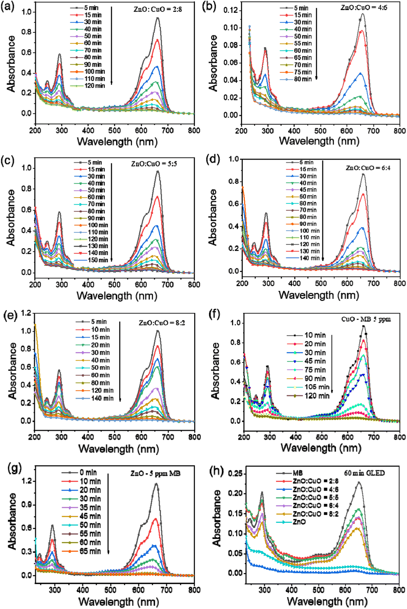 | ||
| Fig. 8 UV-Vis spectra of CuO/ZnO nanocomposites with different ZnO-to-CuO ratios: (a) 2:8, (b) 4:6, (c) 5:5, (d) 6:4, (e) 8:2, (f) pristine CuO, (g) pristine ZnO under GLED exposure, and (h) comparison of the degradation efficiency of different samples. | ||
The specific surface area commonly plays an important role in photocatalytic process. The surface area of synthesized materials depends on geometrical shape, particle size and porosity of the samples. The combination of CuO nanoplates and ZnO nanoparticles increased the surface area and created new absorption sites.74 The small ZnO nanoparticles have higher surface area than that of CuO nanoplates. An increase in the surface area of CuO/ZnO composites might be due to an increase in the porosity of the samples. The larger surface area provides more oxygen defects and more active sites for pollutant adsorption, leading to higher photocatalytic activity.75
The superior photocatalytic competency of the ZnO:CuO = 4:6 sample was confirmed via their comparison with the results of other ZnO-to-CuO ratios and the information is presented in Fig. 9. However, with the further decrease in ZnO content to ZnO:CuO = 2:8, the photocatalytic performance decreases due to an insufficient amount of ZnO to provide effective separation to charge carriers. After attaining an optimum ratio, i.e., ZnO:CuO = 4:6, the ZnO nanoparticles start agglomerating (i.e., ZnO:CuO = 5:5, 6:4, and 8:2), which results in the reduction in surface area as well as photocatalytic activity. Moreover, the large amount of ZnO nanoparticles covering the surface of CuO form a cluster and reduce the active sites available for the photocatalysis, which is in compliance with the previously reported work.16 The reduced surface oxygen vacancies acting as electron donors in ZnO provide additional electrons to the CB of ZnO.76 The most prominent reason behind the enhanced efficacy of binary nanocomposites was ascribed to charge separation due to the formation of heterojunctions in hybrid systems. The weakest degradation of MB was recorded in the blank test, which is experiment in the absence of catalysts and without light. A little degradation of MB was achieved that agrees with the theory of self-degradation of organic pollutants. By contrast, the best photodegradation of MB was obtained for the ZnO:CuO = 4:6 sample, which is ascribed to the highest adsorption of MB molecules onto the composite surfaces, and the genesis of ·OH radicals promotes the photocatalytic reaction. Fig. 9a reveals the quantitative degradation efficacy of MB as a function of irradiation time using CuO/ZnO photocatalysts having different ZnO-to-CuO ratios. The photodecomposition percentage of MB was calculated using the following equation:4
 | (7) |
:CuO = 2:8, 4:6 and 5:5 samples are 85.7%, 93.0%, and 83.1%, respectively.
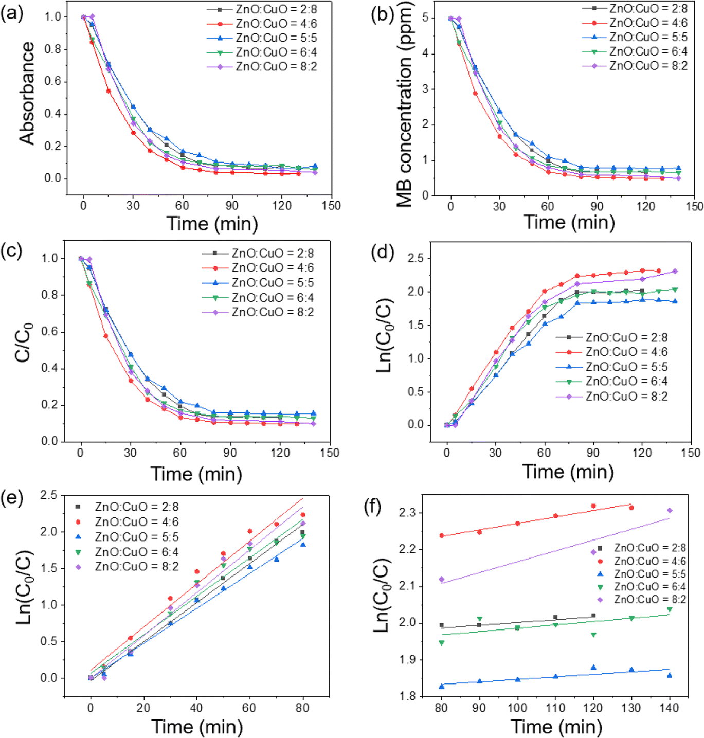 | ||
| Fig. 9 (a) Absorbance of the MB solution at different time intervals, (b) dependence of MB concentration on the GLED illumination time, (c) time-dependent, normalized concentration of methylene blue under visible light irradiation for CuO/ZnO nanocomposites, (d) ln(Co/C) curve as a function of irradiation time, and reaction kinetic plots (e) in the range of 0–80 min and (f) from 80 to 140 min irradiation. | ||
The maximum efficiency in degrading MB was achieved for the ZnO:CuO = 4:6 sample. In this experimental scenario, the photocatalytic process slowed down after 60 min and the MB concentration became stable after 150 min (Fig. 9f). In the initial stage, the CuO/ZnO surface had a large number of fresh adsorption active sites leading to a rapid reaction. After 60 min, the adsorption process became slower and approached stability because of the saturation of available active sites on the surface of catalysts and the reduction in the concentration of MB in the solution. This trend was similar to the phosphate adsorption from aqueous solutions.74
Fig. 9b describes the decrease in MB concentration after GLED irradiation. It is clear that CuO/ZnO nanocomposites possess much better photocatalytic activity than that of pure ZnO or CuO. Especially, CuO/ZnO with ZnO:CuO = 4:6 has the best photocatalytic activity, showing the decrease in MB concentration from the initial value of 5 ppm to 0.67 ppm within only 60 min. While for pristine ZnO or CuO under GLED irradiation with 60 min or 90 min, respectively, only 70% MB can be degraded.
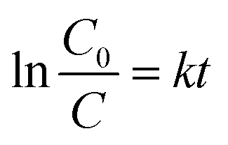
The quantitative degradation efficacy of MB was evaluated via the evolution of C/C0 as a function of time (Fig. 9c), where C0 is the initial concentration of the MB aqueous solution and C is the MB concentration at time t. To measure the rate constant and degradation kinetics, the plot of ln(C0/Ct) with GLED illuminating time, as displayed in Fig. 9e, revealed the pseudo-first-order reaction kinetic model as follows:39
 | (8) |
:CuO = 4:6 has the highest photocatalytic activity with a rate constant (k) of 0.0295 min−1 and ZnO:CuO = 5:5 has the lower photocatalytic activity with a rate constant of 0.0212 min−1. The values of k for pristine ZnO and pristine CuO were estimated to be 0.0154 and 0.0254 min−1, respectively. It was pointed out from rate constant values that ZnO:CuO = 4:6 nanocomposite possesses the highest photocatalytic activity compared with other samples. The value of k for the sample with ZnO:CuO = 4:6 was estimated to be 1.8 times the magnitude larger than that of ZnO. Thus, the photocatalytic activity of the composite is improved compared to that of pristine ZnO or CuO. The decline in photocatalytic capacity at a higher ZnO-to-CuO ratio might be due to the aggregation of ZnO nanoparticles, which reduced the effective surface area and active sites for MB adsorption. This result agrees with the above-mentioned PL spectra and other studies, which indicated that the ZnO-to-CuO ratio plays an important role in the photocatalytic process.63,77 Table 1 compares the photocatalytic efficacy of some previously reported CuO/ZnO systems.
| Method | Morphology | Organic pollutant | Rate constant (min−1) | Reference |
|---|---|---|---|---|
| Hydrothermal | Flake/bittergourd | Triclopyr | — | 47 |
| Co-crystallization | Nanoparticles/nanobullets | Methylene blue | 0.0529 | 11 |
| Thermal transformation | Plate | Ciprofloxacin | 0.009 | 39 |
| Electrodeposition | Nanoparticles | Brilliant blue | 0.029 | 35 |
| Hydrothermal | Nanoparticles/nanowires | Methylene blue | 0.03543 | 41 |
| Hydrothermal | Nanoplates/nanoparticles | Methylene blue | 0.0295 | This work |
3.3. Mechanism of photocatalytic activity
ZnO possesses a wide direct bandgap of approximately 3.37 eV with an exciton binding energy of 60 meV, allowing ultraviolet (UV) adsorption at room temperature.60 When the ZnO photocatalyst is illuminated with a photonic energy greater than the bandgap (Eg), the electrons from the valence band (VB) are promoted to the conduction band (CB) to generate electron–hole (e/h) pairs. However, owing to the wide bandgap of ZnO, only ultraviolet (UV) is available to excite electrons from the valence band (VB) to the conduction band (CB), which limits the practical use of ZnO. Combining CuO with ZnO can extend the light absorption to the visible region, increase carrier mobility, and reduce electron–hole pairs recombination.77 In addition, the lifetime of the photocatalyst can be shortened owing to photocatalyst leaching and dissolution during irradiation, which introduce Zn pollutants into treated water.78 Many authors have minimized the recombination loss of charge carriers via deposition of ZnO with noble metals (Pt, Pd, Au, and Ag) and extended the light response to visible light by coupling with other metal oxides (TiO2, SnO2, Fe2O3, and CuO), thus improved the light trapping ability, capacity to adsorb pollutants and global photocatalytic performance.25,62,79,80The photocatalytic mechanism of the CuO/ZnO hybrid under visible light irradiation can be explained in terms of greater separation of the photo-induced electrons and holes via the p–n heterojunction between ZnO and CuO. The p–n junction forms a junction potential at the interface between ZnO and CuO. The inner electric field causes the charge polarity, where the n-type ZnO is positively charged and the p-type CuO is negatively charged.81 It is plausible for CuO nanoplates to support electron–hole pair generation, while ZnO nanoparticles act as the carrier pathway. When irradiated with GLED, electrons in the valence band (VB) of CuO were excited to the conduction band (CB). From the thermodynamic point of view, the photogenerated electrons immigrate from CuO to ZnO and are trapped by the heterojunction. In the meantime, the holes transfer in the opposite direction from the VB of ZnO to that of CuO, as depicted in Fig. 10. Consequently, the photoinduced e/h pairs could be effectively separated, leading to a larger number of electrons and holes participating in catalytic reactions. The formation of CuO/ZnO heterostructures created defects, narrowed the energy bandgap, and shifted the electronic energy band structure of ZnO, which controlled the charge recombination process and helped to absorb visible light.82
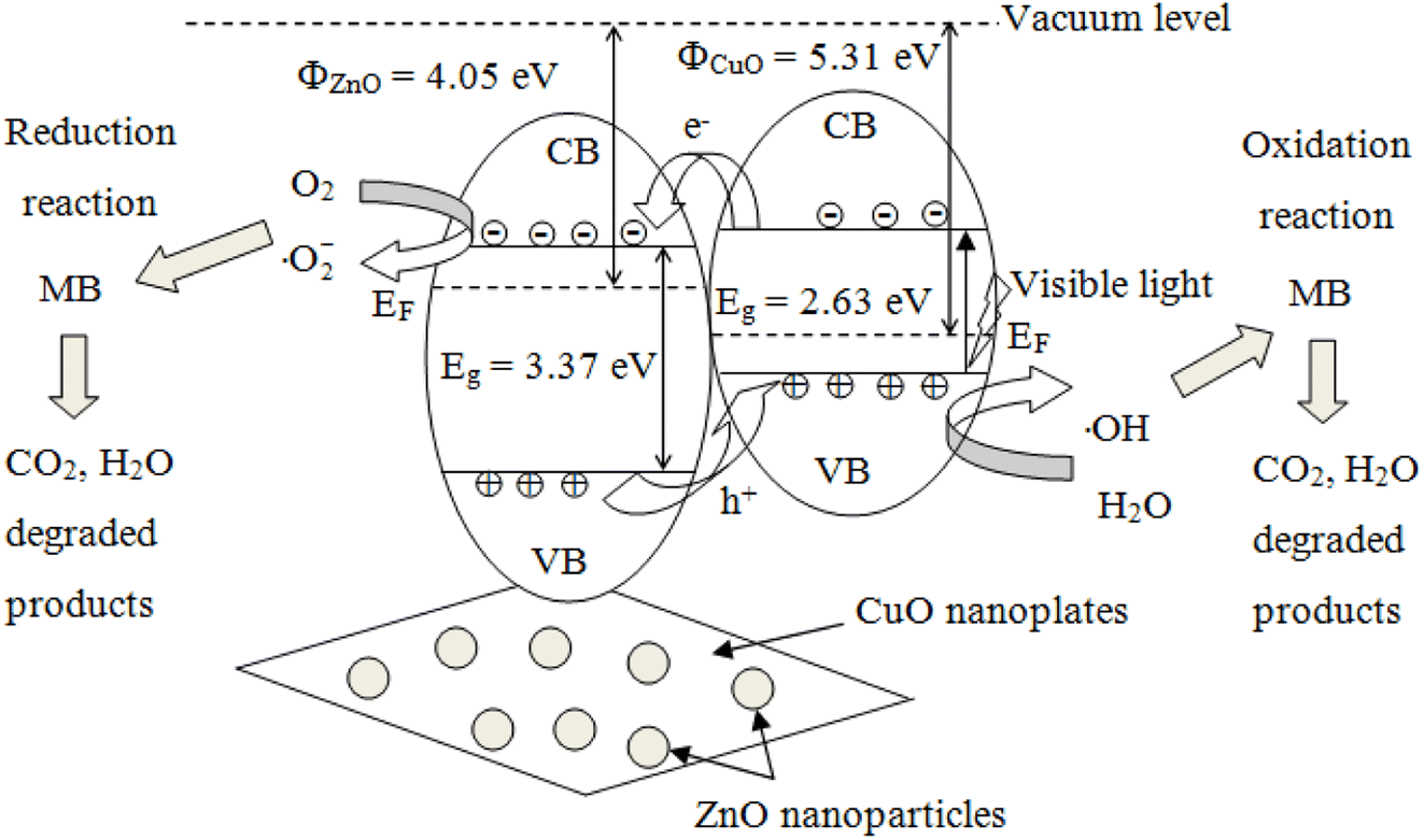 | ||
| Fig. 10 Illustration of the photodegradation of MB using CuO/ZnO catalysts. | ||
Fig. 10 illustrates the energy–level diagram of ZnO nanoparticle-decorated CuO nanoplates and the pathway for the transfer of charge carriers. The conduction and valence bands of ZnO lie lower than those of CuO, as mentioned in a previously reported article.47 When CuO is illuminated with visible light, the photogenerated electrons of the VB of CuO become excited to the CB and leave holes in the VB:21
| Photon (hν) + CuO → h+ (VB) + e− (CB) | (9) |
Photogenerated electrons move from the CB of CuO to the CB of ZnO, while photogenerated holes move from the VB of ZnO to the VB of CuO. Therefore, the CuO/ZnO heterojunction efficiently enhances the charge separation and increases the recombination time for the e/h pairs.
The oxidative species generated from the photoinduced charge carriers (electrons and holes) contain superoxide anion radicals (·O2−) and hydroxyl radicals (·OH). Electrons were captured by dissolved oxygen molecules in water or adsorbed O2 species to produce highly active anion radicals as follows:
| e− + O2 → ·O2− | (10) |
The superoxide anions react with H+ ions to produce hydrogen peroxide molecules as follows:
| ·O2− + 2H+ → H2O2 | (11) |
The hydrogen peroxide molecules react with photogenerated electrons to form highly reactive hydroxyl radicals as follows:
| e− + H2O2 → ·OH + OH− | (12) |
Hydrogen peroxide (H2O2) can react with superoxide radicals to form hydroxyl radicals as follows:
| H2O2 + ·O2− → ·OH + OH− + O2 | (13) |
| h+ + H2O → H+ + ·OH | (14) |
| h+ + OH− → ·OH | (15) |
Both radicals are called reactive oxidation species (ROS), which are powerful oxidizing agents for organic molecule treatment. These oxidant radicals are responsible for the complete mineralization of pollutants.83 The ROS rapidly react with the organic pollutants adsorbed on the ZnO surface to generate nontoxic chemicals, containing carbon dioxide, water, and inorganic compounds.62 Methylene blue (MB) molecules anchored onto the active surface of the photocatalyst are decomposed by these radicals in an oxidation process:61
| MB + ·OH → CO2 + H2O + other products | (16) |
| MB + ·O2− → CO2 + H2O + other products | (17) |
MB molecules are transformed into less toxic inorganic molecules such as CO2, H2O, SO42−, NO3−, and Cl−. The intermediates or byproducts of MB decomposition are small fragments leading to mineralization. Amidst oxidation, ·OH radicals exfoliate the benzene rings of MB molecules until the innocuous inorganic end products get formed.57 The degradation end products may contain organic acids such as oxalic acid and acetic acid.84
A great number of photocatalytical active sites will create a great proportion of ·OH and ·O2− radicals, which is essential for photodegradation reactions. CuO has a smaller bandgap than ZnO and can absorb a greater amount of light energy than ZnO, but the instant recombination of electrons and holes of CuO is faster than that of ZnO. When a CuO/ZnO heterojunction is illuminated, the photogenerated electrons in the conduction band (CB) of CuO migrated to the CB of ZnO.85 The holes generated in the valence band (VB) of ZnO get further excited to the CuO VB, resulting from heterojunction formation that leads to efficient charge separation. Superoxide (·O2−) radicals are generated in the CB of the ZnO section, while hydroxyl (·OH) radicals are formed in the CuO VB.
The improved photocatalytic activity of CuO/ZnO nanocomposites could be attributed to the low recombination rate of photoinduced charge carriers and the more favorable charge transfer through CuO/ZnO heterostructures. The formation of CuO/ZnO heterostructures resulted in a highly accessible surface, which offers lots of active sites for pollutant adsorption and high charge separation efficiency of e/h pairs, and prolongs the lifetime of charge carriers. Consequently, CuO/ZnO nanocomposites offer high photogeneration of ROS under visible light.20 However, the enhanced photocatalytic performance under visible light remains controversial, thus more investigations are required to clarify and understand the MB photodegradation mechanism using CuO/ZnO nanocomposites.
4. Conclusions
In summary, we have successfully prepared a series of p–n CuO/ZnO heterojunction nanocomposites by a hydrothermal method and precipitation followed by mechanical blending. The as-prepared nanocomposites were characterized by standard techniques such as SEM, XRD, EDS, UV-Vis spectroscopy, FTIR spectroscopy, and PL spectroscopy. The UV-Vis results revealed that CuO/ZnO hybrids had the lower energy band gap than those of pristine CuO or ZnO. The proficiency of the as-synthesized nanocomposites in the photodecomposition of MB was evaluated under GLED irradiation. Among the CuO/ZnO nanocomposites, ZnO:CuO = 4:6 revealed the highest activity for MB degradation with 93% photodeterioration within 60 min of exposure to GLED light. The rate constant (k) for the sample with ZnO:CuO = 4:6 was 0.0295 min−1 for the initial 60 min GLED irradiation. The excellent photocatalytic MB dye decomposition ability of CuO/ZnO nanocomposites is expected to render a critical role in environmental detoxification.
This study has shown that the formation of CuO/ZnO heterostructures can improve the photocatalytic activity by increasing light absorption, charge separation and transportation, prolonging the lifetime of charge carriers, and improving pollutant-adsorbing capability. The CuO/ZnO heterojunction could reduce the photoinduced e/h recombination to generate effective oxidants. This finding provides a potential photocatalyst based on CuO/ZnO composites for organic pollutant remediation, especially methylene blue.
Author contributions
Nguyen Dac Dien: investigation, methodology, writing – original draft, writing – review & editing. Pham Thi Thu Ha: experiment, formal analysis, visualization. Xuan Hoa Vu: funding acquisition, project administration, conceptualization, data curation, supervision. Tran Thu Trang: investigation, methodology, writing – review & editing. Trinh Duc Thanh Giang: experiment. Nguyen Thi Dung: formal analysis, validation, resources, software. All authors provided critical feedback and helped shape the research, analysis and manuscript.Conflicts of interest
There are no conflicts of interest to declare.Acknowledgements
This research was funded by Vietnam Trade Union University under grant number 1461/QD-DHCD in 2022 and Project of the TNU-University of Sciences in Vietnam under grant no. CS2023-TN06-14.References
- C. do Nascimento Brito, D. R. Da Silva, S. Garcia-Segura, D. C. De Moura and C. A. Martínez-Huitle, J. Electrochem. Soc., 2015, 163, 62–69 CrossRef.
- C. Lops, A. Ancona, K. Di Cesare, B. Dumontel, N. Garino, G. Canavese, S. Hérnandez and V. Cauda, Appl. Catal., B, 2019, 243, 629–640 CrossRef CAS PubMed.
- J. Di, M. Zhu, R. Jamakanga, X. Gai, Y. Li and R. Yang, J. Water Process. Eng., 2020, 37, 101386 CrossRef.
- S. Harish, J. Archana, M. Sabarinathan, M. Navaneethan, K. D. Nisha, S. Ponnusamy, C. Muthamizhchelvan, H. Ikeda, D. K. Aswal and Y. Hayakawa, Appl. Surf. Sci., 2017, 418, 103–112 CrossRef CAS.
- P. Bharathi, S. Harish, J. Archana, M. Navaneethan, S. Ponnusamy, C. Muthamizhchelvan, M. Shimomura and Y. Hayakawa, Appl. Surf. Sci., 2019, 484, 884–891 CrossRef CAS.
- R. D. C. Soltani, S. Jorfi, M. Safari and M.-S. Rajaei, J. Environ. Manage., 2016, 179, 47–57 CrossRef.
- F. Cao, T. Wang and X. Ji, Appl. Surf. Sci., 2019, 471, 417–424 CrossRef CAS.
- K. Micheal, A. Ayeshamariam, R. Boddula, P. Arunachalam, M. S. AlSalhi, J. Theerthagiri, S. Prasad, J. Madhavan and A. M. Al-Mayouf, Mater. Sci. Energy Technol., 2019, 2, 104–111 Search PubMed.
- P. Raizada, A. Sudhaik, P. Singh, P. Shandilya, P. Thakur and H. Jung, Arabian J. Chem., 2020, 13, 3196–3209 CrossRef CAS.
- P. Raizada, A. Sudhaik, P. Singh, P. Shandilya, A. K. Saini, V. K. Gupta, J.-H. Lim, H. Jung and A. Hosseini-Bandegharaei, Sep. Purif. Technol., 2019, 212, 887–900 CrossRef CAS.
- K. P. Sapkota, I. Lee, S. Shrestha, A. Islam, A. Hanif, J. Akter and J. R. Hahn, J. Environ. Chem. Eng., 2021, 9, 106497 CrossRef CAS.
- M. K. Hussain, N. Khalid, M. Tahir, M. Tanveer, T. Iqbal and M. Liaqat, Mater. Sci. Semicond. Process., 2023, 155, 107261 CrossRef CAS.
- D. K. L. Harijan, S. Gupta, S. K. Ben, A. Srivastava, J. Singh and V. Chandra, Phys. B, 2022, 627, 413567 CrossRef CAS.
- P. V. Tuan, H. B. Tuong, V. T. Tan, L. H. Thu, N. D. Khoang and T. N. Khiem, Opt. Mater., 2022, 123, 111916 CrossRef.
- C. Zhang, N. Li, D. Chen, Q. Xu, H. Li, J. He and J. Lu, J. Alloys Compd., 2021, 885, 160987 CrossRef CAS.
- V. Kumari, S. Yadav, A. Mittal, S. Sharma, K. Kumari and N. Kumar, J. Mater. Sci.: Mater. Electron., 2020, 31, 5227–5240 CrossRef CAS.
- S. Sharma, N. Kumar, B. Mari, N. S. Chauhan, A. Mittal, S. Maken and K. Kumari, Inorg. Chem. Commun., 2021, 125, 108418 CrossRef CAS.
- K. M. Lee, C. W. Lai, K. S. Ngai and J. C. Juan, Water Res., 2016, 88, 428–448 CrossRef CAS PubMed.
- J. Zhang, T. Chen, J. Yu, C. Liu, Z. Yang, H. Lu, F. Yin, J. Gao, Q. Liu and X. Zhang, J. Mater. Sci.: Mater. Electron., 2016, 27, 10667–10672 CrossRef CAS.
- M. Nami, A. Rakhsha, S. Sheibani and H. Abdizadeh, Mater. Sci. Eng., B, 2021, 271, 115262 CrossRef CAS.
- A. A. Yaqoob, N. H. b. M. Noor, A. Serrà and M. N. M. Ibrahim, Nanomater, 2020, 10, 932 CrossRef CAS.
- A. Serrà, Y. Zhang, B. Sepúlveda, E. Gómez, J. Nogués, J. Michler and L. Philippe, Appl. Catal., B, 2019, 248, 129–146 CrossRef.
- S. Yadav, J. Jindal, A. Mittal, S. Sharma, K. Kumari and N. Kumar, J. Phys. Chem. Solids, 2021, 157, 110217 CrossRef CAS.
- S. P. Mardikar, S. Kulkarni and P. V. Adhyapak, J. Environ. Chem. Eng., 2020, 8, 102788 CrossRef CAS.
- V. D. Thinh, V. D. Lam, T. N. Bach, N. D. Van, D. H. Manh, D. H. Tung, N. T. H. Lien, U. T. D. Thuy, T. X. Anh, N. T. Tung and N. T. H. Le, J. Electron. Mater., 2020, 49, 2625–2632 CrossRef CAS.
- S. Shekoohiyan, A. Rahmania, M. Chamack, G. Moussavi, O. Rahmanian, V. Alipour and S. Giannakis, Sep. Purif. Technol., 2020, 242, 116821 CrossRef CAS.
- A. Roy and M. Benhaliliba, Opt, 2023, 274, 170557 CAS.
- D. D. Nguyen, D. T. Do, X. H. Vu, D. V. Dang and D. C. Nguyen, Adv. Nat. Sci.: Nanosci. Nanotechnol., 2016, 7, 015004 Search PubMed.
- V. Gerbreders, M. Krasovska, I. Mihailova, A. Ogurcovs, E. Sledevskis, A. Gerbreders, E. Tamanis, I. Kokina and I. Plaksenkova, Sens. Bio-Sens. Res., 2019, 23, 100276 CrossRef.
- T. Kavitha, A. I. Gopalan, K.-P. Lee and S.-Y. Park, Carbon, 2012, 50, 2994–3000 CrossRef CAS.
- Y. Zhang, Y. Yan, L. Yang, C. Xing, Y. Zeng, Y. Zhao and Y. Jiang, Opt. Express, 2019, 27, 15399–15412 CrossRef CAS PubMed.
- S. T. Fardood, A. Ramazani, S. Moradi and P. A. Asiabi, J. Mater. Sci.: Mater. Electron., 2017, 28, 13596–13601 CrossRef.
- R. Mohammed, M. E. M. Ali, E. Gomaa and M. Mohsen, J. Environ. Chem. Eng., 2020, 8, 104295 CrossRef CAS.
- I. J. Ani, U. G. Akpan, M. A. Olutoye and B. H. Hameed, J. Cleaner Prod., 2018, 205, 930–954 CrossRef CAS.
- R. Youcef, A. Benhadji, D. Zerrouki, N. Fakhakh, H. Djelal and M. T. Ahmed, React. Kinet., Mech. Catal., 2021, 133, 541–561 CrossRef CAS.
- J. Singh and R. K. Soni, Appl. Surf. Sci., 2020, 521, 146420 CrossRef CAS.
- A. Molkenova, S. Sarsenov, S. Atabaev, L. Khamkhash and T. S. Atabaev, Environ. Nanotechnol., Monit. Manage., 2021, 16, 100507 CAS.
- C. Liu, F. Meng, L. Zhang, D. Zhang, S. Wei, K. Qi, J. Fan, H. Zhang and X. Cui, Appl. Surf. Sci., 2019, 469, 276–282 CrossRef CAS.
- J. Trakulmututa, C. Chuaicham, S. Shenoy, A. Srikhaow, K. Sasaki and S. M. Smith, Opt. Mater., 2022, 133, 112941 CrossRef CAS.
- L. Xu, J. Su, G. Zheng and L. Zhang, Mater. Sci. Eng., B, 2019, 248, 114405 CrossRef CAS.
- Y. Lv, J. Liu, Z. Zhang, W. Zhang, A. Wang, F. Tian, W. Zhao and J. Yan, Mater. Chem. Phys., 2021, 267, 124703 CrossRef CAS.
- L. Xu, Y. Zhou, Z. Wu, G. Zheng, J. He and Y. Zhou, J. Phys. Chem. Solids, 2017, 106, 29–36 CrossRef CAS.
- M. Hassanpour, H. Safardoust-Hojaghan, M. Salavati-Niasari and A. Yeganeh-Faal, J. Mater. Sci.: Mater. Electron., 2017, 28, 14678–14684 CrossRef CAS.
- M. Nami, S. Sheibani and F. Rashchi, Mater. Sci. Semicond. Process., 2021, 135, 106083 CrossRef CAS.
- K. Salehi, A. Bahmani, B. Shahmoradi, M. A. Pordel, S. Kohzadi, Y. Gong, H. Guo, H. P. Shivaraju, R. Rezaee and R. R. Pawar, Int. J. Environ. Sci. Technol., 2017, 14, 2067–2076 CrossRef CAS.
- C. Chen, X. Liu, Q. Fang, X. Chen, T. Liu and M. Zhang, Vac, 2020, 174, 109198 CrossRef CAS.
- V. Kumari, S. Sharma, A. Sharma, K. Kumari and N. Kumar, J. Mater. Sci.: Mater. Electron., 2021, 32, 9596–9610 CrossRef CAS.
- M. S. AlSalhi, A. Sakthisabarimoorthi, S. Devanesan, S. A. Martin Britto Dhas and M. Jose, J. Mater. Sci.: Mater. Electron., 2019, 30, 13708–13718 CrossRef CAS.
- K. Pouthika and G. Madhumitha, Inorg. Chim. Acta, 2023, 121457 CrossRef CAS.
- T. Tangcharoen, W. Klysubun and C. Kongmark, J. Mater. Sci.: Mater. Electron., 2020, 31, 12807–12822 CrossRef CAS.
- A. Desore and S. A. Narula, Environ. Dev. Sustain., 2018, 20, 1439–1459 CrossRef.
- A. Hassani, P. Eghbali and Ö. Metin, Environ. Sci. Pollut. Res., 2018, 25, 32140–32155 CrossRef CAS PubMed.
- M. Moztahida and D. S. Lee, J. Hazard. Mater., 2020, 400, 123314 CrossRef CAS PubMed.
- M. Xu, X. Bai, L. Pei and H. Pan, Int. J. Hydrogen Energy, 2016, 41, 15930–15937 CrossRef CAS.
- H. T. Van, T. M. P. Nguyen, V. T. Thao, X. H. Vu, T. V. Nguyen and L. H. Nguyen, Water, Air, Soil Pollut., 2018, 229, 393 CrossRef.
- M. Manasa, P. R. Chandewar and H. Mahalingam, Catal. Today, 2021, 375, 522–536 CrossRef CAS.
- Y. Liu, W. Jin, Y. Zhao, G. Zhang and W. Zhang, Appl. Catal., B, 2017, 206, 642–652 CrossRef CAS.
- H. Ullah, M. B. Vishlaghi, T. Balkan, Z. U. Rehman and S. Kaya, Inorg. Chem. Commun., 2021, 130, 108744 CrossRef CAS.
- K. P. Sapkota, I. Lee, M. A. Hanif, M. A. Islam and J. R. Hahn, Catal, 2019, 9, 498 CrossRef.
- T. W. Gebreslassie, M. Pattabi and R. M. Pattabi, Int. J. Hydrogen Energy, 2015, 4, 2252–2264 Search PubMed.
- T. T. Minh, N. T. T. Tu, T. T. V. Thi, L. T. Hoa, H. T. Long, N. H. Phong, T. L. M. Pham and D. Q. Khieu, J. Nanomater., 2019, 2019, 5198045 Search PubMed.
- K. Sahu, A. Bisht, S. Kuriakose and S. Mohapatra, J. Phys. Chem. Solids, 2020, 137, 109223 CrossRef CAS.
- X. He, D.-P. Yang, X. Zhang, M. Liu, Z. Kang, C. Lin, N. Jia and R. Luque, Chem. Eng. J., 2019, 369, 621–633 CrossRef CAS.
- A. Hezam, K. Namratha, Q. A. Drmosh, Z. H. Yamani and K. J. C. I. Byrappa, Ceram. Int., 2017, 43, 5292–5301 CrossRef CAS.
- C. P. Goyal, D. Goyal, K. Rajan, N. S. Ramgir, Y. Shimura, M. Navaneethan, Y. Hayakawa, C. Muthamizhchelvan, H. Ikeda and S. Ponnusamy, Cryst, 2020, 10, 188 CrossRef CAS.
- P. Makuła, M. Pacia and W. Macyk, J. Phys. Chem. Lett., 2018, 9, 6814–6817 CrossRef PubMed.
- Y. Shavisi, S. Sharifnia and Z. Mohamadi, J. Environ. Chem. Eng., 2016, 4, 2736–2744 CrossRef CAS.
- L. Wang, F. Meng, K. Li and F. Lu, Appl. Surf. Sci., 2013, 286, 269–274 CrossRef CAS.
- S. Hussain, N. Aslam, X.-Y. Yang, M. S. Javed, Z. Xu, M. Wang, G. Liu and G. Qiao, Ceram. Int., 2018, 44, 19624–19630 CrossRef CAS.
- S. B. Ameur, H. BelHadjltaief, B. Duponchel, G. Leroy, M. Amlouk, H. Guermazi and S. Guermazi, Heliyon, 2019, 5, 01912 Search PubMed.
- N. Tu, K. T. Nguyen, D. Q. Trung, N. T. Tuan, V. N. Do and P. T. Huy, J. Lumin., 2016, 174, 6–10 CrossRef CAS.
- V. D. Mote, Y. Purushotham and B. N. Dole, Mater. Des., 2016, 96, 99–105 CrossRef CAS.
- Y. Liang, N. Guo, L. Li, R. Li, G. Ji and S. Gan, RSC Adv., 2015, 5, 59887–59894 RSC.
- V. T. Trinh, T. M. P. Nguyen, H. T. Van, L. P. Hoang, T. V. Nguyen, L. T. Ha, X. H. Vu, T. T. Pham, T. N. Nguyen, N. V. Quang and X. C. Nguyen, Sci. Rep., 2020, 10, 3634 CrossRef CAS PubMed.
- A. Mittal, S. Sharma, T. Kumar, N. S. Chauhan, K. Kumari, S. Maken and N. Kumar, J. Mater. Sci.: Mater. Electron., 2020, 31, 2010–2021 CrossRef CAS.
- H. B. Lu, H. Li, L. Liao, Y. Tian, M. Shuai, J. C. Li, M. F. Hu, Q. Fu and B. P. Zhu, Nanotechnol, 2008, 19, 045605 CrossRef CAS PubMed.
- H. J. Biswal, P. R. Vundavilli, K. Mondal, N. P. Shetti and A. Gupta, Mater. Sci. Energy Technol., 2023, 6, 237–251 CAS.
- A. Serrà, Y. Zhang, B. Sepúlveda, E. Gomez, J. Nogués, J. Michler and L. Philippe, Water Res., 2020, 169, 115210 CrossRef PubMed.
- X. H. Vu, L. H. Phuoc, N. D. Dien, T. T. H. Pham and L. D. Thanh, J. Electron. Mater., 2019, 48, 2978–2985 CrossRef CAS.
- K. Umar, A. Aris, H. Ahmad, T. Parveen, J. Jaafar, Z. A. Majid, A. V. B. Reddy and J. Talib, J. Anal. Sci. Technol., 2016, 7, 29 CrossRef.
- S. Das and V. C. Srivastava, Mater. Sci. Semicond. Process., 2017, 57, 173–177 CrossRef CAS.
- N. Kumaresan, M. M. A. Sinthiya, K. Ramamurthi, R. R. Babu and K. Sethuraman, Arabian J. Chem., 2020, 13, 3910–3928 CrossRef CAS.
- V. Kumari, N. Kumar, S. Yadav, A. Mittal and S. Sharma, Mater. Today: Proc., 2019, 19, 650–657 CrossRef CAS.
- K. P. Sapkota, M. A. Islam, M. A. Hanif, J. Akter, I. Lee and J. R. Hahn, Nanomater, 2021, 11, 696 CrossRef CAS PubMed.
- M. Haddad, A. Belhadi and M. Trari, Advances in Renewable Hydrogen and Other Sustainable Energy Carriers, 2021, pp. 429–450 Search PubMed.
| This journal is © The Royal Society of Chemistry 2023 |