
 Open Access Article
 This Open Access Article is licensed under a Creative Commons Attribution-Non Commercial 3.0 Unported Licence
A novel label-free electrochemical immunosensor for the detection of heat shock protein 70 of lung adenocarcinoma cell line following paclitaxel treatment using L-cysteine-functionalized Au@MnO2/MoO3 nanocomposites
Yi-An Chen†
a,
Ming-You Shie† abc,
Chia-Che Hod,
Sheng-Wen Yeb,
I.-Wen Peter Chene,
Yu-Yin Shiha,
Yu-Fang Shend and
Yi-Wen Chen*abdf
abc,
Chia-Che Hod,
Sheng-Wen Yeb,
I.-Wen Peter Chene,
Yu-Yin Shiha,
Yu-Fang Shend and
Yi-Wen Chen*abdf
ax-Dimension Center for Medical Research and Translation, China Medical University Hospital, Taichung City 404332, Taiwan
bThe Master Program for Biomedical Engineering, China Medical University, Taichung City 406040, Taiwan
cDepartment of Biomedical Engineering, China Medical University, Taichung City, 40447, Taiwan
dDepartment of Bioinformatics and Medical Engineering, Asia University, Taichung City 41354, Taiwan
eDepartment of Chemistry, National Cheng Kung University, Tainan 70101, Taiwan
fGraduate Institute of Biomedical Sciences, China Medical University, Taichung City 40447, Taiwan
First published on 12th October 2023
Abstract
The future trend in achieving precision medicine involves the development of non-invasive cancer biomarker sensors that offer high accuracy, low cost, and time-saving benefits for risk clarification, early detection, disease detection, and therapeutic monitoring. A facile approach for the synthesis of MoO3 nanosheets was developed by thermally oxidizing MoS2 nanosheets in air followed by thermal annealing. Subsequently, Au@MnO2 nanocomposites were prepared using a combined hydrothermal process and in situ chemical synthesis. In this study, we present a novel immunosensor design strategy involving the immobilization of antiHSP70 antibodies on Au@MnO2/MoO3 nanocomposites modified on a screen-printed electrode (SPE) using EDC/NHS chemistry. This study establishes HSP70 as a potential biomarker for monitoring therapeutic response during anticancer therapy. Impedance measurements of HSP70 on the Au@MnO2/MoO3/SPE immunosensor using EIS showed an increase in impedance with an increase in HSP70 concentration. The electrochemical immunosensor demonstrated a good linear response in the range of 0.001 to 1000 ng mL−1 with a detection limit of 0.17 pg mL−1 under optimal conditions. Moreover, the immunosensor was effective in detecting HSP70 at low concentrations in a lung adenocarcinoma cell line following Paclitaxel treatment, indicating its potential for early detection of the HSP70 biomarker in organ-on-a-chip and clinical applications.
1. Introduction
Cancer is a leading global health issue with increasing incidence and mortality every year, impacting all communities worldwide regardless of religion, race, or age.1,2 Effective diagnosis and therapeutic strategies are critical to cancer progress management and mortality reduction. Pathological diagnosis and medical imaging technologies, including magnetic resonance imaging (MRI), X-ray, nuclear scan, computerized tomography (CT) scan, endoscopy, sonography, thermography, and positron emission tomography (PET) scan, have been used to diagnose cancers.2,3 However, drawbacks of high cost, complicated, time-consuming, and invasive diagnosis limit their potential for point-of-care testing (POCT).2–4 In order to achieve precision medicine, a non-invasive detection with high accuracy, low cost, and time-saving is required. Cancer biomarkers, including DNA, microRNA, protein, or antigen, currently are expected to play a key role in clarifying cancer status for patients, such as the risk of diseases, early detection, disease detection, and therapeutic drug monitoring.2,3,5Due to the high specificity and affinity of the protein biomarker, a critical receptor protein selection is essential to cancer treatment strategy and disease progress management. Fundamentally, circulating tumor markers and tumor tissue markers have been adapted to estimate tumor prognosis, determine the stage of cancer, detect cancer that remains after treatment (residual disease) or that has returned after treatment, and assess drug efficacy. One of the crucial cancer biomarkers, heat shock proteins (HSPs) are known to be associated with a wide variety of human cancers, including lung cancer,6–8 furthermore linked with tumor survival, metastasis, and anticancer drug resistance. This study will adapt heat shock protein 70 (HSP70) as the receptor for biosensors, which belongs to the evolutionary highly conserved protein and is one of the most important members of the HSP family.9–11 All living human cells and tissues present HSP70, which usually remains at low levels under normal circumstances.2,12,13 However, it will lead to HSP70 high-expression or over-expression when cells are under various stimuli, such as oxidative stress, cytotoxic drugs, and hyperthermia.8,14,15 According to the literature, overexpression of HSP70 (>5.3 ng mL−1) in serum is associated with cancerous cells,2 including breast cancer, lymph node metastasis in colorectal carcinoma, bladder urothelial carcinoma, pancreatic cancer, hepatocellular, and prostate cancer;13,16,17 on the contrary, the HSP70 level will significantly drop while tumor tissues are removed by surgery or chemotherapy. Those HSP70 level changes indicate that this protein biomarker can be a good candidate to monitor therapeutic response while the patients are taking anticancer therapy.2,17
Currently, HSP70 can be qualitatively and quantitatively validated by western blotting, flow cytometry (FCM), and enzyme-linked immunosorbent assay (ELISA); unfortunately, several drawbacks such as lower sensitivity, longer analysis time, complex operation, and challenges for point-of-care testing, limit the applications.2 In order to overcome the above pain points, the electrochemical label-free immunosensor has received wide attention due to its advantages of low cost, rapid analysis, and high sensitivity, making it a good candidate to detect HSP70 biomarkers.2,3 This study has adopted an electrochemical immunosensor that is formed from a complex structure via the specific antibody–antigen interactions to provide protein and nucleic acid analysis. Since the concentration of cancer biomarkers at an early stage is quite low and will be difficult to detect,2 an electrochemical immunosensor is an advantageous selection with high sensitivity and is easy to use in point-of-care testing. In the literature, the common methodology and strategy to efficiently enhance signaling are to add nanomaterials, such as metal nanoparticles,18 conductive carbon materials,19–21 conductive polymers,21 and metal oxides.22,23
Recently, molybdenum trioxide (MoO3) nanaomaterial has gained enormous attention due to its variable oxidation states, good catalytic activity, wide bandgap (>2.7 eV), versatile stoichiometry, excellent electrochemical properties, surface charge properties, and better biocompatibility.24–27 Its wide applications in superconductors, electrochromic systems, energy storage units, thermal materials, gas sensors, and immunosensors28 inspired this research to adopt it as the best candidate for biomarker detection and sensor construction. For instance, B. D. Malhotra constructed an electrochemical immunosensor based on the amine-functionalized MoO3@reduced graphene oxide (RGO) nanohybrid coated on the indium tin oxide (ITO) electrode and loaded with the human epidermal growth factor receptor-2 (HER-2) antigen.28 This electrochemical immunosensor has a detection range of 0.001![[thin space (1/6-em)]](https://www.rsc.org/images/entities/char_2009.gif) 500 ng mL−1 and a detection limit of 0.001 ng mL−1.28 Compared to other biosensors, the amine-functionalized MoO3@RGO nanohybrid-based electrochemical immunosensor has a wide linear range and low detection limit;28 thus, MoO3 is recognized as a remarkable electrode material for electrochemical immunosensors.
500 ng mL−1 and a detection limit of 0.001 ng mL−1.28 Compared to other biosensors, the amine-functionalized MoO3@RGO nanohybrid-based electrochemical immunosensor has a wide linear range and low detection limit;28 thus, MoO3 is recognized as a remarkable electrode material for electrochemical immunosensors.
In addition, among various transition metal oxides, manganese oxide (MnO2) has become the most promising material for detecting biomolecules due to its unique physical and chemical properties,29 such as its high charge transfer rate, large active surface area, unique electrochemical properties, non-toxic nature, and inexpensive cost.30 MnO2 is widely adapted in biosensors, supercapacitors, and semiconductors, which has attracted huge attention.29,30 However, MnO2 is hindered in electrochemical biosensing applications owing to its poor electrical conductivity and is easily oxidized. Once the sensing layer of MnO2 is oxidized in the electrochemical biosensor, it will result in simultaneous oxidation of the analyte, thereby reducing the stability and selectivity of the sensor.29,30 This study used gold nanoparticles (Au NPs) coated on the surface of MnO2 to prevent oxidation issues, hoping to enhance the sensor stability and selectivity simultaneously. Besides, using functionalized Au NPs by thiolation, biomolecules could be immobilized on the sensing layers, which retains biomolecular activity and improves stability.31,32 Taking advantage of Au NPs' excellent electrical conductivity, the novel Au@MnO2/MoO3 nanocomposites with extraordinary electrochemical sensing ability were designed and utilized to detect the HSP70 biomarker in this research.
In this study, the novel Au@MnO2/MoO3 nanocomposite was fabricated by the solution-mixing process and its structure, morphology, and elemental composition were analysed by transmission electron microscopy (TEM), X-ray diffraction (XRD), and X-ray photoelectron spectroscopy (XPS). The novel Au@MnO2/MoO3 nanocomposites were used to modify the screen-printed electrodes (SPE) through the drop-casting method and further used the bioconjugation method to graft antibodies onto the electrode surface for the preparation of electrochemical immunosensors. We detected the HSP70 biomarker by using cyclic voltammetry (CV) and electrochemical impedance spectroscopy (EIS), in the end, achieving a high accuracy, high sensitivity, and high selectivity electrochemical immunosensor. In addition, this study chose a lung adenocarcinoma cell line as a model and employed Paclitaxel to induce cell death, observing changes in the concentration of the apoptosis-related protein HSP70. It is anticipated that this testing model can be extrapolated to other cancer cell lines, enabling a versatile approach for potential applications across different types of cancer.
2. Materials and methods
2.1 Chemicals and reagents
Potassium hexacyanoferrate [K3Fe(CN)6] was purchased from Showa Chemicals Corp. N-Hydroxysuccinimide (NHS), ethanol, L-cysteine (LC), gold(III) chloride trihydrate (HAuCl4·3H2O), polyvinylpyrrolidone (PVP), human serum (human male AB plasma, USA origin, sterile-filtered), bovine serum albumin (BSA), potassium chloride (KCl), and N-3-dimethylaminopropyl-N′-ethylcarbodiimide hydrochloride (EDC) were acquired from Sigma-Aldrich Chemical Company. Trisodium citrate, ammonium heptamolybdate tetrahydrate [(NH4)6Mo7O24·4H2O], potassium permanganate (KMnO4), and thioacetamide (C2H5NS) were obtained from Panreac Applichem. N-Methyl pyrrolidone (C5H9NO) was from Carlo Erba reagents. Manganese sulfate (MnSO4·H2O) was obtained from Shimakyu's pure chemicals. Anti-HSP70, HSP60, HSP90, and HSP110 were provided by Abcam PLC. HSP70 was purchased from ProSpec-Tany TechnoGene Ltd. All chemicals were used without further purification.2.2 Preparation of MoS2 and MoO3 nanosheets
According to previous literature, the MoS2 nanosheets were prepared with a slight modification.33 0.9 g C2H5NS, 10 mL ethanol, 1.00 g (NH4)6Mo7O24·4H2O, and 10 mL C5H9NO were dissolved in 30 mL of deionized (DI) water, stirring for 30 min to form a homogeneous solution. Subsequently, the mixed solution was transferred into a 50 mL Teflon-lined stainless steel autoclave and kept at 220 °C for 6 h. After the hydrothermal reaction, the Teflon-lined stainless steel autoclave cooled naturally to room temperature. The obtained products were collected by centrifugation and washed several times with ethanol and DI water. Finally, the precipitates were dried at 60 °C for 12 h. To fabricate these MoO3 nanosheets, the MoS2 nanosheets were heated via thermal annealing at 400 °C for 1 h in air. Finally, MoO3 nanosheets were dispersed in DI water for further use.2.3 Preparation of MnO2 nanoflowers29
The MnO2 nanoflowers were synthesized by dissolving 0.53 g MnSO4 and 1.33 g KMnO4 in 40 mL of DI water. Next, the mixture solution was stirred for 30 min at room temperature and transferred into the Teflon-lined stainless steel autoclave. Subsequently, the solution was heated in an oven at 140 °C for 1 h. The as-prepared precipitates were obtained by centrifugation and washed with ethanol and DI water several times. Finally, the as-obtained precipitates were dried at 60 °C for 12 h for later use.2.4 Synthesis of Au@MnO2![[thin space (1/6-em)]](https://www.rsc.org/images/entities/h3_char_2009.gif) 34
34
First, 50 mg MnO2 nanoflowers were dispersed in 50 mL of DI water and transferred to a 100 mL round-bottom flask. The 1 mL trisodium citrate aqueous solution (1 wt%) and 140 mg PVP were added to the MnO2 aqueous solution and sonicated for 1 h. The obtained suspension was kept under continuous stirring at 100 °C for 30 min. Then, 80 μL HAuCl4 solution (200 mM) was slowly added to the round-bottom flask and boiled for 1 h. After 1 h, the suspension was cooled to room temperature. The Au@MnO2 nanocomposites by successive rounds of centrifugation at 8000 rpm for 10 min were isolated by centrifugation and washed with DI water and ethanol. The Au@MnO2 precipitates were dried in an oven at 60 °C for 12 h. Finally, the Au@MnO2 precipitates were added to the DI water to obtain 3/10 by weight aqueous solutions of Au@MnO2 for further use.
2.5 Fabrication of the HSP70-immunosensor
The stepwise fabrication process of the HSP70-immunosensor is presented in Scheme 1. The aqueous solutions of 30 μL MoO3 and 30 μL Au@MnO2 were dropped onto screen-printed electrodes (SPEs), respectively, and dried at 60 °C for 30 min. For grafting NHS molecules, Au@MnO2/MoO3/SPEs were first functionalized by the introduction of L-cysteine (LC). 20 μL LC aqueous solutions (5 mM) were added to the surface of the Au@MnO2/MoO3/SPEs and incubated overnight at 4 °C, followed by washing with DI water to remove un-adsorbed LC molecules. An organic monolayer via the self-assembly of LC was formed on the surface of the Au@MnO2/MoO3/SPEs because of the strong specific interaction between the Au surface and the sulfur atoms. Subsequently, the LC/Au@MnO2/MoO3/SPEs were placed in 20 μL of EDC/NHS (EN) mixed solution (4 mM EDC and 1 mM NHS) at 37 °C for 1 h and then washed with DI water. 10 μL of anti-HSP70 was added dropwise on the surface of EN-LC/Au@MnO2/MoO3/SPEs and incubated at 37 °C for 1 h. The unbound anti-HSP70 on the electrode surface was washed with DI water and dried at 37 °C for 30 min. 10 μL BSA (0.01%, w/v) containing PBS was pipetted onto the surface of anti-HSP70/EN-LC/Au@MnO2/MoO3/SPEs and incubated at 4 °C to block non-specific active sites. Next, the BSA/anti-HSP70/EN-LC/Au@MnO2/MoO3/SPEs were washed with PBS and dried at 37 °C for 30 min. Finally, the BSA/anti-HSP70/EN-LC/Au@MnO2/MoO3/SPEs were incubated in a target analyte (HSP70) solution to obtain the HSP70-immunosensor (HSP70/BSA/anti-HSP70/EN-LC/Au@MnO2/MoO3/SPEs).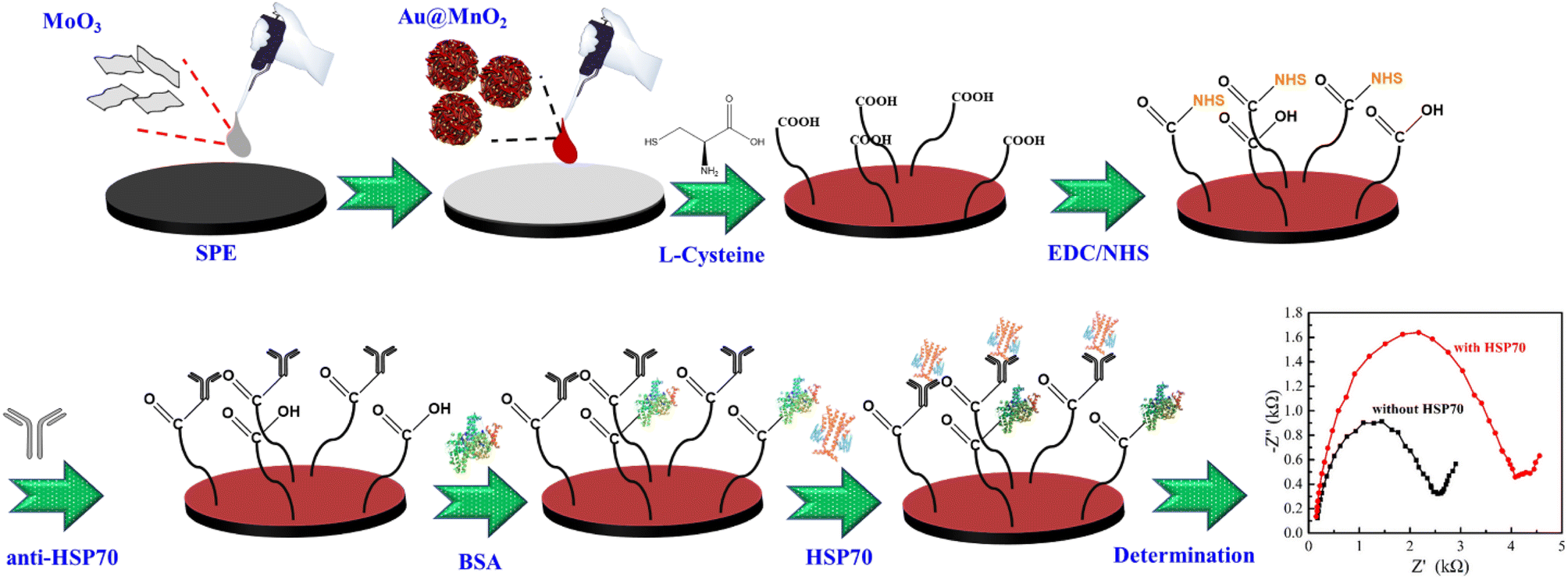 | ||
| Scheme 1 Schematic display of the fabricated HSP70-immunosensor for detecting HSP70. | ||
2.6 Cytotoxicity and HSP70 analysis
Human adenocarcinoma alveolar basal epithelial cells (A549 cells; BCRC 60074, Hsin-Chu, Taiwan) were cultured in Dulbecco's Modified Eagle Medium (DMEM, Gibco, Carlsbad, CA, USA) supplemented with 10% fetal bovine serum (Gibco) and 1% penicillin/streptomycin solution (Gibco) in the incubator filled with humidified atmosphere and 5% CO2 at 37 °C, and the culture medium was changed every 3 days. Briefly, the cell suspensions (5 × 10⁴ mL−1) were cultured in a 48-well at 37 °C in a 5% CO2 atmosphere. After 24 h incubation, the medium was replaced with 500 μL of Paclitaxel (HY-B0015, MedChem Express Monmouth Junction, NJ, USA) in fresh medium (25 μM and 50 μM) and treated at a different time-point. To test the cytotoxicity of Paclitaxel in A549 by PrestoBlue HS (Invitrogen, Carlsbad, CA, USA) as described above. In brief, the PrestoBlue HS was added to the medium at a ratio of 1:9 and placed in the incubator for 2 h for reaction, after which the solution was transferred to a new 96-well microplate. A multi-mode microplate reader (Synergy HTX, BioTek, Winooski, VT, USA) was used to read the fluorescence and excitation/emission was 560/590 nm. All experiments were performed in triplicate and the average was recorded. In addition, the culture medium of the treated cells is collected and analyzed for the concentration of HSP70 by ELISA kit (E-EL-H1863, Elabscience, Houston, TX, USA). The data was used as a verification of the electrical impedance analysis.
2.7 Apparatus
The structures and morphologies of all samples were characterized by XRD and TEM analyses, respectively. The XRD data were obtained by a Bruker D8 Advance diffractometer (Karlsruhe, Germany) with a Ni-filtered Cu Kα radiation (λ = 1.542 Å) and were scanned from 2θ = 5–80° at a scan rate of 1° min−1. The TEM images were acquired using a JEOL JEM-2010 microscope (Tokyo, Japan), which operated at an acceleration voltage of 200 kV. The chemical states and constituent compositions of all samples were determined through XPS analysis using a ULVAC-PHIPHI 5000 instrument (Kanagawa, Japan) with an Al Kα radiation (1486.7 eV) excitation source. The acquired spectra were calibrated against the C 1s electron peak at 284.6 eV. Measurements were conducted at a photoelectron take-off angle of 45°, and data were collected using a fixed pass energy of 23.5 eV (0.2 eV per step) in the spherical capacitance analyzer. The surface morphology of all fabricated electrodes was characterized using a JEOL JSM-7800F field-emission scanning electron microscope (FE-SEM, Tokyo, Japan) operating at an accelerating voltage of 5 kV. Additionally, the microscopic morphology was observed in the lower secondary electron image (LEI) mode, and an integrated energy-dispersive spectrometer (EDS) was employed with the FE-SEM to map the surface elements of the electrodes. An electrochemical analyzer (ACIP100 instrument, Zensor R&D co., Ltd, Taiwan) was utilized to conduct CV and EIS in a conventional three-electrode system with an Ag/AgCl electrode as the reference electrode, an SPE (model: SE-100, Zensor R&D co., Ltd, Taiwan) as the working electrode, and a platinum wire as the counter electrode. The CV and EIS measurements of all electrodes were carried out in 5 mM [K3Fe(CN)6] containing 0.1 M KCl solution. CV was recorded between −0.2 and 0.6 V potential at a scan rate of 50 mV s−1. EIS was performed at a frequency range of 0.2–1000 Hz with 5 mV AC amplitude.3. Results and discussion
3.1 Structure, morphology, and elemental analysis of MoS2, MoO3, MnO2, and Au@MnO2
As presented in Fig. 1, the structures of MoS2, MoO3, MnO2, and Au@MnO2 were characterized via XRD analyses. It can be seen that the XRD pattern of MoS2 (black line) showed two weaker diffraction peaks at 2θ = 32.28°, and 57.08° corresponding to the (100) and (110) crystal planes33,35,36 corresponding to the hexagonal phase and well-matched with JCPDS card no. 73-1508. The peak shapes of these two diffraction peaks are weaker and wider, indicating that MoS2 belongs to the structure of few-layer stacking. The other two stronger diffraction peaks assigned to the (002) and (004) planes were observed at 2θ = 8.7° and 18.12°, respectively. According to literature reports, the (002) and (004) diffraction planes are observed due to the intercalation of ammonium ions increasing the interlayer spacing of MoS2.35,36 The XRD analysis was performed to study the crystal phases of MoO3 nanosheets by annealing at 400 °C for 1 h in air. The obtained MoO3 nanosheets (blue line) were confirmed with the diffraction peaks of 2θ at 12.72°, 23.32°, 25.68°, 27.28°, 29.61°, 33.72°, 35.52°, 38.92°, 45.8°, 46.28°, 49.24°, 52.81°, 55.21°, 58.83°,64.44°, and 69.52° assigned to the (020), (110), (040), (021), (130), (111), (041), (150), (200), (210), (002), (112), (161), (081), (190), and (202) planes, respectively.36,37 The crystal structure of MoO3 nanosheets exhibited an orthorhombic phase (JCPDS card no. 05-0508).37,38 This result means that MoO3 nanosheets were successfully prepared.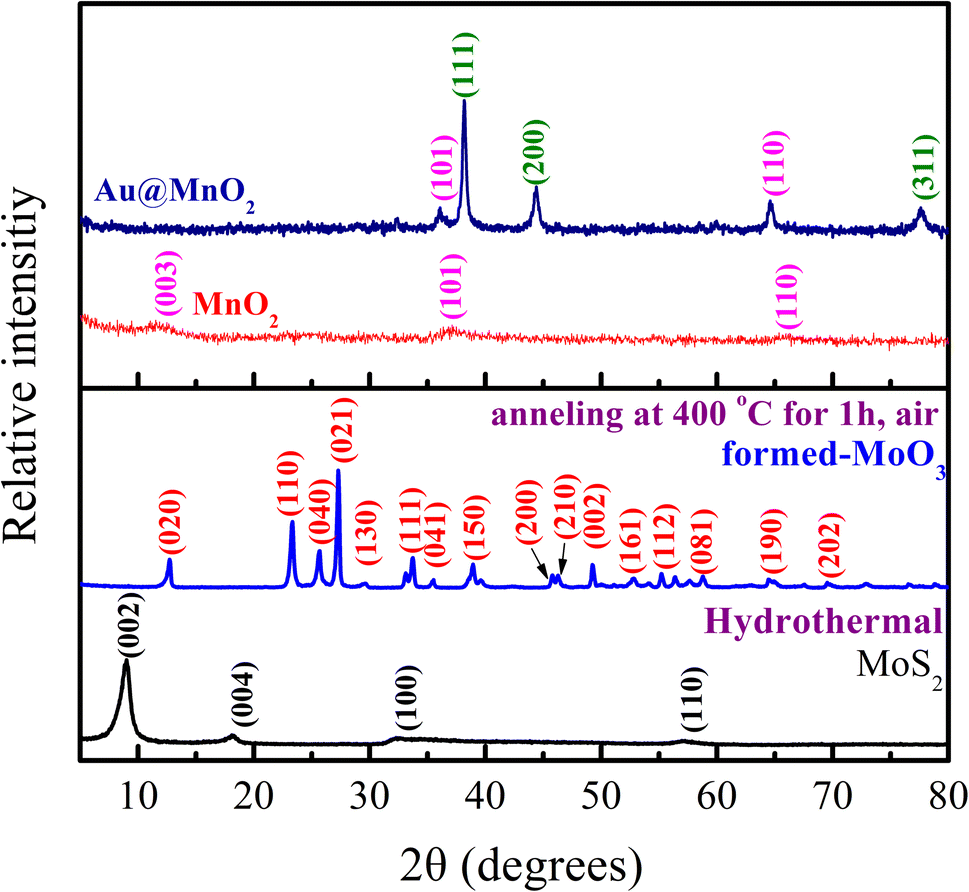 | ||
| Fig. 1 The XRD patterns of MoS2, MoO3, MnO2, and Au@MnO2. | ||
In addition, three weaker diffraction peaks of pure MnO2 (red line) are observed at 2θ = 12.13°, 37.16°, and 65.28°, which are indexed as (003), (101), and (110) planes of the tetragonal phase of MnO2 (JCPDS card no. 52-0556).34,39 The XRD patterns of Au@MnO2 (royal blue line) containing three extra diffraction peaks were different from that of pure MnO2. Three diffraction peaks located at 2θ = 38.5°, 44.6°, and 77.8° correspond to the (111), (200), and (311) planes of face-centered cubic Au (JCPDS card no. 04-0784), respectively.38 The particle size of Au NP is determined through the Debye Scherrer equation, which is shown as follows: d = Kλ/βcosθ, where d is the average particle size, K is the Scherrer constant, λ is the X-ray wavelength of the Cu Kα radiation, θ is the Bragg angle, and β is the full width at half maximum (FWHM) of the peak.40 The particle size of the synthesized Au was calculated at about 16.8 nm. This result suggests that Au@MnO2 nanocomposites were successfully synthesized.
The morphologies of MoS2, MoO3, MnO2, and Au@MnO2 were characterized using TEM, as shown in Fig. 2. The TEM image of MoS2 nanosheets in Fig. 2(a) revealed a rag-like, translucent, and wrinkled morphology, indicating a few-layer structure. The TEM image of MoO3 nanosheets obtained by annealing at 400 °C in the air for 1 h is shown in Fig. 2(b), which exhibited a wrinkle-free and translucent morphology with smooth edges. This suggests that the MoS2 nanosheet morphology was transformed after heat treatment, resulting in MoO3 formation. The TEM image of MnO2 synthesized at 140 °C for 1 h in Fig. 2(c) displayed a nanoflower morphology, composed of nanosheets with folds and crosses in various orientations. The size of the nanoflowers was around 240–250 nm, with darker colors at the core representing the thickest areas. This phenomenon indicates a decrease in electron transfer ability. In addition to the MnO2 nanoflower morphology, Au nanoparticles (NPs) were observed to be dispersed on the surface in Fig. 2(d). The size of the nanoflowers increased to 250–270 nm due to the addition of PVP surfactant, while the size of the Au NPs was approximately 15–20 nm. These results demonstrated the successful preparation of Au@MnO2 nanocomposites, consistent with XRD analysis results.
 | ||
| Fig. 2 The TEM images of (a) MoS2, (b) MoO3, (c) MnO2, and (d) Au@MnO2. | ||
To investigate the chemical states and constituent compositions of MoS2, MoO3, MnO2, and Au@MnO2, XPS spectra were utilized. Survey spectra of MoS2 and MoO3 showed major peaks at S 2p, Mo 3d, and O 1s in Fig. 3(a); however, MoO3 formed by thermal annealing showed no peak at S 2p. Mo 3d XPS data displayed peak locations for MoS2 and MoO3 materials and the peak at 226.2 eV for MoS2 materials was attributed to the S 2s in MoS2 in Fig. 3(b).41,42 The Mo 3d5/2 and Mo 3d3/2 peaks with binding energies of 228.8 and 231.8 eV, respectively, are attributed to Mo4+ in 1T-MoS2 for MoS2 materials.41,42 Two peaks with binding energies of 229.1 and 233.0 eV for MoS2 materials can be ascribed to the 3d5/2 and 3d3/2 of Mo4+ in 2H–MoS2.41,42 The presence of two minor peaks at 232.1 and 235.8 eV in the MoS2 materials indicates the assignment to the 3d5/2 and 3d3/2 states of Mo6+.41,42 There may be two reasons for this phenomenon, one of which is the partial oxidation of Mo atoms at the edges of MoS2 nanosheets.41,42 Another reason may be due to the existence of defects in the crystal plane of MoS2 nanosheets.41,42 In Mo 3d XPS spectra of MoO3 [Fig. 3(b)], the 3d5/2 and 3d3/2 peaks located at 233.2 and 236.3 eV can be attributed to Mo6+ in MoO3.37,38 In comparison, the two additional subtle peaks at 233.0 and 230.6 eV corresponded to the Mo 3d5/2 and Mo 3d3/2 states of Mo5+ within the MoO3 material.37,38 The O 1s XPS spectra of MoS2 and MoO3 are presented in Fig. 3(c). In the O 1s XPS spectra of MoS2, two peaks at 531.8 and 533.4 eV can be attributed to the lattice oxygen O2− (in the stronger Mo–O bond) and surface adsorbed oxygen (–OH group and chemisorbed oxygen-containing species), respectively.41,42 In Fig. 3(c) for MoO3, the observed peaks located at 530.8, 531.6, and 532.4 eV were assigned to the lattice oxygen atoms in MoO3, surface chemisorbed oxygen, and residual hydroxyl oxygen, respectively.37 As observed in Fig. 3(d), the S 2p XPS spectra obtained from MoS2 show two peaks at 161.6 and 162.8 eV, corresponding to S 2p3/2 and S 2p1/2 binding energies for S2−.41,42 The other peak at 169.3 eV for MoS2 can be ascribed to the existence of the S–O bond.43 The S 2p XPS data of MoO3 in Fig. 3(d) showed no peak, confirming that only Mo and O are present in the MoO3 nanosheets. This result proves that MoO3 has been successfully prepared and is consistent with the XRD and TEM results.
 | ||
| Fig. 3 XPS spectra of the (a) survey, (b) Mo 2p, (c) O 1s, and (d) S 2p core levels for MoS2 and MoO3. | ||
Fig. 4(a) presents the XPS survey spectra of MnO2 and Au@MnO2, respectively. For MnO2, it can be observed that there is no peak at Au 4f. Subsequently, we focused on the Mn 2p, O 1s, and Au 4f XPS spectra that were analyzed. Four peaks were observed in the Mn 2p XPS spectrum of MnO2, as shown in Fig. 4(b). Two peaks are attributed to Mn 2p3/2 and Mn 2p1/2 of the Mn3+ and their binding energies are 642.3 and 654.0 eV, respectively.29,44 The other two peak values of 646.2 and 658.1 eV are attributed to Mn4+.29,44 The O 1s XPS spectra of MnO2 are illustrated in Fig. 4(c). The O 1s peak at 529.8 eV is assigned to the oxide structural oxygen (Mn–O–Mn).29,44 The two peaks with binding energies of 531.3 and 532.4 eV were ascribed to the presence of Mn–OH and H–O–H, respectively.29,44 Clearly, a similar phenomenon can also be found in the Mn 2p and O 1s XPS spectra of Au@MnO2 nanocomposites, as shown in Fig. 4(b) and (c). The only difference is the Au 4f XPS spectrum of MnO2 and Au@MnO2 [Fig. 4(d)]. It was confirmed that there is no signal for MnO2 at Au 4f. However, the peaks at 84.2 and 87.8 eV for Au@MnO2 correspond to Au 4f7/2 and Au 4f5/2.29,45 The XPS data further illustrate that fitted peaks at 84.2 and 87.8 eV are because of the Au(0) state.29,45 The other two fitted peaks at 86.0 and 89.6 eV are attributed to the Au(I) state.26,45 These results demonstrated the successful preparation of Au@MnO2 nanocomposites in good agreement with the XRD and TEM results.
 | ||
| Fig. 4 XPS spectra of the (a) survey, (b) Mn 2p, (c) O 1s, and (d) Au 4f core levels for the MnO2 and Au@MnO2 nanocomposites. | ||
3.2 Surface morphology of modified SPE
The SEM images in Fig. 5 illustrate the surface morphologies of the bare SPE, MoO3/SPE, and Au@MnO2/MoO3/SPE configurations. In Fig. 5(a), the original surface of the SPE exhibits a composition of graphite-like flakes. The MoO3/SPE [Fig. 5(b)] showcases irregular sheet-like MoO3 nanosheets characterized by their uneven size and substantial surface area. Fig. 5(c) displays a flower-like MnO2 morphology (size: 240–280 nm), evenly covering the MoO3/SPE surface. To confirm the presence of Au NPs in Au@MnO2/MoO3/SPE, EDS analysis was employed for validation. The EDS spectrum of Au@MnO2/MoO3/SPE [Fig. 5(d)] indicates the presence of five elements: C, O, Mn, Mo, and Au. No significant impurity peaks are observed in the spectrum. In contrast, the bare SPE surface appears relatively smooth when compared to MoO3/SPE and Au@MnO2/MoO3/SPE surfaces. These findings signify the effective utilization of Au@MnO2 and MoO3 for the modification of SPE.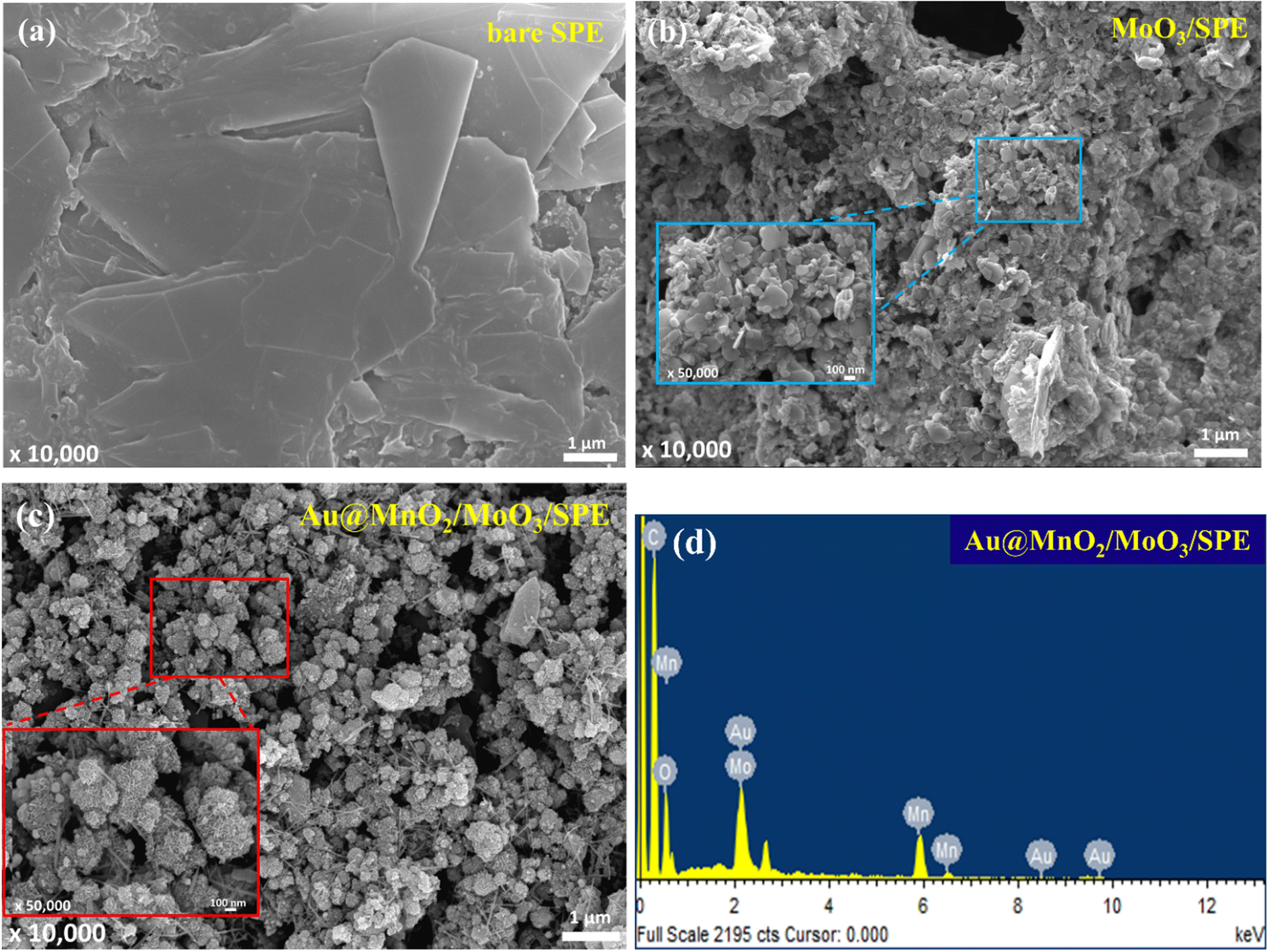 | ||
| Fig. 5 SEM images of the (a) bare SPE, (b) MoO3/SPE, and (c) Au@MnO2/MoO3/SPE. (d) EDS spectrum of Au@MnO2/MoO3/SPE. The insets of (b) and (c) are magnifications. | ||
3.3 Evaluation of electrochemically active surface area for bare SPE and the modified SPE with Au@MnO2/MoO3 nanocomposites
Next, an investigation was conducted to determine the electrochemically active surface area (ECSA) of bare SPE and Au@MnO2/MoO3/SPE. The current related to the anodic peaks was explored using CV with varying scan rates (10, 50, 100, 150, and 200 mV s−1), as depicted in Fig. 6(a). Subsequently, calibration plots depicting the relationship between oxidation peak current (I) and the square root of scan rate (ν1/2) were illustrated for both the bare SPE and the Au@MnO2/MoO3/SPE configuration, as displayed in Fig. 6(b). The electrochemically active surfaces associated with the signal transducer were quantified using the Randles–Sevcik equation: I = 2.69 × 10⁵ × A × D1/2 × n3/2 × ν1/2 × C.46,47 Here, n signifies the number of transferred electrons, A represents the ECSA, D signifies the diffusion coefficient of K3[Fe(CN)6], and C corresponds to the concentration of K3[Fe(CN)6] solution (5 mM). Thus, with the known values of n, D, and C, along with the slope of the I vs. ν1/2 plot, the value of ECSA can be calculated. The results revealed that the ECSA of the bare SPE and the Au@MnO2/MoO3/SPE nanocomposites were measured at 0.0682 and 0.1235 cm2, respectively. These outcomes underscored an enhancement in the electrochemically active surface of the Au@MnO2/MoO3/SPE configuration, showcasing a 1.8-fold improvement compared to the bare SPE. This finding underscores the ability of Au@MnO2/MoO3 nanocomposites to facilitate electron transfer and offer a substantially increased effective specific surface area. | ||
| Fig. 6 (a) CV responses of redox peak currents on different scan rates ranging from 10 to 200 mV s−1. (b) The calibration plots of oxidation peak current (I) versus the square root of scan rate (ν1/2) for bare SPE and Au@MnO2/MoO3/SPE. | ||
3.4 Electrochemical properties of the electrode surface after the stepwise fabrication process
In order to investigate the electrochemical behavior of the HSP70-immunosensor, various modifications of the electrode surface were studied using CV and EIS techniques, as shown in Fig. 7. Fig. 7(a) demonstrates the CV data collected during the electrode surface fabrication steps. The redox current of EN-LC/Au@MnO2/MoO3/SPE was observed to be higher than that of Au@MnO2/MoO3/SPE due to two reasons. Firstly, an active ester intermediate is formed during the EDC/NHS reaction, which exhibits excellent electrochemical activity.48 Secondly, L-cysteine has an NH2 functional group that can interact with negatively charged [Fe(CN)6]3−, thereby increasing electron diffusion.49 Thus, the electrochemical properties of Au@MnO2/MoO3/SPE were improved after modification with L-cysteine and EDC/NHS. The redox current further decreased after immobilizing EN-LC/Au@MnO2/MoO3/SPE with anti-HSP70 due to the formation of an insulating layer on the electrode surface by anti-HSP70, which hinders electron diffusion. BSA was used as a blocking agent to mask non-specific active sites. When BSA was immobilized, the redox current of BSA/anti/EN-LC/Au@MnO2/MoO3/SPE decreased because BSA is a non-conductive substance that reduces the electron diffusion ability. After the complex formation of anti-HSP70 and HSP70, the redox current of HSP70/BSA/anti/EN-LC/Au@MnO2/MoO3/SPE showed a decreasing trend. This indicates that electron diffusion is further hindered in the complex, which causes a greater reduction in redox current. | ||
| Fig. 7 (a) CV and (b) EIS of different stepwise of the electrode fabrication process in 5 mM [K3Fe(CN)6] containing 0.1 M KCl. | ||
The EIS technique is widely employed to study the electrochemical performance of the electrode surface during the progressive manufacturing process. EIS spectra are typically divided into two regions: the high-frequency region (represented by a semicircular curve) and the low-frequency region (represented by the slopes of straight lines known as Warburg impedance).49 The diameter of the semicircle represents the charge transfer resistance (Rct) and is related to the starting point of the semicircular curve, which corresponds to the solution resistance (Rs) between the electrode and the electrolyte solution.49 However, fitting EIS data involves using an appropriate equivalent circuit, and in this case, the Randles equivalent circuit is composed of four components, including (i) charge transfer resistance (Rct), (ii) Warburg impedance (ZW), (iii) solution resistance (Rs), and (iv) constant phase element (CPE),50 as shown in Fig. 7(b) inset. These parameters contribute to the interpretation of the observed impedance behavior. The EIS spectra of the fabricated HSP70-immunosensor stepwise are shown in Fig. 7(b), and the Rct-value after modifying the electrode surface through each stage was calculated according to the rules described above.
The Rct-value of the Au@MnO2/MoO3/SPE was 1.38 kΩ, and after modifying the electrode surface with L-cysteine molecules and the reaction process of EDC/NHS, the Rct-value was reduced to 0.72 kΩ. The introduction of L-cysteine molecules improved the charge transfer capability by interacting with the negatively charged [Fe(CN)6]3−.49 Additionally, the formation of an active ester intermediate during the reaction between EDC and NHS could also improve the electrochemical activity and charge transfer ability.48 The Rct-value of antiHSP70/EN-LC/Au@MnO2/MoO3/SPE was increased to 1.74 kΩ when the anti-HSP70 was immobilized on the electrode surface. This is because the antiHSP70 acted as an insulating layer that hindered the charge transfer ability. After immobilizing BSA on the antiHSP70/EN-LC/Au@MnO2/MoO3/SPE, the Rct-value increased from 1.74 to 2.43 kΩ, indicating that BSA successfully blocked the reactive sites. After loading HSP70 on the BSA/antiHSP70/EN-LC/Au@MnO2/MoO3/SPE surface, the Rct-value was increased to 4.47 kΩ due to the formation of an antibody (anti-HSP70)-antigen (HSP70) complex layer on the electrode that hindered the transfer of electrons. CV and EIS data confirmed the successful fabrication of the HSP70-immunosensor, and the agreement between the CV and EIS analysis results indicated that the immunosensor was an excellent platform for detecting HSP70 biomarkers.
3.5 Optimization studies of the HSP70-immunosensor
To achieve accurate and efficient sensing performance of the HSP70-immunosensor, the experimental conditions were optimized using the EIS technique. The concentration of anti-HSP70, incubation time of anti-HSP70, incubation time of BSA, and incubation time of HSP70 were all optimized. The change in electron transfer resistance (ΔRct) was calculated using the equation: ΔRct = Rct (HSP70) − Rct (BSA). The concentration of anti-HSP70 on the EN-LC/Au@MnO2/MoO3/SPE surface was increased until the ΔRct-value reached saturation at 30 ng mL−1. The optimal incubation time for antiHSP70 was found to be 60 min, where the ΔRct-value was enhanced. The BSA incubation time was optimized to be 30 min as it effectively blocked non-specific sites. The optimal HSP70 incubation time was found to be 60 min, as the binding efficiency of the antibody to HSP70 tended to be stable after this time. The optimal experimental conditions were determined to be: 30 μg mL−1 antiHSP70 concentration, 60 min incubation time for antiHSP70, 30 min incubation time for BSA, and 60 min interaction time for antiHSP70 and HSP70.The EN-LC/Au@MnO2/MoO3/SPE surface was used to optimize the concentration and incubation time of anti-HSP70 for effective binding to NHS. The results in Fig. 8(a) show that as the anti-HSP70 concentration increases, the ΔRct-value also increases, indicating successful binding to NHS. However, the ΔRct-value was stabilized and the binding of the antiHSP70 to NHS achieved saturation when the concentration reached 30 ng mL−1. Therefore, 30 μg mL−1 was chosen as the optimal anti-HSP70 concentration. In the meanwhile, the incubation time of anti-HSP70 was optimized, and 60 min was the optimal incubation time for effective antibody binding, as shown in Fig. 8(b), since the ΔRct-value reached the highest at 60 min incubation and dropped thereafter. The BSA incubation time was also investigated, as shown in Fig. 8(c), based on the optimal antibody concentration and incubation time, and it was found that 30 min was sufficient to block non-specific sites. The different BSA incubation times of 15, 30, 45, 60, and 75 min were used to detect 100 ng mL−1 HSP70; in the results, the ΔRct-value tended to be stable with BSA incubation time greater than 30 min. Finally, we have also optimized the HSP70 incubation time [Fig. 8(d)], and it was found that after 60 min, the binding efficiency of the anti-HSP70 antibody to the HSP70 antigen tended to be stable since the ΔRct-value saturated. Based on these results, the optimal experimental conditions were determined to be an anti-HSP70 concentration of 30 μg mL−1, an anti-HSP70 incubation time of 60 min, an incubation time of 30 min for BSA, and an anti-HSP70 and HSP70 interaction time of 60 min.
 | ||
| Fig. 8 Optimization of (a) concentration of antiHSP70, (b) incubation time for antiHSP70, (c) incubation time of BSA, and (d) incubation time for HSP70 (n = 5). | ||
3.6 Analytical performance of the fabricated HSP70-immunosensor
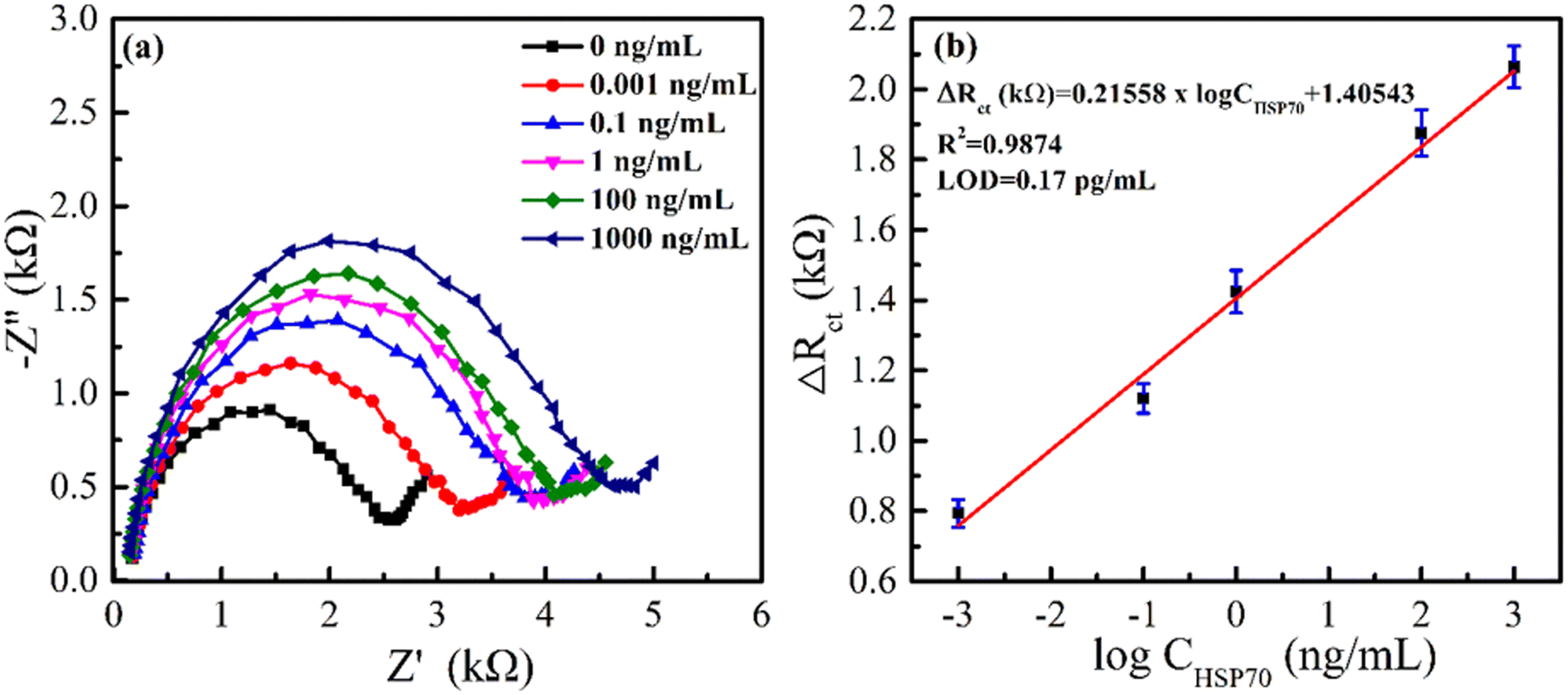
In this study, an HSP70-immunosensor was created and tested using EIS methods. The immunosensor was exposed to varying concentrations of HSP70 antigen, and the resulting changes in the immunosensor's electrical properties were analysed. As seen in Fig. 9(a), the diameter of the semicircle increased as the concentration of HSP70 antigen increased within the range of 0.001–1000 ng mL−1, and it also indicated that the ΔRct-value increased. This increase is attributed to the formation of HSP70 antigen-antiHSP70 complexes on the surface of the immunosensor at high antigen concentrations. Fig. 9(b) shows a linear relationship between the immunosensor response and logarithm of HSP70 concentrations in the range of 0.001 to 1000 ng mL−1 with the linear regression equation of ΔRct (kΩ) = 0.21558 × logCHSP70 (ng mL−1) + 1.40543 and correlation coefficient of 0.9874. The limit of detection (LOD) was calculated by the following equation: LOD = 3σ/b, where σ is the standard deviation of response, and b is the slope of the regression equation.51 The LOD was determined to be 0.17 pg mL−1.
 | ||
| Fig. 9 (a) EIS responses of proposed immunosensor at different concentrations of HSP70. (b) Calibration plot between ΔRct and logCHSP70. | ||
Table 1 displays a comparison of the linear detection range and LOD of our HSP70-immunosensor with other electrochemical immunosensors used to detect HSP70 biomarkers. The immunosensor in this study exhibits the widest linear detection range among the compared immunosensors. According to previous reports, the average concentrations of HSP70 detectable in healthy humans and cancer patients are 2.2 ng mL−1 and 5.3 ng mL−1, respectively.2,17 We found that some immunosensors in Table 1 have a linear detection range that can reach the fg mL−1 level, but their upper limit does not cover the average concentration of HSP70 detectable in healthy humans and cancer patients. This can cause significant deviation when detecting real samples. The immunosensor in this study has a LOD value that might not be the lowest when compared to previous reports, but it is still sufficient for detecting real samples. The improved detection capability of our HSP70-immunosensor can be attributed to the strong biomolecular adsorption ability of Au NPs, which promotes electron transfer ability between biomaterials and the electrode surface, high charge transfer ability and large active surface area of MnO2, and the excellent electrochemical performance, surface charge performance, and better biocompatibility of MoO3.
| Samples | Biorecognition element | Methods | LOD | Linear range | Refs. |
|---|---|---|---|---|---|
| Graphite/PMMA modified plastic chip electrode (PCE) | Antibody | DPV | 3.5 pg mL−1 | 0.01–1000 ng mL−1 | 2 |
| GO modified GCE | Antibody | EIS | 0.765 fg mL−1 | 12–144 fg mL−1 | 12 |
| AuNP modified ITO | Antibody | EIS | 0.0618 fg mL−1 | 1–166 fg mL−1 | 18 |
| Porous graphene modified GCE | Antibody | DPV | 0.02 ng mL−1 | 0.0448–100 ng mL−1 | 19 |
| Fullerene C60 modified GCE | Antibody | EIS | 0.273 pg mL−1 | 0.8–12.8 pg mL−1 | 20 |
| Polyaniline functionalized graphene quantum dots modified GCE | Antibody | DPV | 0.05 ng mL−1 | 0.0976–100 ng mL−1 | 21 |
| Ag NP/TiO2 nanotube modified Ti foil | Antibody | EIS | 0.48 ng mL−1 | 0.1–100 ng mL−1 | 22 |
| Graphene oxide/acropora-like gold modified GCE | Aptamer | DPV | 2 pg mL−1 | 5 pg mL−1–75 ng mL−1 | 47 |
| Lady fern-like gold modified gold electrode | Aptamer | DPV | 0.02 ng mL−1 | 0.05–75 ng mL−1 | 52 |
| 11-Mercaptoundecanoic acid (MUA)-PSYVAFTDT modified gold electrode | Peptide | SWV | — | 0.2–2 nU mL−1 | 53 |
| 3-Aminopropyltriethoxysilane (APTES)/glutaraldehyde modified porous silicon | Antibody | UV-vis | 1.29 μg mL−1 | 3–500 μg mL−1 | 54 |
| Au@MnO2/MoO3 modified SPE | Antibody | EIS | 0.17 pg mL−1 | 0.001–1000 ng mL−1 | This work |
Furthermore, it is worth noting that during the early stages of cancer surgery, HSP70 concentrations can significantly rise, reaching levels exceeding 100 ng mL−1.17 Consequently, other HSP70-biosensors with overly narrow linear ranges would be inadequate for monitoring therapeutic progress, given their inability to accommodate such elevated concentrations. This highlights the necessity for a broader linear range in the design of detection tools aimed at precise and reliable treatment tracking.
3.7 Selectivity, reproducibility, and stability of the HSP70 immunosensor
The selectivity of immunosensors is a crucial parameter that needs to be evaluated. To assess the selectivity, the HSP70 immunosensor was fabricated and incubated with different interfering antigens (HSP60, HSP90, and HSP110) at a concentration of 100 ng mL−1, followed by EIS analysis. Fig. 10(a) presented that the ΔRct of the HSP70 antigen was higher than that of other antigens, indicating that the impedance in the electrochemical system was greater for the HSP70 antigen. The above results showed the excellent selectivity of the immunosensor against HSP70 antigens. To examine the reproducibility of the prepared HSP70 immunosensor, five detections were performed under the same conditions for each concentration of the antigen. Fig. 10(b) shows the ΔRct-values for different antigen concentrations on the immunosensor fabricated by the proposed method. The relative standard deviation (RSD) for different antigen concentrations was analyzed to be approximately 4.97%, 4.27%, and 3.51% for 0.001, 1, and 100 ng mL−1 incubations of HSP70 antigens, respectively. This result demonstrates that the fabricated immunosensor has excellent reproducibility. The stability of the immunosensor was also evaluated by storing the fabricated HSP70 immunosensors at 4 °C and testing for HSP70 antigen every two days [Fig. 10(c)]. The ΔRct-values changed to 92.12% of their original values for 100 ng mL−1 HSP70 antigen concentration after 14 days, indicating that the stability of the immunosensor was acceptable. These results demonstrate the good selectivity, reproducibility, and stability of the HSP70 immunosensor.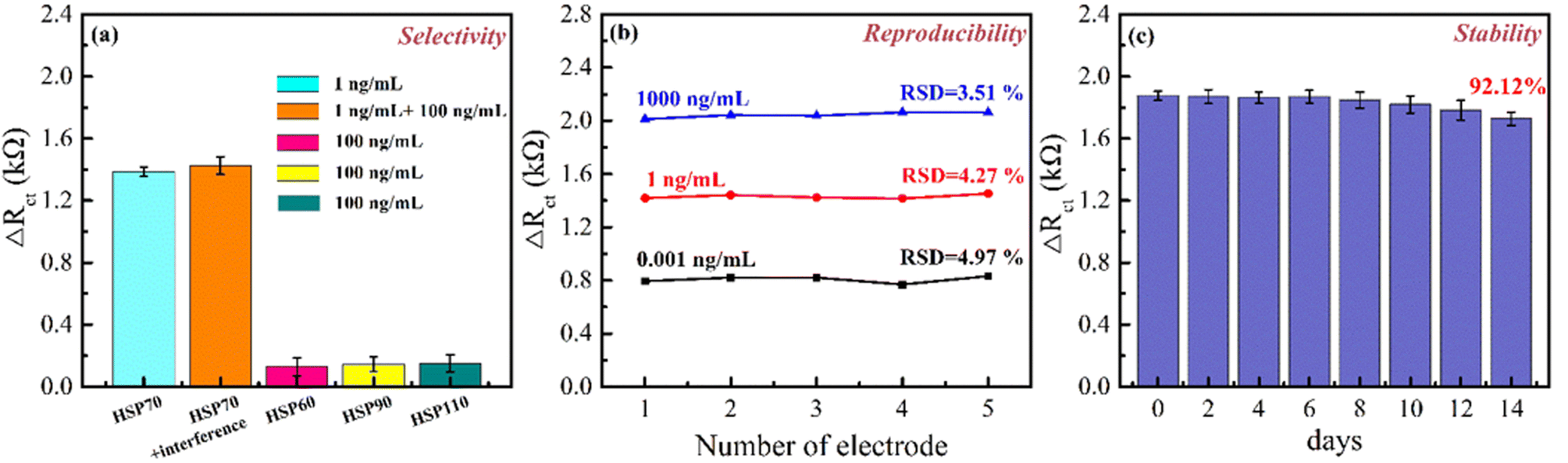 | ||
| Fig. 10 (a) Selectivity, (b) reproducibility, and (c) stability of the fabricated HSP70 immunosensors (n = 5). | ||
3.8 Application of the immunosensor in lung adenocarcinoma cell line
In order to understand the clinical application of this electrochemical immunosensor, we designed a cell cytotoxicity model by co-culture A549 (lung carcinoma epithelial cell line) with paclitaxel (a chemotherapy for lung carcinoma cancer) and adapted our immunosensor to detect the HSP70 levels released from A549 death or A549 oxidative stress. First, we evaluated the cytotoxicity and HSP70 secretion levels in cell culture with different concentrations paclitaxel (0, 25, and 50 μM correspond to P0, P25, and P50) for 1 day and 3 days (Fig. 11) to observe the behavior of A549 to paclitaxel. On day 1, there was no cytotoxicity in A549 among P0 and P25 (p > 0.05) detected and P50 group was significantly lower than P0 (p < 0.05), which indicated some mild toxicity. The phenomenon observed in the paclitaxel demonstrated significant differences between the P25 and P50 with 21.3 ± 5.5% and 37.1 ± 5.6% cytotoxicity in the A549 after treatment for 3 days, respectively. This result was also reflected in the protein secretion, and there was no significant difference in protein secretion on day 1 among the three groups. After the cells were treated for 3 days, the HSP70 of P25 and P50 were 2.9 times and 4.8 times that of P0, respectively. Past studies have indicated that HSP70 is a biomarker released in the early stage of cell death. Therefore, if the protein can be accurately detected in the early stage of cell death processing, it will be of great help to the application of precision medicine in the future.55 However, our results show that although P50 has close to 15% cell death, there is no significant difference in the analysis of the HSP70 protein. The evaluation is because the detection limit of the ELISA kit used cannot analyze HSP70 at a concentration that is too low, so the sensitive sensing biosensor is needed to have a chance of solving this problem. | ||
| Fig. 11 (a) Live/dead assays of the A549 cell line obtained after exposure of the cells to different concentrations of paclitaxel for up to 3 days. (b) HSP 70 concentrations versus culture time obtained using the calibration curve. | ||
Subsequently, the proposed HSP70 immunosensor was utilized to detect the HSP70 levels in cell culture with 0, 25, and 50 μM paclitaxel after 1 day. According to the standard addition method proposed in previous studies, the original HSP70 concentration in lung adenocarcinoma cell lines after using paclitaxel can be measured. These samples were spiked with different HSP70 proteins (0, 0.1, 1, and 10 ng mL−1) to evaluate the accuracy and utility of the HSP70 immunosensor, as summarized in Table 2. These results show that the HSP70 immunosensor has good accuracy. However, the HSP70 concentrations in lung adenocarcinoma cell lines are detected to be approximately 0.0294, 0.0439, and 0.0638 ng mL−1 for 0, 25, and 50 μM addition of paclitaxel, respectively. With the increase of paclitaxel, a slight increase in the concentration of HSP70 can be detected, indicating that the damage to the cell line can increase the concentration of HSP70. This phenomenon is consistent with the literature.17 It is indicated that the proposed HSP70 immunosensor can detect the concentration of HSP70 on the first day, indicating that the immunosensor is better than ELISA in the early detection stage. Therefore, the prepared HSP70 immunosensor in the early detection stage can be a practical analysis tool for the HSP70 protein in organ-on-a-chip and clinical applications.
| Paclitaxel (μM) | Spiked (ng mL−1) | Detected (ng mL−1) | Recovery (%) | RSD (%) |
|---|---|---|---|---|
| 0 | — | 0.0294 | — | — |
| 0.1 | 0.154 | 119.01 | 5.34 | |
| 1 | 1.156 | 112.30 | 6.41 | |
| 10 | 10.86 | 108.28 | 5.15 | |
| 25 | — | 0.0439 | — | — |
| 0.1 | 0.17 | 118.13 | 6.21 | |
| 1 | 1.19 | 114.00 | 6.74 | |
| 10 | 10.78 | 107.33 | 5.73 | |
| 50 | — | 0.0638 | — | — |
| 0.1 | 0.19 | 116.00 | 8.43 | |
| 1 | 1.25 | 117.50 | 7.17 | |
| 10 | 11.52 | 114.47 | 7.51 |
4. Conclusions
In this study, a facile approach for the synthesis of MoO3 nanosheets was developed by thermally oxidizing MoS2 nanosheets in air, followed by thermal annealing. Au@MnO2 nanocomposites were then prepared using a combined approach of hydrothermal and in situ chemical synthesis methods. The structures, morphologies, and elemental analysis of MoO3 and Au@MnO2 were characterized using XRD, TEM, and XPS. To modify SPE, the novel Au@MnO2/MoO3 nanocomposites were fabricated using a solution-mixing process, where the HSP70-antibodies were bound to EDC/NHS by L-cysteine and acted as a biorecognition element. The fabrication process of the immunosensor was carried out using CV and EIS techniques. The anti-HSP70-HSP70 complex layer on the immunosensor increased impedance, which could be used as a signal for determining antigen concentration. The fabricated HSP70-immunosensor had a good linear dynamic range of 0.001 ng mL−1 to 1000 ng mL−1 with a LOD of 0.17 pg mL−1 and did not require a secondary antibody for labeling. The immunosensor demonstrated acceptable selectivity, low detection limit, excellent reproducibility, and good stability. Moreover, the immunosensor successfully detected a very low level of HSP70 in the lung adenocarcinoma cell line after treatment with paclitaxel, indicating its potential in early detection of the HSP70 biomarker for organ-on-a-chip and clinical applications.4.1 Study limitations
Despite the excellent electrochemical sensing performance of the electrochemical immunosensor designed for HSP70, it is crucial to emphasize that this protein is not exclusively targeting lung cancer and could be associated with other diseases. On the other hand, this study selected lung adenocarcinoma cells as a model, inducing cell death using paclitaxel to observe variations in the concentration of the apoptosis-related protein HSP70. It is anticipated that this testing model can be extrapolated to other cancer cell lines, thereby providing a universal approach for potential applications across different types of cancer (as most cancer cell apoptosis results in the production of HSP70 and other apoptosis-related proteins). We hope that this HSP70 immunosensor can serve not only as a diagnostic tool but also as a means for treatment monitoring.Author contributions
Y. A. C. and M. Y. S. methodology, validation, investigation, formal analysis, writing – original draft, preparation, and writing – review & editing; C. C. H., S. W. Y., I. W. P C., Y. Y. S., and Y. F. S. helped with data analysis and interpretation; Y. W. C. conceptualization, funding acquisition, project administration, and writing – review & editing.Conflicts of interest
The authors declare that they have no conflicts of interest.Acknowledgements
This work was supported by the Ministry of Science and Technology (Taiwan, R.O.C.) under Grant No. MOST109-2221-E039-001-MY3 and MOST 110-2221-E-039-012. The authors gratefully acknowledge the use of EM004200, EM0000019200, ESCA00003100, and XRD000004600 of MOST 108-2731-M-005-001- belonging to the Instrument Center of National Chung Hsing University. We thank them for their help with SEM, XPS, XRD, and TEM measurements. The China Medical University Hospital grants (DMR-111-179).Notes and references
- F. Bray, J. Ferlay, I. Soerjomataram, R. L. Siegel, L. A. Torre and A. Jemal, CA Cancer J. Clin., 2018, 68, 394–424 CrossRef PubMed.
- N. H. Maniyaa, K. Parashara, L. N. Kadam and D. N. Srivastava, J. Taiwan Inst. Chem. Eng., 2021, 128, 11–19 CrossRef.
- F. Cui, Z. Zhou and H. S. Zhou, J. Electrochem. Soc., 2020, 167, 37525 CrossRef CAS.
- N. Banaei, A. Foley, J. M. Houghton, Y. Sun and B. Kim, Nanotechnology, 2017, 28, 455101 CrossRef PubMed.
- N. L. Henry and D. F. Hayes, Mol. Oncol., 2012, 6, 140–146 CrossRef CAS PubMed.
- H. Qi, Z. Yukun, F. Xiangning and W. Tangchun, J. Huazhong Univ. Sci. Technol. Med. Sci., 2005, 25, 693–695 CrossRef PubMed.
- K. Suzuki, Y. Ito, K. Wakai, M. Kawado, S. Hashimoto, N. Seki, M. Ando, Y. Nishino, T. Kondo, Y. Watanabe, K. Ozasa, T. Inoue and A. Tamakoshi, Cancer Epidemiol., Biomarkers Prev., 2006, 15, 733–1737 CrossRef PubMed.
- M. Zimmermann, S. Nickl, C. Lambers, S. Hacker, A. Mitterbauer, K. Hoetzenecker, A. Rozsas, G. Ostoros, V. Laszlo, H. Hofbauer, F. Renyi-Vamos, W. Klepetko, B. Dome and H. J. Ankersmit, Clin. Chim. Acta, 2012, 413, 1115–1120 CrossRef CAS PubMed.
- B. Bukau and A. L. Horwich, Cell, 1998, 92, 80928–80937 CrossRef PubMed.
- J. G. Kiang and G. C. Tsokos, Pharmacol. Ther., 1998, 80, 183–201 CrossRef CAS PubMed.
- M. Y. Sherman and V. L. Gabai, Oncogene, 2015, 34, 4153–4161 CrossRef CAS PubMed.
- B. Özcan and M. K. Sezgintürk, Talanta, 2016, 160, 367–374 CrossRef PubMed.
- D. R. Ciocca and S. K. Calderwood, Cell Stress Chaperones, 2005, 10, 86–103 CrossRef CAS PubMed.
- M. P. Mayer and B. Bukau, Cell. Mol. Life Sci., 2005, 62, 670–684 CrossRef CAS PubMed.
- J. P. Hendrick and F. U. Hartl, Annu. Rev. Biochem., 1993, 62, 349–384 CrossRef CAS PubMed.
- G. D. Lianos, G. A. Alexiou, A. Mangano, A. Mangano, S. Rausei, L. Boni, G. Dionigi and D. H. Roukos, Cancer Lett., 2005, 360, 114–118 CrossRef PubMed.
- M. Gehrmann, H. M. Specht, C. Bayer, M. Brandstetter, B. Chizzali, M. Duma, S. Breuninger, K. Hube, S. Lehnerer, V. V. Phi, E. Sage, T. E. Schmid, M. Sedelmayr, D. Schilling, W. Sievert, S. Stangl and G. Multhoff, Radiat. Oncol., 2014, 9, 131 CrossRef PubMed.
- M. N. S. Karaboğa, Ç. S. Şimşek and M. K. Sezgintürk, Biosens. Bioelectron., 2016, 84, 22–29 CrossRef PubMed.
- B. Sun, J. Cai, W. Li, X. Gou, Y. Gou, D. Li and F. Hu, Biosens. Bioelectron., 2018, 111, 34–40 CrossRef CAS PubMed.
- B. Demirbakan and M. K. Sezgintürk, J. Electroanal. Chem., 2016, 783, 201–207 CrossRef CAS.
- B. Sun, Y. Wang, D. Lia, W. Li, X. Gou, Y. Gou and F. Hu, Mater. Sci. Eng. C, 2020, 111, 110797 CrossRef CAS PubMed.
- M. Nycz, K. Arkusz and D. G. Pijanowsk, Materials, 2021, 14, 3767 CrossRef CAS PubMed.
- W. Li, G. C. Fan, X. Fan, R. Zhang, L. Wang, W. Wang and X. Luo, J. Mater. Chem. B, 2019, 7, 5842–5847 RSC.
- I. A. D. Castro, R. S. Datta, J. Z. Ou, A. Castellanos-Gomez, S. Sriram, T. Daeneke and K. Kalantar-Zadeh, Adv. Mater., 2017, 29, 701619 CrossRef PubMed.
- B. Hu, L. Mai, W. Chen and F. Yang, ACS Nano, 2009, 3, 478–482 CrossRef CAS PubMed.
- H. Li, L. Mcrae, C. J. Firby, M. Al-Hussein and A. Y. Elezzabi, Nano Energy, 2018, 47, 130–139 CrossRef CAS.
- S. Balendhran, S. Walia, H. Nili, J. Z. Ou, S. Zhuiykov, R. B. Kaner, S. Sriram, M. Bhaskaran and K. Kalantar-Zadeh, Adv. Funct. Mater., 2013, 23, 3952–3970 CrossRef CAS.
- S. Augustine, P. Kumar and B. D. Malhotra, ACS Appl. Bio. Mater., 2019, 2, 5366–5378 CrossRef CAS PubMed.
- A. G. M. Silva, T. S. Rodrigues, E. G. Candido, I. C. D. Freitas, A. H. M. Silva, H. V. Fajardo, R. Balzer, J. F. Gomes, J. M. Assaf, D. C. D. Oliveira, N. Oger, S. Paul, R. Wojcieszak and P. H. C. Camargo, J. Colloid Interface Sci., 2018, 530, 282–291 CrossRef PubMed.
- A. K. Mohiuddin and S. Jeon, Appl. Surf. Sci., 2022, 592, 153162 CrossRef CAS PubMed.
- A. Mocanu, I. Cernica, G. Tomoaia, L. D. Bobos, O. Horovitz and M. Tomoaia-Cotisel, Colloids Surf., A, 2009, 338, 93–101 CrossRef CAS.
- J. W. Lee, S. R. Choi and J. H. Heo, ACS Appl. Mater. Interfaces, 2021, 13, 42311–42328 CrossRef CAS PubMed.
- X. Feng, Q. Tang, J. Zhou, J. Fang, P. Ding, L. Sun and L. Shi, Cryst. Res. Technol., 2013, 48, 363–368 CrossRef CAS.
- X. Zhang, H. Zhi, M. Zhu, F. Wang, H. Meng and L. Feng, Biosens. Bioelectron., 2021, 180, 113146 CrossRef CAS PubMed.
- Q. Liu, X. Li, Q. He, A. Khalil, D. Liu, T. Xiang, X. Wu and L. Song, Small, 2015, 11, 5556–5564 CrossRef CAS PubMed.
- K. Silambarasana, J. Archanaa, S. Harisha, M. Navaneethan, R. S. Ganesh, S. Ponnusamy, C. Muthamizhchelvan and K. Harac, J. Mater. Sci. Technol., 2020, 51, 94–101 CrossRef.
- X. Hou, Y. Gao, H. Ji, S. Yi, Z. Zhang, T. Li, Y. Wang, L. Yuan, R. Zhang, J. Sun and D. Chen, J. Colloid Interface Sci., 2022, 605, 624–636 CrossRef CAS PubMed.
- N. Zeng, D. G. Hopkinson, B. F. Spencer, S. G. McAdams, A. A. Tedstone, S. J. Haigh and D. J. Lewis, Chem. Commun., 2019, 55, 99–102 RSC.
- Y. Meng, W. Song, H. Huang, Z. Ren, S. Y. Chen and S. L. Suib, J. Am. Chem. Soc., 2014, 136, 11452–11464 CrossRef CAS PubMed.
- M. Sivagami and I. V. Asharani, Inorg. Chem. Commun., 2022, 145, 110054 CrossRef CAS.
- X. Q. Qiao, F. C. Hu, F. Y. Tian, D. F. Hou and D. S. Li, RSC Adv., 2016, 6, 11631 RSC.
- L. Tian, R. Wu and H. Liu, J. Mater. Sci., 2019, 54, 9656–9665 CrossRef CAS.
- S. S. Kim, L. Britcher, S. Kumar and H. J. Griesser, Sains Malays, 2018, 47, 1913–1922 CrossRef.
- J. Mondal and S. K. Srivastava, ACS Appl. Nano Mater., 2020, 3, 11048–11059 CrossRef CAS.
- M. Nasrollahzadeh, N. Shafiei, M. Eslamipanah, P. Fakhri, B. Jaleh, Y. Orooji and R. S. Varma, Clean Technol. Environ. Policy, 2020, 22, 1715–1724 CrossRef CAS.
- A. J. Bard and L. R. Faulkner, Electrochem. Methods, 2001, 2, 580–632 Search PubMed.
- M. Negahdary, M. H. Hirata, S. K. Sakata, R. M. Ciconelli, G. M. Bastos, J. B. Borges, H. S. Thurow, A. T. S. Junior, M. F. Sampaio, L. B. Guimarães, B. S. Maeda and L. Angnes, Anal. Chim. Acta, 2023, 1242, 340716 CrossRef CAS PubMed.
- E. Asav and M. K. Sezgintürk, Int. J. Biol. Macromol., 2014, 66, 273–280 CrossRef CAS PubMed.
- N. Olgaç, Y. Şahin and L. Liv, Analyst, 2022, 147, 4462–4472 RSC.
- S. K. Mishra, A. K. Srivastava and D. Kumar, RSC Adv, 2014, 4, 21267–21276 RSC.
- A. K. Rao and S. E. Creager, Anal. Chim. Acta, 2008, 628, 190–197 CrossRef CAS PubMed.
- M. Negahdary and L. Angnes, Talanta, 2022, 246, 123511 CrossRef CAS PubMed.
- X. Ding, H. Li, H. Xie, Y. Huang, Y. Hou, Y. Yin and G. Li, Biosens. Bioelectron., 2013, 47, 75–79 CrossRef CAS PubMed.
- N. H. Maniya and D. N. Srivastava, Mater. Sci. Semicond. Process., 2020, 115, 105126 CrossRef CAS.
- S. Basu, R. J. Binder, R. Suto, K. M. Anderson and P. K. Srivastava, Int. Immunol., 2000, 12, 1539–1546 CrossRef CAS PubMed.
Footnote |
| † These authors contributed equally to this work. |
| This journal is © The Royal Society of Chemistry 2023 |