DOI:
10.1039/D3RA03115B
(Paper)
RSC Adv., 2023,
13, 26179-26188
Tailored efficient energy transfer Tb3+, Eu3+ activated/co-activated LiAl(PO3)4 phosphor by substitution of alkali metals: the effect of charge compensation
Received
10th May 2023
, Accepted 21st August 2023
First published on 1st September 2023
Abstract
Phosphites are the new emerging candidates in the field of luminescence in the modern era. In the present investigation, Tb3+/Eu3+ activated/co-activated LiAl(PO3)4 phosphor was prepared by a wet chemical method, and the effect of R+ (Na+, K+) ions on photoluminescence (PL) properties of these phosphors are investigated. Phase identification and crystal structure of the prepared phosphor were determined using XRD and Rietveld refinement, respectively. Morphological study and elemental analysis of the proposed phosphor with elemental analysis of the sample were performed using SEM and EDS. The PL properties of the proposed phosphor showed three simultaneous emission peaks in the visible range, giving color-tunable emission. The charge compensation of Na+ and K+ ions make a significant impact on the PL intensity of Tb3+, Eu3+ co-activated LiAl(PO3)4 phosphors. The PL intensity of Tb3+, Eu3+ co-activated LiAl(PO3)4 phosphors was significantly enhanced by factors 1.2 and 1.4 when Na+ and K+ charge compensators, respectively, were introduced. To manifest the charge compensation effect of alkali metals the optimum intense sample in the co-doped sample was used. These results indicate the potential candidacy of the studied phosphor for further improvement in PL properties for application in solid-state lighting.
1. Introduction
The scientific world has been paying close attention to lanthanide-based phosphors because of their outstanding photophysical characteristics,1 including narrow emission,2 significant Stokes shift,3 strong photostability,4,5 photochromic luminescence,6,7 and long lifespan.5,8,9 They are employed in almost all areas of science and technology, including solid-state lighting,10–13 scintillators,14,15 photonics,16–18 detectors,19,20 catalytic processes,21,22 vitality,23,24 and environmentalism,25 due to their exceptional photophysical properties. The lanthanides Dy3+, Tb3+, and Eu3+ ions exhibit extremely different emission bands in the visible and NUV regions, making them a desirable contender for WLEDs and solar power.26–33 Nevertheless, the performance of the doping and the kind of inorganic host in which it was successfully doped determine the luminescence performance, longevity, and quantum yield.34,35 The inorganic oxides, phosphates, and fluoride phosphors have a number of advantageous characteristics that make them suitable luminescence hosts. The simplicity of the synthesis, lack of toxicities, high level of structural, chemical, and mechanical integrity, diversity of structure, photochromic optical characteristics and endurance, and self-activated luminescence are a few of the characteristics.36–40 The host-dopant energy transfer exerts considerable control over the luminescence lifespan and quantum efficiency of systems that are doped with lanthanides to produce luminous hosts.41,42 The choice of dopant and host has been shown in multiple papers from all over the world on Ln3+-activated phosphates to have a very large impact on the host-to-dopant energy transfer efficiency. Overall, when the size of the dopant can be accommodated inside the host lattice, the host-to-dopant exchange of energy is enhanced. A number of additional difficulties in producing luminescence hosts with the best optical properties are the strain and defect development caused by the size and charge imbalance among rare earth ions such as lanthanides and the host matrices.
A monovalent alkali metal ion co-doped as a charge compensator is considered the most popular solution to this problem.43,44 The generation of cationic vacancies, which could offer non-radiative pathways and lower the light output of such phosphors, is thought to result from trivalent doping at a divalent site.45–47 Lithium, sodium, and potassium are the most commonly used alkali metals. To observe the impact of the charge compensation effect, many rare earth-activated luminous phosphors are currently being researched. Sobierajska et al.48 examined the impact of substituting lithium as a charge compensator on the luminescence properties of Ca10(PO4)6F2:Eu3+ phosphor. In order to look into the site occupancy choice for the charge compensation co-doping, the concentration of Eu3+ ions was 1 mol% and the concentration of Li+ ions was between 0.5 and 5 mol%. According to the luminescence characteristics of Eu3+ ions, the Ca1 site is predominantly substituted for Ca2 when the co-dopant (Li+ ions) concentration is below 2 mol%. The inclusion of Eu3+ ions at the Ca2 site was indicated by a red shift in the C-T band when the co-dopant level increased. Cao et al.49 disclosed that the solid-state chemical technique was used to create the CaZrO3:Eu3+, Bi3+, and Li+ phosphors. The CaZrO3:Eu3+, Bi3+ phosphor's clearly luminescent qualities can be improved by 1.6 times by co-doping Li+ ions in their fluxing and charge-compensating roles. Yang et al.50 used Ba0.92SiO3:0.08Eu, Ba0.88SiO3:0.08Eu, and Ba0.84SiO3:0.08Eu to study the effect and mechanism of varied charge compensation on the luminous properties of Eu-doped BaSiO3. 0.08R+ (R = Na, K) phosphors were prepared using the technique of co-precipitation, and the precursors used were calcined in air. It was discovered that the phosphor Ba0.84SiO3:0.08Eu, 0.08Na+ performed more effectively at high temperatures and had an extended lifespan than the phosphor Ba0.92SiO3:0.08Eu, indicating that the co-doping of Na+ ions was advantageous to this phosphor. Various kinds of hosts have nevertheless currently been studied. For instance, the charge compensation for phosphite-based phosphors has not been the subject of any known studies. Thus, in the present study, the effect of charge compensation of alkali (Na+, K+) on the photoluminescence (PL) properties of Tb3+, Eu3+ activated/co-activated LiAl(PO3)4 phosphite phosphors was investigated.
2. Experimental
Pure and Tb3+, Eu3+ activated/co-activated samples of LiAl(PO3)4 phosphors were synthesized by the wet chemical method.51 In the proposed synthesis, LiNO3 99% extra pure, Al(NO3)3 98% extra pure, NH4H2PO4 98% extra pure, NaNO3 99% extra pure, KNO3 99% extra pure, Eu2O3 99.9% AR grade, Tb4O7 99.9% AR grade were used. The typical chemical reaction for the synthesis of the host material is given as follows:
| LiNO3 + 4(NH4H2PO4) + Al(NO3)3 → LiAl(PO3)4 + 4(H2O) + 4(NH3) + 2H2↑ |
A predefined amount of all reagents was taken in a stoichiometric ratio for the preparation of the host material. These reagents were dissolved in a separate beaker containing around 50 ml of double distilled water using a magnetic stirrer, and all these mixtures were mixed together in one beaker. The final solution was continuously stirred for 45 min with constant heating for proper mixing and to evaporate the excess water. A white precipitate was obtained, which was kept in the hot air oven for 12 hours at 90 °C. After that samples were cooled at room temperature and the final product was obtained. For the synthesis of Tb3+, Eu3+ activated/co-activated LiAl(PO3)4 phosphite phosphors, stoichiometric amounts of Tb2O3 and Eu2O3 (aiming to replace Li+ ion) were dissolved in nitric acid and then added in the solution mixture and rest of the procedure was kept the same. A similar procedure was adopted to prepare alkali (Na+, K+) metal ion-doped samples. In singly activated phosphor the concentrations of Tb3+ and Eu3+ ions were varied from 0.3 to 1.5 mol%. In the co-activated phosphor, the concentration of Tb3+ ions was kept fixed at 1 mol% and the concentration of Eu3+ ion was varied from 0.3 to 1.5 mol%. While studying the charge compensation effect in co-activated phosphor the concentrations of Tb3+ and Eu3+ ions were fixed at 1 mol% and 1.5 mol%, respectively, and the concentration of alkali (Na+/K+) was varied from 0.2 to 1 mol%. The final products obtained were then used as is for further characterization.
X-ray diffraction (XRD) analysis of phosphors was carried out to clarify the phases and crystalline structure using Rigaku miniflex d 600 X-ray diffractometer with Cu Kα radiation (λ = 0.154059 nm) operated at 40 kV, 15 mA, and the patterns were recorded in the range of 10–90°. The infrared spectra were recorded on an alpha II Brucker Fourier transform infrared (FTIR) spectrometer. Morphological and elemental mapping analyses were performed using a scanning electron microscope (Carl Zeiss EVO-18) equipped with energy-dispersive X-ray spectroscopy (EDS). The PL excitation and emission spectra of phosphor samples were recorded using a SHIMADZU spectrofluorophotometer RF-5301 PC.
3. Results and discussion
3.1 XRD analysis and crystal structure
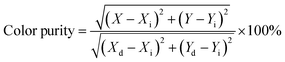
Powder XRD patterns of Tb3+/Eu3+-activated/co-activated LiAl(PO3)4 and LiAl(PO3)4 phosphors doped with Tb3+/Eu3+/M1+ (M = Na, K) are depicted in Fig. 1(a). As observed in this figure, the XRDs of all prepared phosphors are in good agreement with the standard pattern, JCPDS PDF no. #380049. However, some peaks are shifting towards a lower angle [Fig. 1(b)]. The shift in the XRD peaks towards lower angles might be due to change in the ionic radii in host lattice and rare earth ions and alkali ions doped (Tb3+, r = 1.04 Å CN = 8; Eu3+, r = 1.066 Å, CN = 8), (Li+, r = 0.92 Å CN = 6, Na1+, r = 1.18 Å CN = 8; K1+, r = 1.51 Å CN = 8). Moreover, there were no extra impurity peaks, and hence, the samples were prepared in a very good manner.
 |
| | Fig. 1 (a) XRD patterns of Tb3+/Eu3+ activated/co-activated LiAl(PO3)4 phosphors and LiAl(PO3)4 phosphors doped with Tb3+/Eu3+/M1+ (M = Na, K) compared with the standard XRD. (b) Zoomed XRD patterns showing shifting of the diffraction peaks. | |
To validate this statement, Rietveld refinement was performed on the XRD pattern, as shown in Fig. 2. Rietveld refinement was carried out together with their difference profile and Bragg locations utilizing the Fullprof Suite programme to verify this claim.52–54 The visualization requirements were met by the reliability factors along with the parameters Rwp = 15.26, Rp = 7.78, Rexp = 11.15, and χ2 = 2.17. The volume of the unit cell obtained from the Rietveld refinement was 916.439 Å3.
 |
| | Fig. 2 Rietveld refinement of LiAl(PO3)4 phosphor doped with Tb3+ (1 mol%). | |
Fig. 3 depicts the ball and stick and the polyhedral crystal structure orthorhombic with lattice data a = 12.43 Å, b = 8.22 Å, c = 8.91 Å, and α = β = λ = 90.00°. Pbcn space group is the crystallization space for LiAl(PO3)4. Li+ forms deformed LiO4 tetrahedra by bonding with four O2− atoms, which share corners with four comparable PO4 tetrahedra and an edge–edge with an AlO6 octahedron. There are four Li–O bond lengths in total: two shorter (1.92 Å) and two longer (2.07 Å). Al3+ forms AlO6 octahedra by bonding with six O2− atoms, which share corners with six PO4 tetrahedra and an edge–edge with one LiO4 tetrahedra. Al–O bond separations vary and range from 1.89 Å to 1.92 Å. Two different P5+ locations exist. In the first P5+ site, P5+ forms PO4 tetrahedra by bonding with four O2− atoms. These tetrahedra share corners with one AlO6 octahedron, two equivalent LiO4 tetrahedra, and two equivalent PO4 tetrahedra. The octahedral corner-sharing tilt angles are 42°. The P–O bond separations vary and range from 1.48 Å to 1.62 Å. In the second P5+ site, P5+ forms PO4 tetrahedra that share corners with two equivalent AlO6 octahedra and corners with two equivalent PO4 tetrahedra via bonding with four O2− atoms. The octahedral corner-sharing tilt angles range from 42° to 47°. There is a range of P–O bond separations between 1.50 Å and 1.60 Å. There are six incompatible O2− locations. O2− is coupled to two P5+ atoms at the first O2− site in a bent 120° geometry that is deformed. O2− is bound to two P5+ atoms in the second O2− site at an abnormal angle of 120°. One Al3+ and one P5+ atoms are connected by a 150° bent, twisted geometry to O2− at the third O2− site. O2− is bound to one Li+ and one P5+ atom in a bent 150° geometry at the fourth O2− location. O2− is bound to one Al3+ and one P5+ atom in bent 120° distortion geometry at the fifth O2− site. One Li+, one Al3+, and one P5+ atom are joined by O2− in a deformed trigonal planar geometry at the sixth O2− site. The structural parameters for LiAl(PO3)4 phosphor are summarized in Table 1.
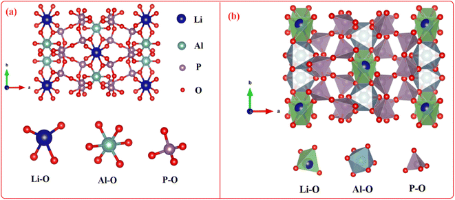 |
| | Fig. 3 The crystal structure of LiAl(PO3)4 material obtained from Rietveld refinement. | |
Table 1 Overview of the structural parameters of the LiAl(PO3)4 material
| |
|
x |
y |
z |
Occ. |
U |
Site |
Sym. |
| 1 |
O1 |
0.2442 |
0.1049 |
0.0804 |
1 |
0.006 |
8d |
1 |
| 2 |
O2 |
0.3951 |
0.4079 |
0.3732 |
1 |
0.006 |
8d |
1 |
| 3 |
O3 |
0.3199 |
0.1413 |
0.4604 |
1 |
0.006 |
8d |
1 |
| 4 |
O4 |
0.1204 |
0.3658 |
0.3773 |
1 |
0.006 |
8d |
1 |
| 5 |
O5 |
0.0623 |
0.1985 |
0.1353 |
1 |
0.006 |
8d |
1 |
| 6 |
O6 |
0.4329 |
0.0286 |
0.1344 |
1 |
0.006 |
8d |
1 |
| 7 |
P1 |
0.13919 |
0.18251 |
0.00584 |
1 |
0.006 |
8d |
1 |
| 8 |
P2 |
0.35134 |
0.03648 |
0.01166 |
1 |
0.006 |
8d |
1 |
| 9 |
Li1 |
0 |
0.0028 |
0.25 |
1 |
0.006 |
4c |
2 |
| 10 |
Al1 |
0 |
0.3676 |
0.25 |
1 |
0.006 |
4c |
2 |
3.2 SEM and EDS analysis
In order to investigate the morphology and elemental mapping in the prepared phosphors, SEM and EDS analysis were performed. SEM micrographs of the prepared phosphors are shown in Fig. 4. As observed in Fig. 4, samples are in the micrometer range with irregular shapes and sizes. The microscopic size of the prepared phosphor makes it a potential phosphor candidate as per the point of view of WLED.53,55,56
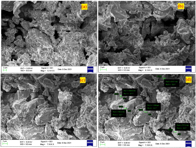 |
| | Fig. 4 SEM micrograph of LiAl(PO3)4phosphors doped with Tb3+/Eu3+/M1+ (M = Na, K). | |
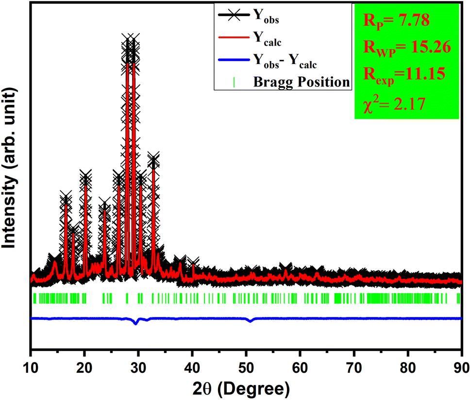
EDS analysis was performed in order to investigate the presence of elements or any other impurities in the prepared phosphor. The EDS analysis of LiAl(PO3)4 phosphors doped with Tb3+/Eu3+/M1+ (M = Na, K) is depicted in Fig. 5. EDS confirmed that all the raw materials used in the synthesis were present in the prepared phosphor, and no other impurities were observed. The insets of Fig. 5(a) and (b) show the wt% distribution of precursors used in the prepared phosphor.
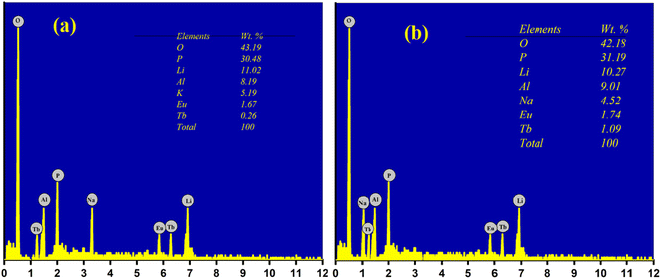 |
| | Fig. 5 EDS analysis of LiAl(PO3)4 phosphors doped with Tb3+/Eu3+/M1+ [M = Na (a), K (b)]. | |
3.3 Photoluminescence investigation
The PL excitation and emission spectra of Tb3+ (1 mol%) activated LiAl(PO3)4 phosphor are depicted in Fig. 6. The excitation spectra of the 544 nm emission of phosphor exhibit a broad excitation band in the UV region centred at 262 nm and characteristic peaks in near UV and blue regions. These characteristic excitation peaks attributed to f–f transitions 7F6 → 5D2, 7F6 → 5L10, and 7F6 → 5D3 are positioned at 345 nm, 365 nm, and 378 nm, respectively.57–59 The PL emission spectra of Tb3+-activated LiAl(PO3)4 triggered by excitation at 378 nm showed one dominant emission peak in the green region positioned at 544 nm. The peak attributed at 544 nm is due to the 5D4 → 7F5 transition.60 It was also observed that the emission intensity increased with Tb3+ ion concentration up to 1 mol%, after which the concentration quenching was observed.
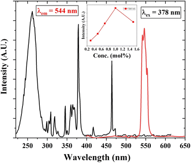 |
| | Fig. 6 PL excitation and emission spectra of Tb3+ (1 mol%) activated LiAl(PO3)4 phosphors (inset: the variation of emission intensity of 544 nm peak with Tb3+ ion concentration). | |
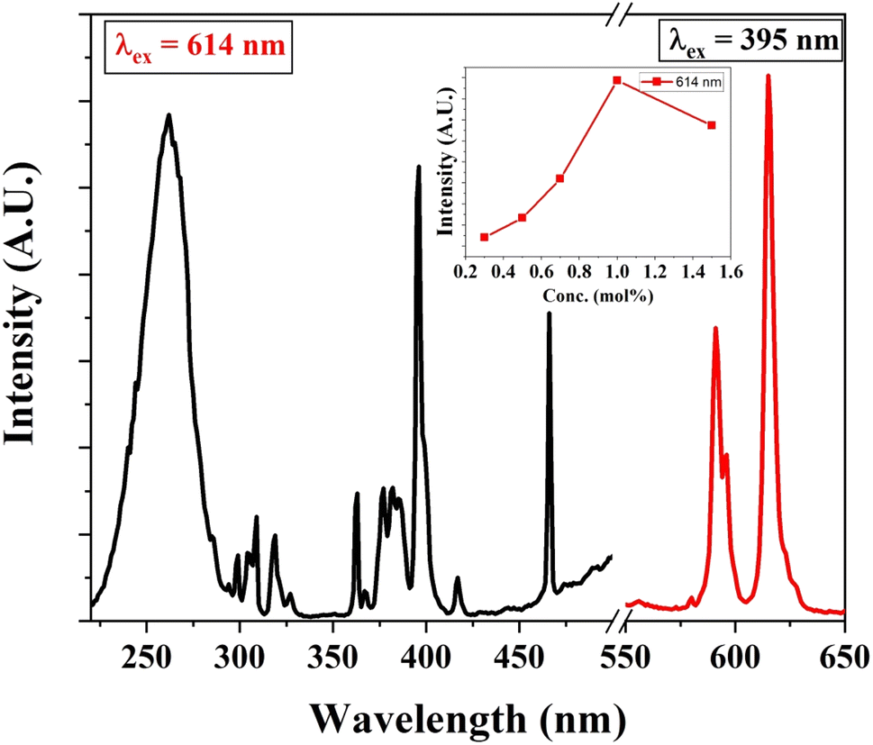
Similarly, Eu3+ ion-activated LiAl(PO3)4 phosphors were also investigated by PL spectroscopy. The PL excitation and emission spectra of the Eu3+ activated LiAl(PO3)4 phosphors are displayed in Fig. 7. The PL excitation spectra monitored at 614 nm exhibited 4 characteristic excitation bands positioned at 261 nm, 395 nm, 465 nm, and 535 nm. The peak observed at 261 nm is due to the O2− → Eu3+ charge transfer band. However, other bands observed in the NUV region (395 nm), blue region (465 nm), and green region (535 nm) are due to 7F0 → 5L6, 7F0 → 5D3 and 7F0 → 5D1 transition, respectively.61,62
 |
| | Fig. 7 PL excitation and emission spectra of Eu3+ (1 mol%) activated LiAl(PO3)4 phosphors (inset: the variation of emission intensity of 544 nm peak with Tb3+ ion concentration). | |
Eu3+-activated LiAl(PO3)4 phosphors after further excitation at 395 nm gave two characteristic emission peaks positioned at 591 nm and 614 nm in the orange and red regions, which are ascribed to 5D0 → 7F1 magnetic dipole transition and 5D0 → 7F2 electric dipole transition of Eu3+ ions, respectively.32,63,64 The peak due to the electric dipole transition is more intense than the magnetic dipole transition, which indicates that the location of the Eu3+ ion is at the non-centrosymmetric site in the host lattice. The variation in the emission intensity of the Eu3+-activated LiAl(PO3)4 phosphors showed a pattern similar to that of Tb3+-activated LiAl(PO3)4 phosphors, which indicated that the doping of rare earth ion occurred at the same site in the host lattices.
The reason behind the concentration quenching effect observed in the PL emission intensity of the rare earth ion-activated LiAl(PO3)4 phosphor is the critical transfer distance (RC), which is the minimum distance between the nearest activator at a critical concentration XC. The critical transfer distance can be calculated using Blasse formula;65–67
| |
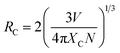 | (1) |
where,
V (=916.439 Å
3) is the volume of the unit cell,
XC = 1 mol%, and
N = 4 number of cationic sites in the unit cell. The value of
RC for both rare earth ion-activated LiAl(PO
3)
4 phosphors was found to be 35.244. If the value of
RC is more than 5, the electric multipolar interaction will be the predominant mechanism causing the concentration quenching event, otherwise, an exchange interaction will be responsible. Because the calculated value of
RC is more than 5 it indicates that the electric multipolar interaction is responsible for the concentration quenching effect in rare earth ion-activated LiAl(PO
3)
4 phosphor.
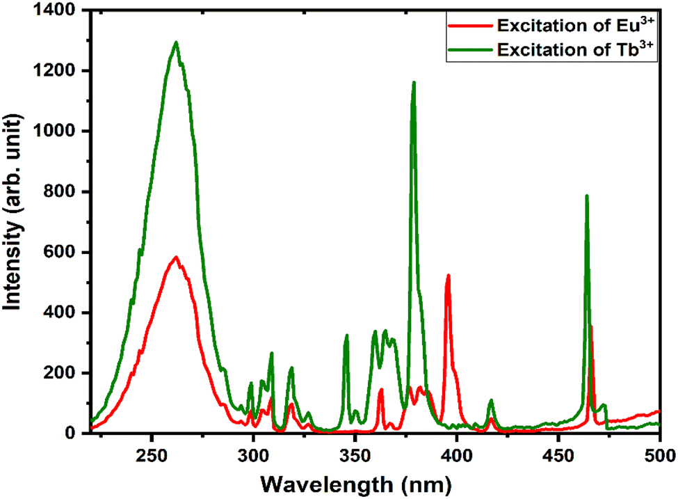
The energy transfer criterion was satisfied by the spectral overlap shown in Fig. 8. The spectral overlapping occurred between the excitation–excitation of Tb3+ and Eu3+ ion-activated LiAl(PO3)4 phosphors. As per the criteria, the excitations of both rare earths overlapped, and it was observed that the excitation of Eu3+ is on the higher wavelength side as compared to the excitation of Tb3+ ions. Therefore, the energy can be transferred from Tb3+ to Eu3+ ions.
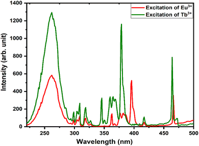 |
| | Fig. 8 Spectral overlap between the excitations of Tb3+ and Eu3+ activated LiAl(PO3)4 phosphors. | |
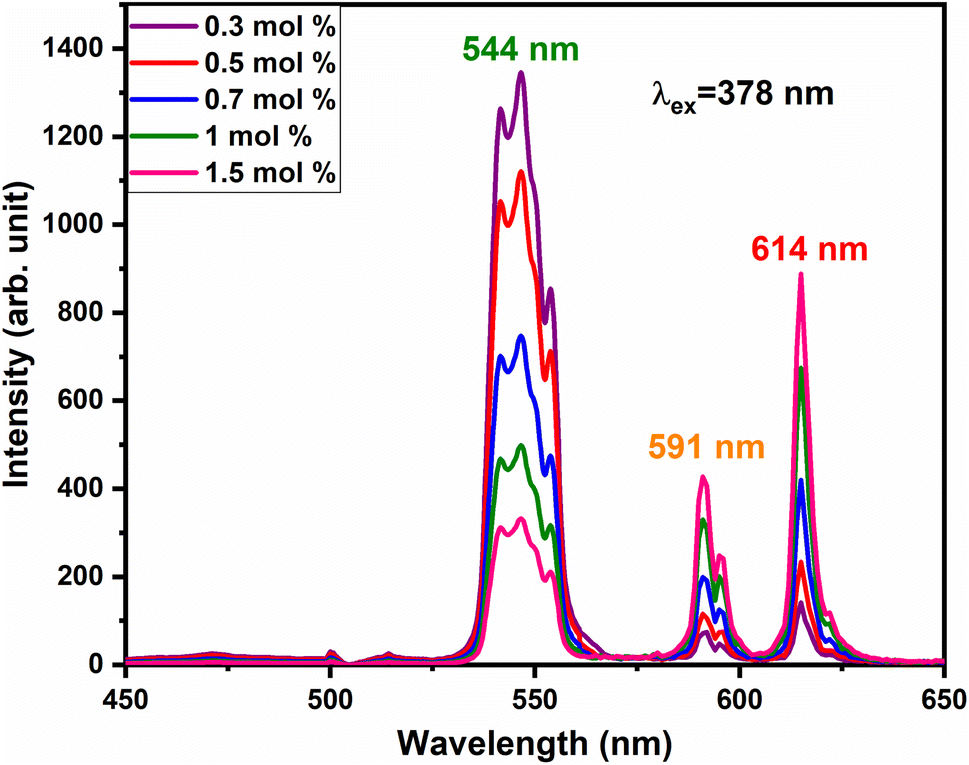
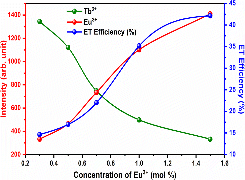
To satisfy the energy transfer criteria, Tb3+, Eu3+ co-activated LiAl(PO3)4 phosphors were prepared by keeping the concentration of Tb3+ ions constant at 1 mol% and Eu3+ concentration varying from 0.3 mol% to 1.5 mol%. The PL emission spectra of this co-activated phosphor triggered at 378 nm excitation are displayed in Fig. 9 and have three characteristic emission peaks centred at 544 nm 591 nm and 614 nm. The peaks attributed in emission spectra are already known for Tb3+ and Eu3+ ions and their transitions are already mentioned in the above section.
 |
| | Fig. 9 PL emission spectra of LiAl(PO3)4:Tb3+ (1 mol%), yEu3+ phosphors at an excitation of 378 nm. | |
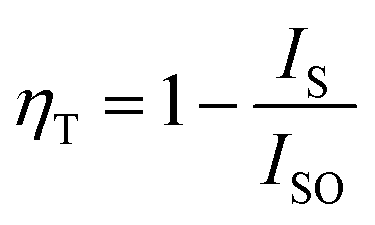
The variation in the intensity of Tb3+ and Eu3+ emission peaks is depicted in Fig. 10. As observed, the intensity of the peak centred at 544 nm (Tb3+ ions) was diminished and peaks centred at 591 nm and 614 nm (Eu3+ ions) increased with the concentration of Eu3+ ions. This shows the energy is transferred from Tb3+ ions to Eu3+ ions. The energy transfer efficiency (ηT) from Tb3+ to Eu3+ can be calculated using the following equation;68
| |
 | (2) |
where
IS and
ISO are the luminescence intensities of Tb
3+ with and without the presence of Eu
3+, respectively. The
ηT from Tb
3+ to Eu
3+ in LiAl(PO
3)
4 phosphors was calculated as a function of the Eu
3+ concentration, displayed in
Fig. 10. The value of
ηT was found to increase gradually with an increase in Eu
3+ content. When the Eu
3+ ion concentration increased to 1.5 mol%, the transfer efficiency increased to 42.13%, indicating an efficient energy transfer from Tb
3+ to Eu
3+. The energy-level diagram of Tb
3+ to Eu
3+ ions showing a possible scheme of energy transfer is displayed in
Fig. 11.
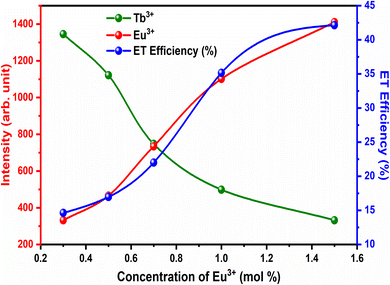 |
| | Fig. 10 ET efficiency and PL emission intensity of Tb3+ and Eu3+ for different concentrations of Eu3+. | |
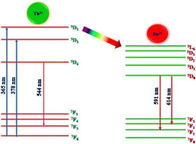 |
| | Fig. 11 Energy-level diagram and energy transfer from Tb3+ to Eu3+. | |
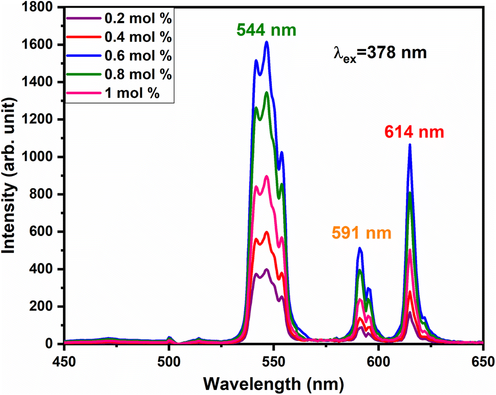
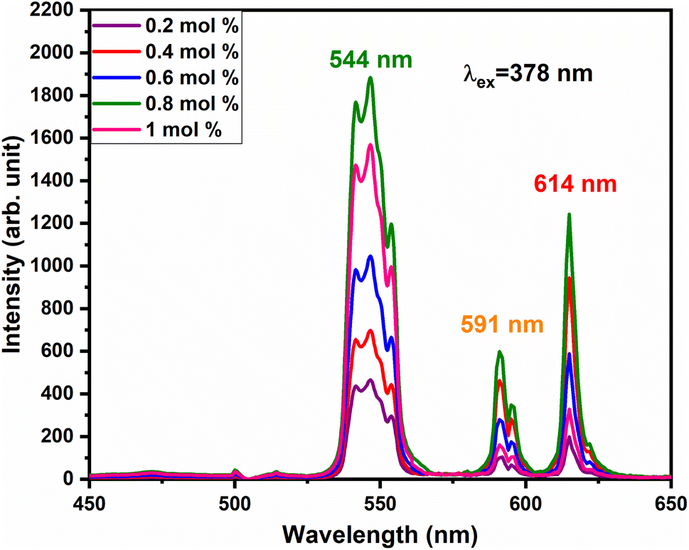
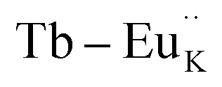
To investigate the charge compensation effect on Tb3+, Eu3+ co-activated LiAl(PO3)4 phosphors, alkali metal ions (Na+ and K+) were introduced as charge compensators. The charge compensation phenomena were observed in the LiAl(PO3)4:Tb3+–Eu3+ host lattice as rare earth ions (Tb3+/Eu3+) doped into the LiAl(PO3)4 phosphor. As per the Kröger–Vink notation,69 the charge compensation is required for  sites.The proximity of charge compensating defects (almost certainly
  vacancies or
  interstitials) gives rise to local deformation of the EuO4 tetragonal and lifts the inversion symmetry and the charge compensation phenomena that occurred here. The PL emission spectra of Tb3+, Eu3+ co-activated LiAl(PO3)4 phosphors doped with Na+ and K+ as charge compensators are shown in Fig. 12 and 13, respectively. The charge compensation of Na+ and K+ ions make a significant impact on the PL intensity of Tb3+, Eu3+ co-activated LiAl(PO3)4 phosphors. The PL intensity was significantly enhanced by 1.2 and 1.4 times that of the Tb3+, Eu3+ co-activated LiAl(PO3)4 phosphors when charge compensators Na+ and K+ were introduced. To manifest the charge compensation effect of alkali metals the optimum intense sample in the co-doped sample was used. The PL emission spectra of 1 mol% Tb3+, 1.5 mol% Eu3+ co-activated LiAl(PO3)4 phosphors displayed in Fig. 12 and 13 by charge compensating Na+ and K+ consisted of different mol% of Na+ and K+ ions, respectively. It was observed that the PL emission intensity enhanced by both the charge compensation and the optimum sample obtained in both charge compensations is 0.6 mol% for Na+ and 0.8 mol% for K+ ions.
 |
| | Fig. 12 PL emission spectra of LiAl(PO3)4:Tb3+(1 mol%), Eu3+(1.5 mol%), zNa+ phosphors at 378 nm excitation. | |
 |
| | Fig. 13 PL emission spectra of LiAl(PO3)4:Tb3+(1 mol%), Eu3+(1.5 mol%), zK+ phosphors at 378 nm excitation. | |
However, the ionic radius of Na+ ions is 1.18 Å and for K+ is 1.51 Å. Comparatively, the ionic radius of the Na+ ion is close to that of the Li+ ion. Thus, the doping of Na+ ion has a weaker strengthening effect on the crystal field and K+ doping has a stronger strengthening effect on the crystal field. Therefore, PL intensity was comparatively enhanced in K+ doping than in Na+ doping.
3.4 Photometric characterization
The PL emission spectra of the produced Tb3+, Eu3+ co-activated LiAl(PO3)4 phosphors were examined using Commission de I Eclairage (CIE) coordinates, as shown in Fig. 14. The useful criteria to gauge the caliber of the luminescence phosphor are the CIE chromaticity coordinates. Table 2 displays the CIE coordinates. The PL emission was shifted towards the red region on charge compensating alkali metal ions into Tb3+, Eu3+ co-activated LiAl(PO3)4 phosphors with efficiency enhancement. This shows the photochromic nature of the prepared phosphors. As shown in Table 2, the produced phosphors' colour purity varied. The provided formula determines colour purity of the phosphor;7,70,71| |
 | (3) |
where, (X, Y), (Xi, Yi), and (Xd, Yd) are color-coordinates of the sample point and CIE equal-energy illuminant, and dominant wavelength of the light source, respectively.
 |
| | Fig. 14 CIE chromaticity diagram of (a) LiAl(PO3)4: 1 mol% Tb3+, 1 mol% Eu3+, (b) LiAl(PO3)4: 1 mol% Tb3+, 1 mol% Eu3+, 0.6 mol% Na+ and (c) LiAl(PO3)4: 1 mol% Tb3+, 1 mol% Eu3+, and 0.8 mol% K+ phosphors. | |
Table 2 Overview of the CIE chromaticity and color purity of LiAl(PO3)4-doped phosphors
| Sr no. |
Sample |
X |
Y |
Xd |
Yd |
Color purity (%) |
| a |
LiAl(PO3)4: 1 mol% Tb3+, 1 mol% Eu3+ |
0.4425 |
0.5294 |
0.3017 |
0.6884 |
54.36 |
| b |
LiAl(PO3)4: 1 mol% Tb3+, 1 mol% Eu3+, 0.6 mol% Na+ |
0.3803 |
0.5824 |
0.3017 |
0.6884 |
69.47 |
| c |
LiAl(PO3)4: 1 mol% Tb3+, 1 mol% Eu3+, 0.8 mol% K+ |
0.3197 |
0.6344 |
0.3017 |
0.6884 |
66.07 |
4. Conclusion
The charge compensation effect and photochromic properties of LiAl(PO3)4: x mol% Tb3+, y mol% Eu3+, z mol% R+ (R = Na, K) doped materials were investigated in this work. LiAl(PO3)4: x mol% Tb3+, y mol% Eu3+, z mol% R+ (R = Na, K) phosphors were prepared by the wet chemical method. The crystal structure of the prepared sample was in the orthorhombic crystal system. The surface morphological behavior and particle size of the prepared phosphor are in the sub-micrometer region, as confirmed by SEM analysis. In the green to red regions, the PL examination of this phosphor revealed four significant emission peaks. In this phosphor, the efficiency of the mechanism of energy transfer from Tb3+ to Eu3+ ions was determined to be 42.13%. Moreover, the charge compensation of the alkali metals can help in improving the intensity of the prepared phosphors by a factor of approximately 1.3 and also shows the photochromic nature of the phosphor. Therefore, all of the indicated results support the studied phosphor material for standing in the race for the development of efficient phosphors for use in color-tunable WLEDs and displays.
Author contributions
Prashant N. Parale – investigation, formal analysis, writing – original draft. Abhijeet R. Kadam – visualization, methodology, investigation, validation, writing – original draft. S. J. Dhoble – supervision, visualization, conceptualization, project administration. K.V. Dabre – supervision, visualization, conceptualization, writing – original draft.
Conflicts of interest
There are no conflicts to declare.
Acknowledgements
This research received no specific grant from any funding agency in the public, commercial, or not-for-profit sectors. The authors are thankful to R. T. M. Nagpur University, Nagpur, for its research facilities and to the authorities at Taywade College, Mahadula-Koradi for constant encouragement.
References
- S. K. Gupta, R. M. Kadam and P. K. Pujari, Coord. Chem. Rev., 2020, 420, 213405 CrossRef CAS.
- B. Shao, J. Huo and H. You, Adv. Opt. Mater., 2019, 7, 1–23 Search PubMed.
- T. Wang, X. Ji, Z. Tao, X. Zhou, Z. Hao, X. Wang, X. Gao, S. Wang and Y. Liu, RSC Adv., 2020, 10, 15573–15578 RSC.
- Q. Wang, G. Chen, Z. Yu, X. Ouyang, J. Tian and M. Yu, ACS Sustain. Chem. Eng., 2018, 6, 13960–13967 CrossRef CAS.
- F. Vanden Bussche, A. M. Kaczmarek, V. Van Speybroeck, P. Van Der Voort and C. V. Stevens, Chem. – Eur. J., 2021, 27, 7214–7230 CrossRef CAS PubMed.
- K. Elzbieciak-Piecka, M. Suta and L. Marciniak, Chem. Eng. J., 2021, 421, 129757 CrossRef CAS.
- A. R. Kadam, G. C. Mishra, A. D. Deshmukh and S. J. Dhoble, J. Lumin., 2021, 229, 117676 CrossRef CAS.
- K. N. Kumar, L. Vijayalakshmi, J. Choi and J. S. Kim, J. Alloys Compd., 2019, 787, 711–719 CrossRef CAS.
- Y. Cong, B. Li, B. Lei, X. Wang, C. Liu, J. Liu and W. Li, J. Lumin., 2008, 128, 105–109 CrossRef CAS.
- J. Yang, J. Zhang, Z. Gao, M. Tao, P. Dang, Y. Wei and G. Li, Inorg. Chem. Front., 2019, 6, 2004–2013 RSC.
- N. Baig, A. R. Kadam, K. Dubey, N. S. Dhoble and S. J. Dhoble, Radiat. Eff. Defects Solids, 2021, 176, 493–507 CrossRef CAS.
- Y. Hua and J. S. Yu, J. Alloys Compd., 2019, 783, 969–976 CrossRef CAS.
- N. Baig, A. R. Kadam, K. Dubey, N. S. Dhoble and S. J. Dhoble, Radiat. Eff. Defects Solids, 2021, 176, 493–507 CrossRef CAS.
- Y. Wu, J. Peng, D. Rutstrom, M. Koschan, C. Foster and C. L. Melcher, ACS Appl. Mater. Interfaces, 2019, 11, 8194–8201 CrossRef CAS PubMed.
- L. Stand, M. Zhuravleva, J. Johnson, M. Koschan, Y. Wu, S. Donnald, K. Vaigneur, E. Lukosi and C. L. Melcher, J. Cryst. Growth, 2018, 483, 301–307 CrossRef CAS.
- S. V. Kuznetsov, A. S. Nizamutdinov, M. N. Mayakova, V. V. Voronov, E. I. Madirov, A. R. Khadiev, D. A. Spassky, I. A. Kamenskikh, A. D. Yapryntsev, V. K. Ivanov, M. A. Marisov, V. V. Semashko and P. P. Fedorov, Nanosyst.: Phys., Chem., Math., 2019, 10, 190–198 CAS.
- P. W. Metz, D. T. Marzahl, A. Majid, C. Kränkel and G. Huber, Laser Photonics Rev., 2016, 10, 335–344 CrossRef CAS.
- M. Mozetič, A. Vesel, G. Primc, C. Eisenmenger-Sittner, J. Bauer, A. Eder, G. H. S. Schmid, D. N. Ruzic, Z. Ahmed, D. Barker, K. O. Douglass, S. Eckel, J. A. Fedchak, J. Hendricks, N. Klimov, J. Ricker, J. Scherschligt, J. Stone, G. Strouse, I. Capan, M. Buljan, S. Milošević, C. Teichert, S. R. Cohen, A. G. Silva, M. Lehocky, P. Humpoliček, C. Rodriguez, J. Hernandez-Montelongo, D. Mercier, M. Manso-Silván, G. Ceccone, A. Galtayries, K. Stana-Kleinschek, I. Petrov, J. E. Greene, J. Avila, C. Y. Chen, B. Caja-Munoz, H. Yi, A. Boury, S. Lorcy, M. C. Asensio, J. Bredin, T. Gans, D. O'Connell, J. Brendin, F. Reniers, A. Vincze, M. Anderle and L. Montelius, Thin Solid Films, 2018, 660, 120–160 CrossRef.
- T. Sun, K. Tang, H. Cui, H. Zhu and H. Fan, J. Lumin., 2019, 205, 568–571 CrossRef CAS.
- V. S. Kortov, Radiat. Meas., 2010, 45, 512–515 CrossRef CAS.
- M. Janani, P. Srikrishnarka, S. V. Nair and A. S. Nair, J. Mater. Chem. A, 2015, 3, 17914–17938 RSC.
- S. C. A. Sousa, J. C. Cardoso and O. C. Monteiro, J. Photochem. Photobiol., A, 2019, 378, 9–16 CrossRef CAS.
- M. Sepasian, C. Mares and W. Balachandran, Multibiometric security in wireless communication systems, School of Engineering and Design, Brunei University, 2010, pp. 150–158 Search PubMed.
- P. Dewangan, D. P. Bisen, N. Brahme, S. Sharma, R. K. Tamrakar, I. P. Sahu and K. Upadhyay, J. Alloys Compd., 2020, 816, 152590 CrossRef CAS.
- S. R. Lim, D. Kang, O. A. Ogunseitan and J. M. Schoenung, Environ. Sci. Technol., 2013, 47, 1040–1047 CrossRef CAS PubMed.
- A. R. Kadam and S. J. Dhoble, J. Alloys Compd., 2021, 884, 161138 CrossRef CAS.
- K. Mondal and J. Manam, J. Lumin., 2018, 195, 259–270 CrossRef CAS.
- V. Singh, A. R. Kadam and S. J. Dhoble, Optik, 2021, 243, 167437 CrossRef CAS.
- Q. Dan and T. Wanjun, Ceram. Int., 2016, 42, 1538–1544 CrossRef CAS.
- Y. Wang, L. Xie and H. Zhang, J. Appl. Phys., 2009, 105, 3–7 Search PubMed.
- S. G. M. Mushtaque, A. R. Kadam and S. J. Dhoble, J. Mol. Struct., 2023, 1274, 134510 CrossRef CAS.
- A. R. Kadam and S. J. Dhoble, Luminescence, 2019, 34, 846–853 CrossRef CAS PubMed.
- A. R. Kadam, G. C. Mishra and S. J. Dhoble, Ceram. Int., 2019, 1–24 Search PubMed.
- H. Lin, S. Zhou, H. Teng, Y. Li, W. Li, X. Hou and T. Jia, J. Appl. Phys., 2010, 107, 1–5 Search PubMed.
- Z. Cai, C. Wei, B. Sun, H. Wei, Z. Liu, Z. Bian and C. Huang, Inorg. Chem. Front., 2021, 8, 41–47 RSC.
- F. Wu, R. Tseng, C. Hu and C. Wang, J. Power Sources, 2005, 144, 302–309 CrossRef CAS.
- K. N. Shinde, R. Singh and S. J. Dhoble, J. Lumin., 2014, 146, 91–96 CrossRef CAS.
- Y. K. Kim, M. Lee, H. S. Yang, M. G. Ha and K. S. Hong, Curr. Appl. Phys., 2016, 16, 357–360 CrossRef.
- J. Liang, L. Sun, G. Annadurai, B. Devakumar, S. Wang, Q. Sun, J. Qiao, H. Guo, B. Li and X. Huang, RSC Adv., 2018, 8, 32111–32118 RSC.
- H. Lai, J. Zhang, D. Hou, H. Guan and X. Ye, Ceram. Int., 2018, 44, 15072–15078 CrossRef CAS.
- S. K. Gupta, K. S. Prasad, N. Pathak and R. M. Kadam, J. Mol. Struct., 2020, 1221, 128776 CrossRef CAS.
- S. K. Gupta, M. Abdou, P. S. Ghosh, J. P. Zuniga and Y. Mao, ACS Omega, 2019, 4, 2779–2791 CrossRef CAS PubMed.
- M. Xia, S. Gu, C. Zhou, L. Liu, Y. Zhong, Y. Zhang and Z. Zhou, RSC Adv., 2019, 9, 9244–9252 RSC.
- X. Kang, C. Jia, H. Wang, Y. Xiao and W. Lü, Mater. Chem. Phys., 2020, 240, 122239 CrossRef CAS.
- A. Maurya, A. Bahadur, A. Dwivedi, A. K. Choudhary, T. P. Yadav, P. K. Vishwakarma and S. B. Rai, J. Phys. Chem. Solids, 2018, 119, 228–237 CrossRef CAS.
- G. B. Nair, H. C. Swart and S. J. Dhoble, Prog. Mater. Sci., 2020, 109, 100622 CrossRef CAS.
- R. S. Yadav, M. Rai, S. B. Rai and S. J. Dhoble, Prog. Solid State Chem., 2020, 57, 100267 CrossRef CAS.
- P. Sobierajska, R. Pazik, K. Zawisza, G. Renaudin, J. M. Nedelec and R. J. Wiglusz, CrystEngComm, 2016, 18, 3447–3455 RSC.
- R. Cao, H. Xiao, F. Zhang, X. Cheng, L. Su, F. Xiao, Z. Luo and T. Chen, J. Mater. Sci.: Mater. Electron., 2019, 30, 2327–2333 CrossRef CAS.
- Z. Yang, L. Yang, Y. Pu and D. chuan Zhu, Opt. Mater., 2021, 114, 110981 CrossRef CAS.
- K. Dubey, A. R. Kadam, N. Baig, N. S. Dhoble and S. J. Dhoble, Radiat. Eff. Defects Solids, 2021, 176, 431–440 CrossRef CAS.
- A. R. Kadam, C. Mishra Girish, S. J. Dhoble and R. S. Yadav, Ceram. Int., 2020, 46, 3264–3274 CrossRef CAS.
- A. R. Kadam, R. B. Kamble, M. Joshi, A. D. Deshmukh and S. J. Dhoble, New J. Chem., 2022, 334–344 RSC.
- A. R. Kadam, G. C. Mishra, M. Michalska-Domanska and S. J. Dhoble, J. Mol. Struct., 2020, 129505 Search PubMed.
- V. Singh, A. R. Kadam and S. J. Dhoble, Optik, 2021, 243, 167437 CrossRef CAS.
- A. R. Bansod, A. R. Kadam, P. S. Bokare and S. J. Dhoble, Luminescence, 2022, 37(8), 1352–1360 CrossRef CAS PubMed.
- H. Zhang, X. Zhang, Z. Cheng, Y. Xu, J. Yang and F. Meng, Ceram. Int., 2018, 44, 2547–2551 CrossRef CAS.
- X. Xiao, S. Xu and B. Yan, J. Alloys Compd., 2007, 429, 255–259 CrossRef CAS.
- S. A. Khan, N. Z. Khan, W. W. Ji, L. Ali, H. Abadikhah, L. Hao, X. Xu, S. Agathopoulos, Q. Khan and L. Zhu, Dyes Pigm., 2019, 160, 675–682 CrossRef CAS.
- T. Zhou, L. Mei, Y. Zhang, L. Liao, H. Liu and Q. Guo, Opt Laser. Technol., 2019, 111, 191–195 CrossRef CAS.
- A. R. Kadam, R. L. Kohale, G. C. Mishra and S. J. Dhoble, New J. Chem., 2021, 45, 7285–7307 RSC.
- X. Min, Y. Sun, L. Kong, M. Guan, M. Fang, Y. Liu, X. Wu and Z. Huang, Dyes Pigm., 2018, 157, 47–54 CrossRef CAS.
- A. Duragkar, N. S. Dhoble, A. R. Kadam and S. J. Dhoble, Enhanced photoluminescence in RE (Eu3+, Ce3+ and Sm3+)-activated Ca10(PO4)F2 phosphors by double or triple ionized mineral doping: a comparative study, Luminescence, 2021, 36(3), 606–620 CrossRef CAS PubMed.
- R. G. Deshmukh, A. R. Kadam and S. J. Dhoble, J. Mol. Struct., 2022, 1257, 132603 CrossRef CAS.
- A. R. Bansod, A. R. Kadam, P. S. Bokare and S. J. Dhoble, Luminescence, 2022, 1352–1360 CrossRef CAS PubMed.
- V. Singh, A. R. Kadam, S. J. Dhoble and H. Jeong, Optik, 2021, 243, 167396 CrossRef CAS.
- V. Singh, A. R. Kadam, S. J. Dhoble and H. Jeong, Optik, 2021, 243, 167327 CrossRef CAS.
- X. Fu, L. Fang, S. Niu and H. Zhang, J. Lumin., 2013, 142, 163–166 CrossRef CAS.
- T. Senden, R. G. Geitenbeek and A. Meijerink, Materials, 2017, 10(11), 1322–1336 CrossRef PubMed.
- A. R. Kadam, S. B. Dhoble, G. C. Mishra, A. D. Deshmukh and S. J. Dhoble, J. Mol. Struct., 2021, 1233, 130150 CrossRef CAS.
- T. S. Dhapodkar, A. R. Kadam, N. Brahme and S. J. Dhoble, Mater. Today Chem., 2022, 24, 100938 CrossRef CAS.
|
| This journal is © The Royal Society of Chemistry 2023 |
Click here to see how this site uses Cookies. View our privacy policy here. 
 Open Access Article
 This Open Access Article is licensed under a
  *c,
S. J. Dhoblea and
K. V. Dabre
*c,
S. J. Dhoblea and
K. V. Dabre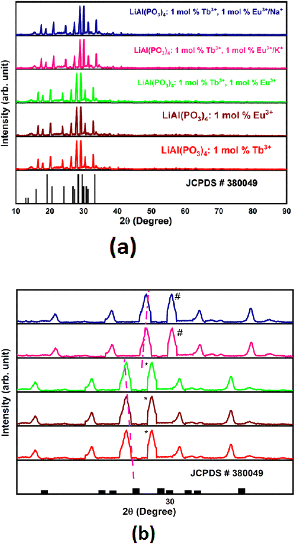


 sites.The proximity of charge compensating defects (almost certainly
 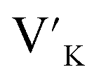 vacancies or
  interstitials) gives rise to local deformation of the EuO4 tetragonal and lifts the inversion symmetry and the charge compensation phenomena that occurred here. The PL emission spectra of Tb3+, Eu3+ co-activated LiAl(PO3)4 phosphors doped with Na+ and K+ as charge compensators are shown in Fig. 12 and 13, respectively. The charge compensation of Na+ and K+ ions make a significant impact on the PL intensity of Tb3+, Eu3+ co-activated LiAl(PO3)4 phosphors. The PL intensity was significantly enhanced by 1.2 and 1.4 times that of the Tb3+, Eu3+ co-activated LiAl(PO3)4 phosphors when charge compensators Na+ and K+ were introduced. To manifest the charge compensation effect of alkali metals the optimum intense sample in the co-doped sample was used. The PL emission spectra of 1 mol% Tb3+, 1.5 mol% Eu3+ co-activated LiAl(PO3)4 phosphors displayed in Fig. 12 and 13 by charge compensating Na+ and K+ consisted of different mol% of Na+ and K+ ions, respectively. It was observed that the PL emission intensity enhanced by both the charge compensation and the optimum sample obtained in both charge compensations is 0.6 mol% for Na+ and 0.8 mol% for K+ ions.