 Open Access Article
Morphologies, mechanical and in vitro behaviors of DLP-based 3D printed HA scaffolds with different structural configurations
Ke Liuab,
Qing Zhouc,
Xueqin Zhangc,
Lili Maa,
Baohua Xu*a and
Rujie He *c
*c
aCenter of Stomatology, China-Japan Friendship Hospital, Beijing, 100029, China. E-mail: drxubaohua@163.com
bGraduate School of Peking Union Medical College, Chinese Academy of Medical Sciences and Peking Union Medical College, Beijing 100029, China
cBeijing Key Laboratory of Lightweight Multi-functional Composite Materials and Structure, Beijing Institute of Technology, Beijing 100081, China. E-mail: herujie@bit.edu.cn
First published on 11th July 2023
Abstract
In the field of bone engineering, porous ceramic scaffolds are in great demand for repairing bone defects. In this study, hydroxyapatite (HA) ceramic scaffolds with three different structural configurations, including the body-centered cubic (BCC), the face-centered cubic (FCC), and the triply periodic minimal surface (TPMS), were fabricated through digital light processing (DLP) based 3D printing technologies. The effects of the structural configurations on the morphologies and mechanical properties of the DLP-based 3D printed HA scaffolds were characterized. Furthermore, in vitro evaluations, including in vitro cytocompatibility, bone alkaline phosphatase (ALP) activity assay, and protein expression, were conducted to assess HA scaffold behavior. Finally, we evaluated the effects of structural configurations from these aspects and selected the most suitable structure of HA scaffold for bone repair.
1. Introduction
The restoration of bone defects is currently an important clinical challenge. Stimulating the biological activity of bone regeneration and structural features that can be perfectly adapted to the patient's defect are key to the success of bone repair alternatives.1 Biologically inert ceramics such as zirconia,2,3 bioactive ceramics4–6 such as hydroxyapatite (HA),7–9 and metallic materials such as titanium (Ti)10,11 are currently commonly used in clinical and research applications for bone repair. Among them, bioactive ceramics represented by HA have better osteoconductivity, similar mechanical properties to natural bone, and are the most important and widely used materials in bone repair.12 In particular, HA is biocompatible, safe, and non-toxic and conducts bone growth in the body.13,14 New bone can grow from the HA implant to the original bone by climbing along the implant surface or through the internal penetrating pores.15,16Besides, pore characteristics are important parameters of bioengineered scaffolds.17,18 The pore shape affects whether cells can grow and expand.19,20 Also, pore characteristics affect the mechanical properties of the scaffold, which in turn affects the ability of the scaffold to support the bone defect.21,22 Earlier, the effect of pore characteristics of calcium phosphate-based materials on bone regeneration was analyzed by Bose et al.13,16,23 In 2012, Bose et al.23 investigated the effect of porosity and pore size on the mechanical strength of bone cell–material interactions in vitro and osteogenic processes in vivo. They designed three scaffolds with pore sizes of 500, 750, and 1000 μm and showed that cell density increased with decreasing interconnected pore size, while in vivo, large pores favored osteogenesis and vascularization. Recently, tremendous efforts have been made to porous HA scaffolds.7,24,25
On the one hand, due to the high complexity of the porous HA scaffolds, the traditional processing technologies are difficult to achieve accurate processing. In 2001, Hutmacher et al.26 suggested that implants need to support cell attachment, proliferation, and maintenance of their differentiation. The structure needs to match the soft tissue of the neoplastic tissue. Usually, porous HA scaffolds are mainly realized by the 3D printing process.27 Till now, 3D-printed HA ceramic and its structures have received greater attention due to their better bioactivity and designable structure.28–30 Common 3D printing technologies, such as selective laser sintering (SLS), selective laser melting (SLM), laminated object manufacturing (LOM), binder jetting (BJ), vat photopolymerization (VP), fused deposition modeling (FDM), direct ink writing (DIW),22,31 have been adopted to produce porous ceramic scaffolds. Halloran et al.32 investigated light-cured ceramic pastes. They obtained initial stable ceramic curing pastes and successfully prepared casting molds. They developed the properties of a simple resin consisting of aluminum powder suspended in hexanediol diacrylate (HDDA) and explored the depth of cure as a function of dose for a high-density laser in SLA, which set the stage for the development of a stable light-curing technology. Apart from this, Feng et al.33 developed digital light processing (DLP)-based 3D printing to prepare HA structures. They discussed the ink conditions, sintering parameters, mechanical properties, and cellular properties of the as-printed HA in detail. Zhang et al.34 also prepared HA structures with high resolution and micro–nano inner porosity by DLP technology. The HA scaffolds exhibited good pore characteristics, compressive strength, and biological properties. To achieve a high cell attachment during implant, the HA scaffolds need to have high porosity. However, the reported porosity was usually below 50 vol%, how to achieve the 3D printing of HA scaffolds with high porosity (normally above 50 vol%) is a challenge.
On the other hand, the structural configuration of the HA scaffolds also has significant effects on their behaviors. Recently, various kinds of structures have been applied to porous HA scaffolds. Especially, classic lattice structures with regular apertures, including the body-centered cubic (BCC), the face-centered cubic (FCC), and so on, have drawn great attention, especially in metallic materials. Zhang et al.35 designed porous metallic biomaterials and simulated the topology, mechanics, and mass transport properties of human bones, and the results showed that the scaffolds could mimic the biological role of bones while maintaining mechanical properties. To simulate the properties of natural bone due to its inhomogeneous pore size distribution, metal materials with graded pore gradient lattice structure were designed by Mahmoud et al.36 Parisien et al.37 explored the mechanical properties and bone stimulation applications of FCC and BCC structures in bone engineering, demonstrated that the dotted structures have bone growth stimulating effects, demonstrating the potential for application in bone scaffolding applications. Besides, the triply periodic minimal surface (TPMS), which is a surface with the minimum area and zero average curvature that satisfy specific constraints and are arranged periodically in space, has also intensively received much attention because of its smooth surface and bionic nature. The TPMS structures made of titanium alloy were prepared by Bobbert et al.38 using SLM. This structure simulates the topological, mechanical, and mass transport properties of bone and meets the needs of porous biomaterials. Noroozi et al.39 designed and fabricated a three-cycle minimal surface (TPMSs) bio-scaffold based on 3D printed poly-(lactic acid)-based composite alginate. This novel scaffold improves the low mechanical properties of alginate hydrogels and also provides a scaffold with a suitable pore size that can be used for bone regeneration applications. Till now, there have been few reports about the 3D printed HA scaffolds with TPMS structure yet. Wang et al.40 investigated the cubic structure of metallic materials, the magnitude of mechanical row properties of TPMS structure, and the comparison of cytotoxicity. Zhang et al.41 also developed high-strength HA scaffolds with TPMS for load-bearing bone regeneration. However, most importantly, the effects of different structural configurations of HA scaffolds have not been clearly understood. Therefore, figuring out the intrinsic relationship between the structural configuration and the behaviors of 3D printed HA scaffold is another key issue to solve.
Herein, porous HA scaffolds with different structural configurations, including BCC, FCC, and TPMS, were designed with high porosity of up to 60 vol% and digital light processing (DLP) based 3D printed. Especially, to evaluate the structural configurations in terms of morphologies, mechanical properties, and in vitro biological properties of 3D printed HA scaffolds, we performed the characterization of morphologies, compression properties, in vitro cell proliferation, ALP expression activity, and osteogenic protein expression on the scaffolds. We evaluated the effects of structural configurations from these aspects and selected the most suitable structure of HA scaffold for bone repair.
2. Materials and methods
The study on the mechanical and in vitro behaviors of 3D-printed HA scaffolds with three different structural configurations consisted of five steps: (1) design, (2) 3D printing, (3) morphological observation, (4) mechanical characterization, and (5) in vitro evaluation, as illustrated in Fig. 1.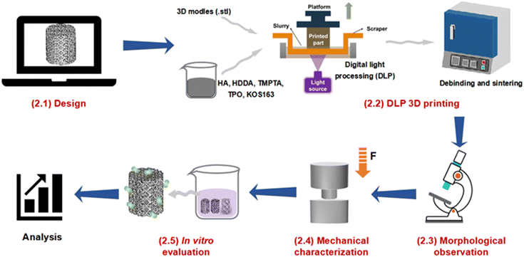 | ||
| Fig. 1 Schematic diagram of the study on morphologies, mechanical and in vitro behaviors of DLP 3D printed HA scaffolds. | ||
2.1 Design
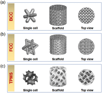
Herein, HA scaffolds with three different structural configurations, including the body-centered cubic (BCC), the face-centered cubic (FCC), and the gyroid (which was one typical type of TPMS), were designed, as shown in Fig. 2. The relative density of the three HA scaffolds was kept at 40 vol%, that was to say, the porosity of the HA scaffolds was set at 60 vol%. The diameter (Φ) and the height (H) of all the HA scaffolds were designed as 8 mm and 8 mm, respectively. The 3D models for the BCC, FCC, and TPMS scaffolds were exported as.stl files for the following 3D printing. For simplicity, in this study, the as-obtained HA scaffold with the structural configuration of BCC, FCC, and TPMS was named BCC, FCC, and TPMS, respectively. Previous report41 showed that the porosity of gyroid TPMS structures ranged from about 55% to 75%, which were higher than this work.2.2 DLP-based 3D printing
Commercial hydroxyapatite powders (HA, average diameter 12 μm, Nanjing Duly Biotech Co., Ltd, China) were used as raw materials. The light-curing resins used in this study were 1,6-hexanediol diacrylate (HDDA, Sinopharm Chemical Reagent Co., Ltd, China) and trimethylolpropane triacrylate (TMPTA, Sinopharm Chemical Reagent Co., Ltd, China). Free radical photoinitiator diphenyl(2,4,6-trimethyl-benzoyl) phosphine oxide (TPO, Sinopharm Chemical Reagent Co., Ltd, China) was used as a photoinitiator. Solsperse KOS163 (Guangzhou Qian'an Chemical Co., Ltd, China) was used as dispersant.Digital light processing (DLP) based 3D printing of HA scaffolds was subsequently conducted in the order of slurry preparation, 3D printing, and debinding and sintering, which was reported in our previous works.7,33
![[thin space (1/6-em)]](https://www.rsc.org/images/entities/char_2009.gif) :
:![[thin space (1/6-em)]](https://www.rsc.org/images/entities/char_2009.gif) 1. Then the HA powders were weighed according to the solid loading (30 vol%). After that, the TPO photoinitiator was added to the slurry and continued milling for 2 h, and the dosage of the TPO was 2 wt% of the solid. The doping content of the Solsperse KOS163 dispersant was set as 5% of the addition of HDDA, TMPTA, and HA weight. Finally, the mixture was turned into the ball mill and stirred for 24 h to make a uniform slurry.
1. Then the HA powders were weighed according to the solid loading (30 vol%). After that, the TPO photoinitiator was added to the slurry and continued milling for 2 h, and the dosage of the TPO was 2 wt% of the solid. The doping content of the Solsperse KOS163 dispersant was set as 5% of the addition of HDDA, TMPTA, and HA weight. Finally, the mixture was turned into the ball mill and stirred for 24 h to make a uniform slurry.2.3 Morphological observation
It is known that the geometries of ceramic scaffolds will shrink to a certain extent after debinding and sintering. In this study, the shrinkage of the HA scaffold in the X/Y direction and Z direction were tested, respectively. The diameter Φ1 and height H1 of the green body were first recorded by a 211–101 digital micrometer (Anyi Instrument Co., Ltd, China), and the diameter Φ2 and height H2 of the sintered body was measured in the same way, the shrinkage was calculated from the ratio of the size of the green body to that of the sintered body, as follows,| Shrinkage in X/Y direction: α = (Φ1 − Φ2)/Φ1 × 100% | (1) |
| Shrinkage in Z direction: β = (H1 − H2)/H1 × 100% | (2) |
All the tests were repeated 5 times to obtain an average value for each scaffold.
The HA scaffolds' microscopic morphologies were observed using a scanning electron microscope (SEM, JSM-7500F, JEOL, Japan), and the HA scaffolds were pre-processed by sputter-coated with gold.
2.4 Mechanical characterizations
The compressive strength of the HA scaffolds was measured with a crosshead speed of 0.05 mm min−1 at room temperature by a universal mechanical testing machine (Instron Legend 2367 testing system, USA). At least 5 specimens were measured to achieve an average value for each condition. The stress–strain curves were recorded, and the compressive strength (σ) was calculated as F/A, where F was the maximum load recorded during testing and A was the cross-sectional area of the scaffold. Test results are expressed as mean ± standard variance.2.5 In vitro evaluation
The survival of stem cells on the scaffold was observed at 3 days of culture using the calcein-AM/PI live/dead cell double-staining kit (YEASEN, 40747ES76). Live cells (yellow-green fluorescence), as well as dead cells (red fluorescence), were detected simultaneously under a fluorescence microscope (Leica, TCS SP8) using a 490 ± 10 nm excitation filter.
2.6 Statistical analysis
All experimental results of the test were expressed as mean plus or minus standard deviation (x ± s), and the chi-square test, one-way analysis of variance (one-way ANOVA), and two-by-two comparison between sample means (q test) were performed using GraphPad Prism 9 statistical software. Statistical significance was set at a limit of P < 0.05. P-values are displayed in the graphs. The null hypothesis that there is an association between the two is taken.3. Results and discussion
3.1 Morphologies
Table 1 lists the shrinkage of DLP 3D-printed HA scaffolds after debinding and sintering. Compared with designed CAD models, all DLP 3D printed HA scaffolds with the structural configuration of BCC, FCC, and TPMS showed obvious dimensional shrinkage both in the X/Y direction and in the Z direction. The shrinkage of BCC, FCC, and TPMS in the X/Y direction was 29.30 ± 0.07%, 29.93 ± 0.34, and 30.04 ± 0.23%, respectively. And the shrinkage of BCC, FCC, and TPMS in the Z direction was 33.03 ± 0.76%, 32.88 ± 1.05%, and 32.65 ± 0.86%, respectively. The average diameter of the BCC structure after sintering was 6.29 ± 0.11 mm and the height was 5.90 ± 0.30 mm. The diameter of the FCC after sintering was 5.70 ± 0.04 mm and the height was 5.61 ± 0.03 mm. The diameter of the TPMS after sintering was 6.35 ± 0.05 mm and the height was 6.01 ± 0.05 mm. Interestingly, the values of shrinkage were similar for different structures. Accurate shrinkage is essential for the accurate 3D printing of HA scaffolds. To produce a HA scaffold with high precision, it was very necessary to enlarge the 3D model considering the shrinkage when designing.| Structural configuration | Shrinkage (%) | |
|---|---|---|
| In X/Y direction | In Z direction | |
| BCC | 29.30 ± 0.07 | 33.3 ± 0.76 |
| FCC | 29.93 ± 0.34 | 32.88 ± 1.05 |
| TPMS | 30.04 ± 0.23 | 32.65 ± 0.86 |
The macro and microstructures of HA scaffolds with different structural configurations are shown in Fig. 3. It was found that all HA scaffolds had outstanding accuracy and surface quality. As shown in Fig. 3a1–a3, typical layer-by-layer characteristics were observed for BCC, owing to the 3D printing processing procedure, which has also been reported in our previous studies.42,43 Similar microstructural characteristics were also found for both FCC and TPMS (as shown in Fig. 3b1–b3, and c1–c3). On the one hand, as shown in Fig. 3a2, a3, b2 and b3, the pore size of the BCC and FCC was about 300–400 μm at a porosity of 60%. Whereas the pore size of TPMS was not able to see clearly. TPMS prepared by 3D printing has interconnected pores and regular boundaries (as shown in Fig. 3c2 and c3). Especially, TPMS is generally difficult to fabricate with conventional machining processes because of their periodic characteristic surfaces. From this study, DLP-based 3D printing can produce an HA scaffold with a TPMS structure. On the other hand, however, some residual cracks were existing among the HA scaffolds, which would mainly deteriorate their mechanical properties. According to the SEM images, BCC had the most cracks, which might be due to the rapid overflow of gases generated by the sintering of the internal resin due to too rapid a cooling down during the sintering process, which leads to the expansion of cracks. How to reduce or eliminate manufacturing cracks might be one of the most mainly focused topics in future research.
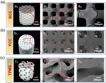 | ||
| Fig. 3 Macro and microstructures of three HA scaffolds: (a) BCC, (b) FCC, and (c) TPMS. Footnote 1 means photograph; footnotes 2 and 3 represent enlarged SEM images. | ||
3.2 Compressive strength
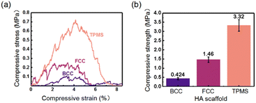
The compressive strength of three HA scaffolds needs to be characterized to ensure adequate support during implantation. Fig. 4a and b shows the strain–stress and maximum yield strength of HA scaffolds under compressive loading, respectively. For all HA scaffolds, their stress–strain curves under compression presented “zigzag” trends, as given in Fig. 4a. These “zigzag” jagged ripples correspond to the failure and fragmentation of the joints inside the HA scaffolds, which was similar to the reports of other 3D printed ceramics under compressive loading.42,43 Besides, the peaks of the compressive stress of these HA scaffolds had the following order: TPMS > FCC > BCC. In this study, the peak of the compressive stress was nominated as the maximum yield compressive strength of HA scaffolds. As shown in Fig. 4b, the compressive strengths of BCC, FCC, and TPMS were 0.42 ± 0.06 MPa, 1.46 ± 0.15 MPa, and 3.32 ± 0.32 MPa, respectively. As found, TPMS exhibited the highest compressive strength and the best mechanical behavior compared to BCC and FCC under the same porosity. That might be attributed to TPMS being composed of curved surfaces with 0 curvature. It should be noted that the strength achieved in this work was still relatively low. Zhang et al.41 got gyroid TPMS structures with high strength ranging from about 3–15 MPa. How to enhance the strength of HA scaffolds with TPMS structures is still a big challenge in our future work. According to the previously reported studies,44 that pore shape was critical in the determination of the mechanical stimuli and mechanical function of the scaffolds.45 And TPMS has a unique spiral structure, which results in a more uniform stress distribution when subjected to stress and avoids the stress concentration effect, thereby providing superior mechanical properties.46,47 However, BCC and FCC are geometric point structures generated by Boolean operations.48 These models have nonuniform over connections at the geometric units with sharp turns or sharp corners and thus are highly susceptible to stress concentrations at the connections when the structure is stressed, resulting in premature failure in service. Most importantly, the compressive strength of produced HA scaffolds barely met the strength requirements of the clinical application.49,50 Among these three HA scaffolds, TPMS seemed to have the most promising clinical application for bone regeneration. Below, the in vitro behaviors of these HA scaffolds with different structural configurations were further investigated to assess the optimal structure type.3.3 Cellular compatibility
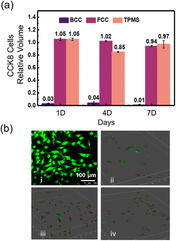
Detection of cell viability on three HA scaffolds was conducted by CCK-8 cell proliferation assay kit. The proliferation of BMSCs cells after 1, 4, and 7 days of culture on the HA scaffolds of the three structures is shown in Fig. 5a. It was found that both FCC and TPMS scaffolds supported the proliferation of BMSCs cells as detected by CCK-8 proliferation assay, the results did not show significant differences compared with the blank group. However, unfortunately, the BCC structure did not support BMSCs cell proliferation and exhibited an inflammatory response and poor cytocompatibility, which might be due to the contamination of the cell culture medium during the culture process to produce toxicity. After 1 day of culture, BMSC cells proliferated more on FCC and TPMS than the blank group, showing good cytocompatibility. On 4 days of culture, the growths showed a small decrease, where FCC was still higher than the blank group, while TPMS was about 85% of the blank group. On 7 days of culture, the growths were all slightly lower than the blank group, with FCC showing a small decrease from day 4, but still 94% of the blank group, and TPMS showing an increase from day 4 to 97% of the blank group. FCC and TPMS scaffolds did not show significant differences in cytocompatibility. During osteoblast development, the expression of cell cycle and cell growth genes was downregulated, while genes associated with the phenotypic maturation of osteoblasts were regulated, resulting in a slower proliferative phase. The fact that cell proliferation did not increase indicates a transition from the proliferative to the maturation phase. These results for another type of HA scaffolds, such as BCC, were not significant. Therefore, these results indicated that both the HA scaffolds of FCC, and TPMS supported cell proliferation.The live/dead assay, a two-part dye staining live cells green and dead cells red, was used to study cell viability on DLP 3D printed HA scaffolds with three structures before and after plasma treatment (as presented in Fig. 5b). Fig. 5b(i) shows the cells used in the experiment, demonstrating that the cells were in a healthy state before culture. Fig. 5b(ii–iv) show the live/dead condition of cells on BCC, FCC, and TPMS scaffolds, respectively (red indicates dead, green indicates alive). Interestingly, cells exhibited no significant cell death on all three HA scaffolds, and large areas of cells survived well. This indicated that all the DLP 3D-printed HA scaffolds were biocompatible and that these HA scaffolds exhibited the potential to support cell growth.
3.4 In vitro cell viability
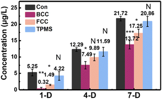
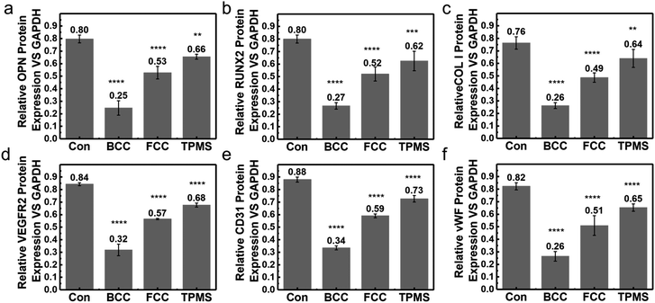
Differentiation of BMSCs to osteoblasts is a key step in the osteogenic phase. BMSC cell adhesion, proliferation, and osteoblast differentiation related to the expression of alkaline phosphatase (ALP), OPN, Runx2, Col-1, VEGFR2, vWF, and CD31. We measured the ALP activity by staining, an early indicator of osteoblast induction in BMSCs. Alkaline phosphatase is one of the markers of osteoblast maturation and plays a key role in the process of calcification in vitro. The main mechanism is the ability of alkaline phosphatase to initiate calcification by hydrolyzing the mailed phosphoric acids, increasing the local PO43− concentration, and destroying calcification inhibitors. The results can reveal that BMSCs can induce osteogenic differentiation on scaffolds at an early stage in an osteogenic differentiation medium. The ALP activity of BMSCs cells cultured in osteogenic induction media on the three different DLP 3D printed HA scaffolds on the 1st, 4th, and 7th day, as shown in Fig. 6, was the indication of osteoblastic differentiation. On the 7th day, there was a significant increase in ALP activity of the HA scaffolds compared to the 1st day, indicating increased osteoblast activity and bone formation. Overall, the ALP activities were expressed on all three HA structures, and the expression levels showed a trend of BCC < FCC < TPMS. After 7 days of incubation on the scaffolds, bone alkaline phosphatase (BALP) levels were 13.7 μg L−1 on the BCC scaffold (P < 0.01, statistically significant difference compared to blank group), 17.3 μg L−1 on the FCC scaffold (P < 0.01, statistically significant difference compared to blank group), and up to 20.9 μg L−1 on the TPMS scaffold (no statistically significant differences were seen compared to the blank group), respectively. TPMS structure exhibited the best ALP activity, which might be because TPMS structure had interconnected pore structures suitable for cell growth.27,41 The reported research showed that TPMS structure might be better for cell attachment by providing a larger area submitted to an adequate range of mechanical stimuli.45 Melchels et al.19 also demonstrated that 3D printed TPMS structure was more easily infiltrated and invaded by cell suspensions, resulting in a more uniform distribution of cells, and dense scaffolds with a relatively uniform distribution of cells were obtained after five days of sugar dispensing.The effect of scaffold liquid extract on the expression of six proteins related to osteogenic differentiation of BMSCs was investigated by western blot and immunofluorescence staining. Osteopontin (OPN) is a secreted, highly acidic phosphoprotein. It is necessary for the regulation of mineralized tissue formation and remodeling.51 Thus, increased expression of OPN is a marker for the cessation of osteoblast proliferation and the initiation of differentiation.52 Runx2 is thought to be a regulator of early osteoblast differentiation and plays a role in skeletal morphogenesis, chondrogenesis, and angiogenesis.53 VEGFR-2 induces migration and proliferation of endothelial cells in culture and has a strong angiogenic capacity in vivo. Neoangiogenesis in cartilage growth plates plays an important role in endochondral osteogenesis.54 It was demonstrated that VEGFR-2 stimulates the recruitment of blood vessels and osteoclasts and promotes cartilage resorption at the site of periosteal repair.55 Collagen-1 is a major component of natural bone and has an osteoconductive effect on bone regeneration.56,57 Osteogenic protein expression levels of rat bone marrow mesenchymal stem cells were observed after 21 days of osteogenic induction on scaffolds inoculated with three structures. Fig. 7 shows the expression of osteogenic proteins on DLP 3D printed HA scaffolds of BCC, FCC, and TPMS structures. Generally, from these testing, the expression levels of the six osteogenic proteins on the three structures showed a trend of BCC < FCC < TPMS, which was the same as that of ALP. These results further demonstrated the influence of structure on osteogenic differentiation.
As known, the osteogenic effect depends on a combination of many factors affecting the biomaterial.41 It has been demonstrated that porous attributes, mechanical properties, and biological behavior as well as bioactive components can effectively regulate cell attachment, proliferation, and differentiation. For porous scaffolds applied in bioengineering, in addition to the material itself must be biocompatible and degradable, the structure itself should also have bionic properties. The scaffold should have interconnected pores, uniform surface transition, high fine liquid mobility and diffusivity, and high specific strength. The point structure coming from simple Boolean operations is difficult to meet the needs of bioengineering, as verified by this experiment. This is because biological cell aggregates are easily separated by geometric features such as sharp turns and sharp corners formed. Therefore, such dot matrix structures including BCC and FCC cannot provide a suitable environment for cell attachment, migration, and proliferation. TPMS has been considered the ideal geometry to describe the morphology of the human skeletal structure. It has been shown that curved structures are more conducive to cell crawling and spreading and help to enhance plasma membrane extension. Truss-like lattice structures composed of straight rods do not have smooth and sufficiently large curved internal surfaces to ensure good cell flow and diffusion inside, and TPMS structures meet these requirements perfectly. At the same time, TPMS has high reproducibility and manufacturability, which will lead to a greater potential for scaffolds with TPMS structures in bone engineering. Similar results were first found by Zhang et al.,41 which gave a fundamental guide for this work.
4. Conclusions
In this paper, hydroxyapatite (HA) ceramic scaffolds with three different structural configurations, including the body-centered cubic (BCC), the face-centered cubic (FCC), and the triply periodic minimal surface (TPMS), were fabricated through digital light processing (DLP)-based 3D printing technologies. The effects of the structural configurations on the morphologies, and mechanical and in vitro behaviors of the DLP-based 3D printed HA scaffolds were characterized and discussed. The main conclusions are listed as follows,(1) All the DLP-based 3D-printed HA scaffolds had outstanding accuracy and surface quality.
(2) The compressive strengths of BCC, FCC, and TPMS under the porosity of 60 vol% were 0.42 ± 0.06 MPa, 1.46 ± 0.15 MPa, and 3.32 ± 0.32 MPa, respectively. As found, TPMS exhibited the highest compressive strength and the best mechanical behavior compared to BCC and FCC under the same porosity. The compressive strength of as-produced HA scaffolds barely met the strength requirements of the clinical application. Among these three HA scaffolds, TPMS seemed to have the most promising clinical application for bone regeneration.
(3) Cells exhibited no significant cell death on all three HA scaffolds, and large areas of cells survived well. This indicated that all the DLP 3D-printed HA scaffolds were biocompatible and that these HA scaffolds exhibited the potential to support cell growth.
(4) The ALP activities were expressed on all three HA structures, and the expression levels showed a trend of BCC < FCC < TPMS.
(5) The expression levels of the six osteogenic proteins on the three structures showed a trend of BCC < FCC < TPMS, which was the same as that of ALP.
Although TPMS scaffolds exhibit good mechanical properties, for example, the compressive strength of β-TCP material prepared by DLP by Xu et al.58 ranged from 0.8 to 4.1 MPa, and the compressive strength of BCP material prepared by Liu et al.59 was 1.06 MPa. However, compared with other inert ceramic materials made by additive manufacturing, for example, ZTA prepared by 3D printing by Yu et al.60 the material's bending strength can reach 422.5 MPa, and the scaffold has good cytocompatibility, which can promote cell adhesion and proliferation. Besides, it should be noted that the strength achieved in this work was still relatively low. Zhang et al.41 got gyroid TPMS structures with high strength ranging from about 3–15 MPa. How to enhance the strength of HA scaffolds with TPMS structures is still a big challenge in our future work.
It is indeed interesting to compare the compressive strength of a scaffold filled with osteoblasts with that of natural bone. However, since the scaffold is composed of HA, HA degrades when filled with osteoblasts. As the scaffold degrades, the number of osteoblasts will increase, and monitoring the compressive strength of the scaffold appears difficult, but this provides an interesting direction for our next experiments.
In sum, TPMS has high reproducibility and manufacturability, which will lead to a greater potential for scaffolds with TPMS structures in bone engineering. However, the mechanical properties and in vitro performance of the scaffolds of all three structures need to continue to be improved. The in vivo osteogenic effects of the three structures of the scaffolds still need to be explored.
Author contributions
Ke Liu, methodology, formal analysis, investigation, writing-original draft. Qing Zhou, formal analysis, investigation, writing-review & editing. Xueqin Zhang, formal analysis, investigation, writing-review & editing. Lili Ma, investigation, writing-review & editing. Baohua Xu, formal analysis, writing-review & editing, supervision, project administration, funding acquisition. All authors have read and agreed to the published version of the manuscript.Conflicts of interest
There are no conflicts to declare.Acknowledgements
This research was funded by the National Natural Science Foundation of China [52275310].References
- M. Bogala, Bioprinting, 2022, 28, e00244 CrossRef
.
- Y. y. Li, L. t. Li and B. Li, Mater. Des., 2015, 72, 16–20 CrossRef CAS
.
- Y. Zhu, K. Liu, J. Deng, J. Ye, F. Ai, H. Ouyang, T. Wu, J. Jia, X. Cheng and X. Wang, Int. J. Nanomed., 2019, 14, 5977–5987 CrossRef CAS PubMed
.
- F. Baino, E. Fiume, J. Barberi, S. Kargozar, J. Marchi, J. Massera and E. Verné, Int. J. Appl. Ceram. Technol., 2019, 16(5), 1762–1796 CrossRef CAS
.
- S.-J. Shih, D. R. M. Sari and Y.-C. Lin, Int. J. Appl. Ceram. Technol., 2016, 13(4), 787–794 CrossRef CAS
.
- F. Baino, E. Verné, E. Fiume, O. Peitl, E. D. Zanotto, S. M. Brandão and S. A. Schellini, Int. J. Appl. Ceram. Technol., 2019, 16(5), 1850–1863 CrossRef CAS
.
- R. Liu, L. Ma, H. Liu, B. Xu, C. Feng and R. He, Ceram. Int., 2021, 47(20), 28924–28931 CrossRef CAS
.
- H. Huang, A. Yang, J. Li, T. Sun, S. Yu, X. Lu, T. Guo, K. Duan, P. Zheng and J. Weng, Regener. Biomater., 2022, 9, rbac001 CrossRef CAS PubMed
.
- X. Li, Y. Yuan, L. Liu, Y.-S. Leung, Y. Chen, Y. Guo, Y. Chai and Y. Chen, Bio-Des. Manuf., 2019, 3(1), 15–29 CrossRef
.
- D. Zhao, F. Witte, F. Lu, J. Wang, J. Li and L. Qin, Biomaterials, 2017, 112, 287–302 CrossRef CAS PubMed
.
- I. Nemcakova, A. Litvinec, V. Mandys, S. Potocky, M. Plencner, M. Doubkova, O. Nanka, V. Olejnickova, B. Sankova, M. Bartos, E. Ukraintsev, O. Babcenko, L. Bacakova, A. Kromka, B. Rezek and D. Sedmera, Sci. Rep., 2022, 12(1), 5264 CrossRef CAS PubMed
.
- A. Kumar, S. Kargozar, F. Baino and S. S. Han, Front. Mater., 2019, 6, 313 CrossRef
.
- S. Bose, G. Fielding, S. Tarafder and A. Bandyopadhyay, Trends Biotechnol., 2013, 31(10), 594–605 CrossRef CAS PubMed
.
- S. Bose and S. Tarafder, Acta Biomater., 2012, 8(4), 1401–1421 CrossRef CAS PubMed
.
- M. Mohammadi Zerankeshi, S. Mofakhami and E. Salahinejad, Ceram. Int., 2022, 48(16), 22647–22663 CrossRef CAS
.
- S. Tarafder, N. M. Davies, A. Bandyopadhyay and S. Bose, Biomater. Sci., 2013, 1(12), 1250–1259 RSC
.
- C. Yan, L. Hao, A. Hussein and D. Raymont, Int. J. Mach. Tools Manuf., 2012, 62, 32–38 CrossRef
.
- S. Gomez, M. D. Vlad, J. Lopez and E. Fernandez, Acta Biomater., 2016, 42, 341–350 CrossRef CAS PubMed
.
- F. P. Melchels, A. M. Barradas, C. A. van Blitterswijk, J. de Boer, J. Feijen and D. W. Grijpma, Acta Biomater., 2010, 6(11), 4208–4217 CrossRef CAS PubMed
.
- Z. Cai, Z. Liu, X. Hu, H. Kuang and J. Zhai, Bio-Des. Manuf., 2019, 2(4), 242–255 CrossRef
.
- H. A. Zaharin, A. M. Abdul Rani, F. I. Azam, T. L. Ginta, N. Sallih, A. Ahmad, N. A. Yunus and T. Z. A. Zulkifli, Materials, 2018, 11(12), 2402 CrossRef CAS PubMed
.
- I. Zein, D. Hutmacher, K. Tan and S. Teoh, Biomaterials, 2002, 23(4), 1169–1185 CrossRef CAS PubMed
.
- S. Tarafder, V. K. Balla, N. M. Davies, A. Bandyopadhyay and S. Bose, J. Tissue Eng. Regener. Med., 2013, 7(8), 631–641 CrossRef CAS PubMed
.
- H. K. Lim, S. J. Hong, S. J. Byeon, S. M. Chung, S. W. On, B. E. Yang, J. H. Lee and S. H. Byun, Int. J. Mol. Sci., 2020, 21(18), 4837 Search PubMed
.
- M. Sari, P. Hening, Chotimah, I. D. Ana and Y. Yusuf, Mater. Today Commun., 2021, 26, 102135 CrossRef CAS
.
- W. Dietmar, J. Biomater. Sci., Polym. Ed., 2001, 12(1), 107–124 CrossRef PubMed
.
- B. Liao, R. F. Xia, W. Li, D. Lu and Z. M. Jin, J. Mater. Eng. Perform., 2021, 30(7), 4993–5004 CrossRef CAS
.
- X. Du, S. Fu and Y. Zhu, J. Mater. Chem. B., 2018, 6(27), 4397–4412 RSC
.
- L. Roseti, V. Parisi, M. Petretta, C. Cavallo, G. Desando, I. Bartolotti and B. Grigolo, Mater. Sci. Eng., C, 2017, 78, 1246–1262 CrossRef CAS PubMed
.
- Z. Chen, Z. Li, J. Li, C. Liu, C. Lao, Y. Fu, C. Liu, Y. Li, P. Wang and Y. He, J. Eur. Ceram. Soc., 2019, 39(4), 661–687 CrossRef CAS
.
- X. Zhang, K. Zhang, L. Zhang, W. Wang, Y. Li and R. He, Mater. Des., 2022, 215, 110470 CrossRef CAS
.
- C. J. Bae and J. W. Halloran, Int. J. Appl. Ceram. Technol., 2011, 8(6), 1255–1262 CrossRef CAS
.
- C. Feng, K. Zhang, R. He, G. Ding, M. Xia, X. Jin and C. Xie, J. Adv. Ceram., 2020, 9(3), 360–373 CrossRef CAS
.
- B. Zhang, X. Gui, P. Song, X. Xu, L. Guo, Y. Han, L. Wang, C. Zhou, Y. Fan and X. Zhang, ACS Appl. Mater. Interfaces, 2022, 14(7), 8804–8815 CrossRef CAS PubMed
.
- L. Zhang, B. Song, L. Yang and Y. Shi, Acta Biomater., 2020, 112, 298–315 CrossRef CAS PubMed
.
- D. Mahmoud and M. A. Elbestawi, Int. J. Adv. Manuf. Technol., 2018, 100(9–12), 2915–2927 Search PubMed
.
- A. Parisien, M. S. A. ElSayed and H. Frei, Today Commun., 2022, 33, 104315 CAS
.
- F. S. L. Bobbert, K. Lietaert, A. A. Eftekhari, B. Pouran, S. M. Ahmadi, H. Weinans and A. A. Zadpoor, Acta Biomater., 2017, 53, 572–584 CrossRef CAS PubMed
.
- R. Noroozi, M. A. Shamekhi, R. Mahmoudi, A. Zolfagharian, F. Asgari, A. Mousavizadeh, M. Bodaghi, A. Hadi and N. Haghighipour, Biomed. Mater., 2022, 17(4), 045024 CrossRef PubMed
.
- N. Wang, G. K. Meenashisundaram, S. Chang, J. Y. H. Fuh, S. T. Dheen and A. Senthil Kumar, J. Mech. Behav. Biomed. Mater., 2022, 129, 105151 CrossRef CAS PubMed
.
- Q. Zhang, L. Ma, X. Ji, Y. He, Y. Cui, X. Liu, C. Xuan, Z. Wang, W. Yang, M. Chai and X. Shi, Adv. Funct. Mater., 2022, 32, 2204182 CrossRef CAS
.
- X. Zhang, K. Zhang, B. Zhang, Y. Li and R. He, J. Eur. Ceram. Soc., 2022, 42(15), 7102–7112 CrossRef CAS
.
- X. Zhang, K. Zhang, B. Zhang, Y. Li and R. He, Virtual Phys. Prototyping, 2022, 17(3), 528–542 CrossRef
.
- C. Pitta Kruize, S. Panahkhahi and N. E. Putra, ACS Biomater. Sci. Eng., 2021 DOI:10.1021/acsbiomaterials.1c00620
.
- A. L. Olivares, E. Marsal, J. A. Planell and D. Lacroix, Biomaterials, 2009, 30(30), 6142–6149 CrossRef CAS PubMed
.
- J. Zhang, X. Chen, Y. Sun, J. Yang, R. Chen, Y. Xiong and W. Hou, Mater. Des., 2022, 218, 110665 CrossRef CAS
.
- S. Kanwar and S. Vijayavenkataraman, Mater. Des., 2022, 223, 111199 CrossRef
.
- M. E. Dokuz, M. Aydın and M. Uyaner, J. Mater. Eng. Perform., 2021, 30(9), 6938–6948 CrossRef CAS
.
- S. C. Cox, J. A. Thornby, G. J. Gibbons, M. A. Williams and K. K. Mallick, Mater. Sci. Eng., C, 2015, 47, 237–247 CrossRef CAS PubMed
.
- S. Chen, Y. Shi, X. Zhang and J. Ma, Ceram. Int., 2019, 45(8), 10991–10996 CrossRef CAS
.
- D. T. Denhardt and X. Guo, FASEB J., 1993, 7(15), 1475–1482 CrossRef CAS PubMed
.
- D. T. Denhardt, M. Noda, W. O. ’R. Anthony, D. Pavlin and J. S. Berman, J. Clin. Invest., 2001, 107(9), 1055–1061 CrossRef CAS PubMed
.
- M. Bruderer, R. G. Richards, M. Alini and M. J. Stoddart, Eur. Cells Mater., 2014, 28, 269–286 CrossRef CAS PubMed
.
- M. F. Carlevaro, S. Cermelli, R. Cancedda and F. Descalzi Cancedda, J. Cell Sci., 2000, 113, 59–69 CrossRef CAS PubMed
.
- K. Hu and B. R. Olsen, J. Clin. Invest., 2016, 126(2), 509–526 CrossRef PubMed
.
- R. Murugan and S. Ramakrishna, Compos. Sci. Technol., 2005, 65(15–16), 2385–2406 CrossRef CAS
.
- M. B. Alcantara, N. Nemazannikova, M. Elahy and C. R. Dass, J. Pharm. Pharmacol., 2014, 66(11), 1586–1592 CrossRef CAS PubMed
.
- S. Xu, H. Zhang, X. Li, X. Zhang, H. Liu, Y. Xiong, R. Gao and S. Yu, Proc. Inst. Mech. Eng., Part H, 2022, 236, 286–294 CrossRef PubMed
.
- G. Liu, B. Zhang, T. Wan, C. Zhou, Y. Fan, W. Tian and W. Jing, J. Mater. Chem. B, 2022, 10, 3138–3151 RSC
.
- T. Yu, X. Zhu, H. Yu, P. Wu, C. Li, X. Han and M. Chen, J. Manuf. Process., 2023, 94, 120–132 CrossRef
.
| This journal is © The Royal Society of Chemistry 2023 |

