
 Open Access Article
 This Open Access Article is licensed under a Creative Commons Attribution-Non Commercial 3.0 Unported Licence
Fabrication of novel strain sensors from green TPV nanocomposites based on poly(3-hydroxybutyrate-co-3-hydroxyvalerate) (PHBV)/silicone rubber/silicon-modified graphene oxide†
Ali Moshkriza,
Zahra Shahroodi b and
Reza Darvishi*c
b and
Reza Darvishi*c
aDepartment of Chemical Engineering, Faculty of Engineering, Arak University, Arak, 38156-8-8349, Iran
bInstitue of Polymer Processing, Montanuniversitaet Leoben, 8700 Leoben, Austria
cDepartment of Gas and Petroleum, Yasouj University, Gachsaran, 75918-74831, Iran. E-mail: r.darvishi@yu.ac.ir
First published on 13th June 2023
Abstract
In this study, a new thermoplastic vulcanizate (TPV) blend of silicone rubber (SR) and poly (3-hydroxybutyrate-co-3-hydroxy valerate) (PHBV) including silicon-modified graphene oxide (SMGO), is used to fabricate highly flexible and sensitive strain sensors. The sensors are built with an extremely low percolation threshold of 1.3 vol%. We investigated the effect of adding SMGO nanoparticles to strain-sensing applications. The findings demonstrated that increasing the SMGO concentration enhanced the composite's mechanical, rheological, morphological, dynamic mechanical, electrical, and strain-sensing capabilities. But too many SMGO particles can reduce elasticity and cause nanoparticle aggregation. The nanocomposite's gauge factor (GF) values were discovered to be 375, 163, and 38, with nanofiller contents of 5.0 wt%, 3.0 wt%, and 1.0 wt% respectively. Cyclic strain-sensing behavior showed their ability to recognize and classify various motions. Due to its superior strain-sensing capabilities, TPV5 was chosen to assess the repeatability and stability of this material when utilized as a strain sensor. The sensor's excellent stretchability, sensitivity (GF = 375), and remarkable repeatability during cyclic tensile testing allowed them to be stretched beyond 100% of the applied strain. This study offers a new and valuable method for building conductive networks in polymer composites, with potential uses in strain sensing, especially in biomedical applications. The study also emphasizes the potential of SMGO as a conductive filler for developing extremely sensitive and flexible TPEs with enhanced, environmentally friendly features.
Introduction
Thermoplastic vulcanizates (TPVs) are a type of high-performance thermoplastic elastomer created through dynamic vulcanization (DV), characterized by a significant proportion of crosslinked rubber as the dispersed phase and a lower amount of thermoplastics as the continuous phase.1 This unique composition imparts TPVs with a combination of mechanical properties, such as excellent resilience, tensile strength, and elongation at break, comparable to traditional vulcanized elastomers. Additionally, TPVs exhibit the processability and recyclability of thermoplastics, allowing for efficient manufacturing and reduced environmental impact. The microstructure of TPVs plays a crucial role in determining their properties. Factors such as the content and degree of crosslinking of the rubber phase, size and size distribution of the rubber particles, rubber network structure, thickness of plastic ligaments, and compatibility between rubber and plastic all contribute to the overall performance of TPVs. Researchers have extensively studied the influence of these factors on the mechanical, elastic, and rheological attributes of TPVs, aiming to optimize their performance for specific applications.2–4TPVs have gained significant popularity as the fastest-growing elastomers in recent years due to their ability to replace unrecyclable thermoset rubbers. This characteristic aligns with the increasing emphasis on environmental protection and resource conservation. The automotive, construction, and electronic cable production industries have widely adopted TPVs as “green” elastomers, benefiting from their superior properties and sustainability advantages.5 Moreover, TPVs hold great potential in biomedical applications, particularly in the development of medical implants. Their unique combination of flexibility, durability, and biocompatibility allows for the creation of implants that conform to the body's shape, enabling natural motion.6,7 For instance, TPVs can be used to fabricate heart valve implants that mimic the heart's movement.8 Additionally, TPVs are suitable for medical devices like catheters, tubing, and syringes, which require both flexibility and durability.9 This study developed a novel non-petroleum-based options to address the need for sustainable alternatives to petroleum-based TPVs. For example, the use of renewable polymers such as polylactic acid (PLA) and polyhydroxyalkanoates (PHA) has been investigated in combination with natural rubber (NR) or epoxidized natural rubber (ENR) to improve the toughness and shape memory behaviors of TPVs. These bio-based TPVs offer comparable performance to their petroleum-based counterparts while reducing reliance on fossil fuels and minimizing environmental impact.10
In the pursuit of sustainable TPVs, the current study focuses on the development of a non-petroleum-based TPV using a silicon rubber (SR) blend with poly(3-hydroxybutyrate-co-3-hydroxyvalerate) (PHBV). SR, composed of a Si–O–Si main chain, exhibits excellent low-temperature flexibility, high-temperature stability, and biocompatibility, making it an ideal choice for TPV formulations.11 On the other hand, PHBV is an eco-friendly and renewable polymer known for its thermal and chemical resistance, biodegradability, processability, and biocompatibility.12 By combining these two materials, we aim to create a sustainable TPV with enhanced properties. However, the SR/PHBV blend faces challenges related to poor compatibility and phase inversion during dynamic vulcanization. The differing solubility parameters and polarities between SR and PHBV result in mutual immiscibility, leading to coarse morphologies and inferior mechanical properties in TPVs. Additionally, the low viscosity of SR prevents the effective breaking of the PHBV phase, resulting in distinct phase separation and further difficulties in phase inversion. The study aims to address these issues by improving compatibility and matching the viscosities of the two phases, thereby optimizing the properties of the TPVs.
Furthermore, to enhance the properties of TPVs, various nanoparticles have been explored as fillers. In previous studies, carbon black and nanocaly have been utilized, while graphene oxide (GO) stands out as a critical filler due to its exceptional properties, including high thermal stability, excellent processability, good electrical conductivity, and high mechanical strength.13 GO's two-dimensional structure, coupled with its surface's oxygen-containing functional groups, makes it an ideal candidate for nanocomposites. Additionally, the high surface area and functional groups of GO contribute to improved dispersion and reinforcement within polymer matrices.14 In this study, the researchers incorporate silicone-modified graphene oxide (SMGO) as a filler to enhance the dispersion of the SR phase in the PHBV matrix, resulting in a finer morphology and a more uniform distribution of the crosslinked rubber phase. SMGO, a graphene-based filler functionalized with silicone groups, offers improved dispersibility in polymer matrices, reduced aggregation tendency, and enhanced mechanical and electrical properties of the TPVs.
Moreover, the developed TPVs have potential applications in the field of flexible piezoresistive strain sensors (FPSS). These sensors, used in human motion detection, health monitoring, biomedical detectors, and smart robotics, rely on the piezoresistivity of materials to detect mechanical deformations and pressure changes.15 Conductive TPVs, characterized by their stretchability, high conductivity, and superior mechanical properties, have emerged as promising materials for high-performance strain sensors.16 By applying external strain, conductive fillers within the TPV matrix undergo rearrangement, leading to changes in electrical resistance. The study aims to optimize the TPV formulation and investigate the composites' blend morphology, mechanical, rheological, dynamic mechanical, and electrical properties to develop a highly sensitive and stretchable TPV for strain-sensing applications.17
In summary, this research paper presents a comprehensive investigation on the development of conductive and piezoresistive sensing TPVs using an SR/PHBV blend and SMGO as a conductive filler for the first time. The study explores the effects of blend morphology and SMGO content on the mechanical, rheological, dynamic mechanical, and electrical properties of the TPVs. Furthermore, the strain-sensing performance of the optimized TPVs is evaluated through static and dynamic analyses. The findings contribute to the advancement of sustainable TPVs and their potential applications in various fields, particularly in developing of flexible strain sensors for detecting human body motion.
Experimental
Materials
Poly(3-hydroxybutyrate-co-3-valerate), PHBV, as a bacterial thermoplastic bio-polyester, ENMAT PHBV resin, Y1000P, obtained from TianAn Biopolymer, China. Melting temperature (Tm) and melt flow rate (MFR) of PHBV, as noted from the TDS, are 174 °C and 12.4 g 10 min−1 (180 °C, 2.16 kg), vinyl-terminated polydimethylsiloxane polymer (SiSiB® VF6030-200, vinyl content 0.4–0.6, viscosity at 25 °C 180–220 cS) was purchased from SINOPCC Group. Ltd, China, platinum(0)-1,3-divinyl-1,1,3,3-tetramethyl disiloxane complex (Kastedt's catalyst, as a curing agent with platinum content of 2000 ppm), and Guangzhou Xiyou New Material Technology Co., Ltd China supplied 1-ethynyl cyclohexanol, ECX (as an inhibitor). Graphite flakes (Sigma-Aldrich, with a mesh size of 150 μm), tris (pentafluorophenyl) borane ((C6F5)3B) Greener, hydride-functional silicones: poly(dimethylsiloxane) hydroxy-terminated (PDHT), liquid form, number average molecular weight ∼550 kg mol−1, and viscosity ∼25 cSt was purchased from Biosynth. Sulfuric acid (analytical purity, 98%) was provided by Tianjin Third Chemical Factory (Tianjin, China). In addition, Toluene (AR), sodium nitrate (NaNO3, AR), potassium permanganate (KMnO4, AR), and hydrogen peroxide (H2O2,30% AR) were purchased from Damao Chemical Reagent Factory (Tianjin, China).Preparation of graphene oxide (GO)
GO was synthesized according to the modified Hummers' method.18 In brief, graphite powder (3 g) was mixed with sodium nitrate (NaNO3) (1 g) and sulfuric acid (H2SO4) (46 mL) in an ice bath. Potassium manganese oxide (KMnO4) (18 g) was slowly added to the mixture with constant stirring, and the temperature was raised to 35 °C for 2 hours. The reaction was terminated by adding deionized water (230 mL) and H2O2 (5 mL, 30% w/v). The resulting mixture was centrifuged at 5000 rpm for 10 min, and the supernatant was discarded. The obtained GO powder was washed several times with deionized water until the pH of the filtrate reached 7. The GO powder was then dried under a vacuum at 60 °C for 12 hours.Preparation of silicone-modified graphene oxide (SMGO)
GO flakes (300 mg) were dispersed in poly(dimethyl hydrogen siloxane-co-methyl vinyl siloxane) (PDHT) (150 mL) in a 500 mL round-bottom flask. Tris(pentafluorophenyl)borane (C6F5)3B (60 mg, 0.12 mmol) was added as a catalyst for the crosslinking step, and glass beads (number 30, diameter 8 mm) were added to facilitate the reaction at the interface and disrupt the graphene oxide stacks. The reaction mixture was stirred at 40 °C for 24 hours under a dry nitrogen atmosphere. After the reaction, toluene was substituted for the PDHT to achieve the desired results. The modified graphene oxide was washed with dry toluene to remove ungrafted silicones. The SMGO was dried at 50 °C under a vacuum of 6.165 kPa for 24 hours in a microwave oven.19 Fig. 1 shows the scheme for GO synthesis using Hummers' method and preparation of organosilanes/siloxane-modified GO (SMGO).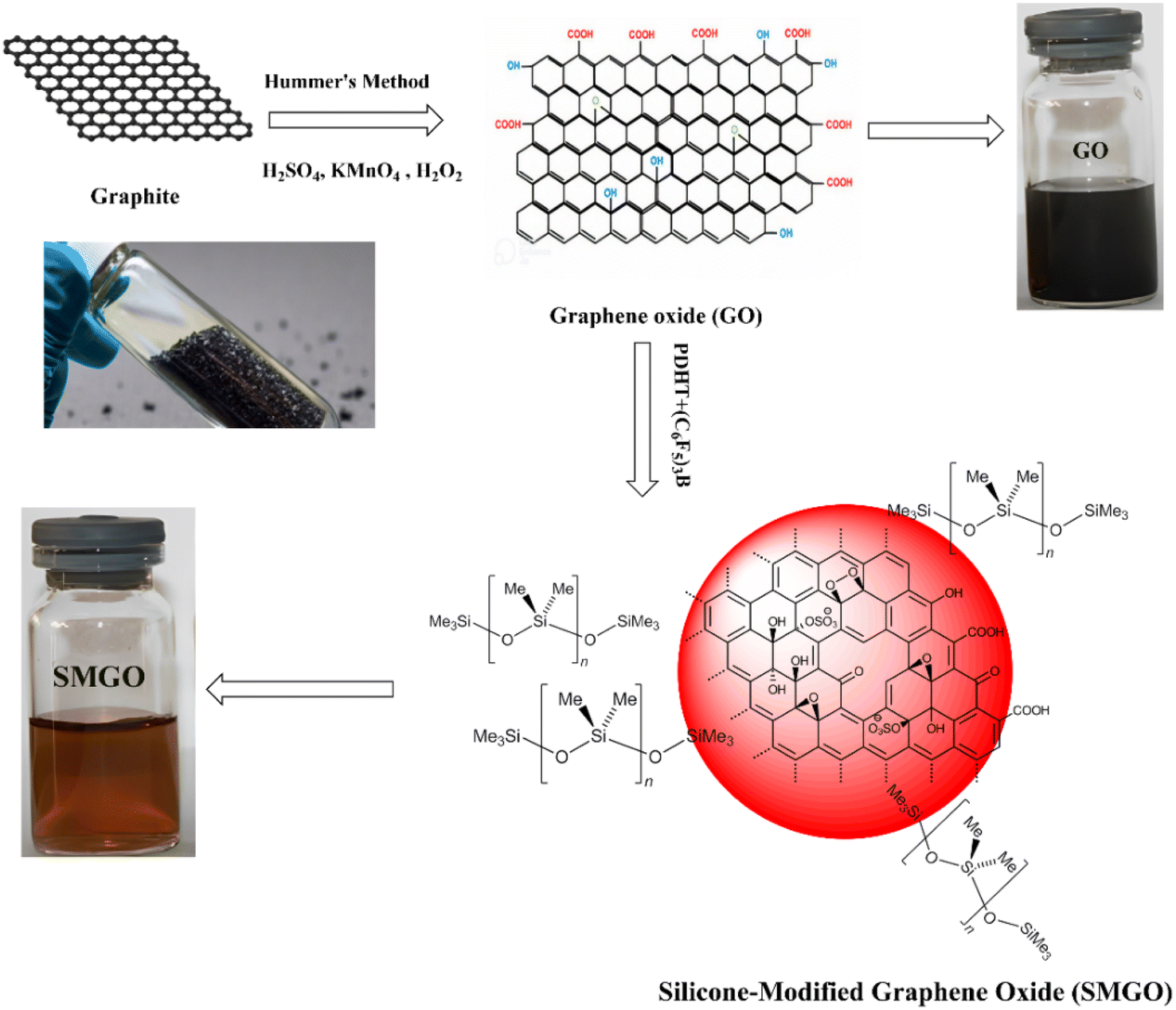 | ||
| Fig. 1 Scheme for preparation of organosilanes/siloxane-modified GO (SMGO). | ||
SMGO/PHBV/SR masterbatch preparation (SMGO MB)
A two-step process was used to prepare a masterbatch containing SMGO, PHBV, and SR. Initially, SMGO nanoparticles were blended with SR using a two-roller mill at a temperature of 55–60 °C for approximately 7 minutes, ensuring adequate mixing of the particles. This step was intended to improve SMGO particles' adhesion to the SR polymer chains. The mixture was transferred to a plastic bag and thoroughly mixed in the second step. The masterbatch was created to ensure the complete dispersion of SMGO within the base polymer resin; for further information regarding the compositions, see Table 1.| Component | TPV0 | TPV1 | TPV3 | TPV5 | TPV7 | Pt catalyst | ECX inhibitor | AO 1010 |
|---|---|---|---|---|---|---|---|---|
| SR [wt%] | 60 (0.6) | 55 | 45 | 35 | 25 | 0.5 | 0.02 | 0.001 |
| PHBV [wt%] | 40 (0.4) | 35 | 25 | 15 | 5 | 0.5 | 0.02 | 0.001 |
| MB [wt%] | 0 | 10 | 30 | 50 | 70 | 0.5 | 0.02 | 0.001 |
| Total | 100 | 100 | 100 | 100 | 100 | 0.5 | 0.02 | 0.001 |
| Nano [wt%] | 0 | 1 | 3 | 5 | 7 | 0.5 | 0.02 | 0.001 |
In-suite dynamic vulcanization of PP/SR/SMGO blends
For this research, all TPV samples utilized had a constant PHBV/SR weight ratio of 40/60 (w/w). Dynamic vulcanization was performed on the PHBV, SR, and SMGO blends in a Brabender at a temperature of 165 °C. The SMGO/PHBV/SR masterbatch was mixed with PHBV and SR, and the resulting mixture was added to the chamber. After approximately 3 minutes, a pre-mixture powder of Pt catalyst/ECX/AO.1010 was added as a curing system (0.5/0.02/0.001 wt% based on the total weight of the resins in the batch) to initiate dynamic vulcanization. The dynamically vulcanized blends were removed from the chamber once the final stable torque was reached and allowed to cool to room temperature. The entire process was completed in 10 minutes. Once crosslinked samples were obtained, each 1 mm thick sheet was hot-pressed at 180 °C to ensure uniform thickness (Table 1). Fig. 2 also shows a mechanism of TPV sample preparation.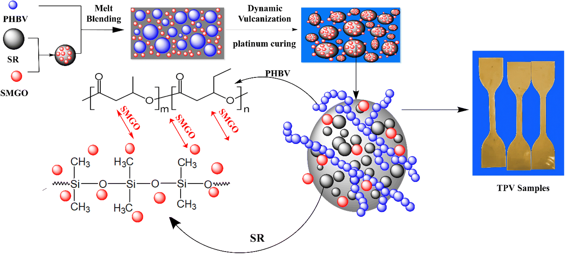 | ||
| Fig. 2 Scheme for preparation of SR/PHBV/SMGO TPV samples. | ||
Characterization
Mechanical properties
The mechanical properties of the samples were evaluated using dumbbell-shaped bars based on ASTM D412 (standard test methods for vulcanized rubber and thermoplastic elastomers—tension), which were tested using a universal tester (ZwickRoell, Germany) at a cross-head speed of 500.0 mm min−1 at room temperature. For the monotonic tensile test, at least five specimens with dimensions of 25 × 4 × 1 mm3 were tested for each group of samples. For the cyclic tensile test, the specimens were stretched to a strain of 50% in each cycle. The hardness of the samples was measured using a Durometer (Rex Gauge, USA) (Shore A type) in accordance with ASTMD 2240 (the mechanical test was carried out five times, and the average of the results was reported).Rheological measurements
The study employed a rotational rheometer (MCR-501 rheometer, Anton Paar, Austria) with a parallel-plate geometry and a diameter of 20 mm to measure rheological properties. The amplitude sweep test was done beforehand, and the strain was set at 1% to measure the linear viscoelastic region. A frequency sweep was conducted within the frequency range of 0.01 to 100 Hz at a constant temperature of 180 °C.Dynamic mechanical property
DMA tests of the blend were carried out on a TRITEC 2000 DMTA (Triton Technology Ltd, UK) in tension mode using rectangular samples with 10 × 30 × 1.5 mm dimensions. Loss factor (tan![[thin space (1/6-em)]](https://www.rsc.org/images/entities/char_2009.gif) δ) was recorded as a function of temperature from −120 to 70 °C at a heating rate of 2 °C min−1 and a frequency of 10 Hz.
δ) was recorded as a function of temperature from −120 to 70 °C at a heating rate of 2 °C min−1 and a frequency of 10 Hz.
Morphology characterization
To examine the morphology of the created TPVs, a field-emission scanning electron microscope (FE-SEM TESCAN, Czech Republic) was utilized, operating at 15 kV. The samples were fractured in liquid nitrogen to avoid phase deformation during breaking. After fracturing, the PHBV matrix was separated by exposing the fractured surface to dichloromethane (DCM) for an hour. To eliminate any solvent contamination, the samples were dried at 50 °C for six hours in a vacuum oven. The dried TPV surfaces were then coated with gold and visualized using the FE-SEM apparatus to prepare the graphs. Also, the morphology of the selected samples was examined using a Atomic Force Microscopy (AFM DME, E 95-200, Denmark) was employed to obtain high-resolution information about the surface morphology of the prepared TPVs. Prior to observation, the samples were polished at −130 °C using a cryo-ultramicrotome (Leica EM UC7, Germany).X-ray diffraction (XRD)
XRD analysis was conducted using a Philips X-pert X-ray diffractometer operating at 40 kV, with Cu as the radiation source (λ = 0.1540 nm). For the testing of GO and SMGO, scans were obtained with a scan step size of 0.03 and a scan step time of 0.25 seconds.Electrical property
The specimens' electrical conductivity was assessed using a Keithley 6487 picoammeter (Keithley Instruments, USA), and a constant voltage of 1 V was maintained to avoid high electric current through the samples. The specimens were rectangular cross-sectional bars cut out from compression-molded plates with dimensions of 25 mm in length, 4 mm in width, and 1 mm in thickness. To minimize contact resistance, silver paint was applied to the edges of the samples.Resistance response and strain-sensing behaviors
The real-time resistance response of the SMGO TPV composite under monotone and cyclic loading was monitored and recorded using a strain-sensing instrument developed at home.20 Each experiment was carried out at room temperature via a cross-head speed of 5 mm per minute. For testing, dumbbell-like DIN S2 samples were attached to two brass electrode plates with a gauge length of 35 mm. The relative resistance change R/R0 was calculated through the initial resistance R0 and the resistance change R = RaR0, in which Ra is the actual resistance at a given strain value. In addition, the dynamic strain-sensing behaviors of conductive composites have been examined using an electromechanical coupling test apparatus composed of a universal testing machine and a digital multimeter (S1). The universal tensile tester gets cyclic loading at a predetermined strain rate, and the Keithley DMM 7510 was utilized to measure the sample's resistance signal during cyclic loading. In the electromechanical test, samples measuring 60 mm by 6 mm by 2 mm were used. With a 10 mm min−1 loading pace, the gauge length, or the distance between the resistance measurement points, was 20 mm. A large deformation extensometer was used to measure strain in the examinations accurately. Each experiment was repeated five times to assess the repeatability of the test results.Thermogravimetric analysis
Thermogravimetric analysis (TGA) was performed to assess the thermal stability of the nanocomposites using a Mettler-Toledo AG, Switzerland. The samples were heated from 100 to 600 °C at a constant rate of 10 °C min−1 under a nitrogen atmosphere.Results and discussion
Dynamic vulcanization (DV)
![[double bond, length as m-dash]](https://www.rsc.org/images/entities/char_e001.gif) C), resulting in a crosslinked network structure. The curing system also includes ECX as an inhibitor to prevent over-curing. ECX reacts with residual platinum catalysts to form an inactive complex, which ensures that the cured material maintains its physical properties.
C), resulting in a crosslinked network structure. The curing system also includes ECX as an inhibitor to prevent over-curing. ECX reacts with residual platinum catalysts to form an inactive complex, which ensures that the cured material maintains its physical properties.Hydrosilation reaction:
| SiH + RCHCH2 → RCH2–Si–CH2–CH2–Si–CH2–R |
Inhibition of residual platinum catalyst:
| Pt catalyst + ECX → inactive complex |
The synthetic reaction of silicone rubber with platinum (Pt):
| R1–SiH + R2–CHCH2 + Pt catalyst → R1–Si–R2–CH2–CH2–Si–R1 + Pt |
In the hydrosilation reaction between a silicon–hydrogen bond and a carbon–carbon double bond in the presence of a platinum catalyst, R1 and R2 are organic groups that can be attached to the silicon and carbon atoms, respectively. They are typically methyl or vinyl groups in silicone rubber chemistry. The specific nature of the R1 and R2 groups can affect the properties of the resulting crosslinked network structure, including its mechanical properties, thermal stability, and chemical resistance.21
For studying the vulcanization process, TPV samples were chosen based on the torque-time and temperature–time (T) curves, which indicate the crosslinking of the rubber phase of the TPV0 sample. The rubber phase's crosslinking ratio was determined by the swelling ratio (Q) and the gel content (% gel), and the results are presented in (Fig. 3). Q exhibited a sharp decrease followed by a plateau with increasing the mixing time, while gel content initially increased, peaked at 6 min, and then plateaued.
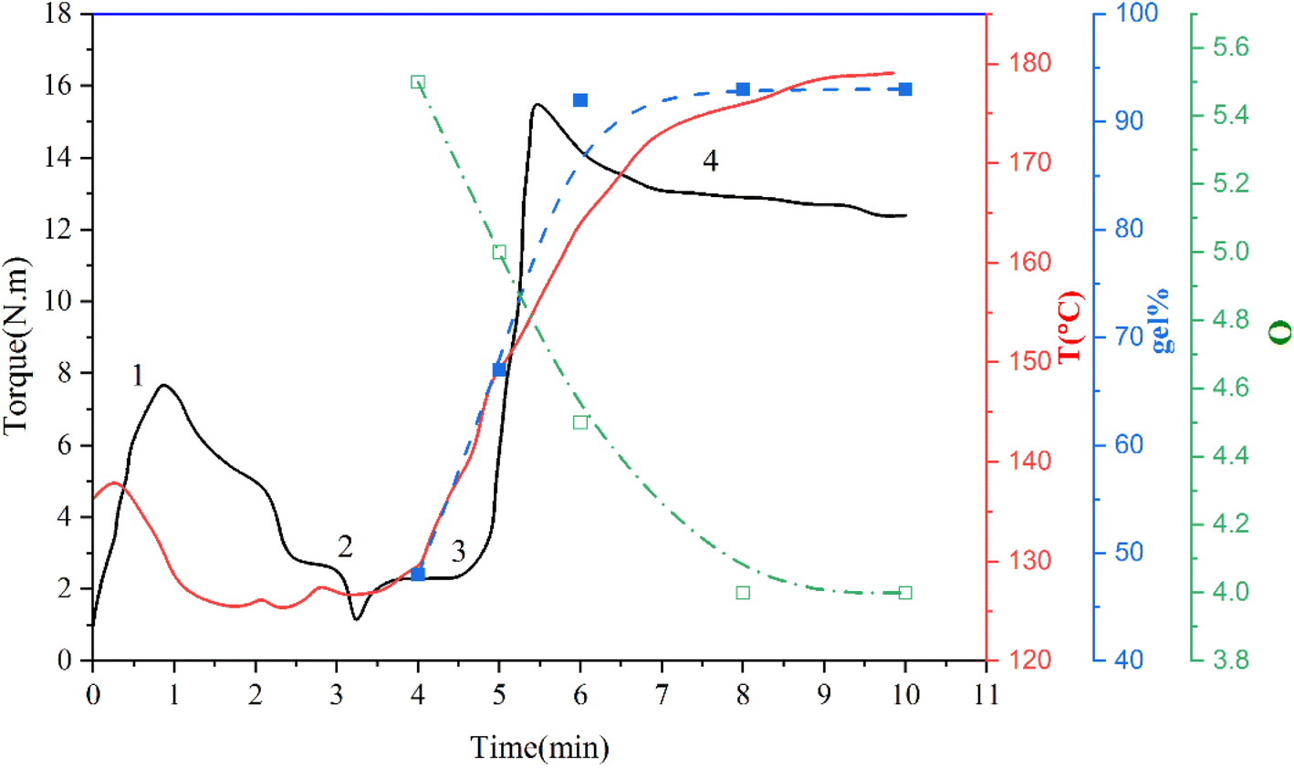 | ||
| Fig. 3 The chart displays the evolution of torque (M), temperature (T), swell ratio (Q), and rubber gel content (% gel) of a blend consisting of SR and PHBV in a 60/40 ratio throughout the process of DV at different times. | ||
(1) Melting zone (0–2 min), which is related to the melting of the blend (SR/PHBV/SMGO MB).
(2) Curing system introduction zone starting from around 3 min (Pt + ECX).
(3) Vulcanization zone.
(4) Equilibrium region where the torque has reached a plateau. This zone serves as an indicator of the degree of vulcanization.
In this case, neat TPV was examined five times to investigate its properties. The gel content and swelling ratio of gel were calculated using the following equations:
 | (1) |
 | (2) |
 | ||
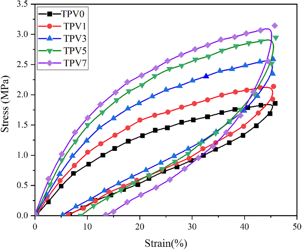
| Fig. 4 Stress–strain curves of various TPVs. | ||
The preferential nanofiller localization occurs when nanofillers are dispersed in polymer blends or thermoplastic elastomers.22 The SMGO as a nanofiller tends to locate in one phase or at the interface between the phases depending on the system's interfacial energy and wetting coefficient. The preferential localization of SMGO can affect the morphology and mechanical properties of the TPV nanocomposites. Selective localization of carbon nanotubes at the interface of other polymeric composites can improve the tensile strength and elongation at break by enhancing the interfacial adhesion and load transfer.23 The excellent compatibility between SMGO and SR and the interfacial interaction between the dispersed phase of SR droplets and the PHBV phase contributed to the improvements in mechanical properties. In conclusion, incorporating SMGO into TPV can significantly enhance various physical properties of TPV, but attention must be given to the SMGO content to avoid negative effects on the composite.
 | ||
| Fig. 5 Stretching–recovery curves of TPV composites with different contents of SMGO: TPV0 to TPV7. | ||
Moreover, incorporating SMGO into the system increases the permanent strain and the hysteresis loss. This demonstrates that the SMGO filler, dispersed among the SR polymer chains, reduces the movability of molecules. This results in stress concentration at the polymer/fillers interface and irreversible slip between the polymer matrix and the nanofillers, leading to more considerable permanent strain. At the same time, the tensile strength shows a notable enhancement. Nonetheless, the hysteresis loss of TPV0 to TPV7 is 55.18%, 51.75%, 44.89%, 32.52%, and 58.46%, respectively, and the permanent set for TPV0 to TPV7 is 6.34, 5.58%, 5.28%, 8.77%, 13.52%. According to the standard of ASTM D1566-07a, all these composites are elastomers with high elasticity.
Rheological properties
It is well-known that the rheological assessment can give a deep understanding of structure formation, morphology development, nanostructure formation, and interaction between phases. To investigate melt flow behavior, rotational rheological measurements of the vulcanized samples were conducted on the nanocomposites. The dependency of storage modulus (G′) on frequency is depicted in Fig. 6A. G′ represents the energy stored in samples. TPV0 shows a liquid-like behavior, where G′ increases with frequency. However, the nanocomposite TPVs show semi-solid-like and ideal elastic behavior, where G′ becomes independent of the frequency and mean the sample achieved rheological percolation. Increasing nanoparticle loading at a constant blend ratio (SR60/PHBV40) increased G, and more considerable differences are observable at lower frequencies (longer times).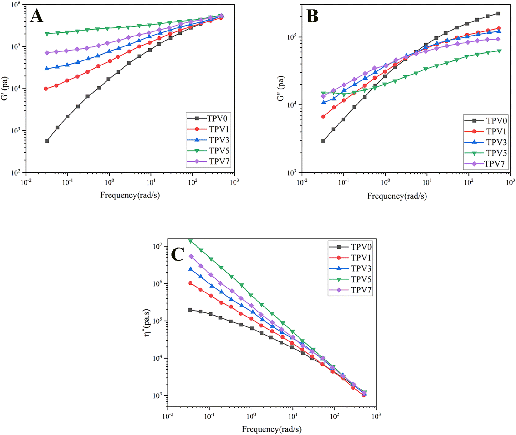 | ||
| Fig. 6 The graphs showing the (A) G′, (B) G′′, and (C) complex viscosity (η*) plotted against frequency at 180 °C were generated for TPVs consisting of PHBV and SR at varying SMGO content levels. | ||
TPV5 has the highest G′, which may be attributed to the uniform network formation. It is known that the elasticity of the melt increases while a solid network is present in a sample. Furthermore, a noticeable plateau in TPV5 and TPV7 shows that G′ is entirely independent of the frequency of the nanoparticle networks' presence. It is clear that by increasing the SMGO content and approaching the percolation threshold, G′ shifted to higher amounts, and a non-terminal behavior is observed. However, TPV5 has higher melt elasticity than TPV7, which can be related to more regular networks connecting throughout the sample and the presence of probable agglomerates in TPV7. Also, TPV5 shows almost a plateau in the whole frequency range, confirming the strong network where polymer chains and nanoparticles have strong interactions. The presence of networks is also investigated via SEM.
Furthermore, the liquid-to-solid transition frequency increases with increasing the amount of nanofiller, showing more networking than aggregation. Therefore, it can be concluded that 5 wt% SMGO is the percolation threshold in SR/PHBV TPVs.
Fig. 6B represents the dependency of G′′ to frequency for all samples. All the samples showed an increase in G′′ with frequency. But the slope of G′′ against frequency decreases with increasing SMGO content, and an obvious plateau is observable in TPV5. The plateau region at low frequencies in TPV5 is another indicator of the network present in the system even at longer times. Although we believe there should be SMGO networks in TPV7 nanocomposite, the networks break down longer in a constant strain amplitude, showing viscous dissipation at lower frequencies. Furthermore, TPV5 offers the lowest energy dissipation at high frequencies, which is another indicator of semi-solid-like behavior due to the perfect SMGO network present in this sample; by reducing the amount of SMGO particles, energy dissipation increases. This vicious behavior will further investigate the dependency of complex viscosity on frequency. The dependence of complex viscosity on frequency further explains nanocomposites' processability and structure formation.
Another important rheological parameter directly influenced by morphological characteristics and shows the processability of the nanocomposite is complex viscosity (Fig. 6C). All samples show sheathing behavior where the viscosity decreases with increasing frequency, and the difference in the complex viscosity of samples becomes significant at lower frequencies. By increasing the nanofiller content, complex viscosity increases. Like other rheological properties, TPV5 shows the highest viscosity mainly due to the solid-like behavior and perfect SMGO networks in this nanocomposite. In general, the increase in the complex viscosity can result from either polymer–polymer, nano–nano, or nano–polymer interactions, where nano–nano interactions significantly affect the rheological properties.24,25 The state of dispersion and distribution of nanoparticles resulted in more polymer–nano interactions. Furthermore, forming perfect networks tremendously enhance complex viscosity in the molten state and mechanical properties in the solid state.
In conclusion, by adding nanoparticles to TPV0, the viscous behavior of samples changes to the solid-like behavior, and good dispersion of SMGO is achieved in all TPV nanocomposites, especially TPV5. Furthermore, GO's high aspect ratio and high surface area can act as lubricants, reducing the friction between polymer chains and improving the flow properties of the composite. This can enhance the processability of the polymer composite. Additionally, GO can act as a nucleating agent, promoting the formation of smaller and more uniform crystallites during cooling, resulting in better processing properties of the composite. Furthermore, it can improve the composite's thermal stability, increasing the processing window and reducing the risk of degradation during processing.
Strain sweep of TPV samples
The analysis shows that the Payne effect was observed in all the TPV samples, and the result was more pronounced in samples with higher SMGO content. The Payne effect was due to the deformation of physical bonds connecting adjacent nanoparticle clusters, which required energy increasing the dynamic loss modulus (G′′).26 The G′ values remained relatively constant at small-strain amplitudes for all samples, indicating that the samples exhibited linear viscoelastic behavior. As the strain amplitude increased, the G′ values decreased rapidly due to the deformation of physical bonds between the nanoparticles (Fig. 7A). The decrease in G′ was more significant in samples with higher SMGO content, indicating that the SMGO particles had a more significant effect on the mechanical properties of the TPV samples.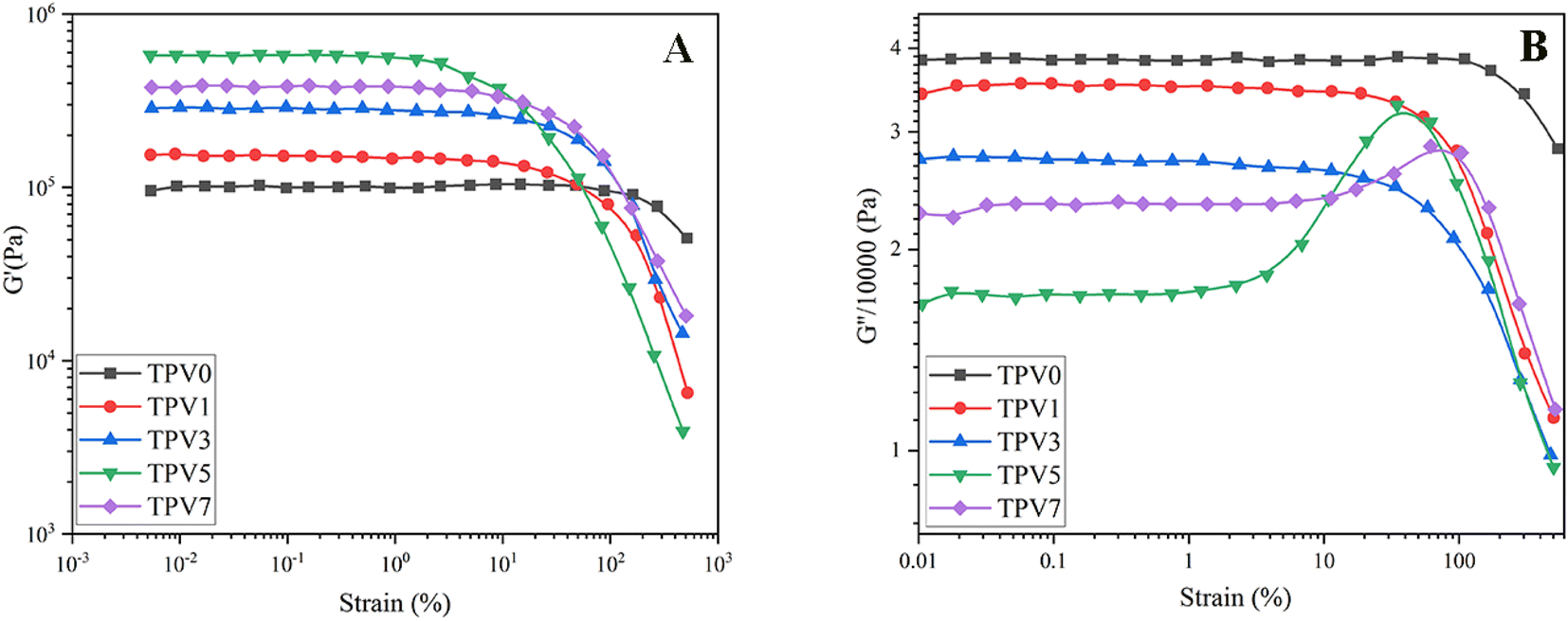 | ||
| Fig. 7 (A) The dynamic storage modulus (G′) and (B) loss modulus (G′′) of various thermoplastic vulcanizates (TPVs) consisting of PHBV and SR was measured at 200 °C and 10 rad s−1. The measurements were taken to determine the dependence of G′ and G′′ on strain amplitude. | ||
Furthermore, the G′′ values decreased with increasing SMGO content, indicating that the TPV samples exhibited a more elastic behavior with increasing SMGO content. However, a peak in G′′ was observed for samples with 5 and 7 wt% SMGO, corresponding to the destruction and reconstruction of the physical network formed by the SR phase in the PHBV matrix (Fig. 7B). At high SMGO content, the SR network was more susceptible to break into smaller SR aggregates but also easier to rebuild due to a higher SR ratio and more significant contact. The breaking and rebuilding of the SR network required energy, resulting in an increase in G′′ under suitable strains. As strain continued to rise, the reconstruction of the SR network became increasingly difficult, resulting in a decrease in energy loss and G′′. Therefore, the peak in G′′ corresponded to the balance between the destruction and reconstruction of the SR networks, which was affected by the SMGO content in the TPV samples.
The analysis provides insights into the mechanism of the Payne effect in filled TPV materials and its influence on the mechanical properties of TPV samples. The study also highlights the importance of controlling the particle size, distribution, and interparticle interactions to minimize the Payne effect and improve the mechanical properties of filled TPV nanocomposites. The findings of this study may have significant implications for developing high-performance TPV materials for various industrial applications.
Dynamic mechanical property
Dynamic mechanical analysis (DMS) was used at the constant frequency of 10 Hz to investigate further the viscoelastic behavior of TPV nanocomposites in the solid state. The results are presented in Fig. 8. The presence of two peaks in the loss factor (tanδ) is due to the presence of two phases in the sample. The peak around −120 to −97 °C is related to the glass transition (Tg) of the SR phase in the sample, and the one around 10–30 °C is Tg of the PHBV phase. By increasing the SMGO content, the Tg of the rubber phase increases. The increase in Tg values with increasing SMGO content in the PHBV/silicon rubber/SMGO nanocomposite can be attributed to the reinforcing effect of SMGO on the matrix. As the SMGO content rises, it can interact with the polymer chains and improve the interfacial interactions between the components, leading to a more rigid and stable matrix. This increase in values can also be attributed to the reduced mobility of the polymer chains due to the strong interfacial interactions with the SMGO nanoparticles. This can restrict the polymer chains' movement and increase the matrix's glass transition temperature. Furthermore, the addition of SMGO can also change the morphology of the nanocomposite and create a more homogeneous distribution of the components. This can lead to a more uniform and ordered structure, resulting in a higher Tg value.
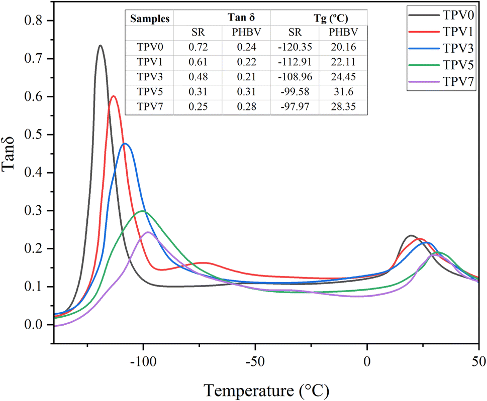 | ||
| Fig. 8 The loss tangent (tanδ) of all TPV samples. | ||
However, by increasing SMGO content, the peak of tanδ for SR monotonously decreased and became broader, showing a reduction in damping behavior. The widening Tg window shows an increment in types of chain movements at the glass transition. Furthermore, increasing SMGO leads to an increment in the Tg of the PHBV phase, meaning nanofiller networks make it harder for PHBV chains to move at the glass transition state. This observation raises the possibility of locating SMGO in PHBV or at the interface. Another interesting observation is the presence of a third peak in TPV1 at around – 25 °C related to the third phase, the interface.
Morphology
FE-SEM was used to investigate the microstructure and dispersion state of SMGO in SR/PHBV/SMGO TPV composites. The SEM images in etched and non-etched conditions are shown in (Fig. 9A–H). The dispersion state of SMGO in the matrix and its interaction with the polymer chains are essential factors that affect the final properties of the TPV. The SMGO nanoparticles were uniformly dispersed in the TPV3 and TPV5 matrix without apparent aggregation (Fig. 9B and C), and there was a preferential localization nanofiller phenomenon of SMGO in the TPV. Specifically, the SMGO was mainly distributed in the SR phase and at the interphase of SR/PHBV. The PHBV phase was represented by small holes due to etching, compared to TPV3 and TPV5. At the same time, the SR size in TPV7 was much more prominent due to SMGO aggregation in this sample (Fig. 9D). In TPV7, which contained 7 wt% SMGO, the FESEM images revealed apparent aggregation of the SMGO. However, in TPV composites with lower concentrations of SMGO, the nanoparticles were uniformly dispersed in the matrix, making a perfect network, especially in TPV5, without obvious aggregation. The distribution of SMGO in the new SR phase could lead to the formation of conductive networks at low filler content, indicating that SMGO networking significantly influences the morphology and properties of TPV composites.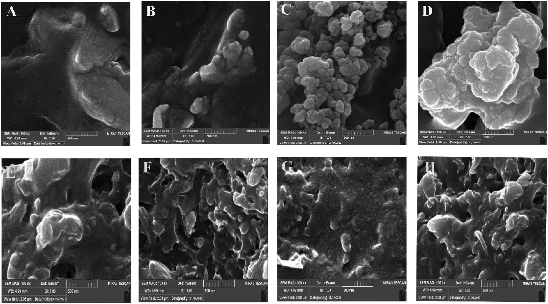 | ||
| Fig. 9 FE-SEM images of etched surfaces for different TPVs with etch surfaces ((A) TPV0, (B) TPV3, (C) TPV5, and (D) TPV7) and non-etch surfaces sample ((E) TPV0, (F) TPV3, (G) TPV5 and (H) TPV7). | ||
AFM analysis
AFM analysis was conducted to investigate the phase morphology and dispersion state of SMGO nanoparticles in the TPV nanocomposites. Fig. 10(A–D) displays the AFM images of TPV0, TPV3, TPV5, and TPV7. In these images, the darker regions represent the SR phase, while the lighter regions represent the PHBV phase. Interestingly, with increasing SMGO nanoparticle content up to 5 wt%, the cured SR domains transformed into a matrix-droplet-like phase. However, beyond that concentration, the SR domains aggregated and formed a continuous phase. Comparing the AFM micrographs shown in Fig. 10A and C, it is evident that the presence of SMGO nanoparticles had an increasing effect on reducing the size of the cured SR domains in TPV5. These results suggest that SMGO nanoparticles can act as a compatibilizer, decreasing the coalescence rate and reducing the size of the SR domains. In the nanocomposite containing 7 wt% SMGO (Fig. 10D), the larger size of the cured SR domain compared to the lower filled compositions (Fig. 10B and C) indicates nanoparticle aggregation. Additionally, it appears that the rubber droplets formed by the breakup of the SR phase under shearing stress at the beginning of dynamic vulcanization transform into rubber nanoparticles due to an increase in the degree of cross-linking.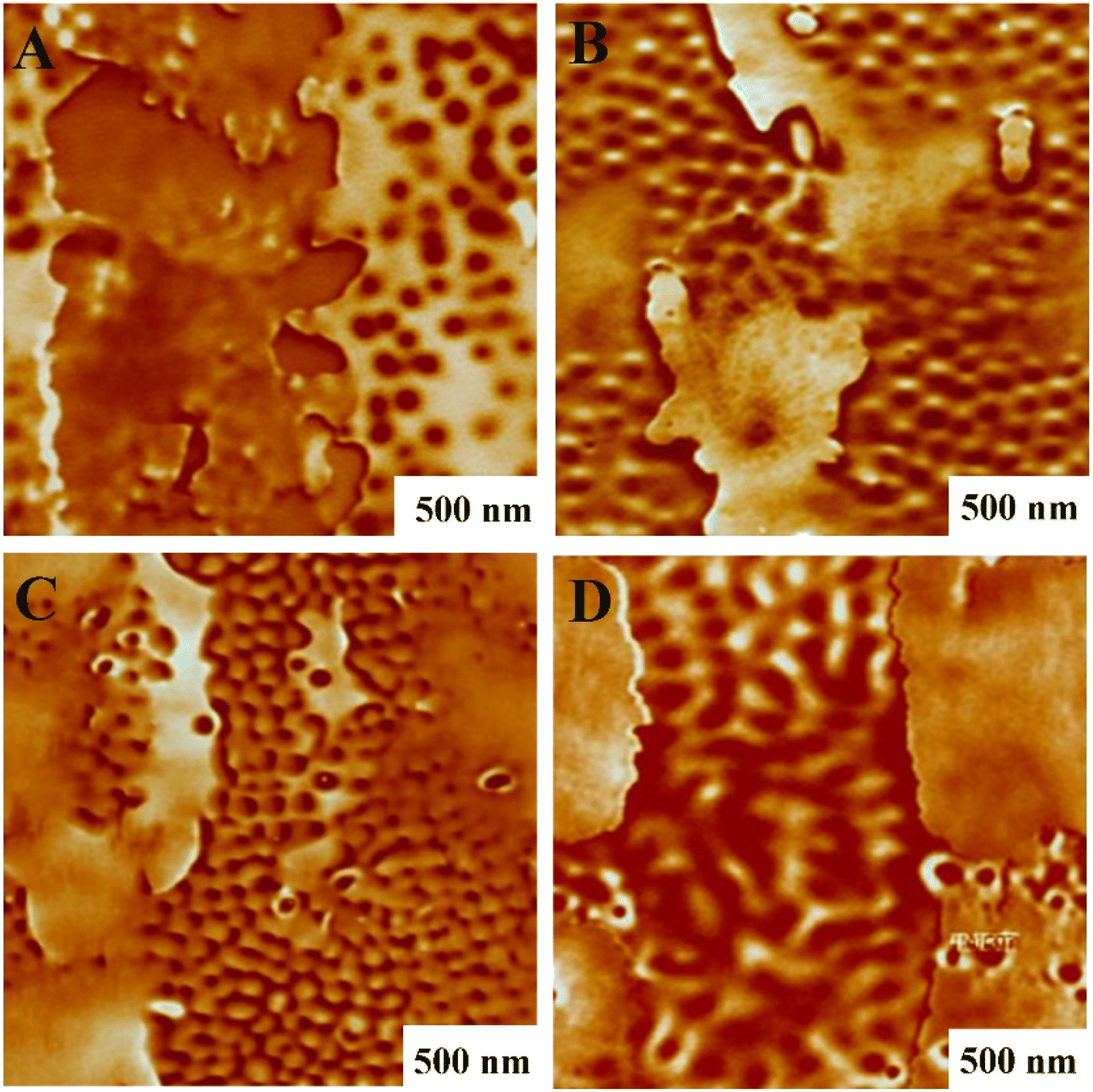 | ||
| Fig. 10 AFM phase images of TPV samples taken at different mixing times (darker regions represent SR phase and lighter regions represent PHBV phase): (A) TPV0, (B) TPV3, (C) TPV5 C, and (D) TPV7. | ||
XRD analysis
Fig. 11(A) and (B) shows the XRD pattern exhibits distinct diffraction peaks at 7.3° for GO and 4.4° for SMGO, indicating the presence of well-ordered arrangements in the material. These peaks correspond to the (001) planes, reflecting the interlayer spacing of the GO sheets. The measured basal spacing values of 1.21 nm for GO and 2.13 nm for SMGO suggest an expansion of the interlayer spacing after the attachment of PDHT. This increase can be attributed to the effective interaction between PDHT and the GO surface, leading to intercalation and expansion of the interlayer spacing. The observed weakening and shift of the (001) reflection peak in SMGO after modification with PDHT further support this interaction. The shift towards lower angles implies a possible change in the crystal structure, likely due to the introduction of PDHT molecules within the interlayer spaces of SMGO. Notably, the broader full width of the diffraction peak at the half maximum position in the SMGO XRD pattern compared to GO suggests an increase in the d-spacing between the GO sheets. This broadening can be attributed to the attachment of PDHT and the resulting introduction of disorder in the nanolayers.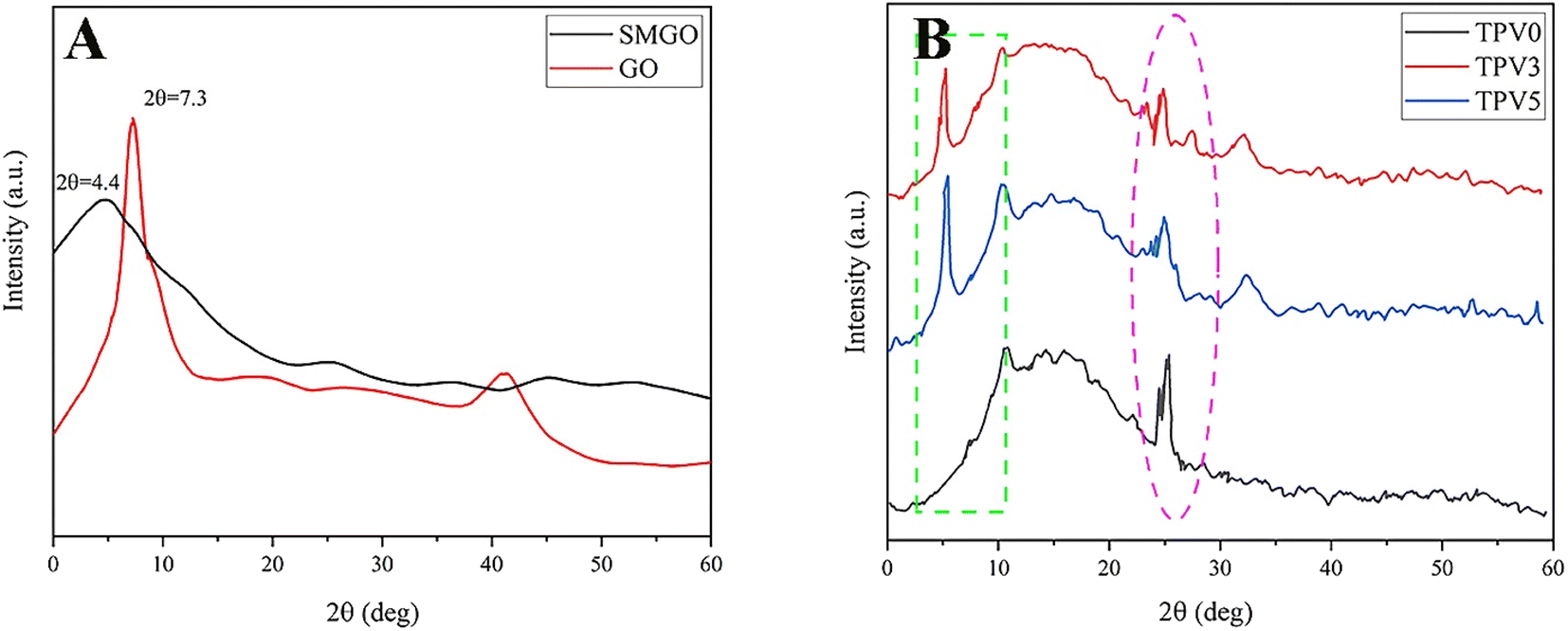 | ||
| Fig. 11 X-ray diffraction (XRD) patterns of (A) graphene oxide (GO), modified graphene oxide (SMGO), and (B) TPV samples. | ||
Moreover, the XRD patterns of TPV0, TPV3, and TPV5 samples displayed two characteristic diffraction peaks at approximately 26.5° and 4.1°, indicating the presence of the crystalline structure of PHBV and SMGO, respectively. Specifically, in the XRD patterns of TPV3 and TPV5, the presence of two prominent peaks at around 4.1° confirms the intercalation of crystalline SMGO within the TPV matrix.
Electrical property
SMGO is a conductive filler that can significantly enhance the electrical conductivity of elastomeric composites. SMGO has high electrical conductivity due to its unique 2D structure, high surface area, and many delocalized π electrons.27 SMGO particles form a conductive network through the percolation effect when incorporated into a polymer matrix. This conductive network facilitates electron transfer and increases the electrical conductivity of the composite material. Moreover, the percolation threshold, or the minimum nanofiller required to form the conductive network, is lower for SMGO than other carbon-based fillers, such as carbon nanotubes or carbon black. This makes SMGO a more efficient filler for enhancing the electrical conductivity of elastomeric composites.Fig. 12 displays that the volume conductivity of the composites was found to increase rapidly when the SMGO fillers reached a critical content, indicating the formation of a conductive network. The percolation threshold of the TPV composites was found to be around 2 wt%. In TPV7, the conductivity decreases compared to TPV5, which has a higher SMGO content. This phenomenon could be due to several factors. Firstly, the increase in the SMGO content beyond the percolation threshold can lead to the agglomeration of the SMGO particles, forming non-conductive clusters that may disrupt the conductive network. Therefore, it is possible that the higher SMGO content in TPV7 could have caused SMGO particle agglomeration, leading to a decrease in conductivity. Secondly, the high SMGO content in TPV7 could have increased the mixture's viscosity, making it difficult for the conductive network to form. The high viscosity could have hindered the mobility of the SMGO particles and prevented their uniform distribution throughout the matrix, leading to a decrease in conductivity.
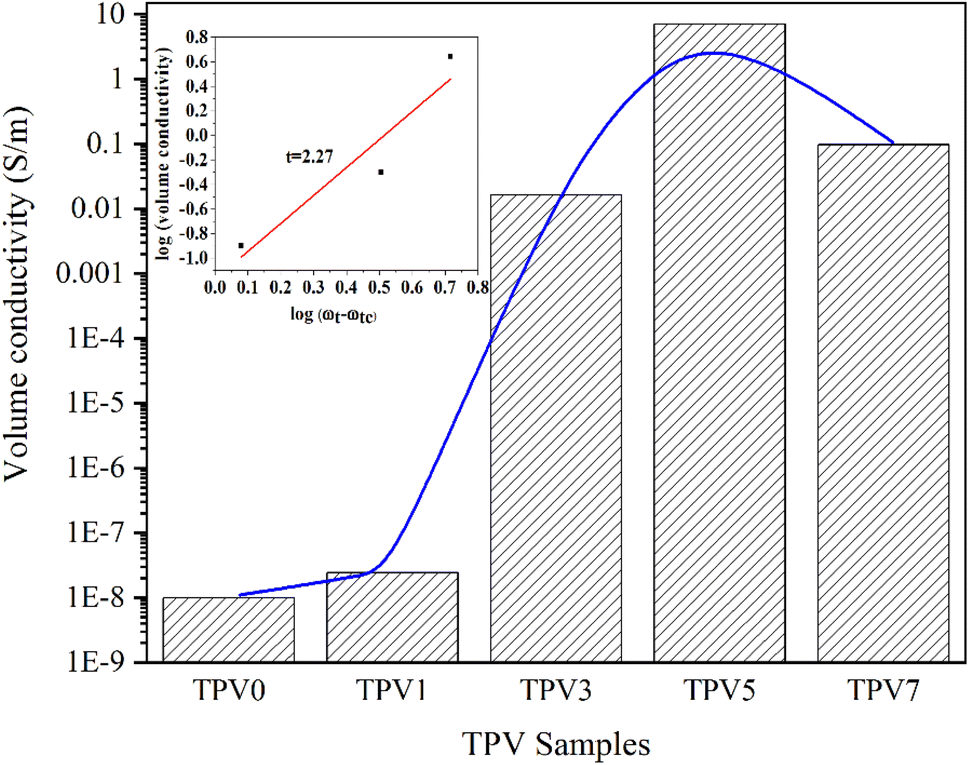 | ||
| Fig. 12 The conductivity of TPV0, TPV1, TPV3, TPV5, and TPV7 with different SMGO contents. | ||
Additionally, a significant percolation phenomenon is observed in the electrical conductivity of these composite materials.28 This means that when the SMGO content hits the percolation threshold, the electrical conductivity of the composite material dramatically increases by several orders of magnitude. The self-organized conductive composites have the highest conductivity at the same nanofiller content. The statistical percolation theory29 proposes an exponential equation to describe the correlation between the nanofiller's content and the composites' conductivity, which is given as follows:
| σ = σ0(ωt − ωtc)t |
Overall, the results suggest that the conductivity of TPVs is highly dependent on the SMGO content and its distribution in the matrix and that there is an optimal SMGO content (5 wt%) for achieving the highest conductivity.
Strain sensing behaviors
To evaluate the application prospects of the composites in strain sensors, the strain-sensing behaviors of conductive TPV nanocomposites were investigated. The gauge factor (GF) is used to evaluate the sensitivity of the sensing composites, which is defined as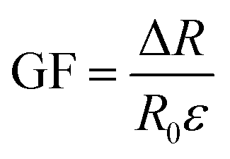 , where ΔR, R0, and ε are the resistance change, initial resistance, and engineering strain of the sample, respectively.31 GF values of the nanocomposites were 375, 83.4, and 41.7, corresponding to the nanofillers content of 5.0 wt%, 3.0 wt%, and 1.0 wt%, respectively. However, for the TPV7, the gauge factor is 166.7. There could be several reasons for this unexpected behavior. One possible reason could be the aggregation of graphene oxide (SMGO) nanoparticles at higher loading concentrations.
As shown in Fig. 13, at high concentrations, SMGO nanoparticles can form large clusters that can disrupt the conductive pathways in the material and reduce its electrical conductivity. This can lead to a decrease in the sensitivity of the sensing composites, which can result in a lower gauge factor despite the higher loading concentration. Another possible reason could be the saturation of conductive pathways in the material at higher loading concentrations. As the concentration of SMGO nanoparticles increases, the number of conductive paths in the material also increases, leading to higher sensitivity to strain and a higher gauge factor. However, at a certain point, the conductive pathways may become saturated.
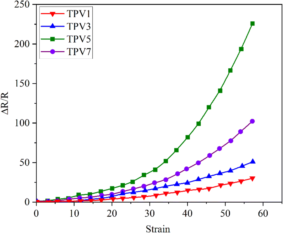 | ||
| Fig. 13 Resistance–strain relationship of conductive TPV nanocomposites under the 10 mm min−1 strain rate: different amounts of SMGO. | ||
Further increases in the loading concentration may not lead to a corresponding rise in strain or gauge factor sensitivity. It is also possible that other factors, such as the dispersion and interaction of SMGO nanoparticles within the material, could be affecting the gauge factor at higher loading concentrations. For example, suppose the SMGO nanoparticles are poorly dispersed within the material. In that case, they may be unable to form effective conductive pathways, leading to a lower gauge factor despite the higher loading concentration.
Cyclic strain-sensing behavior
The conductive pathways and morphology of composites are the primary factors that determine their piezoresistive properties. The sensitivity of strain sensors is often assessed by measuring the alteration of the electrical resistance under mechanical strain. This research aimed to determine the reliability and robustness of TPV composites by analyzing their cyclic strain-sensing behavior. To evaluate this behavior, the variation in relative resistance (ΔR/R0) was measured during loading and unloading cycles for both TPV5 and TPV7 nanocomposites, and the results are depicted in Fig. 14A–C. The study found that TPV5 and TPV7 samples showed a decreasing trend in relative resistance as the number of cycles increased. This reduction in resistivity was more noticeable at the beginning of the testing. It was due to the softening of the matrix stress from the Mullins effect and the higher contact area between the fillers.32 The repeated stretching and contracting during cyclic strain tests resulted in additional conductive pathways between the conductive particles, which decreased electrical resistance. TPV5, with an optimal SMGO content, exhibited higher resistivity than TPV7 due to constructing more agglomerated networks in the composites. | ||
| Fig. 14 Multiple stretching and releasing (100 cycles) of relative resistance (ΔR/R0) for TPV5 (A) and (B) TPV7 (C) The first ten cycles of (A) and (B). | ||
Furthermore, nanoparticles tend to localize at the interface between two phases rather than distribute within the polymer phase, mainly through the PHBV phase. Therefore, an appropriate amount of nanoparticles is necessary to balance their localization at the interface and their dispersion within the polymer phase to achieve the desired properties in nanocomposites. The aggregation of SMGO nanoparticles in a material can significantly impact its gauge factor, which measures the sensitivity of the material's electrical resistance to mechanical strain. When SMGO nanoparticles aggregate, they form large clusters, which can disrupt the conductive pathways in the material and reduce its electrical conductivity. As a result, the gauge factor of the material decreases, and its sensitivity to mechanical strain is reduced. In addition, the aggregation of SMGO nanoparticles can lead to non-uniform dispersion within the material, which can result in variations in the electrical properties of different regions. This can cause variations in the gauge factor, making it challenging to measure strain accurately in the material.
The resistivity of the composites increased when mechanical force was applied due to the change in the particle–particle distance. Subsequently, the resistivity decreased with decreasing strain, known as the positive strain effect. However, further contraction increased resistance, leading to an additional peak in each cycle, known as the negative strain effect. The competition between the destruction and reconstruction of conductive pathways is the reason behind the negative response during loading–unloading cycles. TPV7 showed a more substantial negative effect peak than TPV5, which might be attributed to the higher SMGO content. The morphological control of the conductive fillers in the TPV resulted in different piezoresistive behavior, which was investigated by studying the cyclic strain sensing behavior with varying strain amplitudes. These piezoresistive strain sensors showed the potential to detect and distinguish different movements. Finally, TPV5 was chosen to evaluate the reproducibility and stability of this material when used as a strain sensor due to its excellent strain-sensing properties. Fig. 15A–C also shows the stretching behavior of post-manufactured specimens for the TPV5 sample. (A), (B) and (C) demonstrate photographs of TPV5 composites under bending, stretching, and twisting, exhibiting their excellent stretchability. For the investigation of stretching and twisting behavior, the samples used for strain-sensing testing were hot-pressed at 180 °C and then cut into segments of either 1.5 cm or 6 cm in length after 24 hours.
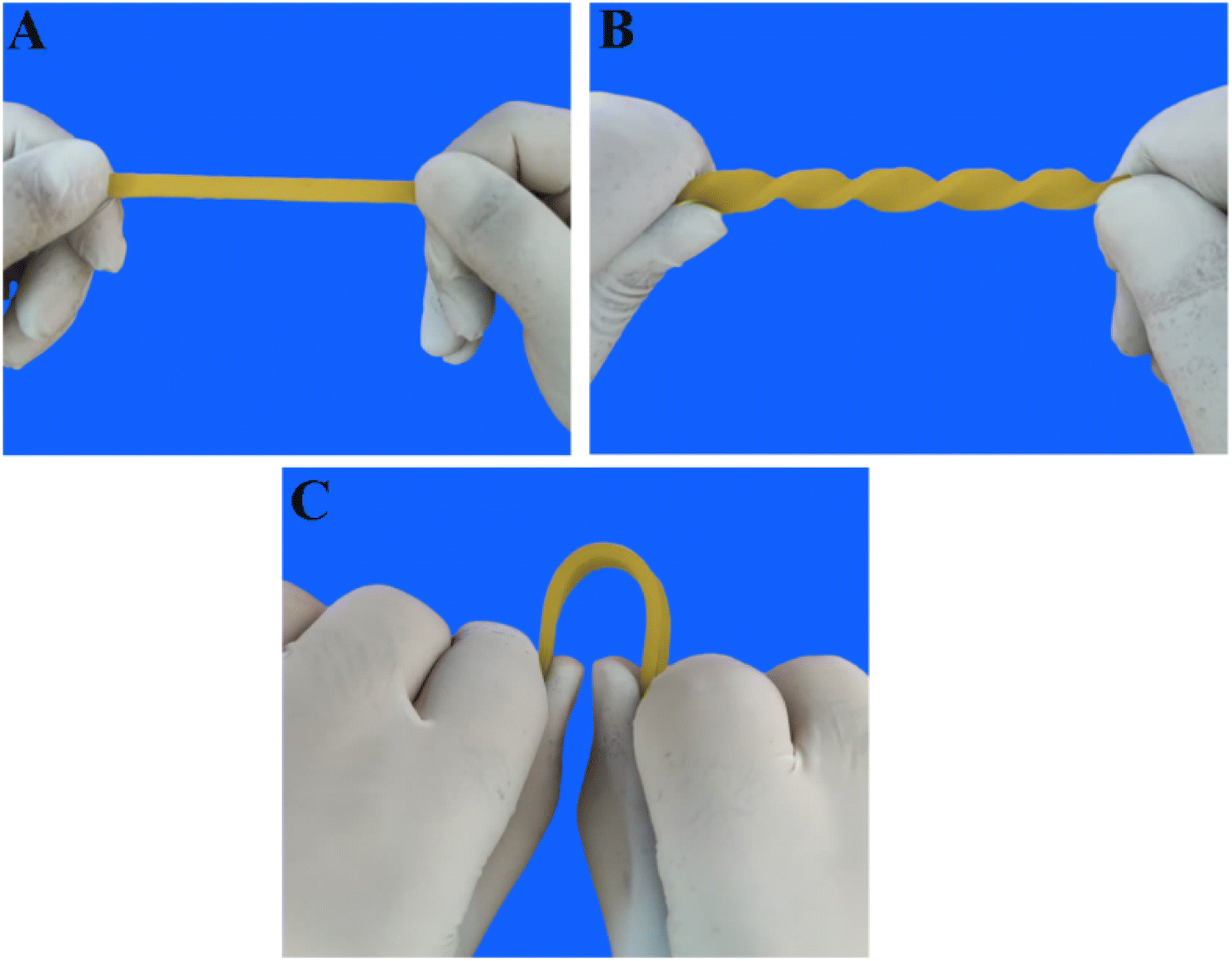 | ||
| Fig. 15 Images of post-manufactured specimens for TPV5 sample. (A), (B) and (C) demonstrate photographs of TPV5 composites under bending, stretching, and twisting, exhibiting their excellent stretchability. | ||
Thermal stability
Thermogravimetric analysis (TGA) was conducted in a nitrogen environment to check the thermostability of TPV nanocomposites. The results are shown in Fig. 16 and gathered in Table 2. The onset of thermal degradation is around 250 °C for TPV0, which increases with increasing the content of SMGO. The improved thermal stability observed in TPV nanocomposites with the addition of SMGO can be attributed to two possible mechanisms. Firstly, the shielding effect of SMGO fillers plays a crucial role in improving the thermal stability of the composite. SMGO particles create a network structure in the composite that can retard the onset of thermal degradation, as well as inhibit the degradation of the polymer matrix by creating a physical barrier between the polymer chains and the environment. The high aspect ratio and large surface area of SMGO can also effectively absorb and dissipate thermal energy, reducing the overall thermal degradation rate of the composite. Secondly, SMGO can act as a nucleating agent during the crystallization process of the polymer matrix. The presence of SMGO can induce the formation of smaller and more uniform crystallites, which can improve the thermal stability of the composite by reducing the potential for thermal degradation through chain scission or crosslinking reactions.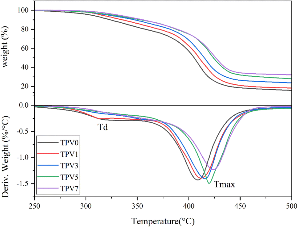 | ||
| Fig. 16 (Upper) TGA thermograms and (Lower1) derivative graphs (DTG) of five TPV nanocomposites. DTG, TGA, thermogravimetric analysis. | ||
| Sample ID | Td (°C) | Tmax (°C) |
|---|---|---|
| TPV0 | 310 | 405 |
| TPV1 | 315 | 410 |
| TPV3 | 320 | 420 |
| TPV5 | 325 | 420 |
| TPV7 | 320 | 425 |
TPV5 has the onset of degradation around 275 °C. The shielding phenomenon is more pronounced where SMGO particles have good dispersion throughout the sample, and the presence of perfect networks in TPV5 is again perceived from TGA results. The 5% loss temperature (T5%) and the 50% loss temperature (T50%) are also enhanced by increasing nanofillers, especially in TPV5. Furthermore, TPV5 has the highest weight residue after finishing the test. We believe that although TPV7 has more nanofiller content, in TPV5, there must be a good dispersion, and more SR chains wet the SMGO. Therefore, the perfect network would remain till the end of degradation.
Based on DTGA curves, TPV0 and TPV1 show two-step degradation, where the first degradation peak around 315, and 320 °C, respectively, would be related to the degradation of the PHBV phase. For TPV5 and TPV7, a slight degradation peak can also be detected around 360 °C, another indicator of the shielding mechanism, which retard and hinder the PHBV chain from degrading. The other prominent degradation peak is SR degradation, around 410–425 °C for all samples. Here again, it is confirmed that by increasing the nanofiller content, the peak of degradation shifts to a higher temperature, and the peak height also reduced considerably in the TPV5 sample, which again confirms the presence of perfect dispersion and wetting of SR chains with nanofillers and the presence of perfect networks in this sample.
The thermal degradation temperature (Td) is the temperature at which the material starts to degrade. In contrast, the maximum degradation temperature (Tmax) is the temperature at which the maximum rate of degradation occurs. Based on the results, we can see that increasing the SMGO content in the TPV nanocomposites generally leads to an increase in both Td and Tmax. This indicates that adding SMGO improves the thermal stability of the TPV nanocomposites. The rise in Td and Tmax can be attributed to the presence of SMGO, which acts as a thermal stabilizer by forming a protective layer around the polymer matrix, hindering the escape of volatile products and reducing the rate of degradation. The intense interaction between SMGO and the polymer matrix can also delay the onset of thermal degradation, resulting in a higher Td value.
Moreover, the increase in Tmax with increasing SMGO content can be explained by the fact that SMGO can absorb a significant amount of heat during thermal degradation, and the absorbed heat is released slowly, thus reducing the peak degradation temperature. This results in a broader degradation peak with a lower peak height, consistent with the results provided. Indeed, the results suggest that SMGO can effectively improve the thermal stability of TPV nanocomposites, making them more suitable for high-temperature applications.
Conclusions
The extremely stretchy and sensitive strain sensors with a unique formulation based on PHBV/SR/GMGO conductive network were created using a straightforward construction method we presented. The design of this TPV significantly improved the electrical characteristics and lowered the limit for electrical percolation in the composites. The optimum manufactured strain sensor (TPV5) also had outstanding stretchability, sensitivity (gauge factor, 375), and repeatability, which made it appropriate for detecting human body motion under much strain. The strain sensors are made possible with good performances thanks to the strong assembly fueled by electrostatic contacts between PHBV/SR and SMGO particles and the volume-extrusion effect originating from the SR phases. With these characteristics, the strain sensor based on Geelastomer composites may find use in stretchy electronics, physical motion detection, and other relevant fields.Furthermore, we have demonstrated that adding SMGO at a concentration of 5 weight percent results in a more uniform dispersion and creates an SMGO network, significantly enhancing the composite's tensile strength and elongation at break. Our research has also shown that the dynamic vulcanization and mixing method used to create TPV nanocomposites can substantially influence their shape. We have shown explicitly that adding SMGO nanoparticles causes a more uniform dispersion of the matrix droplet in the TPVs, contributing to the composites' improved mechanical and electrical characteristics. In addition, our research has demonstrated that dynamic vulcanized PHBV/SR/SMGO composites have unique electrical and piezoresistive characteristics. With adjustable positive piezoresistivity and a gauge factor of 375, the TPV5 exhibits excellent electrical and mechanical properties and superior sensing responsiveness. Our findings highlight the significance of managing particle size, distribution, and interparticle interactions to reduce the Payne effect and enhance the mechanical characteristics of filled TPV nanocomposites. Future work may focus on improving the processing conditions for particular applications and investigating the full potential of SMGO-based TPVs in other materials science and technology fields. Our work highlights the promise of nanofiller-based composites for various applications, including creating high-performance TPV materials for diverse biological applications, and contributes significantly to the area.
Author contributions
A. Moshkriz conducted the laboratory experiments, and A. Moshkriz and Z. Shahroodi conducted the data collection and analysis and contributed to manuscript writing. R. Darvishi (corresponding author) conceptualized the study, provided guidance throughout the research process, and wrote the manuscript. All authors reviewed and approved the final version of the manuscript.Conflicts of interest
We have no financial, personal, or professional relationships that could potentially bias our work or be perceived as a conflict of interest. We have received no funding or grants from any company or organization interested in this research. All authors have reviewed and approved the final version of the manuscript.References
- A. Moshkriz, R. Darvishi, A. Barati, M. Askari and S. Mosleh, Mater. Today Commun., 2021, 26, 102046 CrossRef CAS.
- S. Dutta, S. Sengupta, J. Chanda, A. Das, S. Wiessner, S. S. Ray and A. Bandyopadhyay, Polym. Test., 2020, 83, 106374 CrossRef CAS.
- S. Paran, G. Naderi, S. Shokoohi, J. Ebadati and C. Dubois, J. Polym. Environ., 2019, 27, 2017–2026 CrossRef CAS.
- Z. Shahroodi and A. A. Katbab, Polym. Eng. Sci., 2022, 62, 1485–1495 CrossRef CAS.
- A. Moshkriz and R. Darvishi, Polym. Polym. Compos., 2022, 30, 1–11 Search PubMed.
- Y. Ding, J. Yang, C. R. Tolle and Z. Zhu, RSC Adv., 2016, 6, 79114–79120 RSC.
- P. Pujar, K. Jagadeeshkumar, M. Naqi, S. Gandla, H. Cho, S. Jung, H. Cho, J. Kalathi, S. Kim and J. Kang, 2017.
- X. Li, H. Kang, Q. Luo and J. Shen, RSC Adv., 2022, 12, 9534–9542 RSC.
- Y. Wang, K. Chen, C. Xu and Y. Chen, J. Phys. Chem. B, 2015, 119, 12138–12146 CrossRef CAS PubMed.
- V. Kumar, M. N. Alam and S. S. Park, J. Polym. Res., 2022, 29, 251 CrossRef CAS.
- J. Fan, M. Yan, J. Huang, L. Cao and Y. Chen, Ind. Eng. Chem. Res., 2019, 58, 15199–15208 CrossRef CAS.
- M. I. Ibrahim, D. Alsafadi, K. A. Alamry and M. A. Hussein, J. Polym. Environ., 2021, 29, 1010–1030 CrossRef CAS.
- G. G. Jang, N. A. Nguyen, C. C. Bowland, H. C. Ho, J. K. Keum and A. K. Naskar, Compos. Sci. Technol., 2020, 199, 108352 CrossRef CAS.
- B. Thongnuanchan, W. Nantayos, N. Lopattananon, S. Rattanapan, A. Thitithammawong and C. Nakason, J. Polym. Environ., 2019, 27, 1807–1820 CrossRef CAS.
- Y. Zheng, Y. Li, K. Dai, Y. Wang, G. Zheng, C. Liu and C. Shen, Compos. Sci. Technol., 2018, 156, 276–286 CrossRef CAS.
- W. Wang, S. Yang, K. Ding, L. Jiao, J. Yan, W. Zhao, Y. Ma, T. Wang, B. Cheng and Y. Ni, Chem. Eng. J., 2021, 425, 129949 CrossRef CAS.
- C. M. Palicpic, R. Khadka and J.-H. Yim, ACS Appl. Polym. Mater., 2022, 4, 2614–2625 CrossRef CAS.
- G. Santamaría-Juárez, E. Gómez-Barojas, E. Quiroga-González, E. Sánchez-Mora, M. Quintana-Ruiz and J. D. Santamaría-Juárez, Mater. Res. Express, 2020, 6, 125631 CrossRef.
- J. Zhang, S. Liang, L. Yu, A. Ladegaard Skov, H. M. Etmimi, P. E. Mallon, A. Adronov and M. A. Brook, J. Polym. Sci., Part A: Polym. Chem., 2016, 54, 2379–2385 CrossRef CAS.
- S. Salaeh, A. Das, K. W. Stöckelhuber and S. Wießner, Composites, Part A, 2020, 130, 105763 CrossRef CAS.
- B. Zhang, R. Li, J. Luo, Y. Chen, H. Zou and M. Liang, Polym. Bull., 2018, 75, 2105–2124 CrossRef CAS.
- M. J. Azizl, M. Barghamadi, K. Rezaeeparto, M. Mokhtary and S. Parham, J. Polym. Res., 2021, 28, 1–21 CrossRef.
- Y.-y. Shi, J.-h. Yang, T. Huang, N. Zhang, C. Chen and Y. Wang, Composites, Part B, 2013, 55, 463–469 CrossRef CAS.
- S. Akram, Y. Yang, X. Zhong, S. Bhutta, G. Wu, J. Castellon and K. Zhou, IEEE Trans. Dielectr. Electr. Insul., 2018, 25, 1461–1469 CAS.
- M. Barghamadi, M. Karrabi, M. H. R. Ghoreishy and S. Mohammadian-Gezaz, J. Appl. Polym. Sci., 2019, 136, 47550 CrossRef.
- S. Qi, M. Yu, J. Fu, M. Zhu, Y. Xie and W. Li, Soft Matter, 2018, 14, 8521–8528 RSC.
- J. Yang, H. Miao, Y. Wei, W. Li and Y. Zhu, Appl. Catal., B, 2019, 240, 225–233 CrossRef CAS.
- M. Saleem, M. S. Butt, A. Maqbool, M. A. Umer, M. Shahid, F. Javaid, R. A. Malik, H. Jabbar, H. M. W. Khalil and L. D. Hwan, J. Alloys Compd., 2020, 822, 153525 CrossRef CAS.
- S. Azizi, E. David, M. F. Fréchette, P. Nguyen-Tri and C. M. Ouellet-Plamondon, J. Appl. Polym. Sci., 2019, 136, 47043 CrossRef.
- M. Jayalakshmy and R. K. Mishra, Carbon-Based Nanofillers and Their Rubber Nanocomposites, Elsevier, 2019, pp. 441–472 Search PubMed.
- M. Zhu, N. Inomata, N. Adachi, A. Sakurai, M. Nomura and T. Ono, IEEE Sens. J., 2019, 19, 3626–3632 CAS.
- M. Qian, B. Zou, Z. Chen, W. Huang, X. Wang, B. Tang, Q. Liu and Y. Zhu, Polymers, 2021, 13, 2284 CrossRef CAS PubMed.
Footnote |
| † Electronic supplementary information (ESI) available. See DOI: https://doi.org/10.1039/d3ra02940a |
| This journal is © The Royal Society of Chemistry 2023 |