 Open Access Article
Fabrication and characterization of mesoporous yolk–shell nanocomposites as an effective reusable heterogeneous base catalyst for the synthesis of ortho-aminocarbonitrile tetrahydronaphthalenes†
Mahsa Khorasani and
Hossein Naeimi
 *
*
Department of Organic Chemistry, Faculty of Chemistry, University of Kashan, Kashan, 87317-51167, Iran. E-mail: Naeimi@kashanu.ac.ir; Fax: +983155912397; Tel: +98-31-55912388
First published on 20th June 2023
Abstract
Mesoporous yolk–shell nanocomposites (MYSNs) were loaded with a mobile CaMg core inside the silica shell. CaMg@MYS nanocomposites have been effectively prepared inside the inner cavity of a novel structure that consists of hollow mesoporous silica spheres. Tetraethyl orthosilicate (TEOS) and an amount of cetyltrimethylammonium bromide (CTAB) are coated on the carbon spheres used as a hard template in the multi-step synthetic procedure. In this method, the target products were obtained in high to excellent yields between 87–96% and quick response times between 10–20 minutes under mild conditions. The CaMg@MYS catalyst shows promise as an efficient and reusable catalyst in multicomponent processes. The CaMg@MYS multi-yolk spheres compared to metal oxide nanostructures indicated both high catalytic performance and a significant factor as a novelty. To identify each product, FT-IR, 1H NMR, and melting point techniques were applied. Also, in order to characterize the prepared catalysts, FT-IR, XRD, FE-SEM, EDS, elemental mapping, and HR-TEM techniques were applied.
1. Introduction
Hollow nanostructures as nano-sized materials have always been an attractive and practical topic in engineering and basic sciences. They have low density, high surface-to-volume ratio, and abundant internal space, and have a high capacity to accept guest species due to their high mass-to-volume ratio.1–8Considering that hollow nanostructures play the role of catalysts,9 they can provide internal and external surfaces for reaction sites. Hollow nanostructures have also been created in prismatic, cubic, and polyhedral shapes, in addition to the more typical tubular and spherical ones. Supercapacitors, lithium–sulfur batteries and photoelectrochemical cells can all be made and prepared using hollow nanostructures.10–13 Yolk–shell nanoparticles are known by a variety of names including nanorattles, movable core/shell, yolk/shell and core/shell with a hollow interior.14 Recently, mesoporous silica spheres that have been combined with various metals to form yolk–shell nanostructures have caught the attention of chemists.15 A wide range of hard templating methods, including carbon,16 polymers, silica,17 metal-based compounds and some natural materials have been developed to prepare hollow nanostructures.18
The unique properties of yolk–shell nanostructures are derived from the active core, hollow shell, and empty regions of yolk–shell nanoparticles. For the preparation of yolk–shell structures, a sacrificial hard or soft template is usually used to cover the core, and then the cover is used to form the desired shell; then, the template is removed to create a cavity. Sometimes the active catalytic species may be placed inside the hollow structures, and by increasing the stability, the catalytic performance is enhanced.19 So far, many methods have been proposed for the synthesis of nanostructures.
In this article, we discuss the hard templating method. In yolk@shell structures, there is a hollow cavity between the core and the shell. The cavity makes the outer surface of the core defined. Core–shell catalysts may have lower activity than similar yolk@shell catalysts because yolk@shell catalysts are available and have many active sites. These types of hollow structures transfer reactants and products faster by protecting the shell. The shell protects the core by limiting access to toxins. The shell may be too thin to limit transmission.20
Heterocyclic structures are common in the natural compounds that are bioactive. More than half of all organic chemicals are heterocyclic compounds. One of the most significant ring compounds in organic chemistry is tetrahydronaphthalene. The tetrahydronaphthalene derivatives have gained a lot of attention over the years as a well-known organic synthesis intermediate with diverse uses.21,22 They have been employed a lot in the synthesis of several heterocyclic compounds.23,24 Numerous procedures have lately been devised as a result of the interest shown by many organic chemists in the ortho-aminocarbonitrile tetrahydronaphthalene derivatives. The ortho-aminocarbonitrile derivatives are useful starting points for the synthesis of their corresponding dicyanoanilines because of their optical characteristics.25–27
In this research, in continuation of ongoing our team work on the catalytic reactions,28–31 we hope to prepare a new hollow yolk–shell nanocomposites, CaMg@MYS, and using as a heterogeneous base nanocatalyst in organic reaction. Here, we developed a manufacturable hard templating method to create CaMg@MYS nanocomposites. The obtained composites have the correct arrangement of cores and shells as well as multifunctional properties. Yoke–shell porous silica nanocomposites with distinct spatially dispersed base sites showed improved catalytic activity in multicomponent processes compared to their core–shell counterparts. Furthermore, these results pave the way to create core–shell nanocomposites with stable properties. This catalyst was used for synthesis of ortho-aminocarbonitrile tetrahydronaphthalenes from the multicomponent reaction of an aromatic aldehyde and cyclohexanone under mild condition. The novelty and advantages of this work are the use of available metals such as calcium and magnesium, simplicity of the reaction and work up and its cost-effectiveness compared to other mineral-based catalysts, high yield of products and low reaction times.
2. Experimental
2.1. Materials and apparatus
It was used high purity, commercially available reagents from Merck and Sigma-Aldrich chemical companies. All of the reagents were used without any further purification. If needed, the products were purified via a thin-layer chromatography process to obtain the corresponding products in 87–96% yields. IR spectra were recorded on a Nicolet FT-IR spectrophotometer, using KBr pellets as a reference. 1H NMR spectra were recorded in DMSO-d6 on a Bruker DRX-400 spectrometer with TMS as an internal reference. The reaction mixture was homogenized using a BANDELIN ultrasonic HD 3200 with probe model KE76. An X'Pert Pro (Philips) apparatus with 1.54 Å wavelengths and Cu anode material was used to create XRD patterns. Zeiss' 15 kV accelerating voltage was used to perform field emission scanning electron microscopy (FE-SEM) of nanoparticles. High Resolution Transmission Electron Microscopy (HR-TEM) was prepared by a FEI Tecnai F20 at 200 kV instrument. Yanagimoto micro melting point equipment was used to measure melting points.2.2. General procedure for preparation of CaMg@MYS
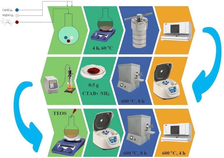
To prepare the CaMg@MYS, in the first step, 2 mL of calcium nitrate (1 M), 2 mL of magnesium nitrate (1 M), and 25 mL of glucose solution (1 M) were transferred to the 250 round-bottomed flask and stirred for 4 h at 60 °C. Next, the reaction mixture was placed in a Teflon-lined stainless-steel autoclave at 170 °C for 4 h. The obtained sediments were separated by centrifugation, washed three times with distilled water and ethanol, and dried at 70 °C. The obtained carbon nanospheres were transferred to the furnace under argon gas flow and heat at 600 °C for 4 hours. Then 0.5 g of obtained carbon nanospheres and 0.25 g of CTAB were added to 25 mL aqueous ammonia (34%). The solution was sonicated for 15 min at 35 W. The reaction mixture was refluxed under nitrogen gas flow for 8 hours, and 0.24 mL of TEOS was added drop by drop. The obtained sediments were separated by centrifugation, washed three times with distilled water and ethanol, and dried at 70 °C. Finally, the nanoparticles calcinated in argon gas flow and air atmosphere at 600 °C for 4 h (Fig. 1).2.3. General procedure for the synthesis of ortho-aminocarbonitrile tetrahydro-naphthalenes
In a round-bottomed flask equipped with a stirrer, cyclohexanon (1 mmol), aromatic aldehydes (1 mmol), malononitrile (2 mmol), and CaMg@MYS catalyst (5 mg) were stirred in 5 mL ethanol under 70 °C. The progress of the reaction was monitored by Thin-layer chromatography (TLC). Following the completion of the reaction, the precipitate was separated from the filtrate with filter paper and washed with ethanol. The precipitate was then dissolved in ethyl acetate to separate the catalyst. For reuse, the catalyst was washed with acetone and dried at 80 °C. A pure product was obtained by evaporating the solvent under reduced pressure and drying it for 12 h at 60 °C.The obtained products were characterized by spectroscopic data such as; FT-IR, 1H NMR and the melting points of known compounds are compared with authentic samples;32–36,39,41 that the related data are reported to ESI.†
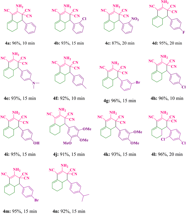
2.3.1.1 2-Amino-4-phenyl-4a,5,6,7-tetrahydronaphthalene-1,3,3(4H)-tricarbonitrile (4a). White solid; m.p.: 255–256 °C, (m.p.: 255–257 °C) Lit.,32 IR (KBr, ν, cm−1): 3417, 3338, 2931, 2865, 2208, 1646, 1599, 1496, 1391, 1275, 1037, 713, 579; 1H NMR (400 MHz, DMSO-d6) (δ, ppm): 7.48–7.62 (m, 2H), 7.43 (s, 3H), 7.38 (s, 2H), 5.73 (t, 1H), 3.54 (d, J = 12.0 Hz, 1H), 2.72–2.88 (m, 1H), 2.14–2.25 (m, 1H), 1.98–2.12 (m, 1H), 1.62–1.72 (m, 1H), 1.38–1.52 (m, 2H), 0.81–0.91 (m, 1H).
2.3.1.2 2-Amino-4-(2-chlorophenyl)-4a,5,6,7-tetrahydronaphthalene-1,3,3(4H)-tricarbonitrile (4b). White solid; m.p.: 282–284 °C, (m.p.: 271–272 °C) Lit.,33 IR (KBr, ν, cm−1): 3445, 3355, 2945, 2853, 2216, 1624, 1441, 1390, 1272, 1041, 749, 510; 1H NMR (400 MHz, DMSO-d6) (δ, ppm): 7.79 (dd, J = 8.0 Hz, 1H), 7.62 (d, J = 8.0 Hz, 1H), 7.48–7.58 (m, 2H), 7.45 (s, 2H), 5.77 (s, 1H), 3.88 (d, J = 12.0 Hz, 1H), 2.80–2.92 (m, 1H), 2.02–2.24 (m, 2H), 1.62–1.70 (m, 1H), 1.33–1.50 (m, 2H), 0.75–0.89 (m, 1H).
2.3.1.3 2-Amino-4-(2-nitrophenyl)-4a,5,6,7-tetrahydronaphthalene-1,3,3(4H)-tricarbonitrile (4c). Cream solid; m.p.: 244–246 °C, (m.p.: 245–247 °C) Lit.,39 IR (KBr, ν, cm−1): 3444, 3356, 2860, 2215, 1626, 1525, 1443, 1354, 1269, 1045, 726, 507; 1H NMR (400 MHz, DMSO-d6) (δ, ppm): 8.09 (d, J = 8.0 Hz, 1H), 8.02 (d, J = 8.0 Hz 1H), 7.92 (t, 1H), 7.75 (t, 1H), 7.45 (s, 2H), 5.79 (s, 1H), 4.07 (d, J = 12 Hz, 1H), 2.96–3.08 (m, 1H), 2.04–2.26 (m, 2H), 1.69–1.73 (m, 1H), 1.45–1.52 (m, 2H), 0.98–1.07 (m, 1H).
3. Results and discussion
3.1. Preparation and characterization of catalyst
First, using a hydrothermal method to carbonize the glucose, it was created the microsphere carbon core, which includes calcium and magnesium nanoparticles. Instead of hollow spheres, calcium and magnesium attached to the hydroxyl group create uniform nanoparticles. Then, it was coated the silica as a hard template, which placed under argon gas flow at 600 °C for four hours. The TEOS was added to the CaMg@C nanospheres, to form the dense SiO2. Then, the CTAB added to a layer of silica on a carbon sphere containing Ca and Mg nanoparticles, to produce hollow mesoporous SiO2. In the second process, the hollow mesoporous SiO2 was placed under argon gas flow at 600 °C for four hours. Finally, the carbon sphere and CTAB are removed after four hours at 600 °C under air exposure. It was created a uniform mesoporous silica sphere with calcium and magnesium nanoparticles (CaMg@MYS) (Scheme 1).The CaMg@MYS nanocatalyst was identified using a variety of techniques including FT-IR, XRD, FE-SEM, mapping, EDS and HR-TEM.
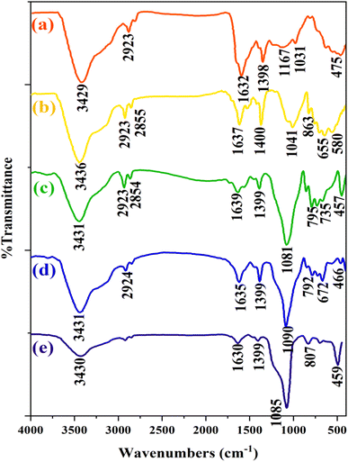
The FT-IR spectra of CaMg@MYS are shown in Fig. 2. As can be seen in this figure, FT-IR spectrum of CaMg@C nanospheres show absorption bands at 3429 and 1632 cm−1 related to OH stretching and bending, respectively. Additionally, the absorption band at 1398 cm−1 related to the CH2 bending. Also, absorption band at 1031 cm−1 related to the C–O bond stretching. The most likely, the absorption band of 1166 cm−1 is related to the carbon–carbon bond, to show the presence of a carbon sphere, which indicated in the Fig. 2a. In Fig. 2b, the spectrum of the CaMg@C nanospheres after placing in the argon furnace is shown in which observed any changes and confirmd the presence of the carbon sphere. Furthermore, the Mg–O and Ca–O stretching vibrational modes are appeared to the absorption bands at 655 cm−1 and 580 cm−1, respectively. In Fig. 2c which corresponds to the addition of TEOS and CTAB steps, the absorption bands at 795 cm−1 and 1081 cm−1 are depicted. These bands are attributed to the symmetrical and asymmetrical stretching vibrations of the Si–O–Si bands, respectively. In Fig. 2d, the CTAB group was removed from the catalyst by calcination as evidenced by the decrease in the strength of the absorption band linked to the C–H stretching vibrations in the range of 2924 cm−1 and 2854 cm−1. Finally, as shown in Fig. 2e, the presence of weakness of the absorption band at 3430, 1630, and 1399 cm−1 confirms the removal of CTAB and glucose. The presence of 1090 and 792 cm−1 absorption bands proves the existence of the Si–O–Si bond.
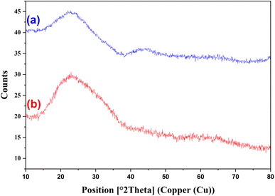
The X-ray diffraction (XRD) for the CaMg@MYS hollow nanosphere after and before putting under argon gas flow was provided and the regarding patterns are shown in Fig. 3. The peaks at 2θ values of 15–35 in pattern a can be attributed to amorphous SiO2.
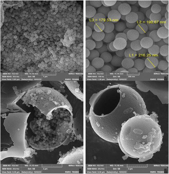
The FE-SEM images of CaMg@MYS are indicated in Fig. 4. The smooth-surfaced carbon spheres with spherical morphology are depicted by using FE-SEM in this figure. These carbon spheres have many hydroxyl groups functionalized onto them as a result of the non- or partial dehydration of carbohydrates which supports the high capacity attachment of metal ions.37 In actuality, using an electron beam to scan the surface of the material is one way to create images with a microscope. In compared with light photons, the electrons have shorter wavelengths which improves data clarity, separation power and suitability. A carbon microsphere containing an uniform distribution of calcium and magnesium nanoparticles demonstrated by FE-SEM. Through scanning electron microscopy (FE-SEM) analysis, the size and morphology of the nanoparticles were determined. As a result of the integration of these particles in carbon microspheres, the average size of the holes is 43 nm. The hollow interior of the partially shattered particle was also plainly seen in the FE-SEM image (Fig. 4).
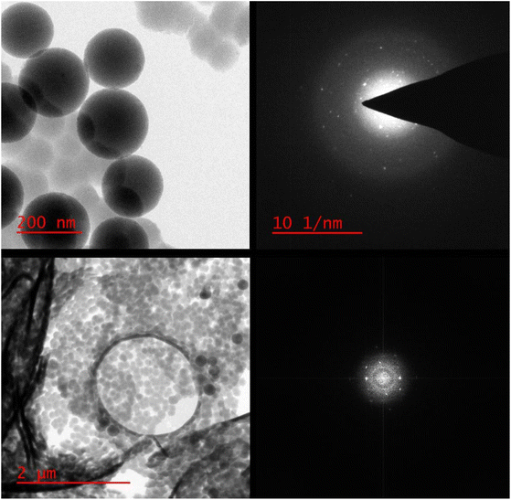
As can be seen in the high-resolution transmission electron microscopy (HR-TEM) photographs in Fig. 5, the generated calcium and magnesium nanoparticles were encased in a porous SiO2 shell.
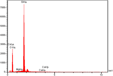
The quantitative analysis results for the CaMg@MYS were acquired using the energy dispersive spectroscopy (EDS) technique. The related peaks appearing to confirm the presence of O (58.3%), Mg (0.06%), Si (41.87%), and Ca (0.04%) signals in the structure of this carbon nanosphere (Fig. 6).
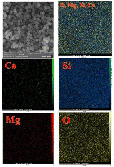
The elemental mapping study for the CaMg@MYS is shown in Fig. 7. This figure indicates that the calcium and magnesium nanoparticles are homogeneously and uniformly distributed throughout the silica nanospheres and also confirms the presence of oxygen and silicon atoms in the nanocatalyst.
3.2. Investigation of catalytic activity of the CaMg@MYS
At first time, in order to determine the best conditions for the reactions, the different catalyst amounts, solvents and reaction temperatures were studied. To begin, the model reaction of cyclohexanone, malononitrile, and benzaldehyde was chosen to identify the best parameters. The regarding results were compiled in Table 1S (see ESI† file). To determine the ideal reaction conditions, the reaction was also carried out in a variety of solvents, including ethanol, toluene, DMSO, methanol, water, water/ethanol, and acetonitrile. The reaction in the presence of 10 mg CaMg@MYS catalyst in toluene solvent under reflux condition was resulted the lowest amount of product (ESI: Table 1S,† entry 3). If the amount of catalyst was reduced to 5 mg at 10 minutes in ethanol solvent under reflux condition, a 96% product yield was observed (ESI: Table 1S,† entry 9). By increasing the amount of catalyst to 8 and 10 mg under reflux conditions with ethanol as the solvent, no change in reaction efficiency was observed (ESI: Table 1S,† entry 10,11).The reaction conditions were established after the reaction was optimized based on the different solvents, catalyst amounts and temperatures. In ascertain and limitation of this protocol, the reaction of cyclohexanone (1 mmol), aromatic aldehydes (1 mmol), and malononitrile (2 mmol) was carried out according to the general experimental procedure under optimized conditions. The corresponding products and their results are summarized in Table 1. As a result, several ortho-aminocarbonitrile tetrahydronaphthalene derivatives were produced between 87–96% yield at reaction times between 10–20 minutes. Furthermore, by the usage of aromatic aldehydes including both various electron withdrawing and electron donating substituents in the reaction, the related products are achieved in high to excellent yields.
| a Reaction conditions: cyclohexanone (1 mmol), malononitrile (2 mmol), benzaldehyde (1 mmol), CaMg@MYS (5 mg), ethanol solvent (5 mL), reflux. |
|---|
 |
 |
In this research, the preparation of ortho-aminocarbonitrile tetrahydronaphthalene derivatives by using various catalysts have been studied (Table 2). The present reaction using 5 mg of CaMg@MYS as a reactive heterogeneous catalyst, the best outcome was achieved at 10 minutes with an efficiency of 96% product yield. While, this reaction by using the previously reported work resulted the ortho-aminocarbonitrile tetrahydronaphthalenes as a target product in lower yields and longer reaction times (Table 2, entry 5 vs. entries 1–4).
3.3. Proposed reaction mechanism for synthesis of ortho-aminocarbonitrile tetrahydro-naphthalene derivatives
Scheme 2 depicts a possible chemical pathway for the production of tetrahydronaphthalene. Firstly, the intermediate B is created by the reaction of cyclohexanone and malononitrile. The basic catalyst then separates the acidic hydrogen from a subsequent mole of malononitrile and treated with aldehyde to produce intermediate D. Intermediate B is transformed into intermediate C through tautomerization, and the intermediates C and D are then combined to form intermediate E through the Diels–Alder reaction which ultimately results in the desired product F after removal of the hydrogen using a base catalyst. In order to investigate the reaction via free radical reaction mechanism, the 2,2,6,6-tetramethyl-1-piperidinyloxy (TEMPO) was added to a sample reaction as a free radical scavenger. The result was indicated that the reaction was not restrained. Thus, it is confirmed that the reaction was not proceeded via free radical reaction mechanism.42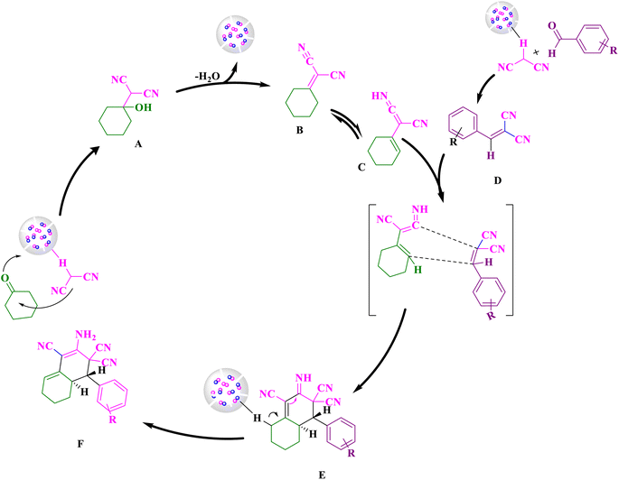 | ||
| Scheme 2 Suggestion reaction mechanism pathway for the synthesis of ortho-aminocarbonitrile tetrahydronaphthalene. | ||
3.4. Reusability
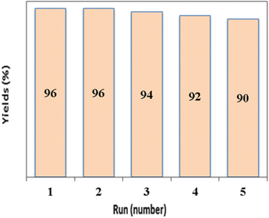
Catalyst reusability is considered one of the key factors from economic, sustainable and practical aspects and is one of the most important principles of green chemistry. In this study, we investigated the reusability of CaMg@MYS using model reactions of benzaldehyde (1 mmol), malononitrile (2 mmol), and cyclohexanone (1 mmol). To discover the efficiency and durability of the alkaline catalyst CaMg@MYS, the reusability of the catalyst was investigated by multicomponent reactions with malononitrile, aromatic aldehydes and cyclohexanone under optimal reaction conditions. Centrifugation was used to extract the catalyst from the reaction mixture after that the reaction was complete. The catalyst was then dried and used in the following step after being rinsed with ethyl acetate. The efficiency and selectivity of tetrahydronaphthalene remained essentially unchanged after five runs, as illustrated in Fig. 8. After being recycled five times, the catalyst shape is unaltered, according to FE-SEM and HR-TEM images as shown in Fig. 9a and b, respectively.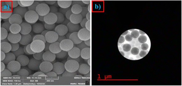 | ||
| Fig. 9 (a) The FE-SEM image after five cycles and (b) the HR-TEM image after five cycles for CaMg@MYS catalyst. | ||
4. Conclusion
In summary, it was demonstrated that silica-on-carbon shells containing calcium and magnesium easily prepared using a modified Stober method and the CaMg@MYS multi-yolk spheres made through two calcination processes in both the argon and air atmospheres. The CaMg@MYS multi-yolk spheres demonstrated both strong catalytic performance and a significant factor as a novelty in multicomponent processes in compared with metal oxide nanostructures. In compared with traditional core–shell structures, the silica shell's prominent cavity makes the surface nanoparticles considerably more accessible, while the silica walls' thinness and high porosity make encapsulation easier. It is anticipated that by adjusting the size, make-up, and morphology of both the inner core and outer shells, the absorption capabilities of these yolk–shell microspheres can be further improved. In multicomponent reactions, the CaMg@MYS catalyst exhibits promising qualities as an effective and reusable catalyst.Conflicts of interest
The authors declare no conflict of interest including any financial, personal or other relationships with other people or organizations.Acknowledgements
The authors are grateful to University of Kashan for supporting this work by Grant No. 159148/95.References
- Z. Wang, S. Akter Monny and L. Wang, ChemNanoMat, 2020, 6, 881–888 CrossRef CAS
.
- D. Zhang, J. Qian, Y. Yi, O. J. Kingsford and G. Zhu, J. Electroanal. Chem., 2019, 847, 113229 CrossRef CAS
.
- Y. Xu, F. Y. H. Kutsanedzie, M. M. Hassan, J. Zhu, H. Li and Q. Chen, Sens. Actuators B Chem., 2020, 324, 128718 CrossRef CAS
.
- S. S. Park and C.-S. Ha, Adv. Funct. Mater., 2018, 28, 1703814 CrossRef
.
- J. Hu, M. Chen, X. Fang and L. Wu, Chem. Soc. Rev., 2011, 40, 5472 RSC
.
- J. Wang, Y. Cui and D. Wang, Adv. Mater., 2019, 31, 1801993 CrossRef PubMed
.
- S. Lu, Y. Sun, Y. Xu, S. Guo, A. Cao and L. Wan, ChemNanoMat, 2020, 6, 1298–1314 CrossRef CAS
.
- J. Wang, M. M. Hassan, W. Ahmad, T. Jiao, Y. Xu, H. Li, Q. Ouyang, Z. Guo and Q. Chen, Sens. Actuators B Chem., 2019, 285, 302–309 CrossRef CAS
.
- J. Wen, H. Guo, X. Ma, Z. Wei, X. He, L. Zhang, B. Li, T. Wang and Y. Cheng, Catal. Sci. Technol., 2020, 10, 3739–3747 RSC
.
- N. Liu, Z. Lu, J. Zhao, M. T. McDowell, H.-W. Lee, W. Zhao and Y. Cui, Nat. Nanotechnol., 2014, 9, 187–192 CrossRef CAS PubMed
.
- J. Qi, X. Lai, J. Wang, H. Tang, H. Ren, Y. Yang, Q. Jin, L. Zhang, R. Yu, G. Ma, Z. Su, H. Zhao and D. Wang, Chem. Soc. Rev., 2015, 44, 6749–6773 RSC
.
- H. Wu and Y. Cui, Nano Today, 2012, 7, 414–429 CrossRef CAS
.
- J. Wang, H. Tang, H. Wang, R. Yu and D. Wang, Mater. Chem. Front., 2017, 1, 414–430 RSC
.
- R. Purbia and S. Paria, Nanoscale, 2015, 7, 19789–19873 RSC
.
- Z. Li, M. Li, Z. Bian, Y. Kathiraser and S. Kawi, Appl. Catal. B, 2016, 188, 324–341 CrossRef CAS
.
- M. Rajabzadeh, R. Khalifeh, H. Eshghi and M. Bakavoli, J. Catal., 2018, 360, 261–269 CrossRef CAS
.
- S. Mohammadi and H. Naeimi, Curr. Org. Synth., 2021, 18, 214–224 CAS
.
- A. Chen, K. Xia, L. Zhang, Y. Yu, Y. Li, H. Sun, Y. Wang, Y. Li and S. Li, Langmuir, 2016, 32, 8934–8941 CrossRef CAS PubMed
.
- M. Zhu, J. Tang, W. Wei and S. Li, Mater. Chem. Front., 2020, 4, 1105–1149 RSC
.
- M. Zhu, Y. Cheng, Q. Luo, M. El-khateeb and Q. Zhang, Mater. Chem. Front., 2021, 5, 2552–2587 RSC
.
- D. Enders, M. R. M. Hüttl, C. Grondal and G. Raabe, Nature, 2006, 441, 861–863 CrossRef CAS PubMed
.
- A. Padwa, Chem. Soc. Rev., 2009, 38, 3072 RSC
.
- T. Mizuno, N. Okamoto, T. Ito and T. Miyata, Tetrahedron Lett., 2000, 41, 1051–1053 CrossRef CAS
.
- T. Mizuno and Y. Ishino, Tetrahedron, 2002, 58, 3155–3158 CrossRef CAS
.
- X.-S. Wang, M.-M. Zhang, Q. Li, C.-S. Yao and S.-J. Tu, Tetrahedron, 2007, 63, 5265–5273 CrossRef CAS
.
- B. Jiang, X. Wang, F. Shi, S.-J. Tu and G. Li, Org. Biomol. Chem., 2011, 9, 4025 RSC
.
- S.-L. Cui, X.-F. Lin and Y.-G. Wang, J. Org. Chem., 2005, 70, 2866–2869 CrossRef CAS PubMed
.
- S. Kazempour and H. Naeimi, New J. Chem., 2023, 47, 412–420 RSC
.
- H. Naeimi, V. Nejadshafiee and M. R. Islami, Microporous Mesoporous Mater., 2016, 227, 23–30 CrossRef CAS
.
- Z. Rashid, H. Naeimi, A.-H. Zarnani, M. Nazari, M.-R. Nejadmoghaddam and R. Ghahremanzadeh, RSC Adv., 2016, 6, 36840–36848 RSC
.
- M. Taheri, H. Naeimi and A. H. Ghasemi, RSC Adv., 2023, 13, 3623–3634 RSC
.
- B. Maleki, R. Rooky, E. Rezaei-seresht and R. Tayebee, Org. Prep. Proced. Int., 2017, 49, 557–567 CrossRef CAS
.
- Y. Wan, X. Zhang, L. Zhao, C. Wang, L. Chen, G. Liu, S. Huang, S. Yue and W. Zhang, J. Heterocycl. Chem., 2014, 50, 814–820 Search PubMed
.
- T. Lohar, A. Kumbhar, M. Barge and R. Salunkhe, J. Mol. Liq., 2016, 224, 1102–1108 CrossRef CAS
.
- N. Azizi, T. S. Ahooie and M. M. Hashemi, J. Mol. Liq., 2017, 246, 221–224 CrossRef CAS
.
- M. Dashteh, M. A. Zolfigol, A. Khazaei, S. Baghery, M. Yarie, S. Makhdoomi and M. Safaiee, RSC Adv., 2020, 10, 27824–27834 RSC
.
- X. Sun and Y. Li, Angew. Chem., Int. Ed., 2004, 43, 3827–3831 CrossRef CAS PubMed
.
- H. Naeimi and S. Mohammadi, ChemistrySelect, 2020, 5, 2627–2633 CrossRef CAS
.
- M. Khorasani and H. Naeimi, Synth. Commun., 2022, 52, 1917–1925 CrossRef CAS
.
- H. Naeimi and S. Mohammadi, J. Heterocycl. Chem., 2020, 57, 50–59 CrossRef CAS
.
- Y. A. Sharanin, Y. A. Baskakov, Y. T. Abramenko, Y. G. Putsykin, A. F. Vasil'ev and E. B. Nazarova, J. Org. Chem., 1980, 16, 1870–1879 Search PubMed
.
- W. Li, F. Wang, Y. Shi and L. Yu, Chin. Chem. Lett., 2023, 34, 107505 CrossRef CAS
.
Footnote |
| † Electronic supplementary information (ESI) available. See DOI: https://doi.org/10.1039/d3ra02740f |
| This journal is © The Royal Society of Chemistry 2023 |

