DOI:
10.1039/D3RA02659K
(Paper)
RSC Adv., 2023,
13, 13423-13437
Synthesis, photoluminescence, Judd–Ofelt analysis, and thermal stability studies of Dy3+-doped BaLa2ZnO5 phosphors for solid-state lighting applications
Received
21st April 2023
, Accepted 26th April 2023
First published on 3rd May 2023
Abstract
Here, we report a series of white-emitting Ba(La2−xDyx)ZnO5 (x = 0–7 mol%) phosphors synthesized via a high-temperature solid-state reaction. The synthesized phosphor's phase purity and tetragonal crystal structure were confirmed by an X-ray powder diffraction (XRPD) pattern. The wide bandgap characteristic feature was assessed through reflectance spectra, and the estimated bandgap was found to be 4.70 eV. Besides analyzing the effect of doping on the surface morphology, the distribution of ions on the surface was observed through the secondary ion mass spectroscopy technique. The synthesized phosphor was found to display bluish (486 nm) and yellowish (576 nm) bands in the emission spectra under the excitation of 325 nm and 352 nm, which together are responsible for producing the white luminescence. The analysis of Judd–Ofelt parameters indicates the symmetric nature of Dy3+ substitution in the present host. The thermal stability of the phosphor was assessed by varying the temperature up to 403 K, and it was found that the synthesized phosphor possesses improved thermal stability with an activation energy of 0.29 eV. The photometric evaluations of the present phosphor revealed the CIE coordinates around the near-white regime (0.3448, 0.3836), along with the color-correlated temperature value of 5102 K. All research on this luminescent material's unique features points to the possibility of using it to fabricate white-light-emitting devices for solid-state lighting applications.
Introduction
The digital world of today is experiencing a considerable energy shortage due to the development of technology and the inefficient use of the world's energy resources, particularly for lighting.1 If available energy is not used cautiously and properly, catastrophic scenarios will occur sooner rather than later. Thus, it is crucial to encourage and simultaneously look for effective energy-saving measures to avoid these disastrous scenarios.2 After considering the causes, it appears that the key factor is the inefficiency displayed by machinery that consume a huge amount of energy but generate very little in return. The key to lowering energy usage in this area is carefully selecting high-efficiency phosphors because light is crucial to our everyday lives in the twenty-first century.3 Phosphors are light-emitting materials composed of a host matrix and an activator.4 These materials possess the capability to transform light from its higher frequency domain to a lower frequency domain via different electronic transitions.5 Phosphor materials are regarded as an affordable energy source that can satisfy present and future energy demands on a worldwide basis. According to a recent report by the US Department of Energy, LEDs are expected to reduce lighting energy consumption by 15% in 2020 and by 40% in 2030, saving 3.0 quads in 2030 alone, which would amount to over $26 billion in savings at the current price of energy.6,7 Additionally, these energy savings would result in a 180 million metric ton reduction in greenhouse gas emissions. During the next ten years, the DOE predicts that the traditional methods of illuminating our planet, which began with incandescent light bulbs and progressed to overhead fluorescent ones, may become outdated.8
Several fields of science and technology have undergone a tremendous transformation because of phosphor-based lighting technology.9 For application in solid-state lighting systems, researchers are continuously studying various phosphor materials that are reliable, inexpensive, eco-friendly, have a longer lifespan, etc.10,11 At the moment, multidisciplinary efforts are being made with an emphasis on creating phosphor materials with improved luminous properties.2 In several inorganic host matrices, rare-earth (RE) ions are known to be effective initiators for luminous centers. They are extremely effective in increasing the quantum efficiency of phosphors because of their special electronic structures, which consist of partially filled 4f shells surrounded by 5s2 and 5p6 electrons.12,13 Controlling the optical and photoluminescence (PL) properties of various host matrixes is possible by using the RE ions as an dopants.13 Nonetheless, the research community has focused on creating white-light-emitting diodes (wLEDs) with efficient characteristic parameters and efficiency since they may be used effectively for lighting and many display applications.14 At the beginning of phosphor technology, wLEDs were developed by combining UV/blue LEDs with appropriate phosphor material. However, these wLEDs were found to have inappropriate CRI and CCT values due to a lack of red components in the emission spectra.15,16 Later on, wLEDs were developed by coating the near-UV LED chips with tricolor (red, green, and blue) phosphor materials. But it was found that wLEDs developed via this process possess a very short lifetime and lack the features of eco-friendliness due to the presence of a poor red component.3 Continuing with the aim of fabricating efficient wLEDs, researchers have developed an interest in fabricating single-composition wLED phosphor materials.1,17 In this regard, trivalent dysprosium (Dy3+) is thought to be an efficient activator for the fabrication of wLEDs due to its strong white emission. Dy3+-ion possesses a complex intra-4f electronic configurational band that allows a wide range of electronic transitions, thereby exhibiting better white emission spectra composed of yellow (Y) and bluish (B) bands when excited by near UV wavelengths. Thus, the optimization of the bands (Y and B) results in the generation of effective white light.18,19
For the generation of white light, different varieties of host matrices have been explored, such as phosphates, oxides, sulfates, aluminates, vanadates, etc.20–26 Amongst all the mentioned host matrices, oxide hosts are considered to be the most important because of their characteristic features like stable crystal structure, ease of synthesis, economical, increased tensile strength, high chemical and thermal stability, moisture resistance, and most importantly, their eco-friendly nature.20,27,28 Furthermore, the oxide host materials were found to have a broad bandgap and inefficient luminous characteristics. Among the different oxide hosts, BaLa2ZnO5 is considered an efficient luminous host due to its stable crystal structure and thermal stability.29 The structural framework of this host is comprised of ten- and eight-fold polyhedra of BaO10 and LaO8, with C2v and D4 symmetry, respectively, and four-fold coordinate sites occupied by Zn2+.30 In light of the above discussion, BaLa2ZnO5 was selected for the presented study as it is an enigmatic host for different structural and optical studies.
There have been several past articles on this host, such as Song et al.,31 studied the thermometric properties of Bi3+/Sm3+-doped BaLa2ZnO5. Using the combustion approach, Sehrawat et al.30,32 investigated the green and white light emissions caused by the emissions of Er3+ and Dy3+ doping in the host. The sol–gel approach was used by Singh et al.33,34 for studying the luminescence properties of Sm3+ and Tb3+ doping in BaLa2ZnO5. Using the combustion approach, Dahiya et al.,35 have also studied the luminescence properties of Tb3+-doped BaLa2ZnO5. Similarly, Xie et al.36 have performed the synthesis and up-conversion luminescence properties of Ho3+, Yb3+ co-doped BaLa2ZnO5 and observed that synthesized phosphors possess strong green and weak red up-conversion emissions centered at 548 nm, 664 nm, and 758 nm. Similarly, comparable studies of the structural and luminescent characteristics of Nd3+, Tb3+, and Eu3+ have also been done in other works.
From the above discussion, it is clear that several authors reported the synthesis of RE3+-doped BaLa2ZnO5 phosphors by using combustion or sol–gel methods. It has also been found that in all the investigations, the luminescence studies have been carried out in either one of the three spectral regions—ultraviolet, visible, or near-infrared. Furthermore, none of the investigations have studied the distribution of ions using time-of-flight secondary ion mass spectrometry (ToF-SIMS) and the thermal behavior of the synthesized phosphor materials. In this work, an effort has been made to prepare Dy3+-doped BaLa2ZnO5 phosphors by using a solid-state reaction method. The main aim was to determine its crystal structure and study the effect of different Dy3+ ion concentrations on the optical and luminescent properties of prepared phosphor materials. Comprehensive luminescence studies were carried out by recording the emission spectra in the ultraviolet, visible, and NIR regions. Additionally, the surface morphology, elemental composition, and ion distribution were also studied. The behavior of doping on the host was analyzed through the calculation of Judd–Ofelt intensity parameters. The thermal stability of the synthesized phosphor was analyzed through temperature-dependent luminescence spectra. The lifetime of the synthesized phosphor was computed from the decay profile. The detailed study has revealed that the synthesized Ba(La2−xDyx)ZnO5 (x = 0–7 mol%) phosphor can act as an efficient candidate for fabricating wLED for solid-state lighting applications.
Materials synthesis and characterization
A series of Ba(La2−xDyx)ZnO5 (x = 0–7 mol%) phosphor material was synthesized by using the solid-state reaction method. All the precursors employed, i.e., BaCO3 (99.9%), La2O3 (99.9%), ZnO (99.9%), and Dy2O3 (99.9%), were procured from Sigma Aldrich. Following the stoichiometric calculations, the required amount of all the precursors was thoroughly mixed in an agate mortar for several hours. During mixing, ethyl alcohol was added at regular intervals for proper homogenization. The mixture was then transferred to an alumina crucible and kept in a muffle furnace at 900 °C for 2 h with a heating and cooling rate of 5° min−1. The mixture was removed from the furnace for further grinding and then calcinated at 1200 °C for 6 h with a heating and cooling rate of 5° min−1. After calcination, the mixture was ground into a powder form of the desired nanomaterial.
The phase purity of the synthesized phosphor samples was confirmed using a Bruker AXS D8 Advanced X-ray Diffractometer (Cu-Kα) functioning at high resolution with a specific voltage and tube current of 40 kV and 40 mA, respectively. Band-gap analysis was performed by recording the diffuse reflectance spectra using a PerkinElmer Lambda 950 spectrometer. Morphological and compositional measurements were performed using a JEOL JSM-7800F scanning electron microscope (SEM), equipped with an energy-dispersive X-ray spectroscopy (EDS) system. Time-of-flight secondary ion mass spectroscopy (ToF-SIMS 5) was employed for recording the surface maps displaying the distribution of ions. Photoluminescence spectra of synthesized phosphor material were recorded by using a Varian Carry-Eclipse fluorescence spectrophotometer coupled with a xenon lamp and photomultiplier tube (PMT) for excitation and recording PL spectra. Also, the He–Cd laser system with a 325 nm excitation wavelength was employed for recording the PL spectra in both the visible and NIR regions, along with temperature-dependent PL. Phosphorescence lifetime measurements were carried out using the FS5 fluorescence spectrophotometer.
Results and discussion
Phase purity and crystal structure
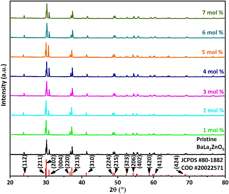
Fig. 1 represents the XRPD pattern of the synthesized series of Ba(La2−xDyx)ZnO5 (x = 0–7 mol%) phosphor. The obtained XRPD pattern was found to be consistent with the joint committee on powder diffraction standard (JCPDS) 01-080-1882 along with the crystallographic open database (COD) #2002571, thereby confirming the phase of synthesized phosphor material. From the JCPDS data file, it was found that the synthesized phosphor possesses a tetragonal phase structure with space group I4/mcm (140) and lattice parameters a = b = 6.9091 Å and c = 11.5907 Å.
 |
| | Fig. 1 X-ray powder diffraction pattern of Ba(La2−xDyx)ZnO5 (0–7 mol%) phosphor materials along with the standard diffraction pattern peaks pattern. | |
The absence of impurity peaks in the XRPD pattern at different doping concentrations established the fact that Dy3+ doping has not altered the basic crystal structure of BaLa2ZnO5. According to Vegard's mixing rule, dopant Dy3+ ions are supposed to replace La3+ ions in the host matrix. The replacement of the host lattice ion (La3+) by the dopant lattice ions (Dy3+) was validated by calculating the percentage radius difference (Δr) using the following formula:37
| |
 | (1) |
In the above equation,
Rm,
Rd, and CN stand for effective ionic radii for host and dopant lattice ions along with their respective coordination numbers. By substituting the respective values in the above equation, the value of Δ
r was estimated to be 11.62, which is quite less than the acceptable limit of 30 percent.
38 The calculated value of Δ
r completely suggests the replacement of La
3+ ions by Dy
3+ ions, which is also evident by observing a slight shift in the XRPD pattern towards the right. Furthermore, other options for the replacement of Ba
2+ and Zn
2+ ions by the dopant Dy
3+ ions are ruled out due to dissimilarity in their ionic radii and charges, which results in considerable percentage radii differences.
32
In addition, the average crystallite size (D) of the synthesized phosphor was estimated by using the fundamental Scherrer's equation:39
| |
 | (2) |
In the above equation,
D represents the grain size,
λ represents the wavelength of the employed X-ray source (Cu-K
α radiation,
λ = 0.154 nm), and
β represents the value of the full-width half maxima (FWHM) of prominent peaks residing at angle
θ. Applying the empirical formula, the average crystallite size was estimated to be 81.70 nm.
Band-gap analysis
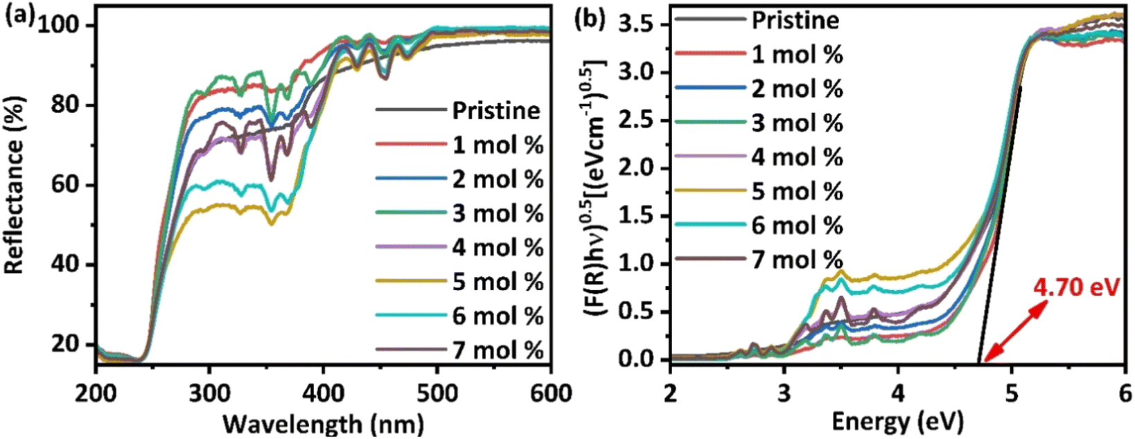
For examining the effect of Dy3+-doping on the optical properties of BaLa2ZnO5, diffuse reflectance spectra (DRS), depicted in Fig. 2(a), were recorded from 200 to 800 nm using a UV-visible spectrophotometer. From the figure, it is evident that at the initial concentrations of doping, the reflectance percentage slightly increases; however, as the concentration increases, a further decrease in the reflectance percentage from 80% to 60% is evident from the plot. A decrease in the reflectance percentage, in turn, tends to enhance the emission properties of the host. In addition, feeble peaks are evident in the reflectance plot for doped samples in the range of 290 nm to 480 nm, which has been ascribed to the intraconfigurational 4f transitions of Dy3+-ions. Among the different peaks, two prominent peaks at 367.46 nm and 453.96 nm correspond to the 6H15/2 → 6P3/2,5/2 transitions of Dy3+-ions, respectively.32 The existence of weak peaks in the reflectance spectra highlights the practical application of the synthesized phosphor material for wLEDs.
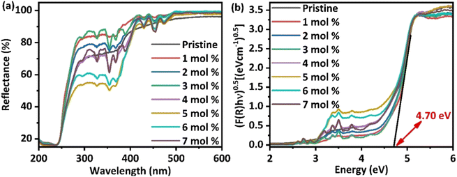 |
| | Fig. 2 (a) Diffusive reflectance spectra for Ba(La2−xDyx)ZnO5 (x = 0–7 mol%) phosphor (b) Tauc's plot for estimating the indirect bandgap of synthesized phosphor materials. | |
Furthermore, for estimation of the bandgap, the obtained DRS spectra were subjected to a well-known theoretical approach called the Kubelka–Munk function. Correlating the Kubelka–Munk function and Tauc's generalization results in the general eqn (3) that helps in determining the nature of transitions.
| | |
[F(R∞)hν]2 = C(hv − Eg)n
| (3) |
In the above equation,
C is constant,
F(
R∞) represents the Kubelka–Munk function,
hν corresponds to the value of phonon energy, and
n represents the type of electronic transition and can take values of either 1, 3 for direct allowed and forbidden transitions or 4, 6 for indirect allowed and forbidden transitions, respectively. It was observed that synthesized phosphor materials favor the occurrence of indirect allowed transitions.
Fig. 2(b) represents Tauc's plot, from which it is evident that doping does not have to cause any significant change in the bandgap of the materials. The synthesized phosphor was found to have an indirect bandgap of the order of 4.70 eV, indicating that it belongs to the wide bandgap semiconductors and can be effectively used for different photonic, lasing, and optoelectronic applications.
40
Surface morphology and compositional probe
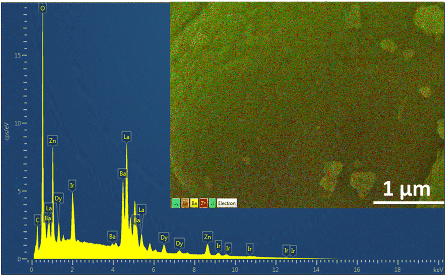
The progression in the microstructures of the Ba(La2−xDyx)ZnO5 phosphor material is depicted in Fig. 3. The different micrographs present in Fig. 3(a)–(d) correspond to the 0 mol%, 1 mol%, 5 mol%, and 7 mol% concentrations of the Dy3+ ion in the host. From the SEM micrographs, it is evident that surface morphology is strongly dependent on the activator concentration of Dy3+. For the pristine sample, the SEM micrographs show uneven particle sizes and irregular shapes. However, at the initial doping concentrations, particles are completely agglomerating together, forming a sheet-like structure. As the doping concentrations increase, further particles start dispersing again in an irregular fashion. However, no such change in the structure is evident due to doping concentration. Also, to confirm the elemental composition, the EDS spectrum was recorded for the optimum doping concentration and is given in Fig. 4. The EDS spectrum validates the compositions, as the emission peaks present in the spectrum correlate with the Ba, La, Zn, O, and Dy.
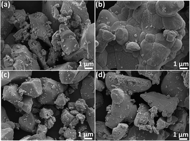 |
| | Fig. 3 SEM images for (a) 0 mol% of Dy3+ (b) 1 mol% of Dy3+ (c) 5 mol% of Dy3+ (d) 7 mol% of Dy3+ in BaLa2ZnO5 phosphor material. | |
 |
| | Fig. 4 EDS spectrum for 5 mol% doped BaLa2ZnO5 coated with Iridium. | |
TOF-SIMS analysis
ToF-SIMS images acquired for the pristine and doped samples (1, 5, and 7 mol%) are presented in Fig. 5(a)–(d). The images were recorded in a zone of 100 × 100 μm2 and then combined overlays were created. These images reveal the topography of the synthesized powder. All the images depicted were recorded after the sputter-cleaning process. The overlay mapping images depict the regular distribution of different ions on the surface. Besides visualizing the distribution of the host ions, i.e., Ba, La, Zn, and O, it is evident that Dy3+-ions have been successfully incorporated into the host lattice. As can be seen from the figures, all the ions present in the host are dispersed consistently in each sample. In addition, the dopant Dy3+ ions also seem to be present throughout the sample's surface.8
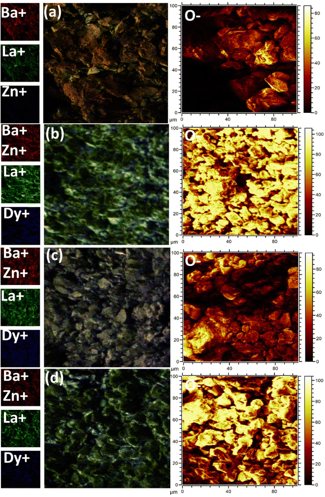 |
| | Fig. 5 TOF-SIMS surface mapping for (a) undoped (b) 1 mol%, concentrations (c) 5 mol% , and (d) 7 mol% concentations of Dy3+ in Ba(La2−xDyx)ZnO5 phosphor. | |
Photoluminescence study
Photoluminescence excitation (PLE) and emission (PL) spectra recorded from 200 nm to 800 nm of the synthesized Ba(La2−xDyx)ZnO5 (x = 1–7 mol%) phosphor materials are depicted in Fig. 6. In the recorded spectra (PLE and PL), there are many peaks because of the intraconfigurational f–f transitions of the Dy3+ ion. The PLE spectra (Fig. 6(a) and (b)) were recorded at an emission wavelength of 577 nm, and the emission was found to consist of a broad charge transfer band (CTB), followed by several peaks at 294.44, 326.67, 352.87, 367.98, 388.37, 429.13, 453.89, and 472.77 nm, which correspond to 6H15/2 → 4K13/2, 6H15/2 → 6P3/2, 6H15/2 → 6P7/2, 6H15/2 → 6P5/2, 6H15/2 → 4I13/2, 6H15/2 → 4G11/2, 6H15/2 → 4I15/2, and 6H15/2 → 4F9/2, respectively.
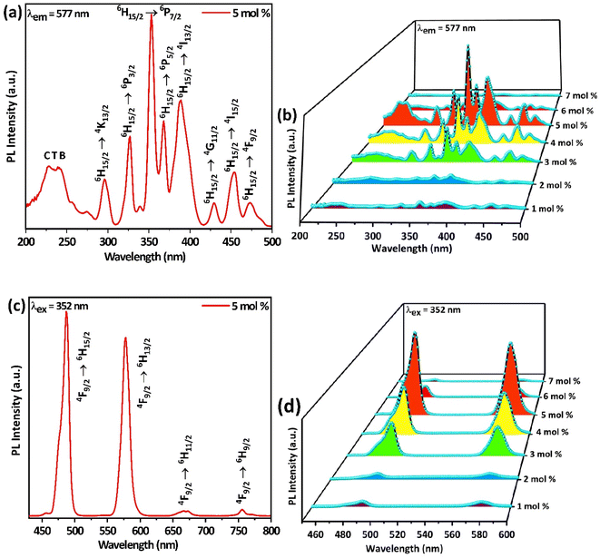 |
| | Fig. 6 (a and b) Excitation spectra of Ba(La2−xDyx)ZnO5 (x = 5 mol%) and 3D-excitation plot for Ba(La2−xDyx)ZnO5 (x = 1–7 mol%), recorded at an emission wavelength of 577 nm. (c and d) Emission spectra of Ba(La2−xDyx)ZnO5 (x = 5 mol%) and 3D-emission plot for Ba(La2−xDyx)ZnO5 (x = 1–7 mol%), recorded at an excitation wavelength of 352 nm. | |
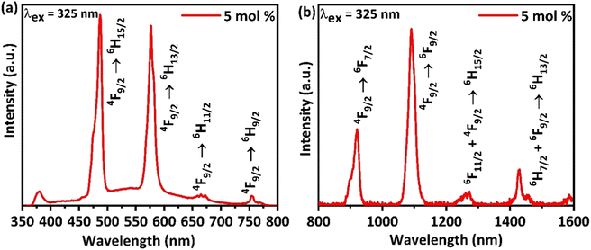
Similarly, while observing the PL spectrum (Fig. 6(c) and (d)) recorded at an excitation wavelength of 352 nm, it consists of two sharp emission peaks at 486.52 (blue) and 576.95 (yellow), which correspond to 4F9/2 → 6HJ (J = 15/2, 13/2), respectively.41,42 In addition, there exist two feeble peaks in the PL spectra at 669.49 and 755.62 nm, which correspond to 4F9/2 → 6H11/2. For analyzing the emission in the NIR, the emission spectrum for the optimum doping concentration was recorded from 300 to 1600 nm by using a UV excitation 325 nm PL laser system, which is depicted in Fig. 7.
 |
| | Fig. 7 (a) Emission spectra of Ba(La2−xDyx)ZnO5 (x = 5 mol%) from UV to visible and (b) visible to NIR regions of the electromagnetic spectrum recorded by using an excitation wavelength of 325 nm. | |
The emission spectra recorded by the PL laser system (Fig. 7(a)) are similar to those presented in Fig. 6(c) and (d), thereby further illustrating the observed spectra. However, the emission spectrum of the synthesized phosphor in the NIR region (Fig. 7(b)) possesses two sharp peaks at 920 nm and 1090 nm and two feeble peaks around 1260 nm and 1426 nm. These two sharp peaks correspond to the transitions from 4F9/2 → 6FJ (J = 7/2, 9/2), respectively.43
The most peculiar thing to observe in the emission spectrum of synthesized phosphor is that all the emissions mostly arise from the 4F9/2 energy level to different ground state levels. The different transitions involved in the emission from UV to NIR regions are well depicted in the energy level diagram shown in Fig. 8. During the early phase of excitation, the electrons residing in the ground state get stimulated into different excited states. From the different excitations these electrons reach the stable quantum mechanical state 4F9/2 via non-radiative transitions. Finally, the blue and yellow emission transitions occur from the stable 4F9/2 state to different ground-state energy levels.
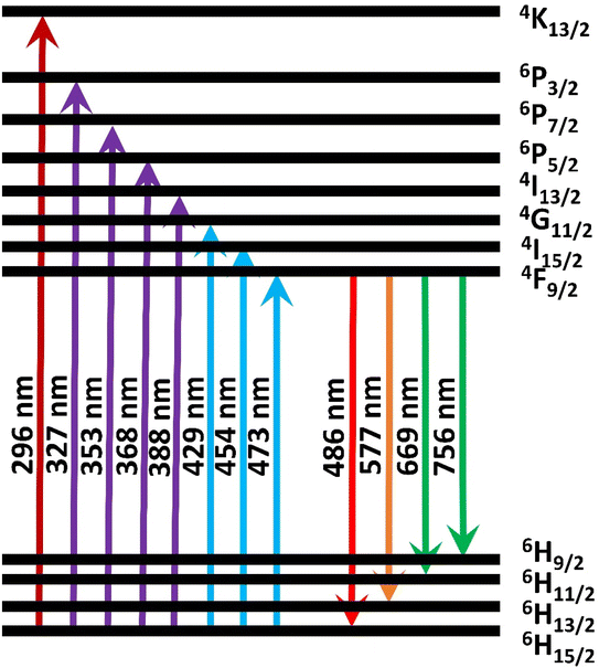 |
| | Fig. 8 Energy level diagram corresponding to the excitation and emission spectra of Dy3+ activated BaLa2ZnO5. | |
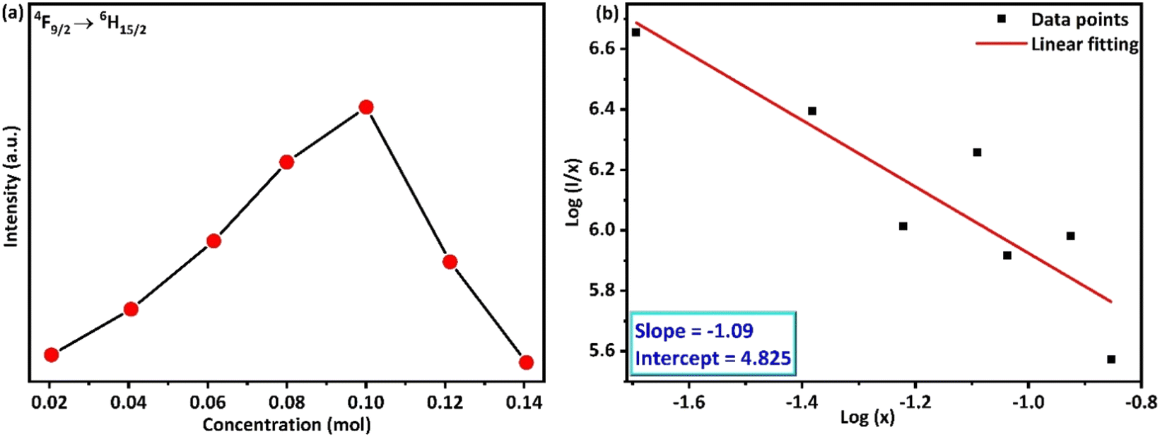
The impact of doping on the host materials is evident from the varying PLE and PL intensities (Fig. 6(c) and (d) and 9(a)). Although all the profiles are similar, a gradual increase in intensity is observed until the amount of doping acquires a 5 mol% value, after which a significant drop in intensity is observed. The decrease in intensity is caused by the concentration quenching (CQ) phenomenon, which may be the result of non-radiative (nR) cross-relaxation processes. The validation of the nR cross-relaxation process can be done by calculating the value of the critical distance (Rc) using Blasse's equation:44
| |
 | (4) |
In the above equation,
V stands for the volume of the unit cell,
X represents the value of the optimal doping concentration, and
N stands for the number of replaceable cations. By substituting the respective values in the above equation, we get a value of
Rc = 13.82 Å, which is quite larger than the acceptable value of 5 Å, thereby ruling out the possibility of CQ through nR cross-relaxation pathways.
45 Therefore, the phenomenon of CQ can either be due to radiative reabsorption or multipolar interaction phenomena. However, there is no evidence of overlap between the excitation and emission, which thereby clearly infers the non-occurrence of radiative reabsorption processes.
32 Thus, the effective pathway for CQ is due to multipolar interactions, which can be assessed by using Dexter's generalization.
46,47 The amount of energy being transferred is governed by the extent of interaction between the luminescence centers. While studying the CQ phenomenon, Huang
et al.,
48 found that the interaction between the luminescence centers has a strong correlation with the luminescence intensity and doping concentration. The relation between them can be well understood from Huang's equation:
48| |
 | (5) |
| |
 | (6) |
In the above
eqn (5) and
(6),
I stand for peak intensity corresponding to the optimal doping concentration value
x, and
s represents the type of interaction, which can be either dipole–dipole (
s = 6), dipole–quadruple (
s = 8), or quadruple–quadruple (
s = 10).
Γ corresponds to the probability of the occurrence of donor intrinsic transitions. Inference about the type of interaction can be estimated by solving the above
eqn (5) and
(6), which result in the following general equation:
49| |
 | (7) |
In the above equation,
f is a constant, and
I represent the intensity corresponding to the different concentrations of doping (Dy
3+). The term “−
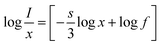
s/3” in the above equation represents the slope of the graph plotted in between log(
I/
x)
vs. log(
x) and was estimated to be −1.09 (
Fig. 9(b)). Therefore, the measured value of
s was found to be 3.27, which suggests the only option for the energy transfer and subsequent CQ phenomenon is the occurrence of some exchange-type interaction within the synthesized phosphor.
32 As the concentration of Dy
3+ ions exceeds its optimum values, the space between the activator ions starts decreasing, which results in the initiation of some non-radiative exchange-type of interactions. As a result, a decrease in emission intensity is observed. All the above-discussed photoluminescence results are also endorsed by the DRS spectra results discussed above.
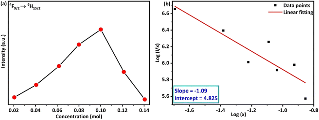 |
| | Fig. 9 (a) Variation of emission intensity (4F9/2 → 6H15/2) with variation in the doping concentration (b) logarithmic variation of the PL intensity of Dy3+ doped BaLa2ZnO5 phosphor. | |
Judd–Ofelt analysis
For understanding the variation in the intensities of the blue and yellow bands, optimization of radiative transfer was done by employing the Judd–Ofelt (JO) theory.50,51 The line strength of the activator ions was computed from the excitation spectra using the magnetic dipole (MD) and electric dipole (ED) transitions. The probability of occurrence for ED transitions is higher than that of MD transitions.52 Luo et al.53 have envisaged a simplistic approach for determining the JO parameters for powder samples based on their excitation spectra. The same approach was put to use on many systems, and it was found that the computed results are in good agreement with the results obtained via the conventional method. Dutta et al.52 have also reported a comprehensive formalism for the estimation of the JO parameters using the excitation spectra. In the current study, a similar formalization was opted for when computing the line strength:| |
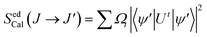 | (8) |
Here, |U′| represents the unit tensor operator, Ω2, Ω4, and Ω6 denote the JO intensity parameters. These parameters provide information about the impact of the host on the plausibility of the transition. Furthermore, employing the excitation spectra, experimental line strengths were also calculated using the following eqn (9):| |
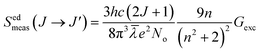 | (9) |
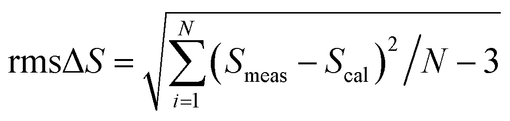
J and J′ represent the angular momentum quantum numbers corresponding to the ground and excited states. n is the value of the refractive index of the sample, and Gexc is computed from the integral excitation intensity. Thereafter, for computing the JO parameters, the least squares fitting method was employed between the calculated and experimental line strengths. The deviation among them was calculated using the root mean square (rms) parameters| |
 | (10) |
where N corresponds to the band number. The computed JO parameters for different concentrations of Ba(La2−xDyx)ZnO5 (x = 1–7 mol%) were plotted as shown in Fig. 10. According to the existing literature, the Ω2 value of 5 mol% Dy3+-doped BaLa2ZnO5 phosphor was found to be comparatively low, i.e., 0.82 × 10⁻²⁴ cm2.52 The low value of Ω2 pointed to the high symmetry of the ligand environment surrounding Dy3+ ions. When the concentration of Dy3+ increased, it was found that the Ω2 value of the Dy3+-doped BaLa2ZnO5 phosphor changed slightly, modifying its covalent nature due to the overlap of molecular orbitals between O2− ion (p-orbital) and Dy3+ (f-orbital). The electron cloud extended as a result of the orbital overlap, creating a connection with a stronger covalent character. According to the JO analysis, Dy3+ ion placement follows inversion symmetry. The variation of Ω4 parameters with Dy3+ concentration was observed to be almost negligible, indicating the strong symmetric nature of Dy3+ ions in the present host. Owing to this excellently symmetric nature, blue and yellow emissions can provide near-white emissions from the present phosphor materials.
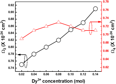 |
| | Fig. 10 Variation of Ω2 and Ω4 for Ba(La2−xDyx)ZnO5 (x = 1–7 mol%) host matrix. | |
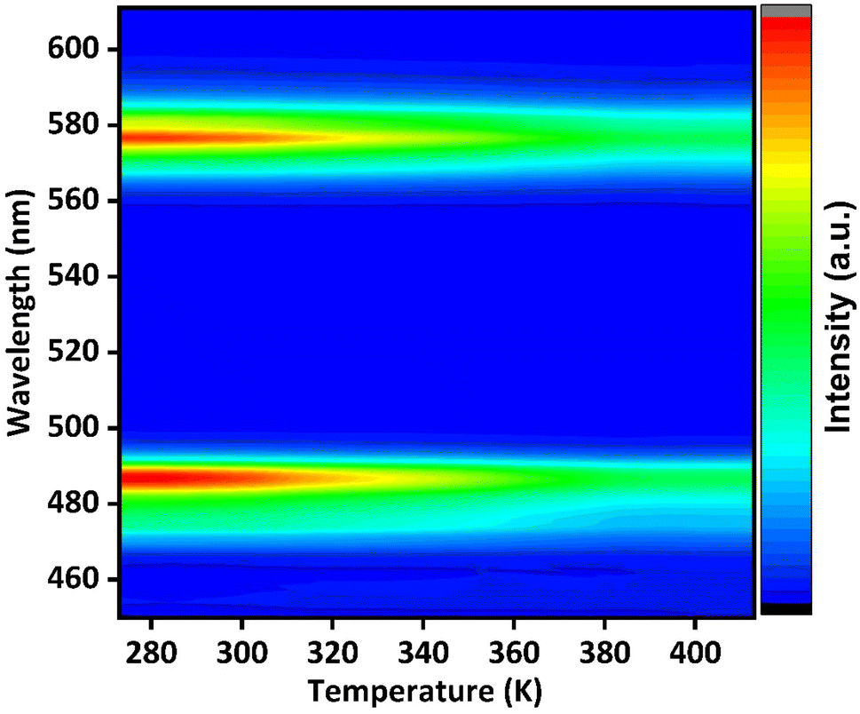
Thermal stability
The thermal stability parameter is another prominent factor in determining the effectiveness of phosphor materials. In this regard, temperature-dependent PL emission of Ba(La2−xDyx)ZnO5 (x = 5 mol%) was recorded by using Kimmon IK Series 325 nm Laser Source excitation from room temperature to 410 K, and the variation in intensity observed is depicted in Fig. 11.
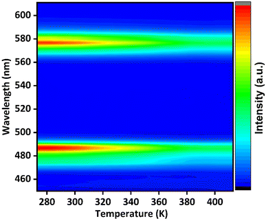 |
| | Fig. 11 Temperature-dependent photoluminescence spectra of Ba(La2−xDyx)ZnO5 (x = 5 mol%) phosphor. | |
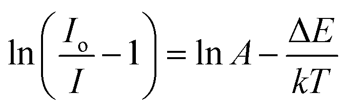
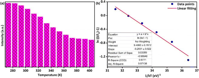
It is evident from Fig. 11 that the position of emission bands did not change as the temperature increased from room temperature to 410 K. This invariability of the emission peak position helps in recording the steady-state emission even at elevated temperatures. However, an increase in temperature tends to decrease the intensity of PL emission, as is evident from Fig. 11 and 12(a), due to different temperature quenching processes.54 Fig. 12(a) represents the variation of intensity with the rise in temperature. The total variation in intensity can be divided into three temperature regions: 273–313 K, 323–373 K, and 383–403 K, respectively. As the temperature increases from room temperature, a slight variation in intensity is observed, suggesting a stable thermal behavior up to 313 K. However, in the second region (323–373 K), a gradual decrease in intensity is observed, which again stabilizes after 383 K. Beyond that, the PL intensity shows stabilized behavior up to 403 K, which confirms the good thermal stability of the synthesized phosphor. The essence of thermal quenching, due to which the gradual decrease in intensity occurs from 323 to 373 K, can be observed by determining the activation energy using the following equation:55
| |
 | (11) |
In the above equation,
Io represents the intensity at room temperature,
I denotes the emission intensity at different temperatures (
T),
A is constant, Δ
E signifies activation energy, and
k stands for the Boltzmann constant.
Fig. 12(b) represents the curve corresponding to ln(
Io/
I − 1)
versus 1/
kT for Ba(La
2−xDy
x)ZnO
5 (
x = 5 mol%) phosphor. The slope for the plot was estimated through linear fitting and is around −0.29, revealing that the value of activation energy is 0.29 eV for synthesized Ba(La
2−xDy
x)ZnO
5 (
x = 5 mol%) phosphors. Obtained activation energy endorses excellent thermal stability and its applicability in high-power wLEDs and other applications.
54
 |
| | Fig. 12 (a) Bar chart plot depicting the variation of emission intensity with an increase in temperatures (b) Arrhenius plot for estimation of the activation energy of synthesized Ba(La2−xDyx)ZnO5 (x = 5 mol%) phosphor. | |
Lifetime and photometric analysis
The phenomenon of energy transfer can be further evaluated by analyzing the decay curves. The decay curves depicted in Fig. 13(a) were recorded using an excitation and emission wavelength of 352 nm and 577 nm, respectively. It was observed that all the curves were not following the single exponential trend, which can be attributed to the unequal distribution of dopant ions in the host matrix.19 Thus, the decay curves were fitted by the double exponential function:56| |
I(t) = Io + A1![[thin space (1/6-em)]](https://www.rsc.org/images/entities/char_2009.gif) exp−t/τ1 + A2exp−t/τ2 exp−t/τ1 + A2exp−t/τ2
| (12) |
In the above eqn (12), I(t) represents emission intensity at some time (t), Io represents the background intensity, A1 and A2 are constants, and τ1 and τ2 correspond to lifetimes for different decays, respectively. The average lifetime was calculated using the following equation:| |
 | (13) |
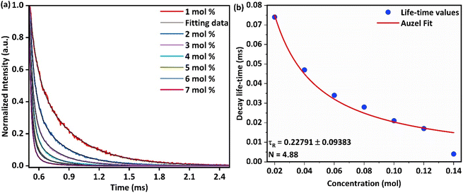 |
| | Fig. 13 Luminescence decay curves of synthesized Ba(La2−xDyx)ZnO5 phosphor (x = 1–7 mol%) (b) Auzel's fitting for calculation of the intrinsic radiative lifetime of the synthesized phosphor material. | |
Employing the above eqn (13), it was observed that the average lifetime of the synthesized phosphor decreases from 0.074 ms to 0.004 ms (Table 1) as the concentration of Dy3+ varies from 1 to 7 mol% due to the nR energy relocation phenomenon.
Table 1 Fitting parameters and the calculated average lifetime values for varying doping concentrations of Dy3+ in synthesized Ba(La2−xDyx)ZnO5 phosphor materials
| Concentration (mol%) |
Adj R2 value |
Chi-square value (× 10−6) |
Average lifetime (ms) |
| 1 |
0.9994 |
6.00 |
0.074 |
| 2 |
0.9994 |
3.39 |
0.047 |
| 3 |
0.9993 |
2.05 |
0.034 |
| 4 |
0.9995 |
1.17 |
0.028 |
| 5 |
0.9056 |
175 |
0.021 |
| 6 |
0.9998 |
0.27 |
0.017 |
| 7 |
0.9999 |
0.12 |
0.004 |
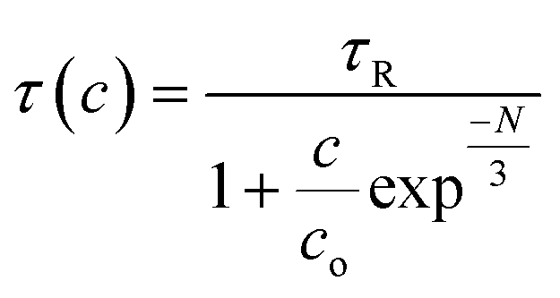
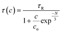
The observed decrease in a lifetime with the increase in the concentration of Dy3+ was further assessed through Auzel's model (Fig. 13(b)) by using the following equation:
| |
 | (14) |
Here,
c represents the variable concentration of the dopant ions in terms of mol%,
τ(
R) represents the intrinsic lifetime, and
N represents the total number of photons generated during the relaxation of the
4F
9/2 state to different ground states
via nR processes. Furthermore,
4F
9/2 is the only stable quantum mechanical state in Dy
3+ and is responsible for other radiative relaxations with a radiative lifetime
τ(
R) of 0.23 ms.
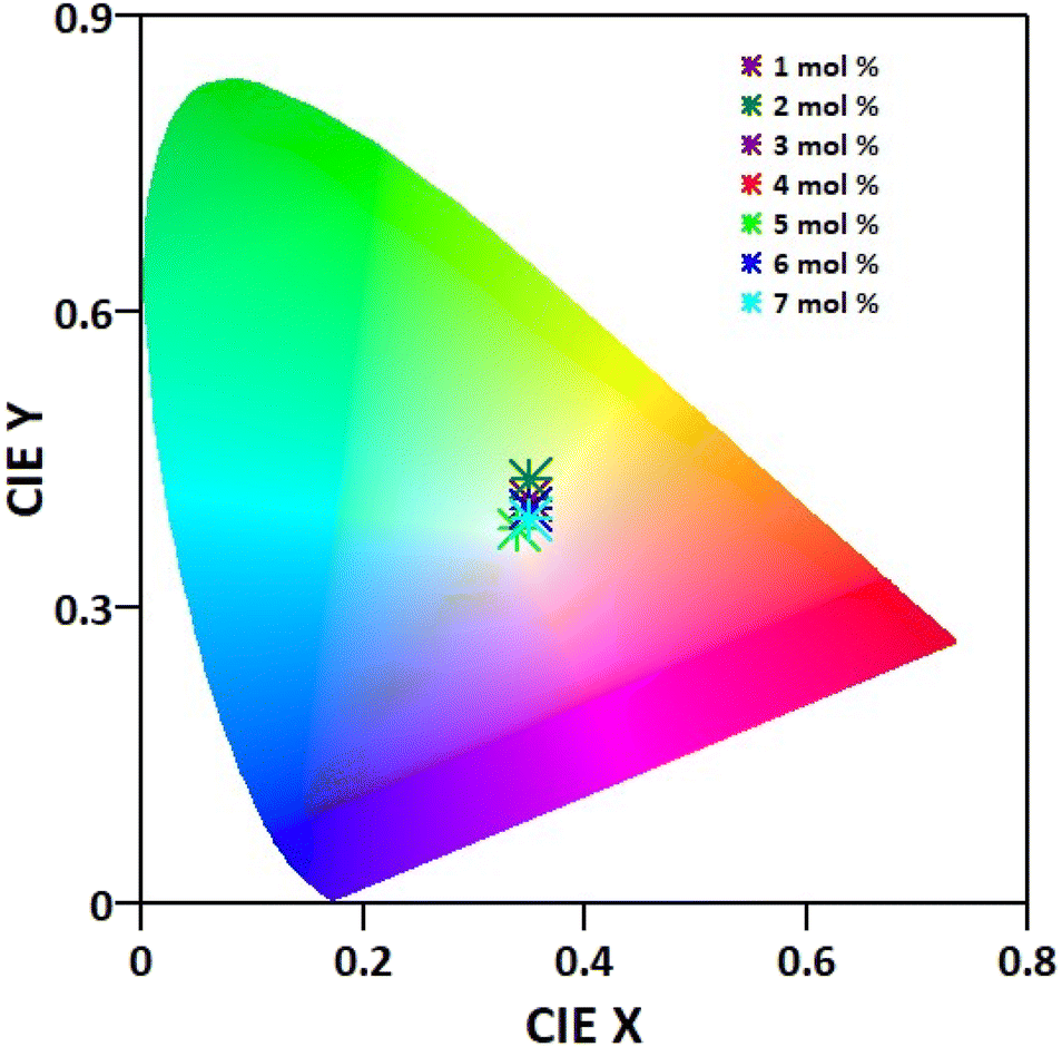
The CIE paradigm of the synthesized Ba(La2−xDyx)ZnO5 phosphor is depicted in Fig. 14. The chromaticity coordinates and other parameters like (u′, v′) (Table 2) were calculated as per the standards of the Commission Internationale de l'Eclairage (CIE). Also employing the McCamy formula,57 the CCT values of the synthesized materials were also computed and were found to vary from 4887 to 5102 K, as shown in Table 1. From the different parameters listed in Table 2, it is evident that the synthesized phosphor material exhibits white emission coordinates. For the optimal doping concentration, these coordinates approximately match the National TV Standards Committee (NTSC) standards (x = 0.333, y = 0.0333) and are in accord with the available literature.8,19,32 These findings suggest that the as-synthesized phosphor materials can be suitable for the generation of UV-excited warm white light emission.
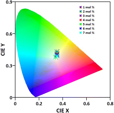 |
| | Fig. 14 Chromaticity diagram depicting the variation in the color coordinates as the concentration of Dy3+ changes from 1 to 7 mol% in the synthesized Ba(La2−xDyx)ZnO5 phosphor. | |
Table 2 Chromaticity coordinates and other parameters correspond to the different concentrations of Dy3+ ions in the host matrices BaLa2ZnO5
| BaLa2−xDyxZnO5 (mol%) |
CIE coordinates (x, y) |
(u′, v′) |
CCT (K) |
| 1 |
0.3549, 0.4145 |
0.1954, 0.5135 |
4887 |
| 2 |
0.3525, 0.4331 |
0.1882, 0.5203 |
4998 |
| 3 |
0.3463, 0.3859 |
0.5006, 0.0158 |
5058 |
| 4 |
0.3463, 0.3923 |
0.1977, 0.5034 |
5061 |
| 5 |
0.3448, 0.3836 |
0.1995, 0.4994 |
5102 |
| 6 |
0.3480, 0.4041 |
0.1958, 0.5074 |
5029 |
| 7 |
0.3508, 0.3971 |
0.1987, 0.5059 |
4951 |
Conclusion
In summary, a Dy3+-activated BaLa2ZnO5 phosphor material emitting a white light was synthesized through a high-temperature solid-state reaction. The XRPD pattern confirms the tetragonal-phase transparency as well as the structural stability of the synthesized nanomaterial when doped with Dy3+ ions. Diffusive reflectance spectra were recorded for computing the bandgap, and it was found that the synthesized phosphor possesses an indirect bandgap of the order of 4.70 eV. It was found that doping does not have a significant impact on the morphology of the particles. Under the excitation and emission wavelengths of 325 nm, 352 nm, and 577 nm, the photoluminescence spectra of targeted samples were analyzed to elucidate the incorporation of Dy3+ ions in the BaLa2ZnO5 host matrix. The emission spectra were found to consist of two sharp blue and yellow bands, which are responsible for the white emission exhibited by the synthesized phosphor material. Furthermore, an upsurge in luminescence intensity was observed until the concentration of Dy3+ reached 5 mol%. After that, the intensity decreases due to the CQ phenomenon initiated by the exchange type of interaction. The thermal stability of the synthesized phosphor was also assessed from temperature-dependent photoluminescence spectra for optimal doping, and it was found that the synthesized phosphor has good thermal stability and possesses an activation energy of 0.29 eV. The decay lifetime of synthesized phosphor ranges in microseconds and shows a decreasing trend with an increase in doping concentrations of Dy3+. The obtained lifetime was fitted with Auzel's model, and a radiative lifetime of the order of 0.23 ms was attained for the stable 4F9/2 quantum mechanical state. Lastly, the CIE coordinates of the synthesized phosphor were found to lie in the white region of the color gamut. The chromaticity coordinates (0.3448, 0.3836) for the optimal doping with CCT 5102 K was found to match well with NTSC standards. In a nutshell, the synthesized phosphor material is capable of being used effectively for fabricating wLEDs for solid-state lighting applications.
Conflicts of interest
There are no conflicts to declare.
Acknowledgements
VK acknowledges the “Fund for Improvement of S&T Infrastructure (FIST)” of the Department of Science & Technology (DST), Government of India (Grant No. SR/FST/PS-1/2021/169), for the financial support provided to the Department of Physics, National Institute of Technology Srinagar, India. This work is also based on the research supported by the South African Research Chairs Initiative of the Department of Science and Technology and the National Research Foundation of South Africa (grand 84415). The financial assistance of the National Research Foundation (NRF) and the University of the Free State towards this research is hereby acknowledged.
References
- J. McKittrick and L. E. Shea-Rohwer, Review: Down Conversion Materials for Solid-State Lighting, J. Am. Ceram. Soc., 2014, 97, 1327–1352, DOI:10.1111/JACE.12943.
- G. B. Nair, H. C. Swart and S. J. Dhoble, A review on the advancements in phosphor-converted light emitting diodes (pc-LEDs): Phosphor synthesis, device fabrication, and characterization, Prog. Mater. Sci., 2020, 109, 100622, DOI:10.1016/J.PMATSCI.2019.100622.
- V. Kumar, S. Som, S. Dutta, S. Das and H. C. Swart, Red-light-emitting inorganic La2CaZnO5 frameworks with high photoluminescence quantum efficiency: Theoretical approach, Mater. Des., 2016, 93, 203–215, DOI:10.1016/j.matdes.2015.12.153.
- H. Hu and W. Zhang, Synthesis and properties of transition metals and rare-earth metals doped ZnS nanoparticles, Opt. Mater., 2006, 28, 536–550, DOI:10.1016/J.OPTMAT.2005.03.015.
- S. Sheoran, V. Singh, S. Singh, S. Kadyan, J. Singh and D. Singh, Down-conversion characteristics of Eu3+ doped M2Y2Si2O9 (M = Ba, Ca, Mg and Sr) nanomaterials for innovative solar panels, Prog. Nat. Sci.: Mater. Int., 2019, 29, 457–465, DOI:10.1016/J.PNSC.2019.07.003.
- U.S. Department of Energy, Energy savings forecast of SSL in general illumination applications, 2019, DOI:10.2172/1374119.
- S. Ray, P. Tadge, S. Dutta, T. M. Chen, G. B. Nair and S. J. Dhoble, Synthesis, luminescence and application of BaKYSi2O7:Eu2+ A new blue-emitting phosphor for near-UV white-light LED, Ceram. Int., 2018, 44, 8334–8343, DOI:10.1016/J.CERAMINT.2018.02.022.
- S. Verma, D. Kumar, S. Dutta, V. Sharma, H. C. Swart and V. Kumar, A novel near white light emitting phosphor KSrYSi2O7:Dy3+ Synthesis, characterization and luminescence properties, Vacuum, 2020, 174, 109179, DOI:10.1016/j.vacuum.2020.109179.
- J. McKenna, A look ahead to the 2015 International Year of Light and Light-based Technologies, J. Opt., 2014, 16, 120201, DOI:10.1088/2040-8978/16/12/120201.
- C. Y. Sun, X. L. Wang, X. Zhang, C. Qin, P. Li, Z. M. Su, D. X. Zhu, G. G. Shan, K. Z. Shao, H. Wu and J. Li, Efficient and tunable white-light emission of metal–organic frameworks by iridium-complex encapsulation, Nat. Commun., 2013, 41(4), 1–8, DOI:10.1038/ncomms3717.
- N. Srinivasa Rao, S. Dhamodaran, A. P. Pathak, P. K. Kulriya, Y. K. Mishra, F. Singh, D. Kabiraj, J. C. Pivin and D. K. Avasthi, Structural studies of Ge nanocrystals embedded in SiO2 matrix, Nucl. Instrum. Methods Phys. Res., Sect. B, 2007, 264, 249–253, DOI:10.1016/J.NIMB.2007.08.094.
- A. J. Kenyon, Recent developments in rare-earth doped materials for optoelectronics, Prog. Quantum Electron., 2002, 26, 225–284, DOI:10.1016/S0079-6727(02)00014-9.
- Y. C. Li, Y. H. Chang, Y. F. Lin, Y. S. Chang and Y. J. Lin, Synthesis and luminescent properties of Ln3+ (Eu3+, Sm3+, Dy3+)-doped lanthanum aluminum germanate LaAlGe2O7 phosphors, J. Alloys Compd., 2007, 439, 367–375, DOI:10.1016/J.JALLCOM.2006.08.269.
- S. Som, P. Mitra, V. Kumar, V. Kumar, J. J. Terblans, H. C. Swart and S. K. Sharma, The energy transfer phenomena and colour tunability in Y2O2S:Eu3+/Dy3+ micro-fibers for white emission in solid state lighting applications, Dalton Trans., 2014, 43, 9860–9871, 10.1039/C4DT00349G.
- A. K. Ambast, J. Goutam, S. Som and S. K. Sharma, Ca1−x−yDyxKyWO4: A novel near UV converting phosphor for white light emitting diode, Spectrochim. Acta, Part A, 2014, 122, 93–99, DOI:10.1016/J.SAA.2013.11.032.
- S. H. Park, K. H. Lee, S. Unithrattil, H. S. Yoon, H. G. Jang and W. Bin Im, Melilite-structure CaYAl3O7:Eu3+ phosphor: Structural and optical characteristics for near-UV LED-based white light, J. Phys. Chem. C, 2012, 116, 26850–26856, DOI:10.1021/JP307192Y/ASSET/IMAGES/LARGE/JP-2012-07192Y_0010.JPEG.
- D. Navami, R. B. Basavaraj, S. C. Sharma, B. Daruka Prasad and H. Nagabhushana, Rapid identification of latent fingerprints, security ink and WLED applications of CaZrO3:Eu3+ fluorescent labelling agent fabricated via bio-template assisted combustion route, J. Alloys Compd., 2018, 762, 763–779, DOI:10.1016/J.JALLCOM.2018.05.016.
- P. Sehrawat, A. Khatkar, P. Boora, M. Kumar, R. K. Malik, S. P. Khatkar and V. B. Taxak, Emanating cool white light emission from novel down-converted SrLaAlO4:Dy3+ nanophosphors for advanced optoelectronic applications, Ceram. Int., 2020, 46, 16274–16284, DOI:10.1016/J.CERAMINT.2020.03.184.
- N. Hussain, S. Rubab and V. Kumar, Spectroscopic characterizations and investigation of Judd-Ofelt intensity parameters of Dy3+-doped Ba2La8(SiO4)6O2 near white light emitting phosphor, Ceram. Int., 2023, 49, 15341–15348, DOI:10.1016/j.ceramint.2023.01.118.
- F. Li, L. Li, C. Guo, T. Li, H. Mi Noh and J. H. Jeong, Up-conversion luminescence properties of Yb3+-Ho3+ co-doped CaLa2ZnO5, Ceram. Int., 2014, 40, 7363–7366, DOI:10.1016/j.ceramint.2013.12.080.
- Q. Ning, C. Zhou and Y. Shi, Effect of Eu3+ doping on ZnWO4 phosphors luminescent properties and study of J-O theory, J. Solid State Chem., 2020, 290, 121458, DOI:10.1016/J.JSSC.2020.121458.
- A. H. Wako, F. B. Dejene and H. C. Swart, Combustion synthesis, characterization and luminescence properties of barium aluminate phosphor, J. Rare Earths, 2014, 32, 806–811, DOI:10.1016/S1002-0721(14)60145-9.
- P. M. Maleka, L. Reddy, T. J. Nkosi, A. Balakrishna, R. E. Kroon, H. C. Swart and O. M. Ntwaeaborwa, Structural and morphological characterization of photoluminescent cerium-doped near UV-blue sodium ortho-phosphate phosphors, J. Lumin., 2020, 226, 117409, DOI:10.1016/J.JLUMIN.2020.117409.
- A. Balakrishna, L. Reddy, O. M. Ntwaeaborwa and H. C. Swart, Remarkable influence of alkaline earth ions on the enhancement of fluorescence from Eu3+ ion doped in sodium ortho-phosphate phosphors, J. Mol. Struct., 2020, 1203, 127375, DOI:10.1016/J.MOLSTRUC.2019.127375.
- S. S. Pitale, M. Gohain, I. M. Nagpure, O. M. Ntwaeaborwa, B. C. B. Bezuidenhoudt and H. C. Swart, A comparative study on structural, morphological and luminescence characteristics of Zn3(VO4)2 phosphor prepared via hydrothermal and citrate-gel combustion routes, Phys. B, 2012, 407, 1485–1488, DOI:10.1016/J.PHYSB.2011.09.067.
- A. K. Kunti, L. Ghosh, S. K. Sharma and H. C. Swart, Synthesis and luminescence mechanism of white light emitting Eu3+ doped CaZnV2O7 phosphors, J. Lumin., 2019, 214, 116530, DOI:10.1016/J.JLUMIN.2019.116530.
- L. Li, C. Guo, S. Jiang, D. K. Agrawal and T. Li, Green up-conversion luminescence of Yb3+-Er3+ co-doped CaLa2ZnO5 for optically temperature sensing, RSC Adv., 2014, 4, 6391–6396, 10.1039/c3ra47264g.
- H. R. Shih, Y. Y. Tsai, K. T. Liu, Y. Z. Liao and Y. S. Chang, The luminescent properties of Pr3+ ion-doped BaY2ZnO5 phosphor under blue light irradiation, Opt. Mater., 2013, 35, 2654–2657, DOI:10.1016/j.optmat.2013.08.007.
- V. Singh, P. Halappa, N. Singh, M. S. Pathak, C. Shivakumara and V. Natarajan, EPR and Optical Properties of UV-B Radiation-Emitting Gd3+ -Doped BaLa2ZnO5 Host Prepared by Sol–Gel Method, J. Electron. Mater., 2019, 48, 3415–3422, DOI:10.1007/S11664-019-07122-9/METRICS.
- P. Sehrawat, R. K. Malik, M. Sheoran and R. Punia, Generation of cost-effective conventional-combustion derived novel green-luminous BaLa2ZnO5:Er3+ nanomaterials for high quality illumination in WLEDs and solar-cells, Chem. Phys. Lett., 2021, 777, 138752, DOI:10.1016/j.cplett.2021.138752.
- J. Song, X. Zhang, N. Huang, H. Dou, B. Chen, X. Tian, C. Wang and L. Wu, Luminescence properties and thermometric performance of Bi3+/Sm3+-codoped BaLa2ZnO5 phosphors, Ceram. Int., 2023, 49, 15229–15236, DOI:10.1016/j.ceramint.2023.01.105.
- P. Sehrawat, R. K. Malik, R. Punia, S. Maken and N. Kumari, Ecofriendly synthesis and white light-emitting properties of BaLa2ZnO5:Dy3+ nanomaterials for lighting application in NUV-WLEDs and solar cells, Chem. Phys. Lett., 2022, 792, 139399, DOI:10.1016/J.CPLETT.2022.139399.
- V. Singh, G. Lakshminarayana and A. Wagh, Photoluminescence Investigation on Green-Emitting Tb3+-Doped BaLa2ZnO5 Nanophosphors, J. Electron. Mater., 2020, 49, 510–517, DOI:10.1007/s11664-019-07734-1.
- V. Singh, G. Lakshminarayana, D. E. Lee, J. Yoon and T. Park, Luminescence properties of reddish orange emitting BaLa2ZnO5:Sm3+ phosphor prepared by citric based sol-gel synthesis, Solid State Sci., 2019, 98, 106042, DOI:10.1016/J.SOLIDSTATESCIENCES.2019.106042.
- H. Dahiya, M. Dalal, J. Dalal, V. B. Taxak, S. P. Khatkar and D. Kumar, Synthesis and luminescent properties of Tb3+ doped BaLa2ZnO5 nanoparticles, Mater. Res. Bull., 2018, 99, 86–92, DOI:10.1016/j.materresbull.2017.11.005.
- J. Xie, L. Mei, L. Liao, M. Guan and H. Liu, Synthesis and up-conversion luminescence properties of Ho3+, Yb3+ co-doped BaLa2ZnO5, J. Phys. Chem. Solids, 2015, 83, 152–156, DOI:10.1016/J.JPCS.2015.04.006.
- S. Gai, H. Zhu, P. Gao, C. Zhou, Z. Kong, M. S. Molokeev, Z. Qi, Z. Zhou and M. Xia, Structure analysis, tuning photoluminescence and enhancing thermal stability on Mn4+-doped La2-xYxMgTiO6 red phosphor for agricultural lighting, Ceram. Int., 2020, 46, 20173–20182, DOI:10.1016/j.ceramint.2020.05.095.
- P. Sehrawat, A. Khatkar, S. Devi, A. Hooda, S. Singh, R. K. Malik, S. P. Khatkar and V. B. Taxak, An effective emission of characteristic cool white light from Dy3+ doped perovskite type SrLa2Al2O7 nanophosphors in single-phase pc WLEDs, Chem. Phys. Lett., 2019, 737, 136842, DOI:10.1016/j.cplett.2019.136842.
- P. Sehrawat, R. K. Malik, S. P. Khatkar and V. B. Taxak, Highly efficient green-glimmering Y3Al5O12:Er3+ NPs for next generation electro-optic appliances, mainly white-LEDs and solar-cells, Chem. Phys. Lett., 2021, 773, 138592, DOI:10.1016/J.CPLETT.2021.138592.
- P. Sehrawat, R. K. Malik, R. Punia, M. Sheoran, S. Singh and M. Kumar, New Ba2YAlO5:Dy3+ nanomaterials for WLEDs: Propellant combustion synthesis and photometric features for enhanced emission of cool-white light under NUV excitation, Chem. Phys. Lett., 2021, 781, 138985, DOI:10.1016/j.cplett.2021.138985.
- P. Sehrawat, S. P. Khatkar, I. Jin Kim, R. K. Malik, P. Chhillar and V. B. Taxak, Realization of tricolor luminescence from novel Sr5Al2O8:Sm3+, Er3+& Dy3+ nanomaterials for advanced photonic applications, Chem. Phys. Lett., 2021, 762, 138134, DOI:10.1016/J.CPLETT.2020.138134.
- P. Sehrawat, R. K. Malik, R. Punia, M. Sheoran, N. Kumari, S. P. Khatkar and V. B. Taxak, Luminescence tuning and structural analysis of new BaYAlZn3O7:Sm3+ nanomaterials with excellent performance for advanced optoelectronic appliances, J. Mater. Sci.: Mater. Electron., 2021, 32, 15930–15943, DOI:10.1007/s10854-021-06144-6.
- T. Samanta, A. E. Praveen and V. Mahalingam, Host sensitized intense infrared emissions from Ln3+ doped GdVO4 nanocrystals: ranging from 950 nm to 2000 nm, J. Mater.
Chem. C, 2018, 6, 4878–4886, 10.1039/C8TC00841H.
- G. Blasse, Energy transfer between inequivalent Eu2+ ions, J. Solid State Chem., 1986, 62, 207–211, DOI:10.1016/0022-4596(86)90233-1.
- J. Zhao, H. Gao, H. Xu, Z. Zhao, H. Bu, X. Cao, L. He, Z. Yang and J. Sun, Structure and photoluminescence of Eu3+ doped Sr2InTaO6 red phosphor with high color purity, RSC Adv., 2021, 11, 8282–8289, 10.1039/D1RA00165E.
- Q. Meng, B. Chen, W. Xu, Y. Yang, X. Zhao, W. Di, S. Lu, X. Wang, J. Sun, L. Cheng, T. Yu and Y. Peng, Size-dependent excitation spectra and energy transfer in Tb3+-doped Y2O3 nanocrystalline, J. Appl. Phys., 2007, 102, 093505, DOI:10.1063/1.2803502.
- Y. Tian, B. Chen, B. Tian, R. Hua, J. Sun, L. Cheng, H. Zhong, X. Li, J. Zhang, Y. Zheng, T. Yu, L. Huang and Q. Meng, Concentration-dependent luminescence and energy transfer of flower-like Y2(MoO4)3:Dy3+ phosphor, J. Alloys Compd., 2011, 509, 6096–6101, DOI:10.1016/J.JALLCOM.2011.03.034.
- H. Shihua and L. Liren, Concentration dependence of sensitizer fluorescence intensity in energy transfer, Chin. J. Lumin., 1990, 11, 1–7 Search PubMed.
- S. Dutta, S. Som and S. K. Sharma, Luminescence and photometric characterization of K+ compensated CaMoO4:Dy3+ nanophosphors, Dalton Trans., 2013, 42, 9654–9661, 10.1039/C3DT50780G.
- B. R. Judd, Optical absorption intensities of rare-earth ions, Phys. Rev., 1962, 127, 750–761, DOI:10.1103/PhysRev.127.750.
- G. S. Opelt, Intensities of Crystal Spectra of Rare-Earth Ions, J. Chem. Phys., 2004, 37, 511, DOI:10.1063/1.1701366.
- S. Dutta, S. Som and S. K. Sharma, Excitation spectra and luminescence decay analysis of K+ compensated Dy3+ doped CaMoO4 phosphors, RSC Adv., 2015, 5, 7380–7387, 10.1039/C4RA12447B.
- W. Luo, J. Liao, R. Li and X. Chen, Determination of Judd–Ofelt intensity parameters from the excitation spectra for rare-earth doped luminescent materials, Phys. Chem. Chem. Phys., 2010, 12, 3276–3282, 10.1039/B921581F.
- M. L. Meena, C. H. Lu, S. Som, R. Chaurasiya and S. D. Lin, Highly efficient and thermally stable Eu3+ activated phosphate based phosphors for wLEDs: An experimental and DFT study, J. Alloys Compd., 2022, 895, 162670, DOI:10.1016/j.jallcom.2021.162670.
- S. Dutta, S. Som, M. L. Meena, R. Chaurasiya and T. M. Chen, Multisite-Occupancy-Driven Intense Narrow-Band Blue Emission from Sr5SiO4Cl6:Eu2+ Phosphor with Excellent Stability and Color Performance, Inorg. Chem., 2020, 59, 1928–1939, DOI:10.1021/ACS.INORGCHEM.9B03222/SUPPL_FILE/IC9B03222_SI_001.PDF.
- H. Zhou, Y. Jin, M. Jiang, Q. Wang and X. Jiang, A single-phased tunable emission phosphor MgY2Si3O10:Eu3+,Bi3+ with efficient energy transfer for white LEDs, Dalton Trans., 2014, 44, 1102–1109, 10.1039/C4DT02114B.
- S. Tanabe, J. Kang, T. Hanada and N. Soga, Yellow/blue luminescences of Dy3+-doped borate glasses and their anomalous temperature variations, J. Non-Cryst. Solids, 1998, 239, 170–175, DOI:10.1016/S0022-3093(98)00734-0.
|
| This journal is © The Royal Society of Chemistry 2023 |
Click here to see how this site uses Cookies. View our privacy policy here. 
 Open Access Article
 This Open Access Article is licensed under a Creative Commons Attribution-Non Commercial 3.0 Unported Licence
 ab and
Vijay Kumar
ab and
Vijay Kumar