
 Open Access Article
 This Open Access Article is licensed under a Creative Commons Attribution-Non Commercial 3.0 Unported Licence
Coconut power: a sustainable approach for the removal of Cr6+ ions using a new coconut-based polyurethane foam/activated carbon composite in a fixed-bed column
Tomas Ralph B. Tomon ab,
Renz John R. Estradaa,
Rubie Mae D. Fernandezab,
Rey Y. Capangpanganc,
Alona A. Lubguband,
Gerard G. Dumancase,
Arnold C. Algunoag,
Roberto M. Malaluanaf,
Hernando P. Bacosaab and
Arnold A. Lubguban*af
ab,
Renz John R. Estradaa,
Rubie Mae D. Fernandezab,
Rey Y. Capangpanganc,
Alona A. Lubguband,
Gerard G. Dumancase,
Arnold C. Algunoag,
Roberto M. Malaluanaf,
Hernando P. Bacosaab and
Arnold A. Lubguban*af
aCenter for Sustainable Polymers, Mindanao State University – Iligan Institute of Technology, 9200 Iligan City, Philippines. E-mail: arnold.lubguban@g.msuiit.edu.ph
bGraduate Program of Environmental Science, Department of Biological Sciences, Mindanao State University – Iligan Institute of Technology, 9200 Iligan City, Philippines
cDepartment of Physical Sciences and Mathematics, Mindanao State University at Naawan, 9023 Naawan, Philippines
dDepartment of Mathematics, Statistics, and Computer Studies, University of the Philippines, Rural High School, Paciano Rizal Bay, 4033 Laguna, Philippines
eDepartment of Chemistry, The University of Scranton, Scranton, PA 18510, USA
fDepartment of Chemical Engineering and Technology, Mindanao State University – Iligan Institute of Technology, 9200 Iligan City, Philippines
gDepartment of Physics, Mindanao State University – Iligan Institute of Technology, 9200 Iligan City, Philippines
First published on 12th July 2023
Abstract
To attain efficient removal of hexavalent chromium (Cr6+) from aqueous solutions, a novel polyurethane foam-activated carbon (PUAC) adsorbent composite was developed. The composite material was synthesized by the binding of coconut shell-based activated carbon (AC) onto a coconut oil-based polyurethane matrix. To thoroughly characterize the physicochemical properties of the newly developed material, various analytical techniques including FTIR spectroscopy, SEM, XRD, BET, and TGA analyses were conducted. The removal efficiency of the PUAC composite in removing Cr6+ ions from aqueous solutions was evaluated through column experiments with the highest adsorption capacity of 28.41 mg g−1 while taking into account variables such as bed height, flow rate, initial Cr6+ ion concentration, and pH. Experimental data were fitted using Thomas, Yoon-Nelson, and Adams-Bohart models to predict the column profiles and the results demonstrate high breakthrough and exhaustion time dependence on these variables. Among the obtained R2 values of the models, a better fit was observed using the Thomas and Yoon-Nelson models, indicating their ability to effectively predict the adsorption of Cr6+ ions in a fixed bed column. Significantly, the exhausted adsorbent can be conveniently regenerated without any noteworthy loss of adsorption capability. Based on these findings, it can be concluded that this new PUAC composite material holds significant promise as a potent sorbent for wastewater treatment backed by its excellent performance, cost-effectiveness, biodegradability, and outstanding reusability.
1. Introduction
The Earth has continuously faced significantly challenging threats, including global warming, air pollution, rising human population, and water contamination.1 Today, the accessibility to clean drinking water has become scarce in most parts of the world. This has drastically affected human civilization's environmental, social, and economic conditions.2 Data presented by the World Health Organization (WHO) and the United Nations Children's Fund (UNICEF) in 2017 estimated that only 71% of the world population has access to safe drinking water. A study conducted by the Global Burden of Diseases (GBD) in the same year shows that unsafe water source ranks 15th in the causes and risk factors for death and diseases, responsible for about 1.23 million annual deaths worldwide, and approximately 5507 annual deaths in the Philippines. Excessive release of pollutants such as toxic metal ions,3 dye effluents,1 and excessive use of pesticides and inorganic fertilizers4 into waterways from various industries contributes significantly to pollution and poses an imminent threat to living organisms.1Heavy metals are metals with high densities and are toxic even at low concentrations. These pollutants enter various ecosystems through different natural and anthropogenic activities.5 Global industrialization6 and the rapid increase in the world population enabled hazardous materials to spread into the environment at unprecedented speed. Building materials, mining operations, leather tanning, and electronics are some of the few industries utilizing heavy metals.7,8 Due to a serious lack of compliance with the regulations with regards to discharges8 of industrial processes, heavy metals spread into the environment9 through untreated wastewater10 in the form of solids, liquids, and gases. It is estimated that two million tons of sewage and other effluents are being drained into the bodies of water daily.2,11 Heavy metals are known to be human carcinogens and are non-biodegradable.6,12 As such, heavy metals tend to bioaccumulate and produce genotoxic, carcinogenic, and mutagenic effects in plants and animals, which in turn, can be assimilated by the human body through ingestion, making them a more significant threat as their exposure continues to grow, especially in less developed countries.2
Chromium is one of the most common heavy metals that pollute the environment, apart from arsenic, cadmium, copper, nickel, lead, and mercury. It is known for its anti-corrosive properties and is the primary additive in stainless steel manufacturing industries. It is used primarily in wood preservation, leather tanning, metal finishing, and pigmentation. Chromium exists and enters different environmental media via two oxidation states: trivalent (Cr3+) and hexavalent (Cr6+) chromium, stable13–15 yet considered toxic and carcinogenic pollutants. The trivalent state of chromium that occurs in nature is essential for glucose metabolism in mammals.16 The hexavalent state is considered the most toxic state among the chromium species because of its transportability and absorbability within the cell. Cr6+ is reduced through metabolic processes where genotoxic damage and other forms of toxicity are generated.17 Because of this, international and national legislative bodies standardized the permissible tolerance limits for different types of heavy metals that are environmentally safe. This mandates the effective treatment of heavy metals and other pollutants before they can be discharged into the environment.
Various conventional treatment methods, such as chemical precipitation, ion exchange, evaporation, and biological treatment were reported to remove Cr6+ ions from water effectively.5,18,19 However, these methods have several drawbacks including high energy consumption, high operational cost and maintenance, high chemical input, and the possibility of generating secondary pollutants. Adsorption, on the other hand, has been considered one of the promising wastewater treatment methods20,21 because of its simple application, low operational cost, reusability, low energy consumption, and good removal performance. Because of this, the focus was shifted towards an adsorption-based approach, wherein characteristics mainly depend on high porosity and surface-charge distribution of the adsorbent.1 As a result, recent studies related to the development of technologies that are sustainable and efficient in adsorbing heavy metals from aqueous solutions continue to take place.
Commercial activated carbon (AC) is the most commonly utilized adsorbent for wastewater treatment. However, it has limiting factors as it is inherently costly, non-renewable, challenging to recover, and tends to break down into pieces and finer fragments, making its practical deployment difficult. Additionally, synthetic polymers are also commonly employed in wastewater treatment processes22 in the form of polyurethane (PU) foams. Due to their excellent porosity distribution and high surface area, PU foams are known for their many applications in various fields, such as appliances, industrial, medical, and filtration systems. Despite this, the polyols used for the production of PU foams are derived from non-renewable resources and are expected to last for only a few more years.23 Thus, choosing the right raw material is critical, and favoring bio-based materials as an alternative source for producing PU foams is essential.24
Biopolyols are the potential alternative raw materials for the sustainable production of rigid PU foam, but in order to do so, polyols would require a relatively high hydroxyl value.17 Vegetable oils do not naturally contain hydroxyl groups and are less suitable reactants in polyols production than other substrates unless chemical modifications are made.18 Hydroxyl groups are therefore chemically generated from vegetable oils, the number of which is dependent on the nature and triglyceride structure of the specific oil. Unsaturated vegetable oils are typically modified by double bond epoxidation and ring-opening reactions with alcohols and haloacids.5,6,19 Saturated vegetable oils usually undergo transesterification and amidation reactions.11,20–23 However, previous studies on saturated vegetable oil modification reported polyols with low hydroxyl values, which necessitates petroleum-based polyol replacement to be effective for use in rigid PU foam formation.24,25 This major limitation is attributed to the mostly unsaturated composition of vegetable oil triglycerides making it less capable of hydroxyl functionalization.6
Coconut is one of the most abundant and inexpensive commodities available in the Philippines and its neighboring countries. Alongside the production of goods from coconut for exportation is the increased production of wastes and their by-products. To solve this difficulty, the present study was geared to address this problem and investigate the utilization of coconut-based polyurethane foam-activated carbon (PUAC) composites for the effective removal of Cr6+ contaminants in wastewater bodies. These coconut-oil-based PUAC are designed to be thermally and chemically stable,25 and inexpensive to generate due to their raw materials being considered as waste or low-value by-products. Additionally, the functional groups present in the composite material was analysed using fourier transform infrared spectrometer (FTIR). The enhancement of the surface area of the composite was characterized using scanning electron microscopy (SEM), and surface area analyzer. The thermal stability and microstructural properties were determined using a thermal gravimetric analysis (TGA), and X-ray diffraction (XRD) analyses, respectively.
Moreover, the effects of several operational parameters, including bed height, flow rate, influent Cr6+ concentration, pH, and reusability studies were examined and the experimental data were fitted using various models to predict the breakthrough curves for the dynamic adsorption of Cr6+ onto the PUAC foam composites.
2 Experimental
2.1 Materials
The AC sourced from coconut shells was supplied by the Philippine Japan Active Carbon. AC was pulverized and sieved using a 50-mesh screen to attain a uniform size. The potassium dichromate (K2Cr2O7) used in this study was of analytical grade and was provided by Caraga State University (CSU, Butuan City, Philippines). Materials such as the catalyst (Polycat® 8) and surfactant (INV® 690) were obtained from Sigma-Aldrich Chemicals, Philippines. The polyol component used was a coconut oil-based polyol (in-house, patent-pending) blended with a fraction of petroleum-based polyol (Voranol® 4701, polyether polyol). Voranol® 4701, a stabilizer, dispersant silicon oil, and methylene diphenyl diisocyanate (MDI, PAPI 135 SH), were provided by Chemrez Technologies, Inc. (Quezon City, Philippines). The abaca fiber used as a cellular reinforcement was locally sourced in Iligan City, Philippines.2.2 Synthesis of the coconut oil-based polyol
The coconut oil-based polyol used in this study was previously developed26 through a sequential process of (1) breaking down coconut triglycerides into its component acylglycerol by-products (180 °C, 3 h) under constant stirring, followed by a (2) polyol-forming process (200 °C, 3 h). The polyol product was then allowed to cool down at room temperature and stored in a sealed glass container.2.3 Preparation of adsorbate solution
A stock solution of 1000 ppm of Cr6+ was prepared by dissolving 2.8286 g of K2Cr2O7 in 1000 mL distilled water and stored in amber glass. This study obtained the required concentrations by successive dilution of the standard stock solution (0–300 ppm). Adsorption experiments at different concentrations of Cr6+ were performed using the prepared solutions.2.4 Preparation of the composite PU foam
To synthesize the foam, A-side (MDI) and B-side (polyol and formulation components) materials were mixed using the free-rise method.27 To impregnate the PU foam with AC, a reaction occurred between the components, wherein one NCO end of the MDI reacted with the surface –OH group of the AC, while the other end reacted with the OH functional groups in the polyol chain.28The polyol mixture (B-side components) containing the polyols, surfactant, and catalyst was mixed with a substantial amount of activated carbon at 1000 rpm for 60 seconds to produce the polyol mixture. A stoichiometric amount of MDI (A-side component) was then added to the reaction mixture with the same rotation speed for another 15 seconds to obtain a homogeneous mixture. Once homogenized, the mixture was left undisturbed and was allowed to rise freely. The resulting expanded polymer was then continuously cured in an oven at 60 °C for two (2) hours.29 After the curing process, the foam samples were set aside overnight before cutting into a 0.5 × 0.5 × 0.5 cm cube dimensions and were consequently tested.
2.5 Column adsorption studies
Fig. 1 depicts the actual layout of the fixed-bed column setup. The adsorption experiment of the adsorbate solution was carried out in a continuous experimental system on a laboratory scale made of an acrylic column with an inner dimension of 2 cm in diameter and 20 cm in height. The entire process was completed at room temperature. One (1) g cm−1 of the PUAC composite was weighed and packed into the column. The column was supported with a 3D-printed funnel on both ends to ensure stability and proper distribution of the inlet solution, as seen in the figure.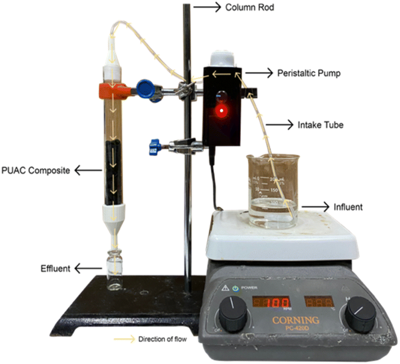 | ||
| Fig. 1 Actual setup of the fixed-bed column. | ||
The adsorbent was then added from the top of the column and carefully packed until the desired height was attained. The solution containing the desired concentration of Cr6+ ions was stirred constantly at 100 rpm and pumped through the continuous system in a down-flow mode with the aid of a peristaltic pump. Aliquots were collected at different time intervals, and the concentration of the output solution was measured spectrophotometrically using a UV-Vis spectrometer at 313 nm wavelength (Thermo Fisher Scientific Genesys 10s, MA USA).30
Experiments were performed to examine the impact of flow rate and bed height on the adsorption of Cr6+ ions onto the PUAC. The tests were conducted at three (3) flow rates (4, 6, and 8 mL min−1), three (3) bed heights (5, 10, and 15 cm), and three (3) pH values (2, 4, and 6), respectively while keeping other variables constant. Following the optimization of flow rate, bed height, and pH, the study assessed the impact of metal ion concentration on adsorption efficiency at concentrations of 50, 100, and 200 mg L−1.
The fixed-bed setup experiment was carried out until the saturation point at which no adsorption of Cr6+ ions is detected. The breakthrough curves were established as it is a vital characteristic in determining a fixed-bed column's dynamic response.3 Breakthrough curves are expressed by Ct/C0 against time t.
2.6 Column data analysis
The breakthrough curve represents the performance of the fixed-bed column. The total mass adsorbed, qtotal, at certain conditions against time t and was calculated using eqn (1).
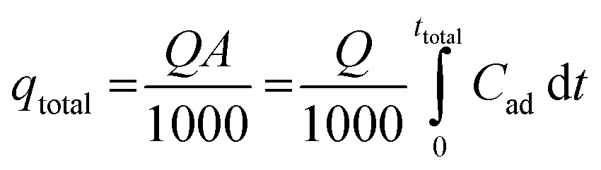 | (1) |
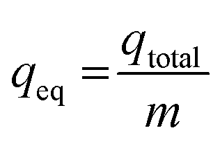
The maximum metal uptake, qeq, of the adsorbent using the continuous system was calculated using eqn (2). Finally, the total volume of the effluent, Veff, was calculated using eqn (3).
 | (2) |
| Veff = Qttotal | (3) |
2.7 Column breakthrough curve modeling
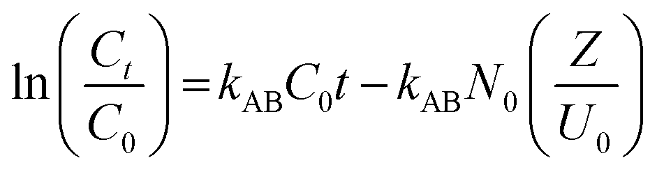
Several theoretical adsorption models have been applied to project the dynamic adsorption behavior of the residual Cr6+ ions in a fixed-bed column. In this work, three of the most commonly applied mathematical models, namely the Adams-Bohart model, Thomas model, and Yoon-Nelson model, were used to establish fit with the experimental data.The Adams-Bohart31 model is grounded on the surface reaction theory and describes the relationship between C0/Ct against time t in a continuous system and assumes that equilibrium is not attained instantaneously.3 The linear form of the Adams-Bohart model can be demonstrated as:
 | (4) |
In designing a continuous adsorption column, determining the maximum adsorption capacity, qTh, is essential. The Thomas32 model is one of the most common tools. This model assumes that mass transfer at the interface controls adsorption rather than chemical interactions between molecules.33 The linear form of the equation is expressed as:
 | (5) |
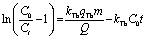
The Yoon-Nelson34 model is also a common tool in determining the breakthrough and saturation time of the continuous system. The model assumes that the adsorption rate of each adsorbate is proportional to the rate of decrease in adsorption.35 The model is given as
 | (6) |
2.8 Characterization
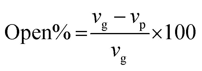
To study the functional groups and the surface morphology of the synthesized PUAC, the samples were characterized using FTIR (Shimadzu ATR-FTIR IRTracer-100, Kyoto, JPN), SEM (JEOL JSM-6510LA, Tokyo, JPN). The specific surface area and pore diameter of the adsorbent were measured by utilizing a surface area analyzer (Microtrac BELSORP MINI X, Osaka, JPN). The thermal degradation profile was analyzed using TGA (Shimadzu DTG 60H, Kyoto, JPN) with nitrogen ambient (flow rate 20 mL min−1) and a temperature rate of 10 °C min−1. All pH values were measured using a digital pH meter (KEM AT-710, Kyoto, JPN). The XRD patterns were recorded with a Cu Kα radiation source (40 kV and 30 mA) in a 3–60° 2θ range with a speed of 0.02° 2θ/0.60s (Shimadzu XRD Maxima 7000, JPN). The open-cell content of the foam was obtained using a pycnometer (Quantachrome ULTRAPYC 1200e, FL USA) and calculated as:
 | (7) |
3 Results and discussion
3.1 Characterization of the adsorbent
![[double bond, length as m-dash]](https://www.rsc.org/images/entities/char_e001.gif) O bonds present in the region, respectively. At ∼1599 cm−1, the peak intensity specific to CC was reduced in PUAC. This indicates that the NCO functionality of MDI had reacted with the surface hydroxyls of AC through –NCO and –OH reaction, forming the carbamate bond.26,36 Further, the peak between 1070 cm−1 and 1132 cm−1 and that of the N–H peak at 3357 cm−1 became noticeably weak compared to the blank PU. The observed weak peak intensities imply that hydrogen bonding occurred, confirming the incorporation of AC into the composite material. This is attributed to the heterogeneity of the carbonyl environments, which substantiates the linkage between the AC and the polymer.28 Finally, the evident presence of the carboxylic (1730 cm−1) and hydroxylic (3357 cm−1) functional groups acted as proton donors, and are ultimately responsible for the uptake of heavy metals.35,36
O bonds present in the region, respectively. At ∼1599 cm−1, the peak intensity specific to CC was reduced in PUAC. This indicates that the NCO functionality of MDI had reacted with the surface hydroxyls of AC through –NCO and –OH reaction, forming the carbamate bond.26,36 Further, the peak between 1070 cm−1 and 1132 cm−1 and that of the N–H peak at 3357 cm−1 became noticeably weak compared to the blank PU. The observed weak peak intensities imply that hydrogen bonding occurred, confirming the incorporation of AC into the composite material. This is attributed to the heterogeneity of the carbonyl environments, which substantiates the linkage between the AC and the polymer.28 Finally, the evident presence of the carboxylic (1730 cm−1) and hydroxylic (3357 cm−1) functional groups acted as proton donors, and are ultimately responsible for the uptake of heavy metals.35,36
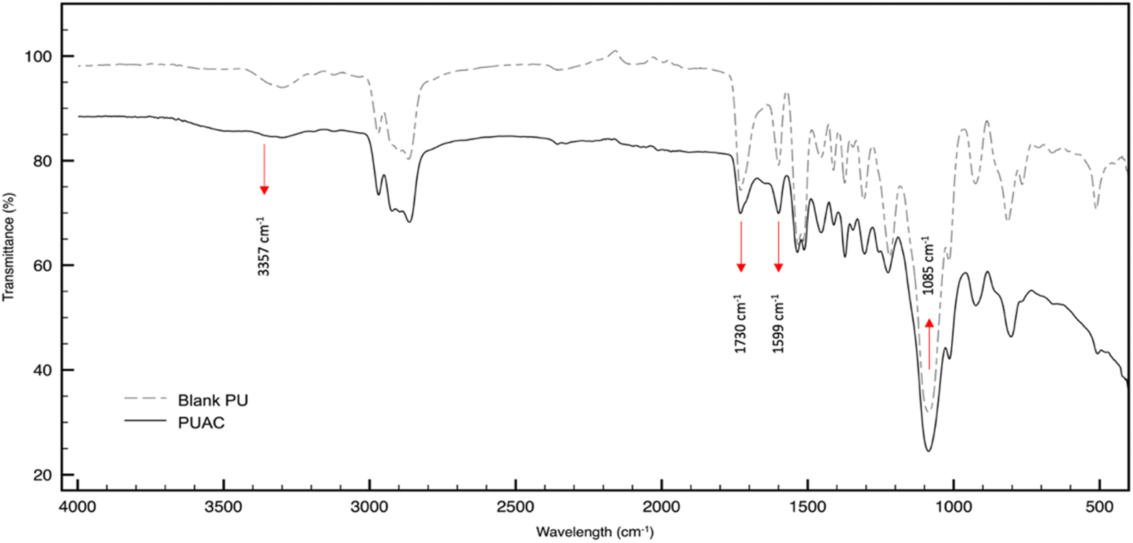 | ||
| Fig. 2 FTIR spectra of a blank polyurethane foam against the composite foam. | ||
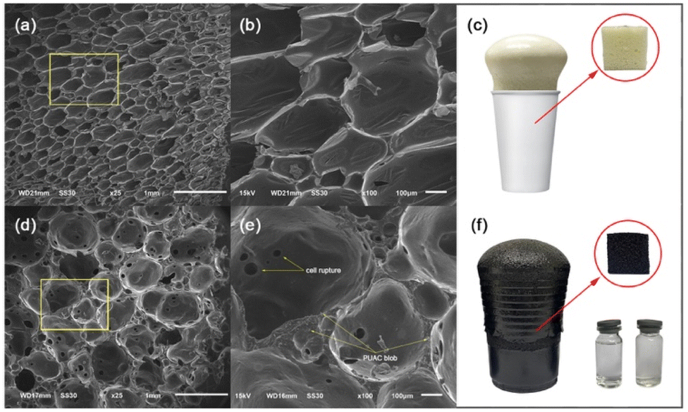 | ||
| Fig. 3 SEM image of (a) blank polyurethane (PU, 1 mm), (b) blank PU (100 μm), (c) blank PU cup foam, (d) polyurethane foam-activated carbon (PUAC, 1 mm), (e) PUAC (100 μm), (f) PUAC cup foam and resulting clear effluent after column adsorption. | ||
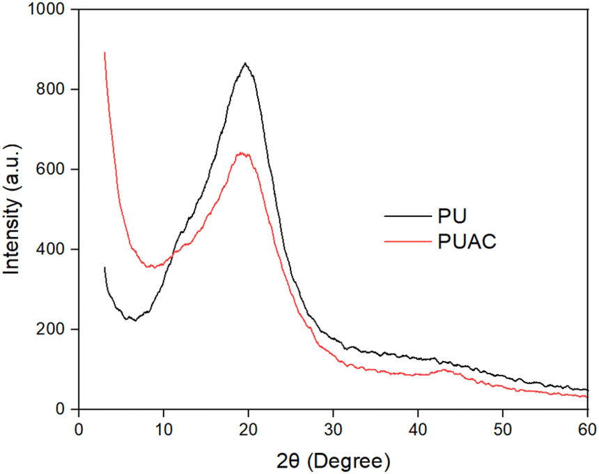 | ||
| Fig. 4 XRD profile of a blank polyurethane (PU) and polyurethane foam-activated carbon composite. | ||
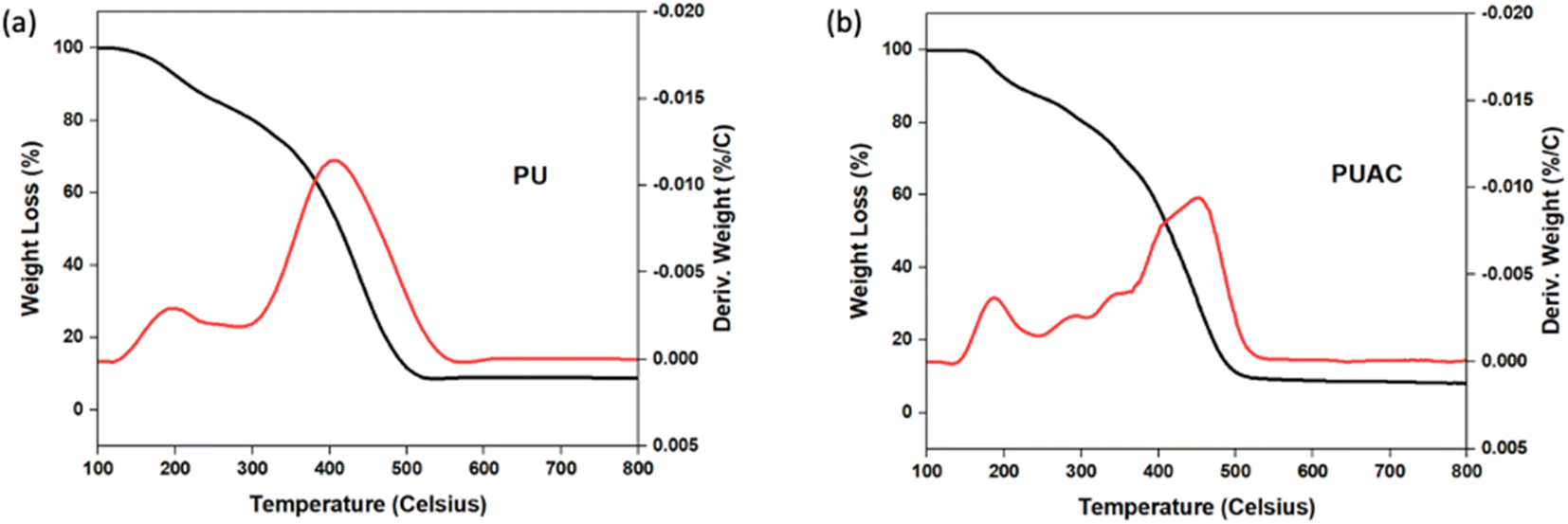 | ||
| Fig. 5 TGA–DTG curves of (a) polyurethane (PU) and (b) polyurethane foam-activated carbon. | ||
3.2 Fixed-bed column studies
Results revealed that as the bed height was increased from 5 cm to 15 cm, exhaustion time also increased from 180 to 300 min, as seen in the breakthrough curve in Fig. 6(a). These findings confirm the proportional relationship between the breakthrough curve and bed height, thus increasing mass transfer zones.8,46 Notably, reduced bed height led to faster saturation, while increased bed height yielded higher removal efficiency of Cr6+ ions. An increase in bed height created more available active sorption sites and contact time, improving the interaction between the PUAC and Cr6+ ions, as is observed in similar studies.35
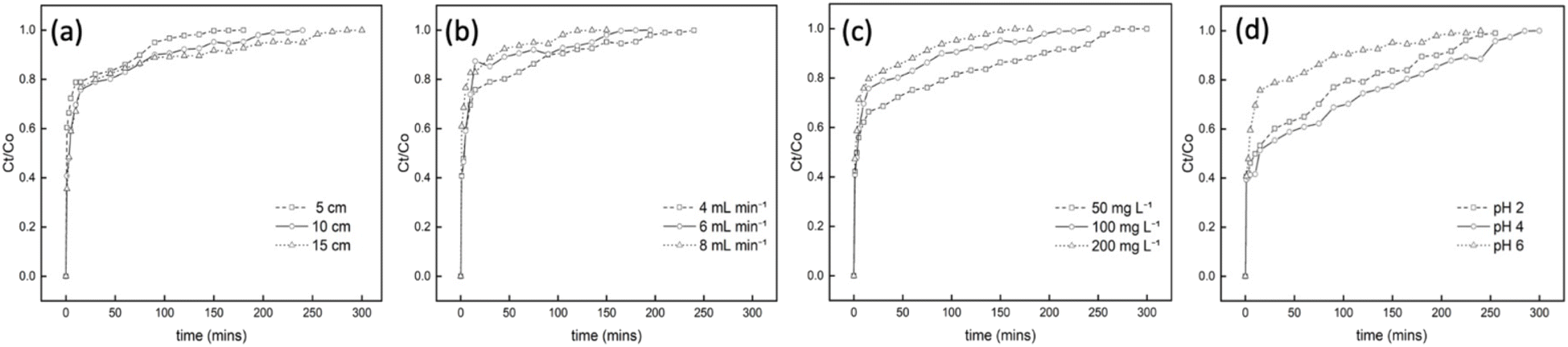 | ||
| Fig. 6 (a) Effect of bed height (flow rate 4 mL min−1, initial Cr6+ ions concentration 100 mg L−1), (b) effect of flow rate (bed height 10 cm, initial Cr6+ ions concentration 100 mg L−1) (c) effect of initial Cr6+ ions concentration (bed height 10 cm, flow rate 4 mL min−1), and (d) effect of pH level (bed height 10 cm, flow rate 4 mL min−1, initial Cr6+ ions concentration 100 mg L−1) on the breakthrough curves for the removal of Cr6+ ions from aqueous media. | ||
The impact of different flow rates in the breakthrough curves were indicated in Fig. 6(b). Results showed that when the flow rate is increased, breakthrough occurs much more rapidly, leading to a decreased breakthrough time. This is because the increased flow rate promotes Cr6+ ions to have lesser contact time with the PUAC, ultimately reducing the removal capacity of Cr6+ ions in the column.
Fig. 6(c) displays the inverse relationship between the initial concentration and breakthrough curve. As the initial Cr6+ ion concentration increases, saturation takes place faster, and the breakthrough time decreases. This is because the surface area readily available for adsorption is higher at lower initial concentrations and vice versa, resulting in lesser efficiency. This phenomenon occurs because an increase in the initial concentration acts as a driving force to overcome all the resistance to adsorption, resulting in an abrupt breakthrough.47
The effect of various pH levels in Cr6+ sequestration is shown in Fig. 6(d). It was revealed that the optimum breakthrough time (300 min) of the PUAC was observed at pH = 4. This observation might be attributed to the higher ratio of HCrO4− and Cr2O72− present in the adsorbate at pH = 4,21 which could significantly induce the uptake capacity of the PUAC. In contrast, the excessive protonation of the adsorbent surface at pH = 2 disrupted the interaction between Cr6+ and the adsorbent,1,44 leading to a decreased breakthrough time. Moreover, when pH was further increased from 4 to 6, there is an increased formation of CrO42− and Cr2O72− precipitates3,21 which cannot be adsorbed by the PUAC, resulting in a decrease in the breakthrough time from 300 to 240 min.
3.3 Breakthrough curve modeling
Breakthrough curves obtained under various conditions can be utilized to estimate the effectiveness of a column design. To adapt lab-scale column studies for industrial use, various mathematical models have been suggested. In this research, the Adams-Bohart, Thomas, and Yoon-Nelson models were employed to select the best-fit model for predicting the columns' dynamic behavior.| Parameter | kAB (L mg−1 min−1) | N0 (mg L−1) | R2 | |
|---|---|---|---|---|
| Bed height (cm) | 5 | 2.2 × 10⁻⁵ | 0.9151 | 0.816 |
| 10 | 2.4 × 10⁻⁵ | 0.6024 | 0.678 | |
| 15 | 1.8 × 10⁻⁵ | 0.5036 | 0.613 | |
| Flow rate (mL min−1) | 4 | 2.4 × 10⁻⁵ | 0.6024 | 0.678 |
| 6 | 2.9 × 10⁻⁵ | 0.7180 | 0.562 | |
| 8 | 2.3 × 10⁻⁵ | 0.7504 | 0.703 | |
| Initial metal concentration (mg L−1) | 50 | 4.0 × 10⁻⁵ | 0.4038 | 0.838 |
| 100 | 2.4 × 10⁻⁵ | 0.6024 | 0.678 | |
| 200 | 1.3 × 10⁻⁵ | 0.8981 | 0.696 | |
| pH | 2 | 3.1 × 10⁻⁵ | 0.7042 | 0.678 |
| 4 | 2.9 × 10⁻⁵ | 0.8279 | 0.895 | |
| 6 | 2.4 × 10⁻⁵ | 0.6024 | 0.678 |
The study found that the Adams-Bohart model can be used to predict the initial process of a continuous system, with high correlation coefficients obtained for the bed height and initial metal concentration breakthrough curves. However, the model's applicability decreased at higher parameters, indicating the need for an alternative approach to predict system behavior. Additionally, the observed decreasing trend in the rate constant, kAB, for all parameters suggests that external mass transfer dominates the system kinetics, which is influenced by flow conditions and contact surface area.48
| Parameter | kTh (L mg−1 min−1) | qTh (mg g−1) | R2 | |
|---|---|---|---|---|
| Bed height (cm) | 5 | 3.5 × 10⁻⁴ | 0.7107 | 0.935 |
| 10 | 2.1 × 10⁻⁴ | 0.3775 | 0.880 | |
| 15 | 1.7 × 10⁻⁴ | 0.3691 | 0.828 | |
| Flow rate (mL min−1) | 4 | 2.1 × 10⁻⁴ | 0.3775 | 0.880 |
| 6 | 3.1 × 10⁻⁴ | 0.3867 | 0.876 | |
| 8 | 4.3 × 10⁻⁴ | 0.9726 | 0.912 | |
| Initial metal concentration (mg L−1) | 50 | 3.5 × 10⁻⁴ | 0.2707 | 0.930 |
| 100 | 2.1 × 10⁻⁴ | 0.3775 | 0.880 | |
| 200 | 1.6 × 10⁻⁴ | 0.7357 | 0.866 | |
| pH | 2 | 1.5 × 10⁻⁴ | 0.8268 | 0.880 |
| 4 | 1.8 × 10⁻⁴ | 1.8026 | 0.978 | |
| 6 | 2.1 × 10⁻⁴ | 0.3775 | 0.880 |
| Parameter | kYN (min−1) | τcalc (min) | R2 | |
|---|---|---|---|---|
| Bed height (cm) | 5 | 3.5 × 10⁻² | 8.8843 | 0.935 |
| 10 | 2.1 × 10⁻² | 9.4383 | 0.880 | |
| 15 | 1.7 × 10⁻² | 13.842 | 0.828 | |
| Flow rate (mL min−1) | 4 | 2.1 × 10⁻² | 9.4383 | 0.880 |
| 6 | 3.1 × 10⁻² | 6.4446 | 0.876 | |
| 8 | 4.3 × 10⁻² | 5.8983 | 0.912 | |
| Initial metal concentration (mg L−1) | 50 | 1.7 × 10⁻² | 13.524 | 0.930 |
| 100 | 2.1 × 10⁻² | 9.4383 | 0.880 | |
| 200 | 3.2 × 10⁻² | 9.1966 | 0.866 | |
| pH | 2 | 1.5 × 10⁻² | 20.6707 | 0.880 |
| 4 | 1.7 × 10⁻² | 45.0640 | 0.978 | |
| 6 | 2.1 × 10⁻² | 9.4383 | 0.880 |
Table 4 presents the summary of the PUAC's performance for the sequestration of Cr6+ ions at various adsorption parameters. It can be observed that, the more favorable adsorption performance can be observed at higher bed heights, lower flow rates, and higher initial concentrations. Moreover, the adsorption performance of other adsorbents in similar conditions are summarized in Table 5. It has been found out that the PUAC's adsorption capacity is comparable to, or even performs better compared to other adsorbents found in the literature.
| Initial concentration (mg L−1) | Bed height (cm) | Flow rate (mL min−1) | pH | Total time (min) | Total mass adsorbed (mg) | Equilibrium uptake (mg g−1) | Effluent volume (mL) |
|---|---|---|---|---|---|---|---|
| 100 | 5 | 4 | 6 | 180 | 72 | 7.18 | 720 |
| 100 | 10 | 4 | 6 | 240 | 96 | 10.66 | 960 |
| 100 | 15 | 4 | 6 | 300 | 120 | 8.38 | 1200 |
| 100 | 10 | 4 | 6 | 240 | 96 | 10.66 | 960 |
| 100 | 10 | 6 | 6 | 195 | 117 | 10.56 | 1170 |
| 100 | 10 | 8 | 6 | 150 | 120 | 8.66 | 1200 |
| 50 | 10 | 4 | 6 | 300 | 60 | 9.48 | 1200 |
| 100 | 10 | 4 | 6 | 240 | 96 | 10.66 | 960 |
| 200 | 10 | 4 | 6 | 180 | 144 | 13.54 | 720 |
| 100 | 10 | 4 | 2 | 255 | 102 | 22.03 | 1020 |
| 100 | 10 | 4 | 4 | 300 | 120 | 28.41 | 1200 |
| 100 | 10 | 4 | 6 | 240 | 96 | 10.66 | 960 |
3.4 Regeneration studies
The adsorbent reusability is a crucial aspect in the lens of economic viability, especially in an industrial-scale setting. In the present study, the chromate-exhausted PUAC was subjected to desorption studies using a 0.1 M NaOH desorbing agent. The regeneration studies were performed by eluting the desorbing agent into the column at a flow rate of 2.5 mL min−1 for 30 min. The column was then rinsed with deionized water for another 30 min before employing another cycle for Cr6+ adsorption. After undergoing four (4) adsorption–desorption cycles, the removal efficiency of PUAC remained above 80% of its original removal capacity as shown in Fig. 7. This suggests that the composite material can be used repeatedly for the effective removal of Cr6+ ions from effluents.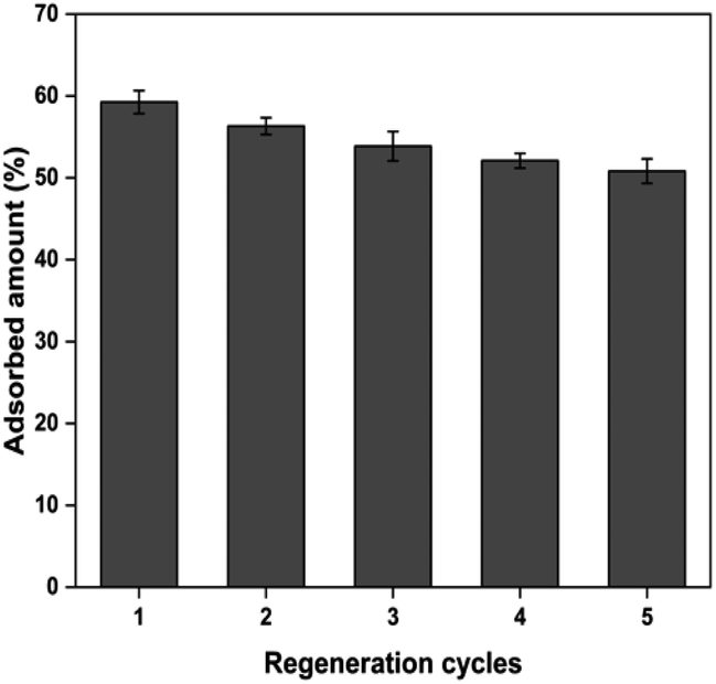 | ||
| Fig. 7 The reusability of polyurethane foam-activated carbon (PUAC) for the sequestration of Cr6+ ions. | ||
4 Conclusion
In conclusion, this study investigated the potential of utilizing both AC raw material and polyol in developing a PUAC composite made from coconut industry waste and by-products. This composite proved to be a highly effective adsorbent for removing Cr6+ ions from aqueous solutions, as demonstrated in fixed-bed column studies. The results showed that the adsorption capacity in a fixed-bed column set-up was dependent on flow rate and bed height, with higher flow rates resulting in decreased removal capacity and higher bed heights leading to improved removal capacity. Among the models applied to fit the experimental data, the Thomas and Yoon-Nelson models demonstrated a more suitable fitting to describe the breakthrough curves of adsorption processes under different fixed-bed conditions. Additionally, the study revealed that the PUAC can be reused even after four cycles without significantly affecting its adsorption capacity. Further, the successful synthesis of the adsorbent demonstrated the potential of PUAC for the removal of heavy metals in wastewater particularly Cr6+ ions in a larger scale.Conflicts of interest
The authors declare no conflicts of interest.Acknowledgements
The first author wishes to acknowledge the financial support received from the Philippine government's Department of Science and Technology (DOST), the NICER – Center for Sustainable Polymers of the Mindanao State University – Iligan Institute of Technology for providing the lab facility in the conduct of the study, Jaime Guihawan and Roger Jr Dingcong for their insights and invaluable feedback in writing the manuscript, the Philippine Japan Active Carbon for the provision of coco-shell-based activated carbon, and FABLAB Mindanao for making the fixed-bed column concept possible.References
- L. J. Martis, N. Parushuram and Y. Sangappa, Environ. Sci.: Adv., 2022, 1, 285–296 Search PubMed.
- S. Dutta and R. K. Sharma, Sep. Sci. Technol., 2019, 11, 371–416 CAS.
- S. Chen, Q. Yue, B. Gao, Q. Li, X. Xu and K. Fu, Bioresour. Technol., 2012, 113, 114–120 CrossRef CAS PubMed.
- I. Musbah, D. Cicéron, A. Saboni and S. Alexandrova, 2018.
- F. Parvin, S. Y. Rikta and S. M. Tareq, in Nanotechnology in Water and Wastewater Treatment, Elsevier, 2019, pp. 137–157 Search PubMed.
- R. Lakshmipathy and N. C. Sarada, Environ. Sci.: Water Res. Technol., 2015, 1, 244–250 RSC.
- M. Bhaumik, K. Setshedi, A. Maity and M. S. Onyango, Sep. Purif. Technol., 2013, 110, 11–19 CrossRef CAS.
- S. Srivastava, S. B. Agrawal and M. K. Mondal, Environ. Prog. Sustainable Energy, 2019, 38, S68–S76 CrossRef CAS.
- J. Kotaś and Z. Stasicka, Environ. Pollut., 2000, 107, 263–283 CrossRef PubMed.
- L. Mukosha, O. S. Maurice and A. Ochieng, Chem. Eng. Commun., 2020, 207, 1415–1425 CrossRef CAS.
- M. Sulyman, J. Namiesnik and A. Gierak, Pol. J. Environ. Stud., 2017, 26, 479–510 CrossRef CAS PubMed.
- S. S. Banerjee, M. V. Joshi and R. V. Jayaram, Sep. Sci. Technol., 2005, 39, 1611–1629 CrossRef.
- A. Bakshi and A. K. Panigrahi, Toxicol. Rep., 2018, 5, 440–447 CrossRef CAS PubMed.
- J. P. Beukes, S. P. du Preez, P. G. van Zyl, D. Paktunc, T. Fabritius, M. Päätalo and M. Cramer, J. Cleaner Prod., 2017, 165, 874–889 CrossRef CAS.
- V. Velma, S. S. Vutukuru and P. B. Tchounwou, Rev. Environ. Health, 2009, 24(2), 129–145 CAS.
- S. P. Tembhare, D. P. Barai, B. A. Bhanvase and M. Y. Salunkhe, in Handbook of Nanomaterials for Wastewater Treatment, Elsevier, 2021, pp. 575–603 Search PubMed.
- K. Salnikow and A. Zhitkovich, Chem. Res. Toxicol., 2008, 21, 28–44 Search PubMed.
- S. N. A. Abas, M. H. S. Ismail, L. Kamal and S. Izhar, 2013, 13.
- Y. Zhang and C. Banks, Environ. Technol., 2005, 26, 733–744 CrossRef CAS PubMed.
- Z. A. ALOthman, A. Y. Badjah and I. Ali, J. Mol. Liq., 2019, 275, 41–48 CrossRef CAS.
- S. Mandal, J. Calderon, S. B. Marpu, M. A. Omary and S. Q. Shi, J. Contam. Hydrol., 2021, 243, 103869 CrossRef CAS.
- E. E. Baldez, N. F. Robaina and R. J. Cassella, J. Hazard. Mater., 2008, 159, 580–586 CrossRef CAS PubMed.
- Y. Lu and R. C. Larock, Biomacromolecules, 2008, 9, 3332–3340 CrossRef CAS PubMed.
- W. He, P. Kang, Z. Fang, J. Hao, H. Wu, Y. Zhu and K. Guo, Ind. Eng. Chem. Res., 2020, 59, 17513–17519 CrossRef CAS.
- X. Leng, C. Li, X. Cai, Z. Yang, F. Zhang, Y. Liu, G. Yang, Q. Wang, G. Fang and X. Zhang, RSC Adv., 2022, 12, 13548–13556 RSC.
- A. Lubguban, R. Malaluan, A. Alguno, A. Tilendo and A. Maputi, Process for the Production of Polyester Polyols and Flexible Polyurethane Foam Derived from Coconut Oil, Philippine Pat., 12021050200, Intellectual Property of the Philippines, 2022 Search PubMed.
- Y.-C. Tu, P. Kiatsimkul, G. Suppes and F.-H. Hsieh, J. Appl. Polym. Sci., 2007, 105, 453–459 CrossRef CAS.
- A. Keshavarz, H. Zilouei, A. Abdolmaleki, A. Asadinezhad and A. A. Nikkhah, Int. J. Environ. Sci. Technol., 2016, 13, 699–710 CrossRef CAS.
- R. de A. Delucis, W. L. E. Magalhães, C. L. Petzhold and S. C. Amico, Polym. Compos., 2018, 39, E1770–E1777 CrossRef CAS.
- D.-M. Guo, Q.-D. An, Z.-Y. Xiao, S.-R. Zhai and Z. Shi, RSC Adv., 2017, 7, 54039–54052 RSC.
- G. S. Bohart and E. Q. Adams, J. Am. Chem. Soc., 1920, 42, 523–544 CrossRef.
- H. C. Thomas, J. Am. Chem. Soc., 1944, 66, 1664–1666 CrossRef CAS.
- D. T. Mekonnen, E. Alemayehu and B. Lennartz, Materials, 2021, 14, 5466 CrossRef CAS PubMed.
- Y. H. Yoon and J. H. Nelson, Am. Ind. Hyg. Assoc. J., 1984, 45, 509–516 CrossRef CAS PubMed.
- A. B. Albadarin, C. Mangwandi, A. H. Al-Muhtaseb, G. M. Walker, S. J. Allen and M. N. M. Ahmad, Chin. J. Chem. Eng., 2012, 20, 469–477 CrossRef CAS.
- M. Shoaib Suleman, S. Khan, T. Jamil, W. Aleem, M. Shafiq and N. Gull, Asian J. Appl. Sci., 2014, 2(5) Search PubMed.
- D. Wu, L. Fang, Y. Qin, W. Wu, C. Mao and H. Zhu, Mar. Pollut. Bull., 2014, 84, 263–267 CrossRef CAS.
- A. G. Shirke, P. Desai, M. Vashisht, B. Z. Dholakiya and K. Kuperkar, J. Surf. Sci. Technol., 2020, 125–135 CAS.
- H. Li, L. Liu and F. Yang, Mar. Pollut. Bull., 2012, 64, 1648–1653 CrossRef CAS PubMed.
- M. Iqhrammullah, Marlina, R. Hedwig, I. Karnadi, K. H. Kurniawan, N. G. Olaiya, M. K. Mohamad Haafiz, H. P. S. Abdul Khalil and S. N. Abdulmadjid, Polymers, 2020, 12, 903 CrossRef PubMed.
- S. J. Eichhorn and W. W. Sampson, J. R. Soc., Interface, 2010, 7, 641–649 CrossRef CAS PubMed.
- G. Nam, S. Choi, H. Byun, Y.-M. Rhym and S. E. Shim, Macromol. Res., 2013, 21, 958–964 CrossRef CAS.
- M. Udayakumar, B. El Mrabate, T. Koós, K. Szemmelveisz, F. Kristály, M. Leskó, Á. Filep, R. Géber, M. Schabikowski, P. Baumli, J. Lakatos, P. Tóth and Z. Németh, Arab. J. Chem., 2021, 14, 103214 CrossRef CAS.
- W. El Malti, M. Hamieh, A. Noaman, R. Nasser El-Dine, A. Hijazi and W. Al-Khatib, J. Ecol. Eng., 2021, 22, 99–110 CrossRef.
- R. G. Dingcong, R. M. Malaluan, A. C. Alguno, D. J. E. Estrada, A. A. Lubguban, E. P. Resurreccion, G. G. Dumancas, H. H. Al-Moameri and A. A. Lubguban, RSC Adv., 2023, 13, 1985–1994 RSC.
- S. H. Hasan, D. Ranjan and M. Talat, J. Hazard. Mater., 2010, 181, 1134–1142 CrossRef CAS.
- P. Kumar and M. S. Chauhan, J. Environ. Chem. Eng., 2019, 7, 103218 CrossRef CAS.
- N. Tandon, E. Cimetta, S. Bhumiratana, A. Godier-Furnemont, R. Maidhof and G. Vunjak-Novakovic, Biomater. Sci., 2013, 1178–1194 Search PubMed.
- S. Babel and T. A. Kurniawan, Chemosphere, 2004, 54, 951–967 CrossRef CAS PubMed.
- V. Vinodhini and N. Das, Am.–Eurasian J. Sci. Res., 2009, 4, 324 CAS.
- T. E. Abilio, B. C. Soares, J. C. José, P. A. Milani, G. Labuto and E. N. V. M. Carrilho, Environ. Sci. Pollut. Res., 2021, 28(19), 24816–24829 CrossRef CAS PubMed.
| This journal is © The Royal Society of Chemistry 2023 |