 Open Access Article
Sheet-on-sheet ZnIn2S4@RGO-modified separators with abundant sulfur vacancies for high-performance Li–S batteries†
Liping Wu‡
a,
Gang Liu‡a,
Hongyuan Xub,
Zhenwei Hua,
Tao Mei a,
Jingwen Qiana and
Xianbao Wang
 *a
*a
aHubei Collaborative Innovation Center for Advanced Organic Chemical Materials, Overseas, Expertise Introduction Center for Discipline Innovation (D18025), Key Laboratory for the Green Preparation and Application of Functional Materials, Hubei Key Laboratory of Polymer Materials, School of Materials Science and Engineering, Hubei University, Wuhan 430062, P. R. China. E-mail: wangxb68@aliyun.com; Fax: +86 27 8866 1729; Tel: +86 27 8866 2132
bSuzhou Academy, Xi'an Jiaotong University, Suzhou, Nano Science and Technology Institute, Suzhou Institute for Advanced Research, University of Science and Technology of China, Suzhou, Jiangsu 215123, China
First published on 9th May 2023
Abstract
A novel sheet-on-sheet architecture with abundant sulfur vacancies (Vs) is designed by in situ growth of flake-like ZnIn2S4 on the reduced graphene oxide (Vs-ZIS@RGO) surface, which serves as a functional layer on the separators for high-performance lithium-sulfur batteries (LSBs). Benefiting from the sheet-on-sheet architecture, the separators exhibit rapid ionic/electronic transfer, which is capable of supporting fast redox reactions. The vertically ordered ZnIn2S4 shortens the diffusion pathways of lithium-ions and the irregularly curved nanosheets expose more active sites to effectively anchor lithium polysulfides (LiPSs). More importantly, the introduction of Vs adjusts the surface or interface electronic structure of ZnIn2S4, enhancing the chemical affinity to LiPSs while accelerating conversion reaction kinetics of LiPSs. As expected, the batteries with Vs-ZIS@RGO modified separators exhibit an initial discharge capacity of 1067 mA h g−1 at 0.5C. Even at 1C, the excellent long cycle stability (710 mA h g−1 over 500 cycles) with an ultra-low decay rate of 0.055% per cycle is also attained. This work proposes a strategy of designing the sheet-on-sheet structure with rich sulfur vacancies, which provides a new perspective to rationally devise durable and efficient LSBs.
Introduction
Lithium-sulfur batteries (LSBs) are regarded as one of the most promising energy storage systems due to the high theoretical energy density and low cost of sulfur.1–3 However, the development of LSBs still faces three main challenges, namely, the volume change and the insulation of sulfur, and the shuttle effects caused by lithium polysulfides (LiPSs).4,5 In particular, the notorious “shuttle effects” and sluggish reaction kinetics lead to low sulfur utilization and fast capacity decay, which pose a great threat to the practical implementations.6,7To address such problems, a simple and effective method is to modify separators to minimize the shuttle effects of LiPSs.8–11 In recent years, plenty of metal sulfides such as ZnS,12 MoS2 (ref. 13 and 14) and In2S3 (ref. 15) have received extensive attention due to the exposing thiophilic sites that can strongly interact with LiPSs. Especially, ZnIn2S4, as a typical ternary metal sulfide semiconductor material, has been applied in LSBs due to its high chemical stability and remarkable catalytic activity.16,17 However, due to the microsphere morphology of pure ZnIn2S4, the electron–hole pairs would recombine rapidly, thus reducing the activity of ZnIn2S4. At present, most of the studies have found that the performance of ZnIn2S4 can be enhanced by the incorporation of RGO.18–21 The high electrical conductivity and tunable surface property of RGO are capable of simultaneously enhancing the interaction in nanocomposites and improving the electron-transfer efficiency.22–24 In addition, to effectively exert the catalytic activity of functional materials, recent research has shown that building sulfur vacancies (Vs) in metal sulfides is a feasible strategy. The introduced Vs is conducive to regulate the surface or interface electronic structure, thus improving the ability of rapid capture and catalytic conversion towards LiPSs.25–27 For instance, Rao's group prepared In2S3/RGO composites with rich sulfur vacancies, which promoted the catalytic conversion of intercepted LiPSs. The LSBs with In2S3−x/RGO offered a reversible capacity of 534 mA h g−1 after 450 cycles at 2C.15 Zhang et al. designed MoS2 nanosheets enriched with sulfur vacancies, which exhibited strong chemical affinity fast redox conversion to LiPSs. The batteries exhibited a high initial capacity of 945 mA h g−1 at 1C.28
Herein, a novel sheet-on-sheet architecture of ZnIn2S4@RGO composite with abundant sulfur vacancies (Vs-ZIS@RGO) was successfully designed and synthesized via a facile solvothermal and thermal treatment method. The sheet-on-sheet architecture was easily obtained by in situ growth of flake-like ZnIn2S4 on the reduced graphene oxide surface. And the abundant sulfur vacancies were achieved during the thermal treatment process, making it possible for enhancing the reactivity. Based on the sulfur vacancies design, the modified separators not only improved the chemical affinity to LiPSs, but also accelerated conversion reaction kinetics of LiPSs. Benefiting from the sheet-on-sheet architecture, the ionic/electronic transfer was enhanced, which was conducive to supporting fast redox reactions. In addition, the vertically ordered flake-like ZnIn2S4 provided a shorter transport path for lithium-ions and the irregularly curved ZnIn2S4 nanosheets exposed more active sites for effectively anchoring LiPSs. As expected, the batteries with Vs-ZIS@RGO modified separator exhibited an initial discharge capacity of 1067 mA h g−1 at 0.5C and stable cycling properties (710 mA h g−1 over 500 cycles at 1C) with a minor capacity decay of 0.055% per cycle.
Experimental section
Materials
ZnCl2 (98%, Macklin, China), InCl3·4H2O (99.99%, Macklin, China), C2H5NS (TAA, >98.0%, Macklin, China) and C3H8O3 (>99.5%, Macklin, China). Graphene oxide (GO, The Sixth Element, China). All the reagents are analytical grade and used without further purifications.Preparation of sheet-on-sheet structure of ZnIn2S4@RGO with abundant sulfur vacancies
Firstly, sheet-on-sheet structure of ZnIn2S4@RGO was prepared through a solvothermal method: 60 mg of GO were dispersed in 24 mL of distilled water (pH = 2.5) by ultrasonication for 1 h. Then, 81.60 mg of ZnCl2, 175.8 mg of InCl3·4H2O and 90 mg of TAA were mixed with 24 mL of GO aqueous dispersion with sonicating for 20 min. Next, 6 mL of C3H8O3 was added in the solution under vigorous magnetic stirring. The obtained solution was poured into a 50 mL autoclave to keep at 80 °C for 12 h. After cooling to room temperature naturally, the product was washed with absolute alcohol and distilled water several times and vacuum dried at 60 °C overnight.The pristine ZnIn2S4@RGO was modified by annealing at 600 °C for 1 h in a nitrogen flow at a ramping rate of 10 °C min−1 to induced sulfur vacancies in ZnIn2S4.
Preparation of modified separators
The Vs-ZIS@RGO (or ZIS@RGO or GO) was mixed with carbon black and polyvinylidene fluoride at the mass ratio of 8![[thin space (1/6-em)]](https://www.rsc.org/images/entities/char_2009.gif) :
:![[thin space (1/6-em)]](https://www.rsc.org/images/entities/char_2009.gif) 1
1![[thin space (1/6-em)]](https://www.rsc.org/images/entities/char_2009.gif) :
:![[thin space (1/6-em)]](https://www.rsc.org/images/entities/char_2009.gif) 1, respectively. Then, the N-methyl pyrrolidone was dropped into the mixture. Afterward, the uniformed slurry under the continuous ball milling process was coated on the surface of PP separator using a doctor blade with a coating thickness of 50 μm. Then the coated modified separators were dried at 45 °C overnight. Finally, the dry modified separators were cut into a circle and further to assemble the coin cell in an argon-filled glove box.
1, respectively. Then, the N-methyl pyrrolidone was dropped into the mixture. Afterward, the uniformed slurry under the continuous ball milling process was coated on the surface of PP separator using a doctor blade with a coating thickness of 50 μm. Then the coated modified separators were dried at 45 °C overnight. Finally, the dry modified separators were cut into a circle and further to assemble the coin cell in an argon-filled glove box.
Material characterization
The morphologies and structures of samples were measured via the scanning electron microscopy (SEM) and transmission electron microscopy (TEM). The elemental composition of samples was analyzed via the energy dispersive X-ray spectroscopy (EDS) mapping. X-ray diffraction (XRD) diffraction patterns of all samples were recorded on a Bruker D8 phaser with Cu Kα radiation (λ = 0.1542 nm). Surface functional groups were obtained by a Nicolet iS50 FTIR spectrometer over a wavenumber range from 4000 to 400 cm−1 (Thermo Fisher Scientific, USA). Raman spectra were collected by Witech CRM200 spectrometer with 532 nm excitation of Ar+ ion laser at room temperature. Electron paramagnetic resonance (EPR) measurement was analyzed by using an Endor spectrometer (BrukerA300). The chemical state and molecular structure were examined by a THERMO FISHERSICENTIFIC Escalab 250Xi high resolution X-ray photoelectron spectroscopy (XPS). The ultraviolet-visible-near-infrared (UV-vis-NIR) spectrometer attached to an integrating sphere (Shimadu UV-vis-NIR UV-3600 double beam spectrophotometer) was utilized to test the LiPS absorption state.Electrochemical measurements
The coin cells (CR2016) were assembled in the argon-filled glove box with the cathode consisted of elemental S, carbon black, and PVDF (7![[thin space (1/6-em)]](https://www.rsc.org/images/entities/char_2009.gif) :
:![[thin space (1/6-em)]](https://www.rsc.org/images/entities/char_2009.gif) 2
2![[thin space (1/6-em)]](https://www.rsc.org/images/entities/char_2009.gif) :
:![[thin space (1/6-em)]](https://www.rsc.org/images/entities/char_2009.gif) 1 ratio), the modified separators, the anode of lithium foils and the electrolyte composed of 1,3-dioxolane and 1,2-dimethoxymethane (v/v = 1
1 ratio), the modified separators, the anode of lithium foils and the electrolyte composed of 1,3-dioxolane and 1,2-dimethoxymethane (v/v = 1![[thin space (1/6-em)]](https://www.rsc.org/images/entities/char_2009.gif) :
:![[thin space (1/6-em)]](https://www.rsc.org/images/entities/char_2009.gif) 1) with 1 mol bis-(trifluoromethane) lithium sulfonamide (LiTFSI) and 1 wt% LiNO3. The electrolyte used for each cell was about 16.3 μL and the ratio of electrolyte/sulfur was 9 μL mg−1 under the sulfur loading of 1.6 mg cm−2. Cycling and rate performance tests were performed via Land battery test system in a voltage between 1.7 and 2.8 V (vs. Li+/Li). And the cyclic voltammetry (CV) was performed on the electrochemical workstation (Shanghai Chenhua Co. Ltd., chi 760e, China) at a scan rate of 0.1 mV s−1 under the same voltage range. The electrochemical impedance spectroscopy (EIS) was investigated in the frequency range of 100 kHz to 0.01 Hz. All the electrochemical measurements and assembly were conducted at room temperature.
1) with 1 mol bis-(trifluoromethane) lithium sulfonamide (LiTFSI) and 1 wt% LiNO3. The electrolyte used for each cell was about 16.3 μL and the ratio of electrolyte/sulfur was 9 μL mg−1 under the sulfur loading of 1.6 mg cm−2. Cycling and rate performance tests were performed via Land battery test system in a voltage between 1.7 and 2.8 V (vs. Li+/Li). And the cyclic voltammetry (CV) was performed on the electrochemical workstation (Shanghai Chenhua Co. Ltd., chi 760e, China) at a scan rate of 0.1 mV s−1 under the same voltage range. The electrochemical impedance spectroscopy (EIS) was investigated in the frequency range of 100 kHz to 0.01 Hz. All the electrochemical measurements and assembly were conducted at room temperature.
Polysulfide permeation measurements
The Li2S6 was chosen as a representative of the polysulfides. Li2S and sulfur (molar ratio of 1![[thin space (1/6-em)]](https://www.rsc.org/images/entities/char_2009.gif) :
:![[thin space (1/6-em)]](https://www.rsc.org/images/entities/char_2009.gif) 5) were dispersed in 1,3-dioxolane (DOL) and 1,2-dimethoxyethane (DME) (the corresponding volume ratio is 1
5) were dispersed in 1,3-dioxolane (DOL) and 1,2-dimethoxyethane (DME) (the corresponding volume ratio is 1![[thin space (1/6-em)]](https://www.rsc.org/images/entities/char_2009.gif) :
:![[thin space (1/6-em)]](https://www.rsc.org/images/entities/char_2009.gif) 1) solution. After vigorous stirring for 24 h at 80 °C, 0.1 M Li2S6 solution was prepared. Permeation measurements were performed using a H-shaped quartz tubes, which consisted of two identical glass containers and clamp-connected with an aperture of 15 mm in the middles. In a typical test, the separators were placed to fully cover the aperture, respectively. Then 25 mL of 10 mM Li2S6 solution was added into the left H-shape quartz tubes, and 25 mL of DME/DOL (v/v = 1
1) solution. After vigorous stirring for 24 h at 80 °C, 0.1 M Li2S6 solution was prepared. Permeation measurements were performed using a H-shaped quartz tubes, which consisted of two identical glass containers and clamp-connected with an aperture of 15 mm in the middles. In a typical test, the separators were placed to fully cover the aperture, respectively. Then 25 mL of 10 mM Li2S6 solution was added into the left H-shape quartz tubes, and 25 mL of DME/DOL (v/v = 1![[thin space (1/6-em)]](https://www.rsc.org/images/entities/char_2009.gif) :
:![[thin space (1/6-em)]](https://www.rsc.org/images/entities/char_2009.gif) 1) solution was added into the right. Lastly, the H-shaped quartz tubes was placed on a horizontal surface and observed for 24 h and recorded the process of color change via a mobile phone camera. The whole preparation of Li2S6 solution and permeation tests were carried out in an argon-filled glove box. The quantitative determinations of LiPSs flux through the separators were conducted by UV-vis test. And the permeate solutions on the right needed to be diluted for 10 times so that the acquired signals were in the reliable absorbance range of the UV-vis spectrophotometer.
1) solution was added into the right. Lastly, the H-shaped quartz tubes was placed on a horizontal surface and observed for 24 h and recorded the process of color change via a mobile phone camera. The whole preparation of Li2S6 solution and permeation tests were carried out in an argon-filled glove box. The quantitative determinations of LiPSs flux through the separators were conducted by UV-vis test. And the permeate solutions on the right needed to be diluted for 10 times so that the acquired signals were in the reliable absorbance range of the UV-vis spectrophotometer.
Computational method
The DFT calculations were performed by vienna ab initio simulation package (VASP). The generalized gradient approximation (GGA) of Perdew–Burke–Ernzerhof (PBE) was used to describe the exchange-correlation functional. The cut-off energy for the plane wave basis was set to 400 eV and a 2 × 2 × 1 Monkhorst–Pack mesh was employed. All the structures were fully relaxed (atomic position) up to 10−4 eV Å−1 force minimization and max force of 0.01 eV Å−1. Moreover, the binding energy (Eads) between the Li2S6 and substrate was calculated by the equation:| Eads = Etotal − ELi2S6 − Esub | (1) |
Results and discussion
Structural characterization of Vs-ZIS@RGO
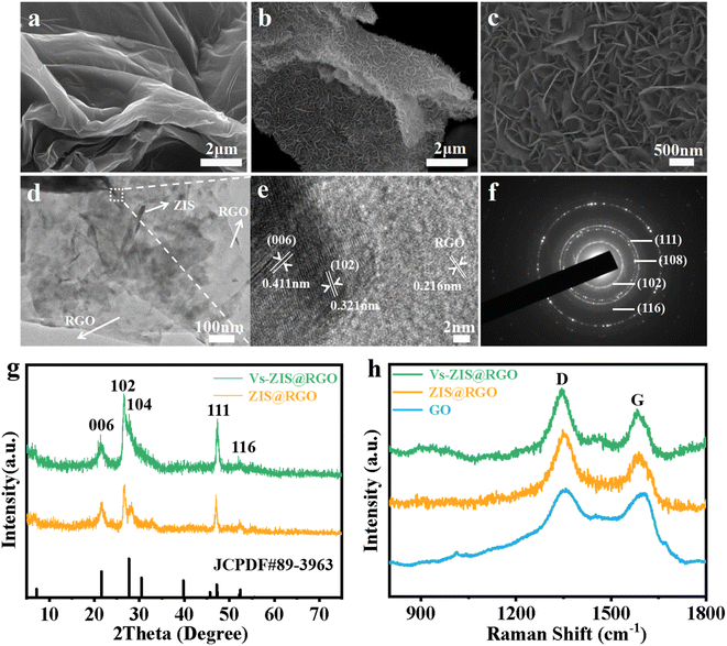
The schematic diagram of the synthesis process of sheet-on-sheet structure of ZIS@RGO with abundant sulfur vacancies was shown in Fig. 1. The ZIS@RGO was firstly prepared via a typical hydrothermal method and the pristine ZIS@RGO was subsequently modified by annealing at high temperature to induce sulfur vacancies. It could be clearly observed that the pure ZnIn2S4 was self-organized into a hierarchical peony-like microsphere (Fig. S1a†). With the introduction of GO, the ZIS nanosheets firstly in situ grew on the GO surface. Due to the large size in two dimensions of GO, the steric hindrance prevented further self-assembling process of ZIS nanosheets and finally a sheet-on-sheet structure of ZIS@RGO was formed (Fig. 2a and S1b). It should be noted that Vs-ZIS@RGO still maintained the morphology of stable sheet-on-sheet structure even at a high annealing temperature, which played an important role in improving the long cycle performance (Fig. 2b and c). The TEM image of Vs-ZIS@RGO was also depicted in Fig. 2d, further manifesting the sheet-on-sheet structure was successfully prepared. Meanwhile, the HRTEM image of Vs-ZIS@RGO in Fig. 2e exhibited the lattice spacings of 0.411 and 0.321 nm corresponding to the (006) and (102) crystal planes of ZIS and 0.216 nm assigned to RGO. In addition, the selected area electron diffraction (SAED) pattern (Fig. 2f) showed well-defined diffraction rings corresponding to (116), (111), (108) and (102) planes of Vs-ZIS@RGO, which was consistent with the following XRD analysis. According to the EDS elemental mapping images of Vs-ZIS@RGO in Fig. S2a–e,† Zn, In, S and C elements were uniformly distributed in Vs-ZIS@RGO. To comprehensively investigate the crystal structure, the XRD patterns of ZIS@RGO and Vs-ZIS@RGO were conducted (Fig. 2g). The clear diffraction peaks of ZIS@RGO were excellent assigned to the (006), (102), (104), (111), and (116) crystal planes of hexagonal phase of ZnIn2S4 (JCPDS 89-3963), respectively. And the XRD peaks of Vs-ZIS@RGO were similar to that of ZIS@RGO, indicating the crystal structure of Vs-ZIS@RGO was maintained after the thermal treatment. In addition, Raman spectroscopy was used to confirm the existence of RGO in the nanocomposite. As depicted in Fig. 2h, the characteristic peaks at 1346 and 1596 cm−1 corresponded to the D and G bands of GO, respectively. Obviously, the ratios of ID/IG in the ZIS@RGO and Vs-ZIS@RGO were much higher than that of the original GO, indicating a successful reduction of GO to RGO in the nanocomposites. Additionally, the enhanced D band in the ZIS@RGO suggested interaction between the metal nanoparticles and GO, which further verified the successful synthesis of ZIS@RGO.21,29To get direct evidence for defective structure of ZIS, EPR analysis was firstly executed. As displayed in Fig. 3a, a strong EPR signal with a g-value of 2.00 was observed in Vs-ZIS@RGO while almost no obvious sign was appeared in ZIS@RGO, illustrating that abundant Vs were induced successfully in ZIS after the annealing treatment in N2. To further analyze the surface chemical composition of the samples, the chemical states of S, In and Zn in ZIS@RGO and Vs-ZIS@RGO were analyzed using XPS measurements. As shown in Fig. 3b, the spectrum of S 2p of ZIS @RGO could be fitted to two peaks (at 162.4 and 163.7 eV), which were assigned to S 2p3/2 and S 2p1/2. After the annealing, the peaks of S 2p shifted negatively and the intensity of peaks was decreased as well. Likewise, this phenomenon was observed in the In 3d and Zn 2p spectra (Fig. 3c and d). The binding energies of In 3d5/2 and In 3d3/2 of ZIS@RGO were 445.5 and 453.1 eV, which were much higher than those of Vs-ZIS@RGO. The Zn 2p spectrum of ZIS@RGO at around 1022.6 eV and 1045.6 eV corresponded to Zn 2p3/2 and 2p1/2. Compared to ZIS@RGO, the two peaks are slightly shifted to lower binding energy in Vs-ZIS@RGO. All the XPS results fully demonstrated that the formation of Vs in ZIS@RGO after thermal treatment.15,30
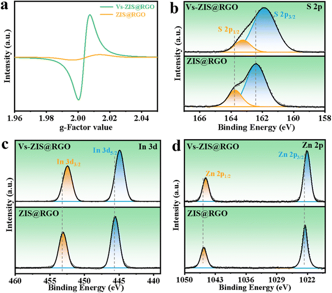 | ||
| Fig. 3 (a) EPR spectra of ZIS@RGO and Vs-ZIS@RGO at room temperature. XPS spectra of the (b) S 2p, (c) In 3d and (d) Zn 2p for ZIS@RGO and Vs-ZIS@RGO. | ||
Structural characterization of Vs-ZIS@RGO//PP
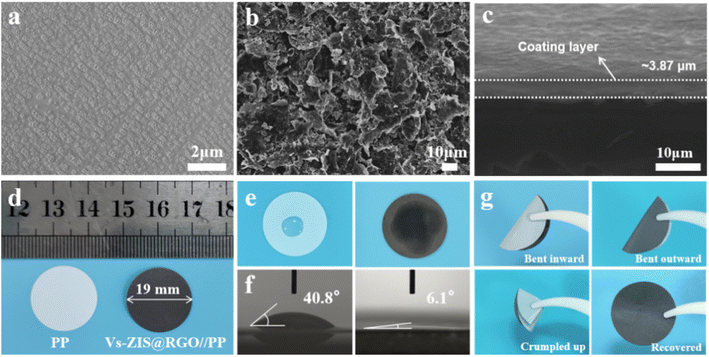
The SEM images of Vs-ZIS@RGO//PP and PP were depicted in Fig. 4a and b. Clearly, the Vs-ZIS@RGO were uniformly coated on the surface of the PP separator and covered the original pores of PP as well. The cross-sectional SEM image of Vs-ZIS@RGO//PP in Fig. 4c presented that the thickness of the Vs-ZIS@RGO layer was about 3.87 μm. As shown in Fig. S3,† the weight of Vs-ZIS@RGO//PP was slightly increased to 5.2 mg compared with PP (4.0 mg). In addition, the digital photos of PP and Vs-ZIS@RGO//PP were shown in Fig. 4d, the diameter of Vs-ZIS@RGO//PP was about 19 mm. And it can be clearly seen that the Vs-ZIS@RGO layer was smooth and flat. The wettability and the contact angle of Vs-ZIS@RGO//PP and PP with the electrolyte were tested in Fig. 4e and f. Notably, the Vs-ZIS@RGO//PP exhibited the better electrolyte affinity and the smaller contact angle of 6.1° compared with PP of 40.8°. Moreover, the Vs-ZIS@RGO//PP could be recovered by a bending process without Vs-ZIS@RGO exfoliation, further demonstrating its excellent mechanical toughness (Fig. 4g). These results fully demonstrated the superiority and potential of Vs-ZIS@RGO as a modified separator material for LSBs.Electrochemical characterization
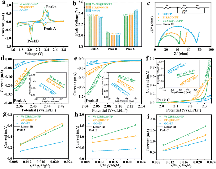
To demonstrate the excellent performance of Vs-ZIS@RGO//PP in LSBs, a series of electrochemical characterizations for different modified separators were tested. First, the different thickness of Vs-ZIS@RGO layer was measured to determine the optimum coating thickness. As shown in Fig. S6,† it could be clearly seen that the Vs-ZIS@RGO layer with 50 μm coating thickness (corresponding to 4 μm Vs-ZIS@RGO layer thickness) exhibited more excellent specific capacities and cyclic stability, indicating the 50 μm coating thickness was the most suitable thickness for Li–S battery compared with the two others. And the following electrochemical performance were performed with the 4 μm thickness of Vs-ZIS@RGO modified separators. The CV curves of cells with the modified separators were obtained (Fig. 5a). The two cathodic peaks were related to the transformation of S8 to Li2Sx (4 ≤ x ≤ 8) and finally to insoluble sulfur species (Li2S and Li2S2), and the anodic peak was related to the reversible transition from Li2S2/Li2S to S8. Notably, compared with GO//PP and ZIS@RGO//PP cells, the cathode/anode peaks of Vs-ZIS@RGO//PP cells exhibited a clear positive/negative shift and achieved the largest responding peak current. And the cells with Vs-ZIS@RGO//PP achieved the highest cathode potentials (2.343 and 2.041 V) and the lowest anode potential (2.349 V) compared to the others (Fig. 5b). The smallest polarization promoted the conversion of polysulfides, which were attributed to the introduction of abundant sulfur vacancies in ZIS@RGO. The EIS curves of the three modified separators were depicted in Fig. 5c. According to the fitted data, the Vs-ZIS@RGO//PP battery had the lowest charge transfer resistance (36.77 Ω), indicating that the abundant Vs enhanced the ionic/electronic transfer, which in turn improved the electrochemical performance. In addition, to precisely analyze the effect of Vs on enhancing electrochemical kinetics of LiPSs, the Tafel curves of the corresponding redox peaks were showed in Fig. 5d–f. Clearly, the Vs-ZIS@RGO//PP cells presented remarkably reduced Tafel slope values of both reduction and oxidation reactions, which further verified the best catalytic performance of Vs-ZIS@RGO//PP.31,32 The above results strongly confirmed that the formation of Vs played an essential role in elevating the redox kinetics for LSBs.Furthermore, the diffusion rate of lithium-ions, which could reflect the LiPSs diffusion to some extent, was studied by CV curves at different scan rates in Fig. S4a–c.† And the corresponding linear relationship between the square root of the scan rate and the cell peak current was investigated in Fig. 5g–i. Then, the diffusion coefficients of lithium-ions (DLi+) could be analyzed with Randles–Sevcik equation:33,34
| Ip = 2.69 × 10⁵n3/2SDLi+1/2CLi+ν1/2 | (2) |
In which Ip was the peak current, n referred to the number of charge transfer involved in the battery reaction (n = 2 in LSBs), S was the area of the electrode, DLi+ was the diffusion coefficient of lithium-ions (cm2 s−1), CLi+ stood for the lithium-ions concentration in the electrolyte (mol mL−1) and ν represented the scanning rate (V s−1). Since, the DLi+ values corresponded to the slope of the curve (Ip/ν1/2) in the case of constant value of n, S and CLi+. Apparently, the slopes of all fitted lines for the Vs-ZIS@RGO battery were higher than those for the other batteries, indicating the fastest lithium-ions diffusion. These results confirmed that Vs-ZIS@RGO//PP could effectively accelerate the redox reaction of LiPSs, thereby improving the utilization of sulfur.7,35 According to the CV curves at different scan rates, the peak voltage separations (between the Peak B and Peak C) of the Vs-ZIS@RGO//PP and ZIS@RGO//PP cells were depicted in Fig. S5.† It could be seen that the Vs-ZIS@RGO//PP cells displayed a smaller change in the peak voltage separations, indicating that Vs-ZIS@RGO reduced the voltage polarization and delivered a better polysulfide reaction kinetics.
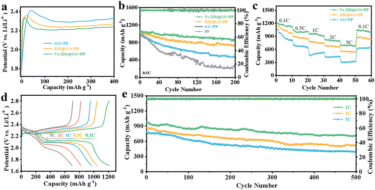
To evaluate the Li2S oxidation activation barrier, the charge voltage profiles of three cells were performed in Fig. 6a. The Vs-ZIS@RGO//PP cells presented the lowest potential barrier (2.34 V) compared to the ZIS@RGO//PP (2.36 V) and GO//PP (2.42 V). The lowest potential barrier of the Vs-ZIS@RGO material indicated an enhanced redox reaction rate, which was in agreement with the previous results obtained in Tafel curves.33,36 The cycling performance of cells with various separators was firstly measured to reveal the enhanced performance contributed by Vs. As showed in Fig. 6b, the initial discharge capacity of the Vs-ZIS@RGO//PP battery was close to the high value of 1067 mA h g−1 at 0.5C, and the high discharge capacity of 878 mA h g−1 was maintained after 200 cycles with a capacity retention rate of 82.3%. Whereas, the ZIS@RGO//PP, GO//PP and PP cells showed much lower capacity retention rates of 70.1%, 46.6%, and 30.4%, respectively. The rate capability of LSBs was performed at various current densities. As shown in Fig. 6c, the Vs-ZIS@RGO//PP cells exhibited excellent specific capacities of 1209, 1046, 960, 828 and 701 mA h g−1 at 0.1, 0.5, 1, 2 and 5C, respectively, which were higher than the other two batteries. When the rate was switched back to 0.1C, the discharge capacity remained at around 1047 mA h g−1, showing excellent responsiveness and rate performance. Such excellent rate performance and cycling stability of Vs-ZIS@RGO//PP cells further led us to conclude that the existence of Vs enhanced the chemisorption of LiPSs and accelerates the kinetics of LiPSs conversion. Meanwhile, the charge/discharge curves of the Vs-ZIS@RGO//PP battery at various current rates were showed in Fig. 6d. Notably, the Vs-ZIS@RGO//PP battery existed two distinct discharge plateaus at all different current rates, corresponding to two typical reduction stages. These plateaus are flat and stable, which suggested a kinetically efficient reaction process. Furthermore, the Vs-ZIS@RGO//PP cells were further tested at high current density for more than 500 cycles (Fig. 6e). It could be seen that the cells depicted high reversible capacities of 710, 522 and 401 mA h g−1 at 1, 2 and 5C, respectively. Even at 1C, the Vs-ZIS@RGO//PP battery showed a satisfactory 72.2% capacity retention with a minor capacity fade of 0.055% per cycle. Furthermore, the cycling performance of the Vs-ZIS@RGO//PP batteries under a higher sulfur loading was also investigated at 0.2C in Fig. S7.† When the sulfur loadings increased to 2.0 and 3.0 mg cm−2, the batteries with Vs-ZIS@RGO//PP still delivered a high reversible capacity of 774 and 587 mA h g−1 after 100 cycles with a capacity retention of 80.8 and 78.3%, respectively. These results fully indicated that the high electrochemical reversibility undeniably benefited from the Vs-ZIS@RGO layer that effective promoted the reuse of the trapped LiPSs.
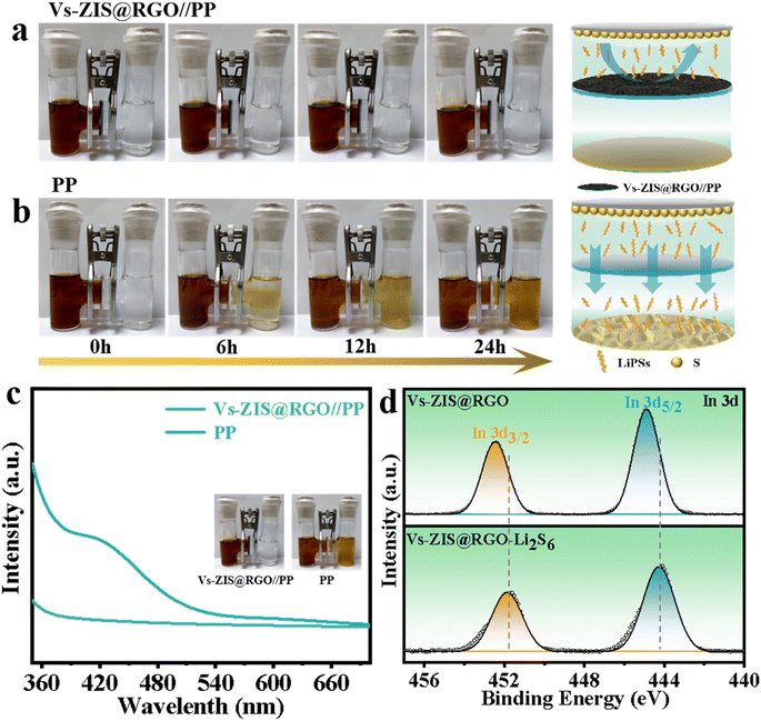
To intuitively evaluate the blocking effect of Vs-ZIS@RGO//PP on LiPSs, the permeation experiments using a visualized H-type glass device were designed in Fig. 7a and b. In the H-type device with the PP separator, the yellow-brown LiPSs gradually passed through PP from the left tube to the right tube with increasing time and reached a high level after 12 h, indicating that the PP hardly prevented the shuttle of LiPSs. In contrast, no obvious diffusion phenomenon of LiPSs was observed for Vs-ZIS@RGO//PP even after 24 h, demonstrating the superior ability for suppressing the LiPSs shuttle. Furthermore, after the permeation experiment, UV-vis was used to quantitatively determine the LiPSs flux (Fig. 7c). The noticeable characteristic absorption peaks of LiPSs were observed in the range of 400–450 nm for PP while no obvious LiPSs absorption peak for Vs-ZIS@RGO//PP appeared in the same range.37 Such a clear comparison indicated that Vs-ZIS@RGO//PP had better LiPSs adsorption capacity, which was beneficial to improve the rate and cycling performance of LSBs. In addition, the strong chemical interaction between ZnIn2S4 and LiPSs was further evaluated by XPS analysis after. As depicted in Fig. 7e and S8,† comparing to that of the pristine Vs-ZIS@RGO sample, the characteristic peaks of In 2p and Zn 2p spectra were shifted to lower binding energies after contacting with LiPSs, which were attributed to the electron transfer from LiPSs to In/Zn atoms. The negative shifts of In 2p and Zn 2p spectra demonstrated the strong chemical affinity towards LiPSs.38
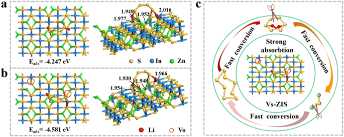
To further investigate the synergistic mechanism of immobilizing LiPSs at the molecular lever, the DFT calculations were performed in Fig. 8a and b. Obviously, the neighboring sulfur and metal atoms of Vs-ZIS moved toward the Vs to equilibrate the uneven electron cloud density on the surface (presented on the left).39 The generation of Vs increased the Vs-ZIS polarity, which was conducive to capturing LiPSs. The binding energy of Vs-ZIS to Li2S6 was as high as −4.581 eV, while the interaction energy of Li2S6 on ZIS (−4.247 eV) was relatively lower, implying that Vs-ZIS was more favorable for adsorbing Li2S6. And the bond lengths between Li2S6 and Vs-ZIS were shorter than that of ZIS, which further demonstrated that Vs were effective for the chemical fixation of LiPSs on ZIS (presented on the right).40–42 In addition, the bond lengths of Li–S and S–S bonding in Li2S6 on Vs-ZIS were much longer that on ZIS (Table S1†), indicating that Vs-ZIS could weaken the S–S bonding of Li2S6 and thus promoted the conversion of LiPSs.43,44 Moreover, the adsorption-catalysis mechanism of Vs-ZIS@RGO towards LiPSs was intuitively described in Fig. 8c. As a promising separator modification material for LSBs, Vs-ZIS@RGO could enhance chemical affinity to LiPSs while accelerate conversion reaction kinetics of LiPSs.
Meanwhile, the surface morphology of Li anode and separators after 200 cycles was measured to demonstrate the excellence of Vs-ZIS@RGO//PP. From the SEM image of Li anode (Fig. S9a†), it could be seen that the surface of the lithium anode in contact with PP was rough and showed a large number of cracks, indicating the severe formation of lithium dendrites. In contrast, Fig. S9b† presented the smooth surface of the Li anode in the Vs-ZIS@RGO//PP battery, confirming the powerful ability of Vs-ZIS@RGO//PP to effectively anchor LiPSs. Moreover, the morphological difference of the side facing the Li anode for the PP and Vs-ZIS@RGO//PP were systematically illustrated in Fig. S10a and b.† The pores of PP were covered with many blocky-shaped species, which were probably the deposits of insoluble sulfides (Li2S and Li2S2). And for the Vs-ZIS@RGO//PP, the pores still remained almost intact, ensuring the free migrating of lithium-ions. Additionally, the corresponding digital images were also showed (Fig. S11a and b†). The obvious yellow species were observed on the surface of PP compared to Vs-ZIS@RGO//PP, further illustrating the severe sulfides deposits on the PP surface. The results above further confirmed that Vs-ZIS@RGO could effectively trap LiPSs as well as promote LiPSs conversion, thus enhancing the electrochemical properties of LSBs.
Conclusions
In summary, a novel sheet-on-sheet architecture with abundant sulfur vacancies was designed by in situ growth of flake-like ZnIn2S4 on the RGO surface. Benefiting from the abundant Vs achieved in the thermal treatment process, the modified separators not only improved the chemical affinity to LiPSs, but also accelerated conversion reaction kinetics of LiPSs. And due to the sheet-on-sheet architecture, the ionic/electronic transfer was enhanced, which was conducive to supporting fast redox reactions. In addition, the vertically ordered flake-like ZnIn2S4 provided a shorter transport path for lithium-ions and the irregularly curved ZnIn2S4 nanosheets exposed more active sites for effectively anchoring LiPSs. Consequently, the batteries with Vs-ZIS@RGO modified separator showed a high initial discharge capacity of 1067 at 0.5C and outstanding long cycle stability with a minor capacity decay of 0.055% each cycle at 1C. Overall, this work proposes a strategy of designing the sheet-on-sheet structure with rich sulfur vacancies, which provides a new perspective to rationally devise durable and efficient LSBs.Author contributions
Liping Wu and Gang Liu contributed equally to this study: data curation, writing-original draft preparation, conceptualization, methodology, software. Hongyuan Xu: data curation, resources. Zhenwei Hu: writing – review & editing, supervision. Jingwen Qian: software, conceptualization. Tao Mei: funding acquisition, supervision, writing-review & editing. Xianbao Wang: project administration, funding acquisition, writing-review & editing.Conflicts of interest
There are no conflicts to declare.Acknowledgements
The work is financially supported by the National Natural Science Foundation of China (No. 52176185) and the Hubei Provincial Department of Education (grant no. D20201007). The authors also acknowledge Zihe Chen for assistance with the experiments and valuable discussion.References
- Z. Chen, Z. Zhang, C. Liu, C. Jiang, T. Mei, X. Wang and Y. Qian, J. Mater. Chem. A, 2020, 8, 1010–1051 RSC.
- Q. Wu, Z. Shadike, J. Xu, F. Cao and C. Li, Energy Storage Mater., 2023, 55, 73–83 CrossRef.
- R. Li, H. Peng, Q. Wu, X. Zhou, J. He, H. Shen, M. Yang and C. Li, Angew. Chem., Int. Ed., 2020, 59, 12129–12138 CrossRef CAS PubMed.
- R. Li, J. He, M. Lei, M. Yang and C. Li, Chem. Eng. J., 2022, 446, 137294 CrossRef CAS.
- Q. Wu, X. Zhou, J. Xu, F. Cao and C. Li, ACS Nano, 2019, 13, 9520–9532 CrossRef CAS PubMed.
- X. Zhou, J. Tian, Q. Wu, J. Hu and C. Li, Energy Storage Mater., 2020, 24, 644–654 CrossRef.
- S. Zhang, M. Liu, F. Ma, F. Ye, H. Li, X. Zhang, Y. Hou, Y. Qiu, W. Li, J. Wang, J. Wang and Y. Zhang, J. Mater. Chem. A, 2015, 3, 18913–18919 RSC.
- Y. Wang, L. Zhu, J. Wang, Z. Zhang, J. Yu and Z. Yang, Chem. Eng. J., 2022, 433, 133792 CrossRef CAS.
- L. Li, H. Tu, J. Wang, M. Wang, W. Li, X. Li, F. Ye, Q. Guan, F. Zhu, Y. Zhang, Y. Hu, C. Yan, H. Lin and M. Liu, Adv. Funct. Mater., 2023, 33, 2212499 CrossRef.
- W. Liu, M. Lei, X. Zhou and C. Li, Energy Storage Mater., 2023, 58, 74–84 CrossRef.
- W. Yao, C. Tian, C. Yang, J. Xu, Y. Meng, I. Manke, N. Chen, Z. Wu, L. Zhan, Y. Wang and R. Chen, Adv. Mater., 2022, 34, e2106370 CrossRef PubMed.
- Z. Li, F. Zhang, L. Tang, Y. Tao, H. Chen, X. Pu, Q. Xu, H. Liu, Y. Wang and Y. Xia, Chem. Eng. J., 2020, 390, 124653 CrossRef CAS.
- Q. Wu, Z. Yao, X. Zhou, J. Xu, F. Cao and C. Li, ACS Nano, 2020, 14, 3365–3377 CrossRef CAS PubMed.
- M. Liu, C. Zhang, J. Su, X. Chen, T. Ma, T. Huang and A. Yu, ACS Appl. Mater. Interfaces, 2019, 11, 20788–20795 CrossRef CAS PubMed.
- D. He, J. Liu, b. Zhang, M. Wang, C. Liu, Y. Huo and Z. Rao, Chem. Eng. J., 2022, 427, 131711 CrossRef CAS.
- T. Meng, J. Gao, J. Zhu, N. Li, M. Xu, C. M. Li and J. Jiang, J. Mater. Chem. A, 2020, 8, 11976–11985 RSC.
- Z. Zhang, G. Luo, S. Zhou, W. Zeng, T. Mei, Z. Chen, X. Yu, X. Xiao and X. Wang, ACS Appl. Mater. Interfaces, 2021, 13, 14169–14180 CrossRef CAS PubMed.
- F. Tian, R. Zhu, J. Zhong, P. Wang, F. Ouyang and G. Cao, Int. J. Hydrogen Energy, 2016, 41, 20156–20171 CrossRef CAS.
- Y. Xia, Q. Li, K. Lv, D. Tang and M. Li, Appl. Catal. B Environ., 2017, 206, 344–352 CrossRef CAS.
- T. Yu, W. Wu, L. Liu, C. Gao and T. Yang, Ceram. Int., 2020, 46, 9567–9574 CrossRef CAS.
- L. Ye, J. Fu, Z. Xu, R. Yuan and Z. Li, ACS Appl. Mater. Interfaces, 2014, 6, 3483–3490 CrossRef CAS PubMed.
- L. Bai, Y. Xu, A. Liu, L. Dong, K. Zhang, W.-S. Li and F.-G. Zhao, Chem. Eng. J., 2022, 434, 134639 CrossRef CAS.
- Z. Liu, Y. Yang, Y. Yuan, L. Wang, J. Sheng and W. Fei, J. Mater. Chem. A, 2022, 10, 10427–10438 RSC.
- A. Paul, S. Ghosh, H. Kolya, C.-W. Kang, N. Chandra Murmu and T. Kuila, Chem. Eng. J., 2022, 443, 136453 CrossRef CAS.
- W. Gao, Q. Jin, Y. Liu, Y. Zhang, X. Wang and Z. Bakenov, Mater. Des., 2021, 210, 110060 CrossRef CAS.
- H.-J. Li, Y.-H. Song, K. Xi, W. Wang, S. Liu, G.-R. Li and X.-P. Gao, J. Mater. Chem. A, 2021, 9, 10704–10713 RSC.
- W. Liu, C. Luo, S. Zhang, B. Zhang, J. Ma, X. Wang, W. Liu, Z. Li, Q. H. Yang and W. Lv, ACS Nano, 2021, 15, 7491–7499 CrossRef CAS PubMed.
- H.-E. Wang, X. Li, N. Qin, X. Zhao, H. Cheng, G. Cao and W. Zhang, J. Mater. Chem. A, 2019, 7, 12068–12074 RSC.
- S. K. Movahed, M. Dabiri and A. Bazgir, Appl. Catal. Gen., 2014, 481, 79–88 CrossRef CAS.
- C. Du, Q. Zhang, Z. Lin, B. Yan, C. Xia and G. Yang, Appl. Catal. B Environ., 2019, 248, 193–201 CrossRef CAS.
- S. Li, J. Lin, Y. Ding, P. Xu, X. Guo, W. Xiong, D. Y. Wu, Q. Dong, J. Chen and L. Zhang, ACS Nano, 2021, 15, 13803–13813 CrossRef CAS PubMed.
- Z. Shi, Z. Sun, J. Cai, X. Yang, C. Wei, M. Wang, Y. Ding and J. Sun, Adv. Mater., 2021, 33, e2103050 CrossRef PubMed.
- M. Wang, L. Fan, Y. Qiu, D. Chen, X. Wu, C. Zhao, J. Cheng, Y. Wang, N. Zhang and K. Sun, J. Mater. Chem. A, 2018, 6, 11694–11699 RSC.
- Y. Cao, C. Liu, M. Wang, H. Yang, S. Liu, H. Wang, Z. Yang, F. Pan, Z. Jiang and J. Sun, Energy Storage Mater., 2020, 29, 207–215 CrossRef.
- G. Liu, Q. Zeng, Z. Fan, S. Tian, X. Li, X. Lv, W. Zhang, K. Tao, E. Xie and Z. Zhang, Chem. Eng. J., 2022, 448, 137683 CrossRef CAS.
- J. Pu, M. Han, T. Wang, X. Zhu, M. Lu, J. Chen, W. Liu, Y. Dai and Y. Tan, Electrochim. Acta, 2022, 404, 139597 CrossRef CAS.
- Z. Cheng, Y. Chen, Y. Yang, L. Zhang, H. Pan, X. Fan, S. Xiang and Z. Zhang, Adv. Energy Mater., 2021, 11, 2003718 CrossRef CAS.
- Z. Ye, Y. Jiang, L. Li, F. Wu and R. Chen, Adv. Mater., 2022, e2109552, DOI:10.1002/adma.202109552.
- Z. Li, C. Zhou, J. Hua, X. Hong, C. Sun, H. W. Li, X. Xu and L. Mai, Adv. Mater., 2020, 32, e1907444 CrossRef PubMed.
- J. Wu, Q. Ma, C. Lian, Y. Yuan and D. Long, Chem. Eng. J., 2019, 370, 556–564 CrossRef CAS.
- J. Qian, Y. Xing, Y. Yang, Y. Li, K. Yu, W. Li, T. Zhao, Y. Ye, L. Li, F. Wu and R. Chen, Adv. Mater., 2021, 33, e2100810 CrossRef PubMed.
- H. Zhang, L. Yang, P. Zhang, C. Lu, D. Sha, B. Yan, W. He, M. Zhou, W. Zhang, L. Pan and Z. Sun, Adv. Mater., 2021, 33, e2008447 CrossRef PubMed.
- Z. Shi, M. Li, J. Sun and Z. Chen, Adv. Energy Mater., 2021, 11, 2100332 CrossRef CAS.
- K. Zou, X. Chen, W. Jing, X. Dai, P. Wang, Y. Liu, R. Qiao, M. Shi, Y. Chen, J. Sun and Y. Liu, Energy Storage Mater., 2022, 48, 133–144 CrossRef.
Footnotes |
| † Electronic supplementary information (ESI) available. See DOI: https://doi.org/10.1039/d3ra02180g |
| ‡ Wu L. and Liu G. contributed equally to this work. |
| This journal is © The Royal Society of Chemistry 2023 |


