
 Open Access Article
 This Open Access Article is licensed under a Creative Commons Attribution-Non Commercial 3.0 Unported Licence
Pd-doped HKUST-1 MOFs for enhanced hydrogen storage: effect of hydrogen spillover†
Xiaoyu Huab,
Jinchuan Wangc,
Shangkun Lid,
Xuanhao Hue,
Rongxing Yec,
Linsen Zhouc,
Peilong Li *c and
Changlun Chen*a
*c and
Changlun Chen*a
aInstitute of Plasma Physics, HFIPS, Chinese Academy of Sciences, Hefei 230031, PR China. E-mail: clchen@ipp.ac.cn
bUniversity of Science and Technology of China, Hefei 230026, PR China
cInstitute of Materials, China Academy of Engineering Physics, Mianyang 621907, PR China. E-mail: dtscichina@126.com
dSchool of Electrical Engineering, Southwest Jiaotong University, Chengdu 611756, China
eSchool of Physical Science and Technology, Xinjiang University, Urumqi 830046, China
First published on 16th May 2023
Abstract
Extensive research has been devoted to developing metal nanoparticle (NP) doped porous materials with large hydrogen storage capacity and high hydrogen release pressure at ambient temperature. The ultra-sound assisted double-solvent approach (DSA) was applied for sample synthesis. In this study, tiny Pd NPs are confined into the pore space of HKUST-1, affording Pd@HKUST-1-DS with minimizing the aggregation of Pd NPs and subsequently the formation of Pd NPs on the external surface of HKUST-1. The experimental data reveal that the obtained Pd NP doped Pd@HKUST-1-DS possessed an outstanding hydrogen storage capacity of 3.68 wt% (and 1.63 wt%) at 77 K and 0.2 MPa H2 (and 298 K and 18 MPa H2), in comparison with pristine HKUST-1 and impregnated Pd/HKUST-1-IM. It is found that the storage capacity variation is not only ascribed to the different textural properties of materials but is also illustrated by the hydrogen spillover induced by different electron transport from Pd to the pores of MOFs (Pd@HKUST-1-DS > Pd/HKUST-1-IM), based on X-ray photoelectron spectroscopy and temperature desorption spectra. Pd@HKUST-1-DS, featuring high specific surface area, uniform Pd NP dispersion and strong interaction of Pd with hydrogen in the confined pore spaces of the support, displays the high hydrogen storage capacity. This work highlights the influence of spillover caused by Pd electron transport on the hydrogen storage capacity of metal NPs/MOFs, which is governed by both physical and chemical adsorption.
1. Introduction
The dramatic rise in the global mean concentration of atmospheric carbon dioxide caused by burning fossil fuels (such as coal and oil), from about 278 ppm in 1958 to 415.59 ppm in 2022, has given rise to a series of global natural disasters including climate anomalies,1 sea-level rise,2 global warming and sandy desertification.3 This makes it urgent to push the implementation of a cleaner fuel to replace the conventional fossil ones. Hydrogen is an important industrial gas in many industrial processes (such as metallurgical engineering,4 and semiconductor5) and also represents a cleaner and cheaper energy carrier because of its high gravimetric energy density, universal abundance and pollution-free nature.6 Despite its massive advantages, the widespread application of hydrogen as a transportation fuel in fuel cell electric vehicles (FCEVs) has been hindered by the lack of safe suitable hydrogen storage systems. Current hydrogen storage technologies on the industrial plant scale are compressed gas in pressurized tanks and liquefied hydrogen in cryogenic tanks,7 which are costly and low-mobility with large tank size in daily life. In this context, physisorption and chemisorption on solid materials has been a research focus because of its great potential to develop an advanced solid material-based hydrogen storage system with high security and economy.The achievement of efficient solid adsorption materials is critical to the success of hydrogen storage technology. Recently, a number of solid adsorbents, including activated carbon,8–10 zeolites,11 metal hydrides (e.g., LaNi5H6 and Mg2NiH4),12,13 complex metal hydrides (e.g., NaAlH4 and LiBH4)14 and metal–organic frameworks (MOFs),15,16 have been explored for hydrogen storage via physisorption and chemisorption. Among them, MOFs, a new class of functional porous materials, have attracted increasing attention for hydrogen storage due to their tunable chemical space, powerful surface functionality, large specific surface area (SSA) and strong polar metal sites. In 2004, Ni2(bipy)3(NO3)4 and Ni3(btc)2(3-pic)6(pd)3 were firstly applied in hydrogen adsorption, which exhibits high capacity at 77 K in comparison with the carbon.17 Subsequently, a variety of pristine MOFs (such as ZIF-8,18 MOF-200, MOF-210,19 NU-100, IRMOF-20,20 UIO-66,21 SNU-200,22 NaNi3(OH)(SIP)2,23 DUT-4,24 etc.) have been exploited as hydrogen storage adsorbents at 77 K. The hydrogen storage capacity can be further improved through introducing appropriate numbers of “guest” metal ions (Co2+, Cu2+, Fe2+, Zn2+, Li+, Na+, and K+)25–27 and organic ligands28,29 into MOFs, which is proposed due to the increasing unsaturated metal sites, modifiable electrostatic field or adjustable surface area and pore volume of the MOFs. Furthermore, Pd NPs can effectively enhance the operation temperature of materials' hydrogen storage and hydrogen uptake due to hydrogen spillover and formation of Pd hydride, which will reduce the cost of industrial hydrogen storage.30–32 Pd NPs were considered to be one of the most effective catalysts for hydrogen spillover, and bring high hydrogen uptake at low pressure in comparison with other transition metals. Hydrogen spillover induced by Pd NPs consists of a dissociative chemisorption of hydrogen molecules over the metallic surface, followed by migration of hydrogen atoms to the surface of the support. However, small metal NPs are prone to aggregate during the hydrogen adsorption process due to their high surface energy, and their activity is seriously influenced by their dispersion, size and shape and the support's textural property. To address the above issues, Martos's et al. optimized the reduction method and employed electroless platting reaction to prepare Pd/ZIF-8 with homogeneously dispersed Pd NPs, resulting in high adsorption capacity.33 The Pt/UIO-66-NH2 with the amino group-anchored Pt NPs possesses evenly distributed nanoscale Pt particles under a high Pt loading, exhibiting improved hydrogen storage through the spillover effect.32 Although those studies have illustrated that many porous materials with homogeneously dispersed Pd NPs can improve hydrogen storage capacity at room temperature due to domination of the hydrogen spillover effect, the current limited investigations are almost related to the microstructure of Pd NPs on the support, and the influence of the microenvironment around metal NPs via pore wall engineering of the porous hosts remains largely unclear for hydrogen storage.
In this work, an ultra-sound assisted double-solvent approach (DSA) was used to construct the Pd precursor into the pores of HKUST-1. The reduced Pd@HKUST-1-DS possesses interior pore-confined Pd NPs, which remarkably minimizes the aggregation of Pd NPs and subsequently generates Pd NPs on the external surface of HKUST-1. The highly dispersive Pd NPs inside the pores of Pd@HKUST-1-DS without blocking pores exhibit distinctly enhanced hydrogen storage capacity at 77 and 298 K, in which Pd@HKUST-1-DS possesses the highest hydrogen uptake, followed by impregnated Pd/HKUST-1-IM and pristine HKUST-1. Importantly, the hydrogen uptake of Pd@HKUST-1-DS is around 1.43 times higher than that of Pd/HKUST-1-IM at 298 K and 18 MPa. The distinct hydrogen storage capacity is not only attributed to the different textural properties of materials, but also to the hydrogen spillover induced by different electron transfer from Pd to the pores of MOFs. The corresponding results can deepen the understanding of the co-dominated hydrogen storage capacity of physisorption and chemisorption in metal NP/MOF-based hydrogen storage systems.
2. Experimental section
2.1. Materials
All reagents and solvents received were used without further purification. Copper(II) nitrate trihydrate (Cu(NO3)2·3H2O, AR, 99.0%), benzene-1,3,5-tricarboxylic acid (BTC, AR, 98.0%), N,N-dimethylformamide (DMF, C3H7NO, 99.8%), alcohol (CH3CH2OH, AR, 75.0%), potassium tetrachloropalladate (K2PdCl4, 32.6%), and n-hexane (C6H14, AR, 97%) were purchased from Aladdin Chemical Reagent Co. Ltd. (Shanghai, China).2.2. Synthesis of HKUST-1
HKUST-1 was synthesized using the hydrothermal method.34 Specifically, BTC (2.12 g, 10 mmol) was dissolved in a mixture of DMF (15 mL) and alcohol (15 mL), and the above mixture was dropwise added in the solution of Cu(NO3)2·3H2O (2.42 g, 10 mmol) in ultrapure water (30 mL) and was stirred for 10 min at room temperature. The homogeneous mixture was placed in a 100 mL Teflon-lined stainless-steel autoclave and heated at 393 K for 12 h. The blue product was collected by filtration, and washed thoroughly with fresh alcohol over three times, followed by solvent exchange with chloroform solution over four times for 2 days. The activated HKUST-1 was obtained by vacuum activation of the product at 393 K for an additional 16 h.2.3. Synthesis of 2.0 wt% Pd/HKUST-1-IM
Pd-loaded HKUST-1 (Pd/HKUST-1-IM) was prepared by the impregnation–reduction method. Activated HKUST-1 (0.6 g) was ultrasonically dispersed in alcohol (50 mL) for 2 h at room temperature. Then, the mixture of K2PdCl4 (12.25 mg, 0.0375 mmol) and DMF (10 mL) was dropwise added in the mixture of HKUST-1 and was stirred at room temperature for 24 h. The homogeneous mixture was dried at 333 K for 1 h using a vacuum rotary evaporator, subsequently further dried at 353 K for 12 h, and then reduced at 453 K for 1 h in H2/Ar (10/90, v/v). Finally, the Pd/HKUST-1-IM catalyst was prepared.2.4. Synthesis of 2.0 wt% Pd@HKUST-1-DS
The Pd(II) precursor was incorporated into HKUST-1 by adopting a double-solvent (DS) method, where n-hexane and water were used as hydrophobic and hydrophilic solvents, respectively. The relationship of pore volume (VK2PdCl4 < VHKUST-1) can result in it being adsorbed into the internal pores of HKUST-1. Typically, activated HKUST-1 (0.1 g) was ultrasonically dispersed in n-hexane for 2 h to achieve a homogeneous dispersion. Aqueous K2PdCl4 solution (6.2602 mg of K2PdCl4 in 80 μL of ultrapure water) was added dropwise to the above solution with constant sonication for 2 h, and then was stirred for another 2 h at room temperature. The solid was isolated by subsidence and filtration. The obtained materials were dried under vacuum at 373 K for 12 h and reduced at 453 K for 1 h in H2/Ar (10/90, v/v) to afford Pd@HKUST-1-DS.2.5. Hydrogen adsorption experiments
The hydrogen adsorption isotherms at 77 K were measured by using the volumetric method on a SETARAM PCT-PRO gas adsorption analyzer. In each adsorption measurement, approximately 0.1 g of sample was pretreated at 423 K under high vacuum for at least 12 h. The free-space calibration was performed by using ultrahigh purity helium gas and was evaluated 4 times. The pure H2 adsorption measurement was performed at 77 K up to 2 bar. All used pure gases were of high purity (99.999%).The hydrogen adsorption isotherms at 298 K were recorded using the gravimetric tank (GT) method on a high-pressure balanced suspension system. The dead volume and mass of the sample tube (and sample) were experimentally determined to use ultrahigh purity nitrogen gas (and ultrahigh purity helium gas) and were evaluated in the range of 0–20 MPa to obtain corrected data. N2 and H2 densities at different pressures were performed by using NIST Chemistry WebBook. In each adsorption measurement, the activated sample (about 0.5 g) was put into a stainless-steel reactor and was pretreated at 423 K under high vacuum for at least 12 h. The pure H2 adsorption measurement was performed at 298 K up to 20 MPa. The mass of the sample at different pressures was calculated using the following equation:
| mr = ms* − ρH × (Vt + Vs) + mt | (1) |
The uptake measurements were expressed in wt%, which is the ratio of the mass of gas absorbed minus the initial mass of the sample to the initial mass of the sample, and was evaluated using the following equation:
 | (2) |
2.6. Thermal desorption spectroscopy (TDS) experiments
TDS experiments were conducted in a home-made installation with helium refrigerant, quadrupole mass spectrometer and cryogenic reactor, which enables heating the sample from 20 to 773 K in the heating rate range of 0–10 K min−1. For low temperature TDS, a small amount of activated sample (about 5 mg) was outgassed under high vacuum at 423 K for at least 12 h. Then, the sample was cooled down to 77 K, and a certain pure H2 was added in a chamber for 10 min. The chamber was evacuated for 2 min using a turbomolecular pump to remove the non-adsorbed gas, and then the sample was promptly cooled down to 20 K. Quadrupole mass spectrometry was performed to record the desorption during heating materials from 20 to 200 K at a stable heating rate of 6 K min−1. The room temperature TDS experiments were carried out using a similar method to the above. The quantity of samples and the range of temperature were changed to 100 mg and 298–473 K, respectively.2.7. Characterization
The X-ray diffraction (XRD) spectra of samples were recorded in the 2θ = 5–50° range on an X-ray diffractometer (Haoyuan Inc., DX2700) with Cu Kα (λ = 1.542 Å) radiation. The actual loading of Pd in Pd/HKUST-1 and Pd@HKUST-1 samples was determined by inductively coupled plasma optical emission spectrometry (ICP-OES) (PerkinElmer, Avio200). A transmission electron microscope (TEM) (FEI Talos F200S and JEM2100F) was used to determine the morphology, structure and Pd size of Pd/HKUST-1 and Pd@HKUST-1 samples. TEM with Energy-Dispersive X-ray Spectroscopy (EDS) was performed to determine the distributions of elements in materials. The histograms of Pt particle size were based on the analysis of >100 nanoparticles and they showed a Gaussian-type distribution. The morphologies of samples were also analyzed by using scanning electron microscopy (SEM, Thermo Scientific Apreo 2C). The physical properties (including specific surface area, pore size and pore volume) were obtained from N2 adsorption–desorption isotherm plots at 77 K using an ASAP2020 (Micromeritics Instruments) equipped with commercial software for calculation and analysis. And before the N2 adsorption–desorption test procedure, the samples were firstly outgassed under vacuum at 423 K for at least 12 h. The average pore size distribution under 10 Å was calculated by the nonlocal density functional theory (NLDFT) method. The actual state of Cu and Pd elements in samples was determined by using X-ray photoelectron spectroscopy (XPS) (Escalab, 250Xi).3. Results and discussion
3.1. Structural characterization of the sample
The phase purity and crystallinity of HKUST-1, Pd@HKUST-1-DS and Pd/HKUST-1-IM have been evaluated by using X-ray diffraction spectra, displayed in Fig. 1a. The synthesized HKUST-1 frameworks show a series of typical diffraction peaks at 2θ = 6.6°, 9.5°, 11.6°, 13.4°, 17.4°, and 19.0°, in accordance with simulation, and no obvious diffraction peaks of Cu2O at 2θ = 36.4°, 42.3° and 43.3° (JCPDS no. 05-0667)35 occur in the XRD patterns of samples, which successfully demonstrates the synthesis of a high-purity HKUST-1 framework. After loading Pd metal into HKUST-1, the XRD patterns of Pd@HKUST-1-DS and Pd/HKUST-1-IM are similar to that of HKUST-1, and show the diffraction peaks of (111) and (200) for Pd metal at 2θ = 40.11° and 46.65° (JCPDS no. 46-1043),36 revealing that the crystallinity of samples was preserved upon Pd loading and reduction, and Pd nanoparticles existed on HKUST-1. The results of ICP, displayed in Table S1,† show the actual 2.15 wt% and 2.22 wt% content of Pd in Pd@HKUST-1-DS and Pd/HKUST-1-IM, respectively, indicating the existence of similar Pd content in samples synthesized by using different methods.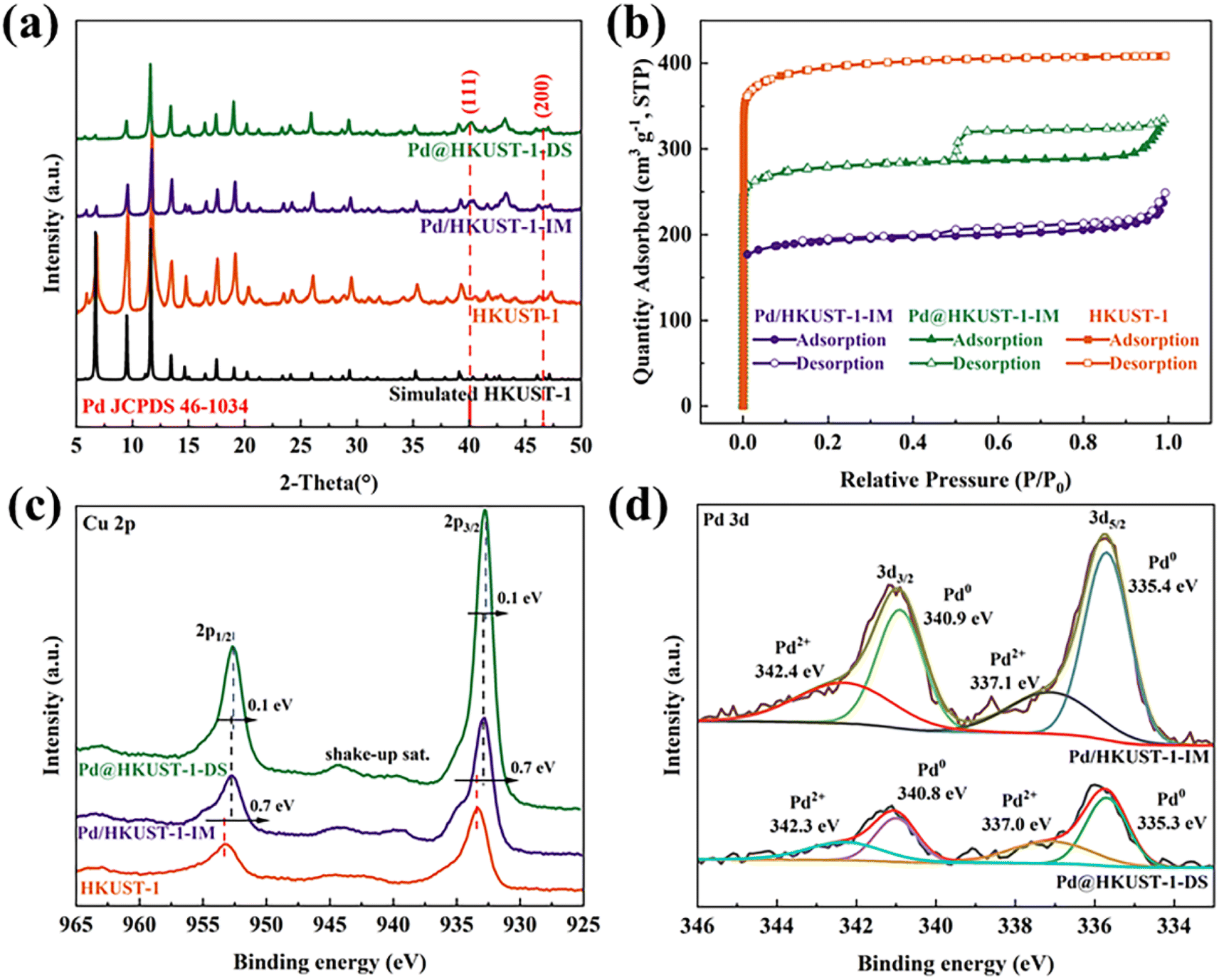 | ||
| Fig. 1 (a) XRD patterns of HKUST-1, Pd@HKUST-1-DS and Pd/HKUST-1-IM. (b) N2 adsorption–desorption isotherms of HKUST-1, Pd@HKUST-1-DS and Pd/HKUST-1-IM measured at 77 K. P: partial pressure of argon, P0 = 1 atm. STP: standard temperature and pressure. (c) Cu 2p XPS spectra of Pd@HKUST-1-DS and Pd/HKUST-1-IM. (d) Pd 3d XPS spectra of Pd@HKUST-1-DS and Pd/HKUST-1-IM. | ||
The textural properties of the as synthesized samples (specific surface area, pore volume and pore size) were further analyzed by N2 sorption experiment at 77 K. As shown in Fig. 1b, according to the International Union of Pure and Applied Chemistry (IUPAC) classification,37 HKUST-1 displays a type I curve originating from the micro-porosity. After loading Pd metal into HKUST-1, both isotherms of Pd@HKUST-1-DS and Pd/HKUST-1-IM were classified as type I adsorption isotherms with H1 and H4 type hysteresis loops, respectively, indicating that the samples retain the microporous structure as HKUST-1 but possess different pore structures. Generally, hysteresis loop is related to condensation inside the capillaries of porous structures, and appear in a wide relative pressure (P/P0) range of 0.45–0.95.38 For Pd@HKUST-1-DS its almost vertical and parallel pore structure proves that Pd metal is introduced successfully into the pores of HKUST-1 by using the DS method and does not significantly block pores. In contrast, Pd/HKUST-1-IM possesses some slit-like-shaped or flake particulate material pores, indicating that a part of pores could be blocked with Pd metal. Compared with HKUST-1, shown in Table S1,† the specific surface areas of Pd@HKUST-1-DS and Pd/HKUST-1-IM are reduced to 1456.22 and 612.84 m2 g−1, respectively. While Pd@HKUST-1-DS shows an average pore size of 8.04 Å, no average pore size of Pd/HKUST-1-IM under 10 Å is obtained. Their decreased physical properties are caused by the occupied pore space and increased weight by Pd metal.39 The differences in textural properties will give rise to different numbers of adsorption sites at the adsorbent surface and inner pores, and then affect hydrogen storage capacity.
The surface chemical states and the change of electronic structure for Cu and Pd of Pd@HKUST-1-DS and Pd/HKUST-1-IM were analyzed by XPS. According to the full XPS spectra in Fig. S1,† there are obvious peaks of Cu 2p, Pd 3d, O 1s and C 1s for both samples. The Cu 2p and Pd 3d binding energies are listed in Table S2.† In Fig. 1c, the Cu 2p binding energies of Pd@HKUST-1-DS and Pd/HKUST-1-IM shifted to lower energy than that of HKUST-1, indicating the occurrence of partial Cu2+ reduction. The well-known shake-up satellite bands observed in the ranges of 961–965 and 938–946 eV further illustrate the existence of Cu2+ species in the Pd-functionalized HKUST-1,40,41 in good agreement with that of HKUST-1.42 In contrast, the Pd 3d binding energies of Pd@HKUST-1-DS and Pd/HKUST-1-IM in Fig. 1d are shifted to higher energy in comparison with the Pd nanocubes, which indicates that partial Pd oxidization state occurs. This is attributed to the interaction of the electron-donating Pd0 species with the neighboring (H+) protons during material synthesis.43,44 Based on the further analysis of Pd 3d, the Pd 3d spectrum of Pd@HKUST-1-DS (Pd/HKUST-1) was deconvoluted into four central binding energies at 340.9 eV, 335.4 eV (340.8 eV, 335.3 eV) and 342.4 eV, 337.1 eV (342.3 eV, 337.0), corresponding to the peaks of Pd0 and Pd2+ species, respectively. Importantly, both Pd-functionalized HKUST-1 show different changes in the electronic structure of Cu and Pd. Compared with Pd/HKUST-1-IM, the Cu 2p binding energies for Pd@HKUST-1-DS are lower and their binding energy difference is 0.1 eV, while the Pd 3d binding energies of Pd@HKUST-1-DS shift to higher energy. The above results indicate that more electrons of Pd nanoparticles for Pd@HKUST-1-DS are transferred to the HKUST-1 support, in comparison with Pd/HKUST-1-IM. The hydrogen concentration in the Pd is positively correlated with the number of Pd 4d-band holes,45 while electron transfer between Pd and the support can improve.46,47 Thus, the Pd@HKUST-1-DS with more electron transfer may possess more holes in the 4d band of Pd nanoparticles, leading to the enhanced hydrogen storage capacity.
The micro-structures of Pd@HKUST-1-DS and Pd/HKUST-1-IM materials were characterized by SEM and TEM. As shown in Fig. 2a and b, following the traditional impregnation–reduction method, the morphology of well-defined octahedrons with a diameter of around 12.5 μm can be found in Pd/HKUST-1-IM. It is worth noting that the “rough” surface of Pd/HKUST-1-IM can be attributed to the removal of some water molecules from the material framework after impregnation–reduction treatment. Based on at least 100 particles, displayed in Fig. S4a,† the average Pt particle diameter (darker areas) in Pd/HKUST-1-IM catalysts is determined to be 4.44 ± 0.06 nm, which is larger than the largest cavity of HKUST-1 and may cause sample pore blockage. For Pd@HKUST-1-DS, it shows a similar morphology of octahedrons with a diameter of around 9.83 μm in Fig. 2c. What's more, the TEM images in Fig. 2c and S4b† prove that compared to Pd/HKUST-1-IM, the Pd@HKUST-1-DS possesses a narrow and highly dispersed particle size distribution between 1 and 5 nm with a mean particle size of 2.05 ± 0.07 nm. Importantly, the two areas including bright spots and without bright spots in the dark field TEM image of Pd@HKUST-1-DS (Fig. 2e) prove the successful introduction of Pd nanoparticles into the confined pore space of HKUST-1 and the high dispersion of Pd particles on the external surface by the corresponding EDS mapping (Fig. 2f–h). It is reasonably considered that it is more difficult to achieve through the traditional impregnation method in comparison to the DS approach. The different Pd nanoparticles with different sizes and disparities could affect the hydrogen adsorption of materials.
 | ||
| Fig. 2 (a) SEM images of Pd/HKUST-1-IM, (b) TEM images of Pd/HKUST-1-IM, (c) SEM images of Pd@HKUST-1-DS, (d) TEM images of Pd@HKUST-1-DS, and (e–h) the images of EDS mapping of Cu and Pd for Pd@HKUST-1-DS. | ||
3.2. H2 adsorption and storage
The hydrogen storage capacity at 77 K is measured based on a SETARAM PCT-PRO gas adsorption analyzer. As shown in Fig. 3a, low-pressure H2 adsorption isotherms for all samples show type I isotherms of microporous materials in the IUPAC classification scheme. The H2 adsorption capacity of Pd/HKUST-1-IM and Pd@HKUST-1-DS is obviously higher than that of pristine HKUST-1 over the entire pressure scale, indicating that the incorporation of Pd nanoparticles in HKUST-1 can enhance gas adsorption capacity, which is the same as previous reports.48,49 The actual H2 storage capacities at 1 bar and 77 K are presented in Fig. 3b. Pristine HKUST-1 can absorb 1.78 wt% of H2 at 77 K and 1 bar, lower than the previous reports of Morris's group (2.5 wt%),50 because of the textural property differences induced by the purity of samples.51 With the increased pressure from 1 bar to 2 bar, the actual H2 uptake of HKUST-1 is improved to 2.49 wt%. For Pd-functionalized HKUST-1, both Pd/HKUST-1-IM and Pd@HKUST-1-DS show enhanced H2 uptakes of 47% (30%) and 66% (47%) in comparison with HKUST-1 at 1 bar (or 2 bar), respectively. As a result, H2 uptake of Pd@HKUST-1-DS reaches as high as 3.68 wt% at 77 K and 2 bar, which indicates a significant improvement over impregnated Pd/HKUST-1-IM (3.24 wt%) and pristine HKUST-1 (2.49 wt%) under the same condition. After H2 adsorption at 77 K, as shown in Fig. S5a,† the desorption kinetic curves indicate that Pd/HKUST-1-IM and Pd@HKUST-1-DS can almost release all absorbed hydrogen in four min at 200 K, while the kinetics of hydrogen desorption in Pd@HKUST-1-DS is faster than that of Pd/HKUST-1-IM. | ||
| Fig. 3 Hydrogen adsorption isotherms of HKUST-1, Pd@HKUST-1 and Pd/HKUST-1 at 77 K up to 2 bar H2: (a) hydrogen adsorption isotherms; (b) actual H2 adsorption at 1 bar. | ||
The hydrogen storage capacity of Pd-functionalized HKUST-1 was further evaluated at 298 K and in the range of 0–18 MPa. Generally, HKUST-1 can withstand pressures greater than 2000 MPa regardless of the guest molecules,52 and thus the mechanical stability of materials does not need to be concerned under the operating conditions of this study. As shown in Fig. 4, pristine HKUST-1 has a linear hydrogen isotherm with the actual maximum H2 uptake of 0.49 wt% at 14 MPa, in agreement with the previous literature (0.35 wt% at ∼6.5 MPa (ref. 53) and approximately 0.65 wt% at 20 MPa (ref. 31)), which indicates that the adsorption of hydrogen on HKUST-1 is mainly derived from the physisorption behavior based on the Chahine rule which associates hydrogen uptake with the specific surface area (SSA) linearly.54 For Pd-functionalized HKUST-1, the hydrogen isotherms of Pd/HKUST-1-IM and Pd@HKUST-1-DS increased slowly at first under 2 MPa and then increased rapidly in the pressure range of 2–18 MPa. The maximum H2 uptakes for Pd/HKUST-1-IM and Pd@HKUST-1-DS at 18 MPa are 1.14 wt% and 1.63 wt% respectively, which are higher than that of HKUST-1. The H2 desorption isotherm indicates, in Fig. S5b,† that with decreasing pressure, hydrogen can be completely desorbed from the two Pd-functionalized HKUST-1 at 298 K, in correspondence with previous reports. The room-temperature hydrogen storage capacity for previous materials with noble metals is compared with the present results in Table S3.† The hydrogen storage capacity of Pd@HKUST-1-DS is slightly lower than that of other materials with noble metals under the same condition due to low SSA and low Pd amount. In general, the Pd NPs are considered as an effective active metal for hydrogen adsorption and storage.49,55,56 The introduction of Pd NPs into the MOFs can bring the spillover effect and enhance the hydrogen storage capacity of MOFs. Our results confirm that H2 uptake of materials is obviously affected by the incorporation of Pd NPs into MOFs at 77 K and 298 K, and the doping of HKUST-1 with Pd NPs is a key factor to improve their hydrogen storage capacity due to the hydrogen spillover effect. However, both Pd@HKUST-1-DS and Pd/HKUST-1-IM with the same Pd amount exhibit completely different H2 adsorption capacities at 77 K and 298 K. The resulting Pd@HKUST-1-DS exhibits higher H2 uptakes with an enhancement of 13% and 43% than Pd/HKUST-1-IM at 77 K and 298 K, respectively. Considering that all the doped samples use the same support and possess the same Pd volume, this means that the enhancement of hydrogen storage capacity of different Pd doped HKUTS-1 samples can be affected by other factors including (1) physisorption of hydrogen molecules on materials with different textural properties,57 (2) hydride formation of Pd particles with H2,58 and (3) hydrogen spillover and subsequent chemisorption to the support or recombination to physisorbed H2,59 which is discussed below.
 | ||
| Fig. 4 Hydrogen adsorption isotherms of HKUST-1, Pd@HKUST-1 and Pd/HKUST-1 at 298 K up to 18 MPa H2. | ||
Based on the BET results, as shown in Table S1,† it was found that the textural properties of Pd-functionalized materials, obtained by using different doping techniques, are significantly affected. Compared with the impregnated Pd/HKUST-1-IM, the Pd@/HKUST-1-DS exhibits a high specific surface area (1033.88 m2 g−1), large micropore volume (0.35 cm3 g−1), and small average pore size (8.04 Å) with no blocking. Generally, the amount of hydrogen physisorbed depends almost linearly on the SSA of materials both at low temperature and at room temperature.7,57 Thus, when only the differences in textural properties of materials are considered, Pd@HKUST-1-DS can adsorb more hydrogen than Pd/HKUST-1-IM.
The effect of chemisorption on hydrogen storage for Pd-functionalized HKUST-1 materials was further discussed by using pure H2 TDS measurements at 77 K.33,59 As shown in Fig. 5a, the spectra for HKUST-1 show a sharp and narrow desorption peak centered around 92 K, which can be attributed to the physisorption of materials. Pd@HKUST-1-DS exhibits two desorption peaks, including a broad peak around 96 K and a broad shoulder peak around 136 K, indicating the presence of at least two adsorption sites and the occurrence of Pd chemisorption. These two peaks of desorbed hydrogen were assigned to the hydrogen desorption of interior pores (site I) and the hydrogen release from the interstitial sites of the single β-phase PdHx (site II).60 Although similar spectra can also be found in Pd/HKUST-1-IM, the spectra of its site I show a desorption process that rises irregularly and gradually due to uneven Pd NP dispersion and partially blocked pores. Meanwhile, a lower central desorption temperature of site II (118 K) for Pd/HKUST-1-IM indicates weaker interaction of hydrogen molecules with Pd than Pd@HKUST-1-DS and can affect the hydrogen adsorption storage of the material. The quick kinetics and the high hydrogen storage capacity of Pd@HKUST-1-DS in Fig. S2† also indicate the enhancement in the kinetics of hydrogen storage in comparison with other materials. It is worth noting that no obvious spectra for both Pd/HKUST-1-IM and Pd@HKUST-1-DS above 200 K occur, since the change from the β-phase to α-phase of PdHx on materials and subsequently the α-phase dehydrogenation have not occurred at low pressure. Considering the desorption intensity and temperature maximum, both two sites of Pd@HKUST-1-DS exhibit stronger H2 adsorption than those of Pd/HKUST-1-IM, leading to a high hydrogen storage capacity at 77 K and 298 K.
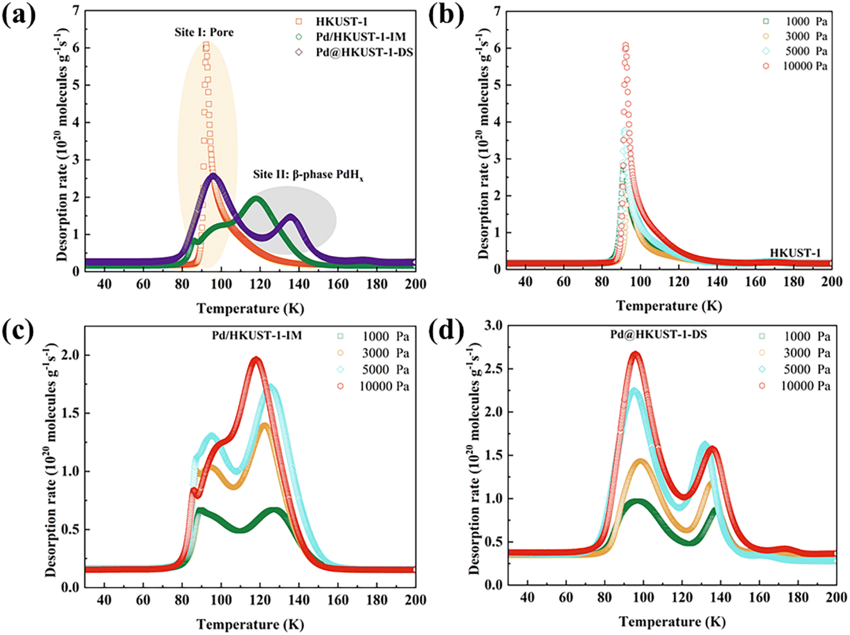 | ||
Fig. 5 Thermal desorption spectra of HKUST-1, Pd@HKUST-1 and Pd/HKUST-1 at 77 K: (a) comparison in 10![[thin space (1/6-em)]](https://www.rsc.org/images/entities/char_2009.gif) 000 Pa of pure H2. (b) Series of different concentrations of pure H2 for HKUST-1. (c) Series of different concentrations of pure H2 for Pd/HKUST-1. (d) Series of different concentrations of pure H2 for Pd@HKUST-1. The sample was exposed to a known quantity of H2 at 77 K for 10 min and then was evacuated for 2 min before heating at a rate of 6 K min−1. 000 Pa of pure H2. (b) Series of different concentrations of pure H2 for HKUST-1. (c) Series of different concentrations of pure H2 for Pd/HKUST-1. (d) Series of different concentrations of pure H2 for Pd@HKUST-1. The sample was exposed to a known quantity of H2 at 77 K for 10 min and then was evacuated for 2 min before heating at a rate of 6 K min−1. | ||
The sequential filling of different sites for Pd-functionalized HKUST-1 can be further explored under various loading pressures by using the TDS measurements, as displayed in Fig. 5b–d. In general, the increased peak intensity should correspond to the amount of gas originally adsorbed at the corresponding site. The site peak of HKUST-1 (Fig. 5b) increases with rising loading pressure. For Pd-functionalized HKUST-1, as loading pressure rises, the site II peak of Pd/HKUST-1-IM (Fig. 5c) shows an obvious change, except the peak from site I. For site I, its intensity first increases rapidly and then decreases with rising pressure from 1000 to 10000 Pa, since the blocked pore structure cannot adsorb more hydrogen. In contrast, the peak intensity of both sites of Pd@HKUST-1-DS (Fig. 5d) increases with increasing loading pressure. The intensity of site I increases faster than that of site II because more electron transfer bands, more holes in the 4d band of Pd nanoparticles enhance the interaction, and the blocking of pore space of the material does not occur. Therefore, the preferential sites of Pd/HKUST-1-IM and Pd@HKUST-1-DS for hydrogen are site II and site I, respectively.
The spillover effect was proved by a pure H2 TDS experiment at room temperature. As shown in Fig. S3,† before loading H2 pressure, the spectra of Pd@HKUST-1-DS do not show any signal of H2 and H2O in the temperature range of 303–473 K owing to the reduction treatment of the sample and the in situ activation of samples within the device. After loading pressure in Fig. 6, with the increased temperature, the H2-loading Pd@HKUST-1-DS exhibits firstly the signal of H2 and then the signal of H2O. The initial desorption temperatures for both H2 and H2O signals are approximately 326 and 379 K, respectively. The increased signal of H2 under 379 K corresponds to the hydrogen adsorbed on the pore spaces of Pd@HKUST-1 and the physisorption of the support. When the temperature rises above 379 K, the rapidly enhancing H2 signal can be related to the hydrogen spillover effect.33 This step consists of three reactions, including (1) the reduction of PdO formed by chemisorbed oxygen atoms over the Pd surface (PdO + H2 → Pd + H2O), (2) the dissociation of H2 molecules and the formation of PdHx (H2 → 2H+ and Pd + xH+ → PdHx), and (3) the desorption of H2 from PdHx at low pressure (PdHx → Pd + 0.5xH2), which can be proved by the clearly increased H2O signal and is similar to the previous literature.33 Considering the thermostability of materials, the continuously growing H2O signal at above 453 K can be attributed to the dehydration process of the HKUST-1 support. The high distribution of Pd nanoparticles on the surface of Pd@HKUST-1-DS can enhance the hydrogen spillover effect,47,59 which enhances the hydrogen storage capacity of Pd@HKUST-1-DS at 298 K.
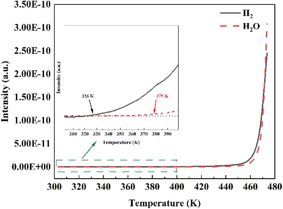 | ||
| Fig. 6 Thermal desorption spectra of Pd@HKUST-1-DS at 298 K and in 20000 Pa of pure H2. The sample was exposed to a known quantity of H2 at 298 K for 20 min and then was evacuated for 5 min before heating at a rate of 5 K min−1. Inset: the magnification of TDS spectra in the temperature range of 303–400 K. | ||
From the above discussed results, it is clearly seen that the DS method can effectively confine Pd NPs into the pore space of HKUST-1, in comparison with the impregnation approach, leading to more electron transport from Pd NPs to the HKUST-1 support and strong interaction of the pore and surface with H2, and spillover effect on the surface. What's more, this approach does not lead to the sharp reduction of SSA and blocking of pores in Pd@HKUST-1-DS. The results indicate that an appropriate synthesis for materials with noble metals can enhance hydrogen storage capacity, and Pd@HKUST-1-DS shows a high hydrogen uptake in comparison with HKUST-1 and Pd/HKUST-1-IM, due to strong interaction of the pore with hydrogen and spillover effect on the surface of the material, displayed in Fig. 7.
 | ||
| Fig. 7 Effect of Pd NPs with HKUST-1 on high-pressure. | ||
4. Conclusions
In summary, we have attempted at doping Pd NPs into the pore space of HKUST-1 for low and room temperature hydrogen storage at high pressure. Different Pt-functionalized HKUST-1 materials (Pd@/HKUST-1-DS and Pd/HKUST-1-IM) are tested. It is found that different methods can bring different textural properties and interaction of the metal with the support, leading to the difference of hydrogen storage capacity. The Pd@/HKUST-1-DS interaction was further analyzed by XPS and TDS. What's more, the DS method does not cause the sharp reduction of the SSA and the blocking of pores in Pd@/HKUST-1-DS. The results indicate that in contrast to impregnated Pd/HKUST-1-IM, Pd@HKUST-1-DS shows more electron transport of Pd NPs to the HKUST-1 support and strong interaction of pores with hydrogen. Two desorption maxima were observed in Pd@HKUST-1-DS and Pd/HKUST-1-IM, which are assigned to different adsorption sites, including pores and Pd NPs. The Pd NPs of Pd/HKUST-1-IM were preferentially occupied by hydrogen molecules, while the pore site is the main adsorption site for Pd@HKUST-1-DS. Benefiting from the strong interaction of pores and hydrogen, spillover effect of the material surface and high SSA, the prepared Pd@/HKUST-1-DS has a higher hydrogen storage capacity of 3.68 wt% at 77 K and 2 MPa, which even reaches 1.63 wt% at 298 K and 18 MPa. Furthermore, our work indicates the importance of a suitable synthesis method for synthesizing materials with noble metals for hydrogen storage, and the effect of strong interaction on improving the hydrogen storage capacity of materials at low and room temperature.Author contributions
Xiaoyu Hu initiated this study, and synthesized, characterized, tested materials. And Jinchuan Wang, Rongxing Ye, and Shangkun Li provided guidance on TDS measurement and adsorption experiment, respectively. Xuanhao Hu and Linsen Zhou contributed to the characterization section. Peilong Li and Changlun Chen provided project support and supervision. All authors contributed to writing/revising the paper.Conflicts of interest
The authors declare no conflicts of interest.Acknowledgements
The authors gratefully acknowledge the financial supports by the National Key Research and Development Program of China (No. 2022YFE03170001), Sichuan Science and Technology Program (No. 2020YFQ0005), the National Natural Science Foundation of China (No. 22276194), and the Presidential Foundation of Hefei Institutes of Physical Science, Chinese Academy of Sciences (No. YZJJZX202019).References
- L. Xue, A. Ding, O. Cooper, X. Huang, W. Wang, D. Zhou, Z. Wu, A. McClure-Begley, I. Petropavlovskikh, M. O. Andreae and C. Fu, Natl. Sci. Rev., 2020, 8, nwaa132, DOI:10.1093/nsr/nwaa132.
- R. Winkelmann, A. Levermann, A. Ridgwell and K. Caldeira, Sci. Adv., 2015, 1, e1500589, DOI:10.1126/sciadv.1500589.
- R. Lal, Land Degrad. Dev., 2009, 20, 441–454, DOI:10.1002/ldr.934.
- L. M. Germeshuizen and P. W. E. Blom, Int. J. Hydrogen Energy, 2013, 38, 10671–10682, DOI:10.1016/j.ijhydene.2013.06.076.
- M. Ashokkumar, Int. J. Hydrogen Energy, 1998, 23, 427–438, DOI:10.1016/S0360-3199(97)00103-1.
- Y. Xia, Z. Yang and Y. Zhu, J. Mater. Chem. A, 2013, 1, 9365–9381, 10.1039/C3TA10583K.
- H. W. Langmi, J. Ren, B. North, M. Mathe and D. Bessarabov, Electrochim. Acta, 2014, 128, 368–392, DOI:10.1016/j.electacta.2013.10.190.
- S. Banerjee, S. Murad and I. K. Puri, Proc. IEEE, 2006, 94, 1806–1814, DOI:10.1109/JPROC.2006.883703.
- W. C. Xu, K. Takahashi, Y. Matsuo, Y. Hattori, M. Kumagai, S. Ishiyama, K. Kaneko and S. Iijima, Int. J. Hydrogen Energy, 2007, 32, 2504–2512, DOI:10.1016/j.ijhydene.2006.11.012.
- M. Wu, Q. Zheng, T. Sun and X. Zhang, Int. J. Hydrogen Energy, 2023, 48, 3994–4005, DOI:10.1016/j.ijhydene.2022.10.245.
- Z. Chen, K. O. Kirlikovali, K. B. Idrees, M. C. Wasson and O. K. Farha, Chem, 2022, 8, 693–716, DOI:10.1016/j.chempr.2022.01.012.
- R. V. Denys, V. A. Yartys and C. J. Webb, Inorg. Chem., 2012, 51, 4231–4238, DOI:10.1021/ic202705u.
- X. Feng, L. Jiang, Z. Li, S. Wang, J. Ye, Y. Wu and B. Yuan, Int. J. Hydrogen Energy, 2022, 47, 23994–24003, DOI:10.1016/j.ijhydene.2022.04.234.
- S. Thiangviriya, P. Plerdsranoy, N. Wiset, P. Javadian, T. R. Jensen and R. Utke, J. Alloys Compd., 2015, 633, 484–493, DOI:10.1016/j.jallcom.2015.02.030.
- V. Zeleňák and I. Saldan, Nanomaterials, 2021, 11, 1638, DOI:10.3390/nano11071638.
- Z. W. Zhu and Q. R. Zheng, Int. J. Hydrogen Energy, 2023, 48, 5166–5174, DOI:10.1016/j.ijhydene.2022.11.026.
- X. Zhao, B. Xiao, A. J. Fletcher, K. M. Thomas, D. Bradshaw and M. J. Rosseinsky, Science, 2004, 306, 1012–1015, DOI:10.1126/science.1101982.
- H. Zhou, J. Zhang, J. Zhang, X. Yan, X. Shen and A. Yuan, Int. J. Hydrogen Energy, 2015, 40, 12275–12285, DOI:10.1016/j.ijhydene.2015.05.199.
- S. J. Alesaadi and F. Sabzi, Int. J. Hydrogen Energy, 2015, 40, 1651–1656, DOI:10.1016/j.ijhydene.2014.12.008.
- A. Ahmed, S. Seth, J. Purewal, A. G. Wong-Foy, M. Veenstra, A. J. Matzger and D. J. Siegel, Nat. Commun., 2019, 10, 1568, DOI:10.1038/s41467-019-09365-w.
- K. S. Vetlitsyna-Novikova, V. V. Butova, I. A. Pankin, V. V. Shapovalov and A. V. Soldatov, J. Surf. Invest.: X-Ray, Synchrotron Neutron Tech., 2019, 13, 787–792, DOI:10.1134/S1027451019050173.
- D. W. Lim, S. A. Chyun and M. P. Suh, Angew. Chem., Int. Ed., 2014, 53, 7819–7822, DOI:10.1002/anie.201404265.
- P. M. Forster, J. Eckert, B. D. Heiken, J. B. Parise, J. W. Yoon, S. H. Jhung, J. S. Chang and A. K. Cheetham, J. Am. Chem. Soc., 2006, 128, 16846–16850, DOI:10.1021/ja0649217.
- X. Qian, R. Zhang, L. Chen, Y. Lei and A. Xu, ACS Sustainable Chem. Eng., 2019, 7, 16007–16012, DOI:10.1021/acssuschemeng.9b02559.
- Y. E. Cheon and M. P. Suh, Chem. Commun., 2009, 17, 2296–2298, 10.1039/B900085B.
- J. A. Botas, G. Calleja, M. Sánchez-Sánchez and M. G. Orcajo, Int. J. Hydrogen Energy, 2011, 36, 10834–10844, DOI:10.1016/j.ijhydene.2011.05.187.
- C. L. Chu, J. R. Chen and T. Y. Lee, Int. J. Hydrogen Energy, 2012, 37, 6721–6726, DOI:10.1016/j.ijhydene.2012.01.046.
- N. M. Rodrigues, J. R. S. Politi and J. B. L. Martins, Comput. Mater. Sci., 2022, 210, 111438, DOI:10.1016/j.commatsci.2022.111438.
- W. W. He, S. L. Li, W. L. Li, J. S. Li, G. S. Yang, S. R. Zhang, Y. Q. Lan, P. Shen and Z. M. Su, J. Mater. Chem. A, 2013, 1, 11111–11116, 10.1039/C3TA12662E.
- B. Zielinska, B. Michalkiewicz, X. Chen, E. Mijowska and R. J. Kalenczuk, Chem. Phys. Lett., 2016, 647, 14–19, DOI:10.1016/j.cplett.2016.01.036.
- S. V. Chuvikov, E. A. Berdonosova, A. Krautsou, J. V. Kostina, V. V. Minin, E. A. Ugolkova and S. N. Klyamkin, Phys. Chem. Chem. Phys., 2021, 23, 4277–4286, 10.1039/D0CP03900D.
- P. C. Kang, Y. S. Ou, G. L. Li, J. K. Chang and C. Y. Wang, ACS Appl. Nano Mater., 2021, 4, 11269–11280, DOI:10.1021/acsanm.1c02862.
- J. A. Villajos, G. Orcajo, G. Calleja, J. A. Botas and C. Martos, Int. J. Hydrogen Energy, 2016, 41, 19439–19446, DOI:10.1016/j.ijhydene.2016.05.143.
- Y. Cao, Y. Zhao, F. Song and Q. Zhong, J. Energy Chem., 2014, 23, 468–474, DOI:10.1016/S2095-4956(14)60173-X.
- E. Biemmi, S. Christian, N. Stock and T. Bein, Microporous Mesoporous Mater., 2009, 117, 111–117, DOI:10.1016/j.micromeso.2008.06.040.
- Q. Wu, C. Shen and C. J. Liu, Appl. Surf. Sci., 2023, 607, 154976, DOI:10.1016/j.apsusc.2022.154976.
- G. Leofanti, M. Padovan, G. Tozzola and B. Venturelli, Catal. Today, 1998, 41, 207–219, DOI:10.1016/S0920-5861(98)00050-9.
- S. Yurdakal, C. Garlisi, L. Özcan, M. Bellardita and G. Palmisano, Heterog. Photocatal., 2019, 87–152, DOI:10.1016/B978-0-444-64015-4.00004-3.
- Z. Guo, C. Xiao, R. V. Maligal-Ganesh, L. Zhou, T. W. Goh, X. Li, D. Tesfagaber, A. Thiel and W. Huang, ACS Catal., 2014, 4, 1340–1348, DOI:10.1021/cs400982n.
- H. Chen, L. Wang, J. Yang and R. T. Yang, J. Phys. Chem. C, 2013, 117, 7565–7576, DOI:10.1021/jp401367k.
- X. Hu, F. Ding, R. Xiong, Y. An, X. Feng, J. Song, L. Zhou, P. Li and C. Chen, ACS Appl. Mater. Interfaces, 2023, 15, 3941–3952, DOI:10.1021/acsami.2c18221.
- Q. X. Luo, B. W. An, M. Ji, S. E. Park, C. Hao and Y. Q. Li, J. Porous Mater., 2014, 22, 247–259, DOI:10.1007/s10934-014-9891-7.
- J. Y. Kim, Y. Jo, J. D. Kim, M. Y. Choi, S. Lee and H. C. Choi, Chemosphere, 2022, 307, 135838, DOI:10.1016/j.chemosphere.2022.135838.
- L. M. Gómez-Sainero, X. L. Seoane, J. L. G. Fierro and A. Arcoya, J. Catal., 2002, 209, 279–288, DOI:10.1006/jcat.2002.3655.
- D. A. Papaconstantopoulos, B. M. Klein, E. N. Economou and L. L. Boyer, Phys. Rev. B: Solid State, 1978, 17, 141–150, DOI:10.1103/PhysRevB.17.141.
- G. Li, H. Kobayashi, J. M. Taylor, R. Ikeda, Y. Kubota, K. Kato, M. Takata, T. Yamamoto, S. Toh, S. Matsumura and H. Kitagawa, Nat. Mater., 2014, 13, 802–806, DOI:10.1038/nmat4030.
- C. Zlotea, R. Campesi, F. Cuevas, E. Leroy, P. Dibandjo, C. Volkringer, T. Loiseau, G. Férey and M. Latroche, J. Am. Chem. Soc., 2010, 132, 2991–2997, DOI:10.1021/ja9084995.
- C. Zhou and J. A. Szpunar, ACS Appl. Mater. Interfaces, 2016, 8, 25933–25940, DOI:10.1021/acsami.6b07122.
- A. G. Wong-Foy, A. J. Matzger and O. M. Yaghi, J. Am. Chem. Soc., 2006, 128, 3494–3495, DOI:10.1021/ja058213h.
- B. Xiao, P. S. Wheatley, X. Zhao, A. J. Fletcher, S. Fox, A. G. Rossi, I. L. Megson, S. Bordiga, L. Regli, K. M. Thomas and R. E. Morris, J. Am. Chem. Soc., 2007, 129, 1203–1209, DOI:10.1021/ja066098k.
- K. Yang, G. Zhou and Q. Xu, RSC Adv., 2016, 6, 37506–37514, 10.1039/C5RA23149C.
- B. Panella, M. Hirscher, H. Pütter and U. Müller, Adv. Funct. Mater., 2006, 16, 520–524, DOI:10.1002/adfm.200500561.
- C. Y. Wang, C. W. Chang, Y. J. Wu and A. D. Lueking, Curr. Opin. Chem. Eng., 2018, 21, 116–121, DOI:10.1016/j.coche.2018.10.005.
- C. K. Back, G. Sandí, J. Prakash and J. Hranisavljevic, J. Phys. Chem. B, 2006, 110, 16225–16231, DOI:10.1021/jp061925p.
- Z. Gohari Bajestani, A. Yürüm and Y. Yürüm, Int. J. Hydrogen Energy, 2016, 41, 9810–9818, DOI:10.1016/j.ijhydene.2016.03.201.
- M. Hirscher and B. Panella, J. Alloys Compd., 2005, 404–406, 399–401, DOI:10.1016/j.jallcom.2004.11.109.
- C. I. Contescu, K. van Benthem, S. Li, C. S. Bonifacio, S. J. Pennycook, P. Jena and N. C. Gallego, Carbon, 2011, 49, 4050–4058, DOI:10.1016/j.carbon.2011.05.021.
- L. Zubizarreta, J. A. Menéndez, J. J. Pis and A. Arenillas, Int. J. Hydrogen Energy, 2009, 34, 3070–3076, DOI:10.1016/j.ijhydene.2009.01.040.
- V. A. Vons, H. Leegwater, W. J. Legerstee, S. W. H. Eijt and A. Schmidt-Ott, Int. J. Hydrogen Energy, 2010, 35, 5479–5489, DOI:10.1016/j.ijhydene.2010.02.118.
- C. M. Ghimbeu, C. Zlotea, R. Gadiou, F. Cuevas, E. Leroy, M. Latroche and C. Vix-Guterl, J. Mater. Chem., 2011, 21, 17765–17775, 10.1039/C1JM12939B.
Footnote |
| † Electronic supplementary information (ESI) available. See DOI: https://doi.org/10.1039/d3ra01788e |
| This journal is © The Royal Society of Chemistry 2023 |