DOI:
10.1039/D3RA01657A
(Paper)
RSC Adv., 2023,
13, 14139-14149
Electrochemical capacitance properties of pre-sodiated manganese oxide for aqueous Na-ion supercapacitors†
Received
13th March 2023
, Accepted 30th April 2023
First published on 9th May 2023
Abstract
Mn-based oxides are widely investigated as electrode materials for electrochemical supercapacitors, because of their high specific capacitance in addition to the high abundance, low cost, and environmental friendliness of Mn. The pre-insertion of alkali metal ions is found to improve the capacitance properties of MnO2. While the capacitance properties of MnO2, Mn2O3, P2-Na0.5MnO2, and O3-NaMnO2 etc. are reported, there is no report yet on the capacitive performance of P2-Na2/3MnO2, which has already been studied as a potential positive electrode material for Na-ion batteries. In this work, we have synthesized sodiated manganese oxide, P2-Na2/3MnO2 by a hydrothermal method followed by annealing at a high temperature of about 900 °C for 12 h. For comparison, manganese oxide Mn2O3 (without pre-sodiation) is synthesized by following the same method, but annealing at 400 °C. While P2-Na2/3MnO2 exhibits a high specific capacitance of 234 F g−1, Mn2O3 can deliver only 115 F g−1 when cycled at 0.4 A g−1 in an aqueous electrolyte of 1.0 M Na2SO4 in a three-electrode cell. An asymmetric supercapacitor Na2/3MnO2‖AC is assembled, which can exhibit a SC of 37.7 F g−1 at 0.1 A g−1 with an energy density of 20.9 W h kg−1, based on the total weight of Na2/3MnO2 and AC with an operational voltage of 2.0 V and possesses excellent cycling stability. This asymmetric Na2/3MnO2‖AC supercapacitor can be cost-effective considering the high abundance, low-cost and environmental friendliness of Mn-based oxides and aqueous Na2SO4 electrolyte.
1. Introduction
There is growing research interest in electrochemical supercapacitors because of their high-power density and long cycle-life.1–6 While batteries possess high energy density (>50 W h kg−1), conventional capacitors exhibit a high-power density of 103 kW kg−1. Electrochemical supercapacitors possessing intermediate energy density (5–10 W h kg−1) and power density (>103 W kg−1) bridge the gap between them.1,6 Currently, aqueous Zn-ion hybrid capacitors and batteries with higher energy to power ratio find great potential to overcome the low energy density of aqueous supercapacitors.7,8 While supercapacitors can find many applications, these can be used complementary to batteries in electric vehicles where they can withstand high pulse power. Depending on the charge storage mechanism, there are two types of supercapacitors, namely electrical double-layer capacitors, where the capacitance arises due to the physisorption of ions from/to the electrode, and pseudo-capacitors involving the Faradaic redox reaction of active material.9–11 The double-layer capacitance of activated carbon (AC) is limited to 100–250 F g−1 depending on the surface area of the AC sample as well as the electrolyte used.12,13 Pseudo-capacitances of transition metal oxides are found to be higher than the double-layer SC of AC. Among transition metal oxides, RuO2 is a promising electrode material, because of its high SC of 700–800 F g−1.14–17 However, low-cost and environment-friendly metal oxides such as MnO2, NiO, Ni(OH)2, NiCo2O4 are widely studied as alternatives to toxic and costly RuO2.18–27 For example, Munawar et al. synthesized flower-like NiO by a surfactant-assisted method, which exhibited a SC of 397 F g−1 at a specific current of 1 A g−1.26 Recently, Yewale et al. synthesized plate-like NiCo2O4 by a hydrothermal method, which exhibited a SC of 550 F g−1.27 Also, there is growing interest on transition metal sulfides such as CuCo2S4, Co3S4, NiCo2S4 etc., because of their high specific capacitance values.28–31 Abuali et al. synthesized CuCo2S4 nanoparticles in polyaniline hollow spheres, which can exhibit a SC of 1120 F g−1 at a specific current of 1 A g−1.29 However, these materials exhibit their capacitance properties in alkali solutions, which are not environmentally friendly.
Mn-based cheap oxides can exhibit SC of 150–300 F g−1 depending on the crystallographic form, morphology and the nature of the aqueous electrolyte used. The pre-insertion of alkali metal ions (Na+, K+) is found to influence the capacitance properties of MnO2.32,33 While the capacitance properties of MnO2, Na0.21MnO2, Na0.5MnO2, and NaMnO2 etc. are well studied and reported, the performance of P2-Na2/3MnO2 (which has been investigated as a potential positive electrode material for Na-ion batteries) is not yet studied. The capacitive performance of MnO2 and alkali metal ion pre-inserted MnO2 are listed along with our current work in Table 1.32–42
Table 1 Specific capacitances of Mn-based oxides in an aqueous Na2SO4 electrolyte
| Electrode material |
Electrolyte |
Potential |
Specific capacitance |
Reference |
| Mesoporous MnO2 |
0.1 M Na2SO4 |
0–1.0 V |
190 F g−1 (1 A g−1) |
37 |
| Mesoporous MnO2 |
0.1 M Ca(NO3)2 |
0–1.0 |
240 F g−1 (1.0 A g−1) |
38 |
| α-MnO2 |
0.1 M Na2SO4 |
0–1.0 V |
166 F g−1 (0.2 A g−1) |
39 |
| δ-MnO2 |
1.0 M Na2SO4 |
0–1.0 V |
210 F g−1 (0.3 A g−1) |
40 |
| MnO2 nano wire |
0.1 M Na2SO4 |
0–0.9 V |
350 F g−1 (0.1 mA cm−2) |
41 |
| β-MnO2 nano wire |
1.0 M Na2SO4 |
0–0.8 V |
453 F g−1 (0.5 A g−1) |
42 |
| K0.6MnO2 |
1.0 M KTFSI |
0–1.2 V |
254 F g−1 (1.0 A g−1) |
32 |
| Na0.5MnO2 |
1.0 M Na2SO4 |
0–1.2 V |
287 F g−1 (1.0 A g−1) |
33 |
| Na0.21MnO2 |
0.5 M Na2SO4 |
0–1.3 V |
184 F g−1 (3.0 A g−1) |
34 |
| Na0.35MnO2 |
0.5 M Na2SO4 |
0–1.0 V |
157 F g−1 (0.2 A g−1) |
35 |
| Na0.95MnO2 |
0.5 M Na2SO4 |
0–1.0 V |
95 F g−1 (0.2 A g−1) |
35 |
| NaMnO2 |
0.5 M Na2SO4 |
0–1.1 V |
140 F g−1 (1.0 A g−1) |
36 |
| Na2/3MnO2 |
1.0 M Na2SO4 |
−0.2–1.2 V |
234 F g−1 (0.4 A g−1) |
This work |
The energy density of supercapacitors depends on the specific capacitance of electrode materials and the operating voltage that depends on the stability of the electrolyte. Based on the electrode materials used, there are two types of supercapacitors, namely symmetric as well as asymmetric supercapacitors. The symmetric supercapacitors involving two similar electrodes possess limited energy density due to low operational voltage in aqueous electrolytes. However, asymmetric supercapacitors employing two different types of electrodes can be operated with a higher voltage, thus increasing their energy density as compared to symmetric supercapacitors. Among various asymmetric supercapacitors, MnO2‖AC,43–47 NaMnO2‖AC,34–36,48 and NiCoO2‖AC49–52 are reported to exhibit energy density of 10–30 W h kg−1. Asymmetric supercapacitors based on MnO2‖AC use mostly amorphous MnO2, which does not exhibit good cycling performance. Layered sodiated transition metal oxides are classified as O3 and P2-type depending on the site which Na occupies. P2-Na2/3MnO2 is widely studied as a positive electrode material for rechargeable Na-ion batteries.53–56 Although the electrochemical performance of O3-type NaMnO2 and P2-type Na0.21MnO2 and Na0.5MnO2 for supercapacitor studies is reported, to the best of the authors' knowledge the electrochemical performance of P2-Na2/3MnO2 as a pseudo-capacitive electrode material is not yet evaluated.
In this work, we have synthesized P2-Na2/3MnO2 by a hydrothermal method followed by annealing at 900 °C for 12 h. In order to emphasize the importance of pre-sodiation, manganese oxide without pre-sodiation is synthesized by the same hydrothermal method and then annealing at 400 °C. We have systematically investigated the electrochemical capacitive performance of both materials by cyclic voltammetry and charge–discharge cycling. While P2-Na2/3MnO2 exhibits a SC of 234 F g−1, Mn2O3 can deliver only 115 F g−1 when cycled at 0.4 A g−1 in 1.0 M Na2SO4 electrolyte with good cycling stability over 4000 cycles. Finally, an asymmetric Na2/3MnO2‖AC supercapacitor is assembled using Na2/3MnO2 as a positive and activated carbon as a negative electrode in an aqueous electrolyte of 1.0 M Na2SO4, which exhibits a SC of 37.7 F g−1 within 2.0 V operating voltage with excellent cycling stability over 6000 cycles.
2. Materials and methods
2.1 Materials used
Analytical grade chemicals such as manganese nitrate, sodium nitrate, urea, N-methyl-2-pyrrolidinone (NMP), poly(vinylidene fluoride) (PVDF), commercial activated carbon (AC) powder and sodium sulphate were used as received. Double distilled (DD) water was used to dissolve the metal salts and urea.
2.2 Methods
2.2.1 Synthesis and characterization of Na2/3MnO2. P2-type Na2/3MnO2 was synthesized by a hydrothermal method followed by annealing at 900 °C for 12 h. In a typical preparation, 5.020 g of manganese nitrate and 1.071 g of NaNO3 were dissolved in 40 ml of DD water with stirring. Another solution containing urea was added dropwise to this solution with continuous stirring for 2 h. Then, the solution was transferred to a Teflon-lined stainless-steel autoclave, which is then heated at 150 °C for 12 h. The precipitate was filtered upon cooling to room temperature and dried, which was then heated at 500 °C for 3 h. The obtained sample was ground to powder form and then annealed at 900 °C for 12 h. Mn2O3 was synthesized from manganese nitrate and urea by following the same procedure, however, annealed at 400 °C. The obtained powder samples ware characterized using a Bruker Advance 8 powder X-ray diffractometer (XRD) with monochromatized Cu Kα radiation (λ = 1.54056 Å). The morphology of both samples was examined by scanning electron microscopy (SEM) (FEI, Quanta 200). The transmission electron microscopy (TEM) analysis was performed using a JEM-2100 plus Microscope JEOL (Japan).
2.2.2 Electrode preparation and electrochemical measurements. The active mass (75 wt%) was mixed with 15 wt% of conductive super P carbon and 10 wt% of PVDF binder and ground in a mortar. A few drops of N-methyl-2-pyrrolidinone (NMP) solvent were added to the mixture and ground to obtain a homogeneous slurry. For preparing the AC electrode, the proportion of active mass, super P carbon and PVDF was 80![[thin space (1/6-em)]](https://www.rsc.org/images/entities/char_2009.gif) :
:![[thin space (1/6-em)]](https://www.rsc.org/images/entities/char_2009.gif) 10
10![[thin space (1/6-em)]](https://www.rsc.org/images/entities/char_2009.gif) :
:![[thin space (1/6-em)]](https://www.rsc.org/images/entities/char_2009.gif) 10 by wt%. Electrodes were prepared by repeated brush coating onto graphite foil current collectors (0.30 μm thick) and drying to get the desired mass. The electrodes were finally dried at 100 °C for 6 h in a vacuum oven before assembling for their electrochemical testing. The electrode area was 1.0 cm2 and the loading of the active mass was 1.0 mg cm−2. The cyclic voltammetry (CV) and galvanostatic charge–discharge (GCD) tests of individual electrodes were performed using a three-electrode cell using Pt foil and saturated calomel electrode (SCE) as counter and reference electrodes, respectively, in an aqueous solution of 1.0 M Na2SO4. The experimental results such as the specific capacitance of the Na2/3MnO2 and Mn2O3 are reported here after performing the experiments for at least 2–3 times. The experimental error is within 2–4%. The asymmetric Na2/3MnO2‖AC supercapacitor was assembled using 4 cm × 4 cm electrodes with a commercial cellulose acetate membrane as the separator and tested in a two-electrode cell using an aqueous electrolyte solution of 1.0 M Na2SO4. The electrochemical impedance spectra (EIS) were measured at open circuit potential (OCP) with an AC amplitude of 10 mV in the frequency range of 10 kHz to 0.01 Hz using ZIVE SP1 potentiostat/galvanostat.
10 by wt%. Electrodes were prepared by repeated brush coating onto graphite foil current collectors (0.30 μm thick) and drying to get the desired mass. The electrodes were finally dried at 100 °C for 6 h in a vacuum oven before assembling for their electrochemical testing. The electrode area was 1.0 cm2 and the loading of the active mass was 1.0 mg cm−2. The cyclic voltammetry (CV) and galvanostatic charge–discharge (GCD) tests of individual electrodes were performed using a three-electrode cell using Pt foil and saturated calomel electrode (SCE) as counter and reference electrodes, respectively, in an aqueous solution of 1.0 M Na2SO4. The experimental results such as the specific capacitance of the Na2/3MnO2 and Mn2O3 are reported here after performing the experiments for at least 2–3 times. The experimental error is within 2–4%. The asymmetric Na2/3MnO2‖AC supercapacitor was assembled using 4 cm × 4 cm electrodes with a commercial cellulose acetate membrane as the separator and tested in a two-electrode cell using an aqueous electrolyte solution of 1.0 M Na2SO4. The electrochemical impedance spectra (EIS) were measured at open circuit potential (OCP) with an AC amplitude of 10 mV in the frequency range of 10 kHz to 0.01 Hz using ZIVE SP1 potentiostat/galvanostat.
3. Results and discussion
The XRD pattern measured for the synthesized Na2/3MnO2 powder material (Fig. 1a) matched well with the reported pattern (JCPDF 27-0751).57,58 The XRD peaks at 2θ of 15.8°, 31.83°, 36.29°, 39.63°, 43.62°, 48.72°, 61.95°, 64.73° and 67.09° correspond to (002), (004), (100), (102), (103), (104), (106), (110) and (008), respectively. Na2/3MnO2 crystallizes in hexagonal P63/mmc space group. The alkali Na+ cation occupies the trigonal prismatic site and is sandwiched between the MO2 sheets. The lattice parameters analyzed with Xpert High score are found to be a = b = 2.8802 Å, c = 11.264 Å with cell volume of 80.93 Å3. The XRD pattern of Mn2O3 is matching well with the reported pattern (JCPDF 98-005-1463) and peaks at 2θ of 23.15°, 33.02°, 36.18°, 38.25°, 45.14°, 49.29°, 35.14° and 65.89° correspond to (112), (222), (123), (004), (233), (134), (044) and (226) planes, respectively. The synthesized materials are found to be highly crystalline, indicated by the sharp diffraction peaks as shown in Fig. 1. The morphology of both materials was observed by SEM. A hexagonal plate-like morphology was observed for Na2/3MnO2 and the average particle size is found to be 2.273 μm as shown in Fig. 2a. On the other hand, agglomerated particles were found in case of Mn2O3 (Fig. 2c). The EDX pattern with atomic% of Mn (38.85%) and O (61.15%) in Fig. 2c clearly indicates the formation of Mn2O3. In TEM, the bright-field image (Fig. 3a) again clearly shows the platelet-like morphology of Na2/3MnO2 whereas the selected area electron diffraction shows the crystalline nature of the sample (Fig. 3b). The high-resolution TEM shows fringes with an interplanar spacing of about 0.428 nm corresponding to the (002) plane of hexagonal Na2/3MnO2.
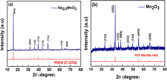 |
| | Fig. 1 XRD patterns of (a) Na2/3MnO2, (b) Mn2O3 synthesized by hydrothermal method followed by annealing. | |
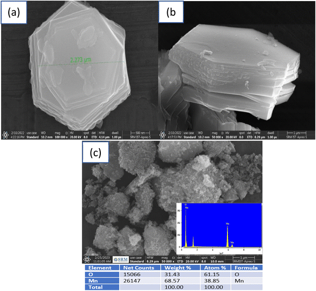 |
| | Fig. 2 SEM images (a) top view and (b) side view of Na2/3MnO2 and (c) Mn2O3 synthesized by hydrothermal method followed by annealing. | |
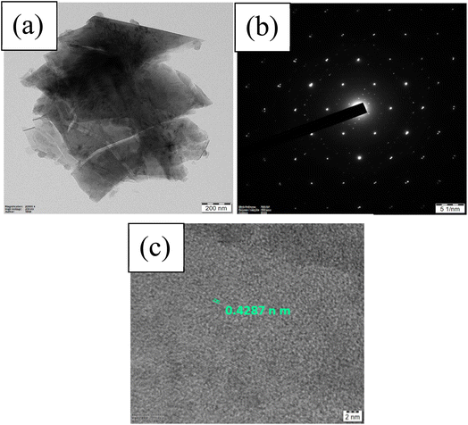 |
| | Fig. 3 TEM results of Na2/3MnO2 showing (a) bright-field image, (b) selected area electron diffraction (SAED) pattern, (c) HRTEM images of Na2/3MnO2 synthesized by hydrothermal method and annealed at 900 °C. | |
The cyclic voltammograms (CVs) of Na2/3MnO2 were carried out at 10 mV s−1 in order to find the suitable potential range where it exhibits the capacitance properties. Rectangular-shaped CV is an indication of ideal double-layer capacitance property whereas CVs with redox peaks indicate the pseudo-capacitance property. A pair of redox peaks at 0.58 V and 0.40 V during anodic and cathodic sweeps, respectively, are clearly observed in the CVs measured (Fig. 4a) in the potential range of −0.2–1.2 V, indicating the pseudo-capacitance of Na2/3MnO2 in a wide potential range. The CVs were repeated at different sweep rates in the potential range of −0.2 to 1.2 V vs. SCE (Fig. 4b). Both the anodic and cathodic peak currents are found to increase with an increase in the sweep rate, indicating a diffusion-controlled electrode process. The peak currents were plotted against the square root of sweep rates, which is found to be linear (Fig. 4c and d). From the slope of these plots, the diffusion coefficient of ions was calculated by using the Randles–Sevcik equation:
| | |
Ip = 0.4463(nFD/RT)1/2ACν1/2
| (1) |
where
Ip is the peak current,
n is the number of electrons transferred in a redox reaction,
F is the Faraday's constant,
R is the universal gas constant,
T is the absolute temperature,
A is the working electrode area (cm
2),
C is the molar concentration of the redox-active species (mol cm
−3),
D is the diffusion coefficient (cm
2 s
−1),
ν is the scan rate (V s
−1). The diffusion coefficient corresponding to anodic and cathodic processes are calculated and found to be 5.1943 × 10
−8 cm
2 s
−1 and 1.7570 × 10
−7 cm
2 s
−1, respectively.
59 In the case of Mn
2O
3, the CVs were found to be mostly rectangular with indistinct peaks when measured at 10 mV s
−1 in the potential range of −0.2–1.2 V, and the CVs were found to be symmetric without deviating from the rectangular shape with increased scan rates (
Fig. 4e and f), similar to the previous report.
60
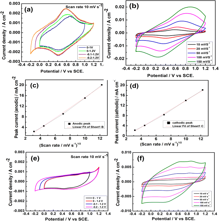 |
| | Fig. 4 (a) Cyclic voltammetry (CV) of Na2/3MnO2 in different potential ranges in an aqueous solution of 1.0 M Na2SO4, (b) CVs of Na2/3MnO2 at different scan rates in −0.2–1.2 V vs. SCE, (c) anodic peak current vs. square root of scan rate, (d) cathodic peak current vs. square root of scan rate, (e) CVs of Mn2O3 in different potential ranges in an aqueous solution of 1.0 M Na2SO4, (f) CVs of Mn2O3 at different scan rates in the potential range of −0.2–1.2 V vs. SCE. | |
Galvanostatic charge–discharge (GCD) cycling is widely used to determine the SC of various electrode materials. The galvanostatic charge–discharge of Na2/3MnO2 and Mn2O3 was carried out at 0.4 A g−1 in various potential ranges of 0–1.0, 0–1.2 and −0.2–1.2 V, which is shown in Fig. 5. The specific capacitances (SC) were evaluated by using the equation:
where
I is the current and (
I/
m) is the specific current,
t is the charge/discharge time and Δ
V is the operating voltage
vs. SCE. It can be seen that the time taken for the charge/discharge for Na
2/3MnO
2 is higher, indicating the higher specific capacitance of Na
2/3MnO
2 over Mn
2O
3. The specific capacitances of Na
2/3MnO
2 and Mn
2O
3 were found to be 249, 226, 234 and 98.8, 102.3, 115.1 F g
−1 at 0.4 A g
−1 in the potential ranges of 0–1.0, 0–1.2 and −0.2–1.2 V, respectively. Thus, Na
2/3MnO
2 exhibits better capacitance property as compared to that of Mn
2O
3 synthesized by following the same hydrothermal method. These SCs of Na
2/3MnO
2 are found to be higher than that of Na
xMnO
2 in an aqueous Na
2SO
4 solution already reported.
32–35 It should be noted that hydrothermally synthesized MnO
2 at 140 °C for 6 h exhibited a SC of only 193 F g
−1 in 1.0 M Na
2SO
4 aqueous solution.
61 Also, SCs in the range of 72–168 F g
−1 were reported for MnO
2 synthesized by the hydrothermal method.
62 Thus, this study clearly indicates the higher SC of hydrothermally synthesized Na
2/3MnO
2 over MnO
2 and Mn
2O
3 when studied in an aqueous solution of Na
2SO
4.
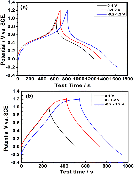 |
| | Fig. 5 Galvanostatic charge–discharge cycling of (a) Na2/3MnO2, (b) Mn2O3 at a current density of 0.4 A g−1 in different potential ranges vs. SCE in an aqueous solution of 1.0 M Na2SO4. | |
The GCD cycling of Na2/3MnO2 and Mn2O3 was carried out at different specific currents, the variation of potential w.r.t. time in the wide potential range of −0.2–1.2 V (Fig. 6a and b) and the plot of SC against the specific currents are shown in Fig. 6c. The SC decreased upon an increase of the specific current in both cases, i.e., for Na2/3MnO2 about 160 F g−1 when cycled at 2 A g−1 and about 90 F g−1 at 10 A g−1 and for Mn2O3, it was about 70.8 F g−1 when cycled at 2 A g−1 and about 36.4 F g−1 at 10 A g−1. Thus, the SC decreased for both samples with an increase in current, which can be due to the decreased utilization of active mass at high currents. However, this result indicates the higher rate capability of Na2/3MnO2 over Mn2O3.
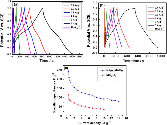 |
| | Fig. 6 Galvanostatic charge–discharge cycling at various specific currents for (a) Na2/3MnO2, (b) Mn2O3, (c) plot of specific capacitances of Na2/3MnO2 and Mn2O3 vs. specific currents in the potential range of −0.2 to 1.2 V vs. SCE. | |
In order to evaluate the long-term cycling stability of Na2/3MnO2 and Mn2O3, the galvanostatic charge–discharge cycling was carried out at 2.0 A g−1 in the potential range of −0.2–1.2 V for about 4000 cycles, which is shown in Fig. 7. The initial SC of Na2/3MnO2 was found to be 165 F g−1, which increased gradually to a value of about 170 F g−1 during initial 1600 cycles and then started to decrease. Finally, a SC of about 160 F g−1 was obtained after the completion of 4000 cycles. Thus, this study clearly indicated the long-term cycling stability of Na2/3MnO2 in 1.0 M aqueous Na2SO4 electrolyte. In the case of Mn2O3, an initial SC of 71 F g−1 was obtained at 2.0 A g−1 when cycled in the same potential range, which decreased to 66 F g−1 after 4000 cycles. Thus, this result clearly indicates the importance of pre-sodiation in the improved capacitance properties of manganese-based oxides.
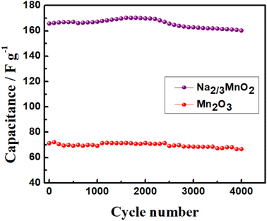 |
| | Fig. 7 Cycling stability of Na2/3MnO2 and Mn2O3 at a specific current of 2.0 A g−1 in the potential range of −0.2 to 1.2 V vs. SCE in an aqueous solution of 1.0 M Na2SO4. | |
3.1 Performance of Na2/3MnO2‖AC asymmetric capacitor
Considering the better capacitance properties of Na2/3MnO2 over Mn2O3, we tried to evaluate its performance in an asymmetric capacitor. In order to assemble an asymmetric capacitor with activated carbon (AC) as the negative electrode, the capacitance property of AC was evaluated in 1.0 M aqueous Na2SO4 electrolyte. The CVs of AC were recorded in various potential ranges, whereas the GCD of AC was measured in the potential range of 0–(−0.8 V) vs. SCE. AC shows a rectangular-shaped CV without any redox activity, indicating its ideal double-layer capacitive property (Fig. S1†). A SC of about 250 F g−1 was obtained from the GCD of AC at 0.5 A g−1 (Fig. S1(b)†). Thus, in the three-electrode cell with Pt as the auxiliary electrode, both Na2/3MnO2 and AC exhibited high specific capacitances of 234 and 250 F g−1, respectively, in the 1.0 M Na2SO4 electrolyte. However, in real two-electrode supercapacitors, AC is used as the negative electrode. Hence, we also performed the separate capacitance measurements of Na2/3MnO2 and AC using AC as the auxiliary and SCE as the reference electrode. The specific capacitances of Na2/3MnO2 and AC were found to be 80 and 60 F g−1, respectively, in the potential ranges of 0–1.2 V and 0–(−0.8) V vs. SCE (Fig. S2†). It should be noted that, while high specific capacitances are reported in the literature using three-electrode cells, the specific capacitances reported for the electrochemical supercapacitors are usually less. Of course, the SC of the supercapacitor device should be around (¼)th of the SC measured for the individual electrodes in three-electrode cells due to the series combination of both electrodes. The mass ratio of positive to negative electrode plays a significant factor in the evaluation of specific capacitance of an asymmetric capacitor. Wu et al. have studied the influence of this mass ratio on the performance of NiCo LDH‖ AC hybrid SC.62 Taking into account the SCs of Na2/3MnO2 and AC and the potential windows of individual electrodes, the mass ratio was fixed at 1![[thin space (1/6-em)]](https://www.rsc.org/images/entities/char_2009.gif) :
:![[thin space (1/6-em)]](https://www.rsc.org/images/entities/char_2009.gif) 1.4 by following the equation as reported earlier,63,64
1.4 by following the equation as reported earlier,63,64| | |
m+/m− = SC− × ΔE−/SC+ × ΔE+
| (3) |
The CVs were measured in different voltage ranges in order to get an appropriate voltage where it shows the capacitive property. A pair of redox peaks are clearly visible in the CVs, indicating the pseudocapacitive properties of the asymmetric supercapacitor, as shown in Fig. 8. It can be seen that the supercapacitor can be cycled to 2.0 V without any sharp oxidation peak at high voltages (Fig. 8). Asymmetric supercapacitors of MnO2‖AC and NaMnO2‖AC are already reported with working voltages of 2.0 V in aqueous electrolytes of Na2SO4.36,63 The GCD was carried out at 0.1 A g−1 in order to evaluate the SC of this assembled supercapacitor device, which is shown in Fig. 8c. There is a linear variation of voltage with time, which indicates the capacitance property of the asymmetric supercapacitor within 2.0 V. A SC of about 37.7 F g−1 was obtained at 0.1 A g−1 based on the total masses of Na2/3MnO2 and AC with an operational voltage of 2.0 V. The GCD was carried out at different specific currents (Fig. 8d) in order to evaluate its power characteristic. A SC of about 16 F g−1 was obtained at 4.0 A g−1, which indicates the high-power characteristic of this asymmetric supercapacitor.
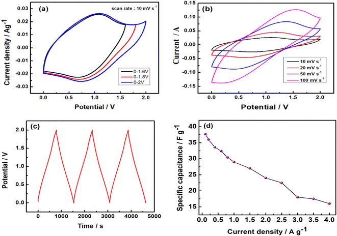 |
| | Fig. 8 (a) CVs of asymmetric Na2/3MnO2‖AC supercapacitor in different potential ranges, (b) CVs of the asymmetric supercapacitor at different scan rates, (c) galvanostatic charge–discharge cycles at a specific current of 0.1 A g−1, and (d) rate capability tests at different specific currents in an aqueous solution of 1.0 M Na2SO4. | |
The long-term cycling stability was performed by galvanostatic charge–discharge cycling at 0.8 A g−1 in 0–2.0 V. An initial SC of about 31.6 F g−1 was obtained, which increased to a value of 32.4 F g−1 during initial 1000 cycles and then stabilized even after 6000 cycles (Fig. 9). This result confirmed the long-term cycling stability of this asymmetric Na2/3MnO2‖AC supercapacitor. Thus, Na2/3MnO2‖AC can be a promising asymmetric supercapacitor considering the low cost and high abundance of Mn as well as Na.
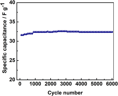 |
| | Fig. 9 Cycling stability of asymmetric Na2/3MnO2‖AC supercapacitor at 0.8 A g−1 in an aqueous solution of 1.0 M Na2SO4. | |
The electrochemical impedance spectra (EIS) of the asymmetric capacitor were measured at open circuit potential during cycling, which is shown in Fig. 10. A semicircle at the high-frequency region corresponding to the parallel combination of charge transfer resistance and double-layer capacitance, followed by a linear spike at low frequency was observed in the Nyquist plots.63 The intercepts at high frequency were found to be the same for the spectra measured after 1000 and 6000 cycles, indicating that the ohmic resistance (about 0.47 ohm) does not change upon cycling. Also, the charge transfer resistance (Rct) at the electrode/electrolyte interface indicated by the diameter of semicircles decreased slightly upon cycling, which can support the slight increase in the SC of the asymmetric supercapacitor with cycling.
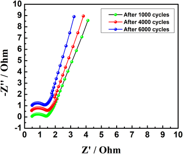 |
| | Fig. 10 Electrochemical impedance spectra (EIS) of asymmetric Na2/3MnO2‖AC supercapacitor measured at open circuit potential during extensive cycling in an aqueous solution of 1.0 M Na2SO4. | |
3.2 Calculation of energy and power density
Energy density and power density are the important characteristic features of a supercapacitor. The energy density (E) and power density (P) of this asymmetric capacitor were evaluated by using equations:| |
 | (4) |
| |
 | (5) |
where C is SC, V is the voltage and I is the charge–discharge current, plotted as Ragone plot in Fig. 11. An energy density of 20.9 W h kg−1 is obtained for this asymmetric supercapacitor, which is comparable with the reported energy density of 8–20 W h kg−1 for MnO2 and NaMnO2-based asymmetric supercapacitors.36,48,63,65 It should be noted that symmetric capacitors based on AC‖AC can provide an energy density of 5–6 W h kg−1 in aqueous electrolytes, because of low voltage. Thus, the asymmetric supercapacitor based on an aqueous electrolyte exhibits a higher energy density than the symmetric AC supercapacitors. A maximum power density of 4 kW kg−1 is achieved at the specific current of 4.0 A g−1.
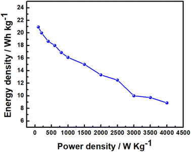 |
| | Fig. 11 Ragone plot of asymmetric Na2/3MnO2‖AC supercapacitor in an aqueous solution of 1.0 M Na2SO4. | |
4. Conclusions
In this study, P2-Na2/3MnO2 and Mn2O3 are synthesized by a hydrothermal method followed by annealing at 900 °C for 12 h. A SC of 234 F g−1 was obtained for Na2/3MnO2 whereas it was only 115 F g−1 for Mn2O3 when cycled at a specific current of 0.4 A g−1 in 1.0 M aqueous Na2SO4 electrolyte. The specific capacitance of the asymmetric Na2/3MnO2‖AC supercapacitor slightly increased from 31.6 to 32.4 F g−1 when cycled at a specific current of 0.8 A g−1 during initial 1000 cycles and then stabilized even after 6000 cycles within 2.0 V, indicating its remarkable cycling stability. The electrochemical impedance study indicated that the charge transfer resistance did not change significantly upon extensive cycling, thus supporting the cycling stability of the asymmetric Na2/3MnO2‖AC supercapacitor. Additionally, the asymmetric supercapacitor exhibited an energy density of 20.9 W h kg−1 and a power density of 4 kW kg−1. Thus, the asymmetric Na2/3MnO2‖AC supercapacitor can be very promising considering the low cost and environmental friendliness of Mn-based oxides as well as that of Na2SO4 electrolyte.
Author contributions
Aneesh Anand and P. K. Nayak conceptualized the work. Aneesh synthesized the sample and performed the experiments and wrote the original draft, which was reviewed and edited by P. K. Nayak.
Conflicts of interest
There are no conflicts of interest to declare.
Acknowledgements
The author Aneesh Anand thanks to the SRM Institute of Science and Technology (SRMIST) for providing the SRM Fellowship and all the research facilities, including SRM-SCIF for structural measurements. P. K. Nayak is grateful for the partial support within SRG funded by SERB, India.
References
- X. Zhao, Y. Zhang, Y. Yang and H. Wei, Batteries Supercaps, 2019, 2, 899–917 CrossRef CAS.
- H. B. Li, M. H. Yu, F. X. Wang, P. Liu, Y. Liang, J. Xiao, C. X. Wang, Y. X. Tong and G. W. Yang, Nat. Commun., 2013, 4, 1894–1989 CrossRef CAS PubMed.
- N. Hu, L. Huang, W. Gong and P. K. Shen, ACS Sustainable Chem. Eng., 2018, 6, 16933–16940 CrossRef CAS.
- K. Xu, J. Yang, S. Li, Q. Liu and J. Hu, Mater. Lett., 2017, 187, 129–132 CrossRef CAS.
- A. Ray, A. Roya, M. Ghosh, J. A. Ramos-Ramón, S. Saha, U. Pal, S. K. Bhattacharya and S. Das, Appl. Surf. Sci., 2019, 463, 513–525 CrossRef CAS.
- M. Winter and R. J. Brodd, Chem. Rev., 2004, 104, 4245–4269 CrossRef CAS PubMed.
- X. Zheng, L. Miao, Z. Song, W. Du, D. Zhu, Y. Lv, L. Li, L. Gan and M. Liu, J. Mater. Chem. A, 2022, 10, 611–621 RSC.
- Z. Song, L. Miao, L. Ruhlmann, Y. Lv, D. Zhu, L. Li, L. Gan and M. Liu, Adv. Funct. Mater., 2022, 32, 2208049–2208059 CrossRef CAS.
- L. Li, H. Hu and S. Ding, Inorg. Chem. Front., 2018, 5, 1714–1720 RSC.
- M. Dakshana, S. Meyvel, M. Malarvizhi, P. Sathya, R. Ramesh, S. Prabhu and M. Silambarasan, Vacuum, 2020, 174, 109218–109228 CrossRef CAS.
- Z. Liu, L. Zhang, G. Xu, L. Zhang, D. Jia and C. Zhang, RSC Adv., 2017, 7, 11129–11134 RSC.
- Q. Y. Li, Z. S. Li, L. Lina, X. Y. Wang, Y. F. Wang, C. H. Zhang and H. Q. Wang, Chem. Eng. J., 2010, 156, 500–504 CrossRef CAS.
- R. R. Rajagopal, L. S. Aravinda, R. Rajarao, B. R. Bhat and V. Sahajwalla, Electrochim. Acta, 2016, 211, 488–498 CrossRef CAS.
- J. P. Zheng, P. J. Cygan and T. R. Jow, J. Electrochem. Soc., 1995, 142, 2699–2703 CrossRef CAS.
- Y. Liu, W. Zhao and X. Zhang, Electrochim. Acta, 2008, 53, 3296–3304 CrossRef CAS.
- R. Warren, F. Sammoura, F. Tounsi, M. Sanghadasa and L. Lin, J. Mater. Chem. A, 2015, 3, 15568–15575 RSC.
- J. Zhang, J. Ma, L. L. Zhang, P. Guo, J. Jiang and X. S. Zhao, J. Phys. Chem. C, 2010, 114, 13608–13613 CrossRef CAS.
- S. D. Dhas, P. S. Maldar, M. D. Patil, A. B. Nagare, M. R. Waikar, R. G. Sonkawade and A. V. Moholkar, Vacuum, 2020, 181, 109646–109654 CrossRef CAS.
- H. Xiao, S. Yao, H. Liu, F. Qu, X. Zhang and X. Wu, Prog. Nat. Sci.: Mater. Int., 2016, 26, 271–275 CrossRef CAS.
- P. K. Nayak and N. Munichandraiah, Mater. Sci. Eng., B, 2012, 177, 849–854 CrossRef CAS.
- M. Yang, K. Li and L. Xiao, Mater. Sci. Eng., B, 2021, 269, 115173–115179 CrossRef CAS.
- H. B. Li, M. H. Yu, F. X. Wang, P. Liu, Y. Liang, J. Xiao, C. X. Wang, Y. X. Tong and G. W. Yang, Nat. Commun., 2013, 4, 1894–1900 CrossRef CAS PubMed.
- X. Xiong, D. Ding, D. Chen, G. Waller, Z. Wang and M. Liu, Nano Energy, 2015, 11, 154–161 CrossRef CAS.
- T. E. Kibona, J. Solid State Electrochem., 2020, 42, 1587–1598 CrossRef.
- X. Liu, S. Shi, Q. Xiong, L. Li, Y. Zhang, H. Tang, C. Gu, X. Wang and J. Tu, ACS Appl. Mater. Interfaces, 2013, 5, 8790–8795 CrossRef CAS PubMed.
- T. Munawar, M. Shahid, N. Faisal, M. Sumaira, M. Muhammad, N. Ashiq and F. Iqbal, Mater. Sci. Eng., B, 2022, 284, 115900–115911 CrossRef CAS.
- M. A. Yewale, R. A. Kadam, N. K. Kaushik, J. R. Koduru, N. B. Velhal, U. T. Nakate, A. A. Jadhavar, N. D. Sali and D. K. Shin, Mater. Sci. Eng., B, 2023, 287, 116072–116083 CrossRef CAS.
- A. Cherusseri, N. Choudhary, K. S. Kumar, Y. Jung and J. Thomas, Nanoscale Horiz., 2019, 4, 840–858 RSC.
- M. Abuali, N. Arsalani, I. Ahadzadeh and T. Nann, Mater. Sci. Eng., B, 2022, 276, 115578–115590 CrossRef CAS.
- P. Yang, L. Feng, J. Hu, W. Ling, S. Wang, J. Shi, Z. Yang and F. Wang, ChemElectroChem, 2019, 6, 1–9 CrossRef.
- M. Barazandeh and S. H. Kazemi, Sci. Rep., 2022, 12, 4628–4640 CrossRef CAS PubMed.
- T. Xiong, W. Siang, V. Lee and J. Xue, ACS Appl. Energy Mater., 2018, 1, 5619–5626 CAS.
- N. Jabeen, A. Hussain, Q. Xia, S. Sun, J. Zhu and H. Xia, Adv. Mater., 2017, 29, 1700804–1700812 CrossRef PubMed.
- N. Karikalan, C. Karuppiah, S. Chen, M. Velmurugan and P. Gnanaprakasam, Chem. - Eur. J., 2017, 23, 2379–2386 CrossRef CAS PubMed.
- B. H. Zhang, Y. Liu, Z. Chang, Y. Q. Yang, Z. B. Wen, Y. P. Wu and R. Holze, J. Power Sources, 2014, 253, 98–103 CrossRef CAS.
- Q. T. Qu, Y. Shi, S. Tian, Y. H. Chen, Y. P. Wu and R. Holze, J. Power Sources, 2009, 194, 1222–1225 CrossRef CAS.
- V. Subramanian, H. Zhu, R. Vajtai, P. M. Ajayan and B. Wei, J. Phys. Chem. B, 2005, 109, 20207–20214 CrossRef CAS PubMed.
- P. K. Nayak and N. Munichandraiah, Microporous Mesoporous Mater., 2011, 143, 206–214 CrossRef CAS.
- Y. Li, H. Xie, J. Wang and L. Chen, Mater. Lett., 2011, 65, 403–405 CrossRef CAS.
- T. Cottineau, M. Toupin, T. Delahaye, T. Brousse and D. Belanger, Appl. Phys. A, 2006, 82, 599–606 CrossRef CAS.
- M.-S. Wu, Appl. Phys. Lett., 2005, 87, 153102–153104 CrossRef.
- C. Wei, H. Pang, B. Zhang, Q. Lu, S. Liang and F. Gao, Sci. Rep., 2013, 3, 2193–2197 CrossRef PubMed.
- J. R. Choi, J. Lee, G. Yang, Y. J. Heo and S. J. Park, Catalysts, 2020, 10, 256–265 CrossRef CAS.
- P. Murovhi, D. J. Tarimo, K. O. Oyedotun and N. Manyala, J. Energy Storage, 2020, 32, 101797–101807 CrossRef.
- Z. Fan, J. Ren, F. Zhang, T. Gu, S. Zhang, R. P. Ren and Y. K. Lv, J. Mater. Sci., 2022, 57, 1281–1290 CrossRef CAS.
- Q. Z. Zhang, D. Zhang, Z. C. Miao, X. L. Zhang and S. L. Chou, Small, 2018, 14, 1702883–1702897 CrossRef PubMed.
- M. S. Hong, S. H Lee and S. W. Kim, Solid State Lett., 2002, 5, A227–A230 CrossRef CAS.
- S. Xu, T. Wan, K. Zhou, G. Zhu, Z. He, H. Huang, T. Zhou, W. Mao, J. Wu, S. Gong and Y. Qiao, Mater. Res. Express, 2020, 7, 035508–035526 CrossRef CAS.
- X. Wang, W. S. Liu, X. Lu and P. S. Lee, J. Mater. Chem., 2012, 22, 23114–23119 RSC.
- J. Zhang, F. Liu, J. P. Cheng and X. B. Zhang, ACS Appl. Mater. Interfaces, 2015, 7, 17630–17640 CrossRef CAS PubMed.
- G. Godillot, P.-L. Taberna, B. Daffos, P. Simon, C. Delmas, L. G. Demourgues and G. Godillot, J. Power Sources, 2016, 331, 277–284 CrossRef CAS.
- S. Pappu, K. Nanaji, S. Mandati, T. N. Rao, S. K. Martha and S. V. Bulusu, Batteries Supercaps, 2020, 3, 1209–1219 CrossRef CAS.
- A. Konarov, H. J. Kim, N. Voronina, Z. Bakenov and S. T. Myung, ACS Appl. Mater. Interfaces, 2019, 11, 28928–28933 CrossRef CAS PubMed.
- Z. Zhou, J. Li, Z. Luo, Z. He, J. Zheng, Y. Li, J. Mao, K. Dai, C. Yan and Z. Sun, Ionics, 2021, 27, 5187–5196 CrossRef CAS.
- S. Kumakura, Y. Tahara, S. Sato, K. Kubota and S. Komaba, Chem. Mater., 2017, 29, 8958–8962 CrossRef CAS.
- S. Kumakura, Y. Tahara, K. Kubota, K. Chihara and S. Komaba, Angew. Chem., 2016, 128, 12952–12955 CrossRef.
- C. Ke, F. Fu, J. Zheng and W. Yang, Ionics, 2019, 26, 727–734 CrossRef.
- P. K. Nayak, L. Yang, K. Pollok, F. Langenhorst, L. Wondraczek and P. Adelhelm, Batteries Supercaps, 2019, 2, 104–111 CrossRef CAS.
- N. S. Neghmouche and T. Lanez, Recent Trends in Physical Chem.: An International J, 2013, 1, 1–3 Search PubMed.
- W. Li, J. Shao, Q. Liu, X. Liu, X. Zhou and J. Hu, Electrochim. Acta, 2015, 157, 108–114 CrossRef CAS.
- P. K. Nayak and N. Munichandraiah, J. Solid State Electrochem., 2012, 16, 2739–2749 CrossRef CAS.
- Q. Qin, D. Ou, C. Ye, L. Chen, B. Lan, J. Yan and Y. Wu, Electrochim. Acta, 2019, 305, 403–415 CrossRef CAS.
- V. Khomenko, E. R. Piñero and F. Béguin, J. Power Sources, 2006, 153, 183–190 CrossRef CAS.
- R. Mohanty, G. Swain, K. Parida and K. Parida, J. Alloys Compd., 2022, 919, 165753–165765 CrossRef CAS.
- T. Cottineau, M. Toupin, T. Delahaye, T. Brousse and D. Belanger, Appl. Phys. A, 2006, 82, 599–606 CrossRef CAS.
|
| This journal is © The Royal Society of Chemistry 2023 |
Click here to see how this site uses Cookies. View our privacy policy here.  Open Access Article
 *
*
![[thin space (1/6-em)]](https://www.rsc.org/images/entities/char_2009.gif) :
:![[thin space (1/6-em)]](https://www.rsc.org/images/entities/char_2009.gif) 10
10![[thin space (1/6-em)]](https://www.rsc.org/images/entities/char_2009.gif) :
:![[thin space (1/6-em)]](https://www.rsc.org/images/entities/char_2009.gif) 10 by wt%. Electrodes were prepared by repeated brush coating onto graphite foil current collectors (0.30 μm thick) and drying to get the desired mass. The electrodes were finally dried at 100 °C for 6 h in a vacuum oven before assembling for their electrochemical testing. The electrode area was 1.0 cm2 and the loading of the active mass was 1.0 mg cm−2. The cyclic voltammetry (CV) and galvanostatic charge–discharge (GCD) tests of individual electrodes were performed using a three-electrode cell using Pt foil and saturated calomel electrode (SCE) as counter and reference electrodes, respectively, in an aqueous solution of 1.0 M Na2SO4. The experimental results such as the specific capacitance of the Na2/3MnO2 and Mn2O3 are reported here after performing the experiments for at least 2–3 times. The experimental error is within 2–4%. The asymmetric Na2/3MnO2‖AC supercapacitor was assembled using 4 cm × 4 cm electrodes with a commercial cellulose acetate membrane as the separator and tested in a two-electrode cell using an aqueous electrolyte solution of 1.0 M Na2SO4. The electrochemical impedance spectra (EIS) were measured at open circuit potential (OCP) with an AC amplitude of 10 mV in the frequency range of 10 kHz to 0.01 Hz using ZIVE SP1 potentiostat/galvanostat.
10 by wt%. Electrodes were prepared by repeated brush coating onto graphite foil current collectors (0.30 μm thick) and drying to get the desired mass. The electrodes were finally dried at 100 °C for 6 h in a vacuum oven before assembling for their electrochemical testing. The electrode area was 1.0 cm2 and the loading of the active mass was 1.0 mg cm−2. The cyclic voltammetry (CV) and galvanostatic charge–discharge (GCD) tests of individual electrodes were performed using a three-electrode cell using Pt foil and saturated calomel electrode (SCE) as counter and reference electrodes, respectively, in an aqueous solution of 1.0 M Na2SO4. The experimental results such as the specific capacitance of the Na2/3MnO2 and Mn2O3 are reported here after performing the experiments for at least 2–3 times. The experimental error is within 2–4%. The asymmetric Na2/3MnO2‖AC supercapacitor was assembled using 4 cm × 4 cm electrodes with a commercial cellulose acetate membrane as the separator and tested in a two-electrode cell using an aqueous electrolyte solution of 1.0 M Na2SO4. The electrochemical impedance spectra (EIS) were measured at open circuit potential (OCP) with an AC amplitude of 10 mV in the frequency range of 10 kHz to 0.01 Hz using ZIVE SP1 potentiostat/galvanostat.


![[thin space (1/6-em)]](https://www.rsc.org/images/entities/char_2009.gif) :
:![[thin space (1/6-em)]](https://www.rsc.org/images/entities/char_2009.gif) 1.4 by following the equation as reported earlier,63,64
1.4 by following the equation as reported earlier,63,64


