DOI:
10.1039/D3RA01136D
(Paper)
RSC Adv., 2023,
13, 10577-10591
A molybdenum disulfide/nickel ferrite-modified voltammetric sensing platform for ultra-sensitive determination of clenbuterol under the presence of an external magnetic field†
Received
20th February 2023
, Accepted 28th March 2023
First published on 3rd April 2023
Abstract
The electrochemical behavior and sensing performance of an electrode modified with NiFe2O4 (NFO), MoS2, and MoS2–NFO were thoroughly investigated using CV, EIS, DPV, and CA measurements, respectively. MoS2–NFO/SPE provided a higher sensing performance towards the detection of clenbuterol (CLB) than other proposed electrodes. After optimization of pH and accumulation time, the current response recorded at MoS2–NFO/SPE linearly increased with an increase of CLB concentration in the range from 1 to 50 μM, corresponding to a LOD of 0.471 μM. In the presence of an external magnetic field, there were positive impacts not only on mass transfer, ionic/charge diffusion, and absorption capacity but also on the electrocatalytic ability for redox reactions of CLB. As a result, the linear range was widened to 0.5–50 μM and the LOD value was about 0.161 μM. Furthermore, stability, repeatability, and selectivity were assessed, emphasizing their high practical applicability.
1. Introduction
Recent years have seen renewed interest in spinel ferrite materials (MFe2O4) due to their unique physical and chemical properties, for example, good biocompatibility, high chemical stability, diversity of redox states, low cost, and unique magnetic properties.1–8 Here, NiFe2O4 (NFO) is a special member of the spinel ferrite family (MFe2O4–M = Co2+, Mn2+, Ni2+, and Zn2+) with an inverse spinel structure, in a bulk state. Fe3+ ions occupy the tetrahedral sites, while the octahedral sites are shared by Fe3+ and Ni2+ ions.3 Previous studies pointed out that the surface, size, crystallinity, morphology, and composition strongly correlate with the physicochemical properties of spinel ferrite materials.9–13 Moreover, these properties are influenced by some advanced parameters such as dimension, dispersion, and surface area which can be changed by combining with various nanomaterials.13–17
For the aim of enhancing the inherent characteristics, many spinel ferrite-based nanocomposites have been fabricated for boosting their diversity applicability from environmental, biomedical, and sensors to biotechnology applications.18–21 Among them, MoS2/NFO has been considered a highly promising nanocomposite for many different applications. Benefiting from possessing a large surface area and impressive structure with three atomic layers S–Mo–S stacked by van der Waals forces, MoS2 layers could support the effective dispersion of NFO nanoparticles (NFO NPs).22–24 Besides, owing to the presence of two different components within a structure, NFO NPs remarkably prevented the aggregation of MoS2 layers, leading to better connections and interactions between MoS2 and NFO as well as creating a larger active surface area. Accordingly, MoS2–NFO has been used as a potential candidate for electrochemical supercapacitors, catalysis, and energy conversion applications.25 For instance, M. Karpuraranjith et al.26 reported MoS2–NFO as an efficient dual-functional hybrid catalyst for the oxygen evolution reaction and degradation of dye pollutants. Yan Zhao et al.27 also developed NFO–MoS2 composites with great synergistic effects, which offered a higher-performance supercapacitor, compared with that of individual MoS2 sheets and NFO NPs, respectively. In another research, Wenzhi Fu et al.28 demonstrated the enhanced visible-light photocatalytic activities in the NFO–MoS2 structure.
However, as far as we know, the greater insight into the electrochemical characteristics and sensing performance of NFO–MoS2-modified electrodes has been not still explored while it is one of the essential goals in opening new opportunities for novel applications of not only NFO–MoS2 but also spinel ferrite-based nanomaterials. As known, NFO–MoS2 nanocomposites possess many advantages, which are very beneficial for electron transfer reactions, electrochemical behaviors, and electrocatalytic activities including large active surface area, high electronic conductivity, good redox chemistry, and potential electrocatalytic. Such merits promise to provide outstanding electrochemical properties and performance for NFO–MoS2-modified electrodes. In this work, NFO, MoS2, and MoS2–NFO nanocomposites were prepared using simple methods including hydrothermal and probe sonication methods, aiming to modify the working electrode surface of commercial screen-printed electrodes (SPEs). The electrochemical characteristics and sensing performance towards clenbuterol (CLB) detection of the proposed electrodes were thoroughly investigated. Among modified SPEs, MoS2–NFO (2![[thin space (1/6-em)]](https://www.rsc.org/images/entities/char_2009.gif) :1)/SPE exhibited impressive electrochemical properties and sensing performance compared with other modified electrodes. Particularly, as demonstrated in our previous reports, the positive effect of the presence of the external magnetic fields on electrochemical behaviors and sensing performance was demonstrated.29–32 Herein, the influence of external magnetic field (MF) on the MoS2–NFO (2:1)/SPE was also further evaluated, contributing to optimizing the new research in the future.
:1)/SPE exhibited impressive electrochemical properties and sensing performance compared with other modified electrodes. Particularly, as demonstrated in our previous reports, the positive effect of the presence of the external magnetic fields on electrochemical behaviors and sensing performance was demonstrated.29–32 Herein, the influence of external magnetic field (MF) on the MoS2–NFO (2:1)/SPE was also further evaluated, contributing to optimizing the new research in the future.
2. Experimental section
2.1. Chemicals
All chemicals were reagent grade and used as received: sodium hydroxide (NaOH >98%), polyvinylpyrrolidone (PVP), NiCl2, and FeCl3·6H2O were obtained from Xilong Scientific Co., Ltd. (China) and Guangdong Guanghua Sci-Tech. Co., Ltd. K3(Fe(CN)6), K4(Fe(CN)6)·3H2O, clenbuterol (CLB), and molybdenum(IV) sulfide (MoS2) (98%, <2 μm) were purchased from Sigma-Aldrich (USA). Phosphate buffer saline (PBS, pH 7.4) was employed as a supporting electrolyte and was prepared from NaCl, KCl, Na2HPO4, and KH2PO4. Further, the pH of the buffer solution was adjusted by H3PO4 and NaOH solutions. The carbon screen-printed electrode (SPE) was provided by DS Dropsens, Spain. The dimensions of SPE are 3.4 × 1.0 × 0.05 cm (L × W × T). The structure of SPE consists on:
+ Working electrode: carbon (4 mm diameter).
+ Auxiliary electrode: carbon.
+ Reference electrode: silver or Ag/AgCl.
2.2. Methods
2.2.1 Preparation of NiFe2O4 nanoparticles. By using the hydrothermal method and the following annealing treatment, NiFe2O4 nanoparticles (NFO NPs) were prepared.6,7,14 Firstly, dissolved solutions of 0.3 M NiCl2 and 0.3 M FeCl3 were mixed under magnetic stirring for 30 min. Secondly, 200 mmol of 0.2 M NaOH was added into the solution until pH reached 9. The solution was continuously stirred for 1 h to produce a homogeneous solution. Then, this homogeneous solution was put into a hydrothermal autoclave reactor and heated at temperature T = 180 °C with a holding time of 20 h. After heating, the precipitation was filtered and washed several times with alcohol and dried for 6 h at T = 80 °C in air, and labelled as NFO samples.
2.2.2 Preparation of MoS2 sheets. Firstly, 3 mg polyvinylpyrrolidone (PVP) and 10 mg powder of molybdenum sulfide (MoS2) were put into 100 mL distilled water and stirred for 30 min. Secondly, the mix solution was ultrasonicated for 1 h by an UWave 2000 instrument under a power of 560 W.
2.2.3 Preparation of MoS2–NFO nanocomposites. 1 mg NFO NPs was stirred in 10 mL distilled water for 30 min, then added the MoS2 solution with various ratios of 1:1 and 1:2. Finally, the above-mixed solutions were ultrasonicated for 20 min.
2.2.4 Preparation of NFO/SPE, MoS2/SPE and MoS2–NFO/SPE. To study the electrochemical behaviors of electrodes modified with MoS2, NFO, and MoS2–NFO, screen-printed electrodes (SPE) were modified with proposed materials. The modified SPEs were prepared by dropping homogeneous solutions of MoS2, NFO, and MoS2–NFO, respectively, with a concentration of 1 mg mL−1 as follows steps: step one, adding 5 mg of proposed materials into 5 mL distilled water and sonicating for 30 min to get homogeneous solutions; step two, dropping these homogeneous solutions on the working electrode surface of bare SPE and drying at 45 °C. After that, MoS2/SPE, NFO/SPE, and MoS2–NFO/SPE were dried in air for the following electrochemical measurements.
2.3. Apparatus
2.3.1 Physical measurements: XRD, Raman, VSM, and SEM. In this study, the scanning electron microscopy (SEM) was used to observe the morphology, size, as well as distribution of the prepared samples. By using Bruker D5005 X-ray diffractometer attached Cu Ka radiation (λ = 0.154056 nm), the crystalline structure was analyzed to obtain the parameters and crystallographic phase of MoS2 and NFO. Raman spectroscopy (Horiba MacroRAM™) with 785 nm laser excitation was also employed to study physicochemical characteristics. Additionally, the magnetic characteristics of the proposed materials were determined using a vibrating sample magnetometer (VSM, EV9, MicroSense) at room temperature.
2.3.2 Evaluation of electrochemical characterizations. The electrochemical characteristics of bare SPE and modified SPEs including NFO/SPE, MoS2/SPE, and MoS2–NFO/SPE, were performed on a Palmsens 4 electrochemical workstation (PS Trace-Netherlands), a three-electrode system, at a temperature around 298 K, by measuring cyclic voltammetry (CV), differential pulse voltammetry (DPV), and electrochemical impedance spectroscopy (EIS) measurement at various setup conditions. First of all, the synthesized samples were tested by cyclic voltammetry (CV) measurements in the potential range from −0.3 to 0.6 V at different scan rates from 20 to 70 mV s−1 in 0.1 M KCl solution containing 2.5 and 5 mM K3[Fe(CN)6]/K4[Fe(CN)6], as a redox probe. As soon after CV measurement, in the range of frequency 0.01 to 50000 Hz, all electrodes were continually executed by electrochemical impedance spectroscopy (EIS) measurement.The second, CV and DPV were measured on the bare SPE and modified SPE in the presence of CLB without and with MF. CV measurements were performed at a scan rate of 70 mV s−1 in the potential range from −0.3 to 0.6 V, potential step = 0.01 V. Meanwhile, DPV measurements were also carried out as following conditions: scan rate of 6 mV s−1, Epulse = 0.075 V, Tpulse = 0.25 s, Tequilibrium = 120–200 s and pH difference.
3. Results and discussion
3.1. Microstructure and physical characterizations
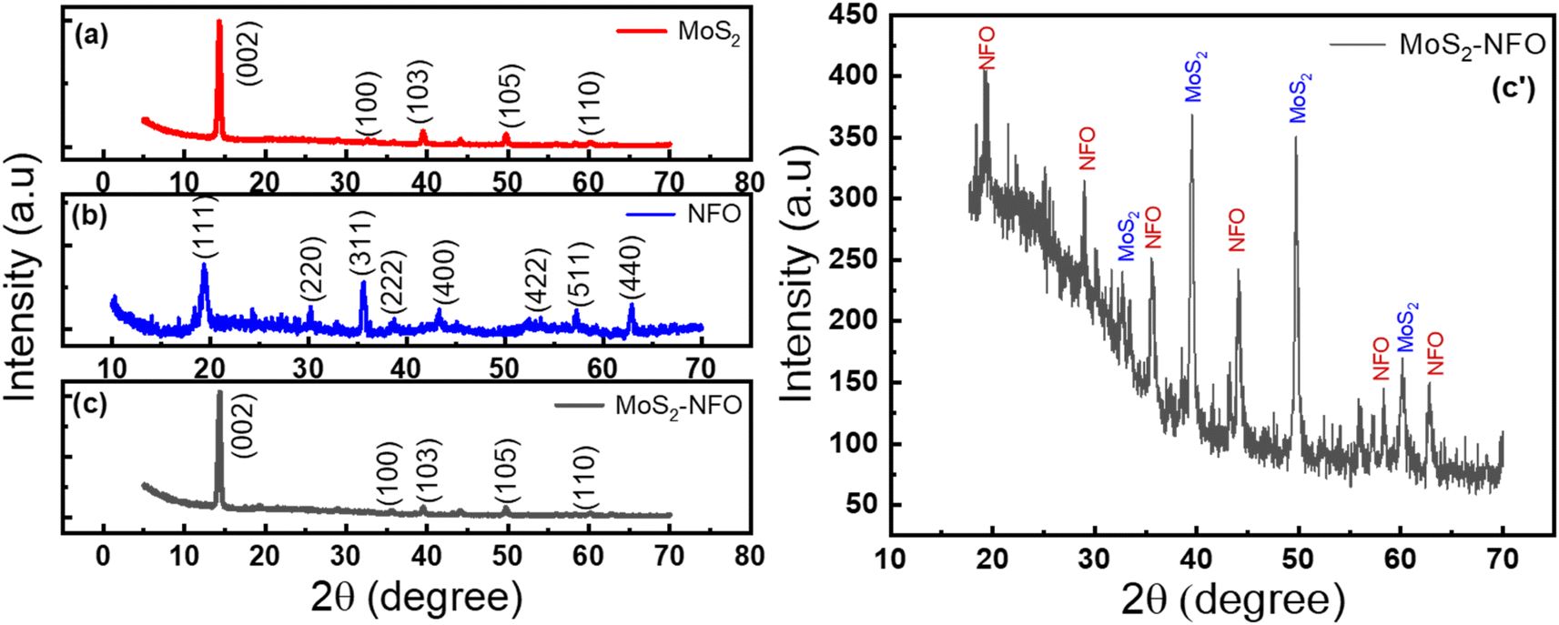
Powder XRD diffraction of NFO, MoS2, and MoS2–NFO material was collected in the range of 2θ from 5° to 70°, as shown in Fig. 1. The patterns of MoS2 presented peaks at 14.3°, 32.7°, 39.5°, 49.7°, and 60.07°, matching the planes of (002), (100), (103), (105), and (110) – (no. 01-075-1539 in ICDD card).33 Fig. 1b has eight characteristic peaks of the NFO NPs with planes of (111), (220), (311), (222), (400), (422), (511), and (440), respectively – ICDD card no. 54-0964.34 The size of NFO NPs was determined at about 123.72 nm by equation Scherrer's formula d = kSλCu/βcosθ, with kS as Scherrer constant and β is full width at half maximum of peak 2θ = 19.5° (Fig. S1d†). The XRD pattern of MoS2–NFO nanocomposites was recognized in Fig. 1c and zoomed in Fig. 1c′, one can see two well-defined broad peaks at 39.5° and 49.7°, belonging to (103) and (105) planes of MoS2. Meanwhile, the presence of other low peaks could be featured in XRD diffraction of NFO NPs within MoS2–NFO nanocomposites, indicating the co-existence of both MoS2 sheets and NFO NPs within the MoS2–NFO nanocomposites. More importantly, the effective combination between NFO NPs and MoS2 did not cause any change in the crystal structure of components.
 |
| | Fig. 1 (a–c) XRD spectrum of NFO, MoS2, MoS2–NFO and (c′) the zoomed image of MoS2–NFO, respectively. | |
Fig. 2 illustrates SEM images of NFO NPs, MoS2 sheets, and MoS2–NFO nanocomposites. As can be seen from Fig. 2a, the morphology of the NFO sample displayed nanoparticles with hexagonal plate-like morphology and uniform small size. By using ImageJ software, the size of NFO was accurately estimated to be 125 nm. In Fig. 2b, it is obvious that the MoS2 sample was composed of two-dimensional ultrathin sheets, distributed randomly with around 1.15 μm dimension. For the MoS2–NFO nanocomposites sample, it can see the small NFO NPs were dispersedly interlaced on the MoS2 sheets by forming heterojunctions, indicating NFO and MoS2 were completely combined with each other with slight aggregation due to the strong magnetism of NFO NPs. By stacking NFO-NPs among 2D-MoS2 materials through non-covalent van der Waals interactions, it displays the metallic–metallic contact without any other chemical bonds. It is suggested that the metallic nuclei in NFO with a strong affinity towards valency-deficient S atoms were preferentially anchored to the edges and defects of the MoS2 nanosheets, where S atoms act as sites for metal nuclei seeding, leading to the uniform distribution of NFO-NPs on MoS2 materials.24,35,36
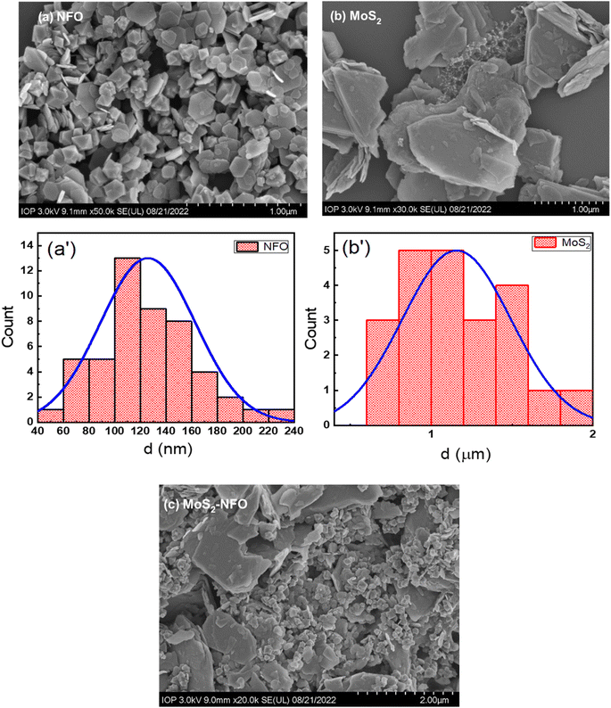 |
| | Fig. 2 (a–c) SEM images of the as-synthesized materials (NFO, MoS2, and MoS2–NFO); (a′ and b′) size distribution of NFO and MoS2 samples. | |
The Raman spectra of all synthesized samples (NFO, MoS2, and MoS2–NFO) were shown in Fig. S1.† It is evident to see NFO spectrum has 4 bands at 335, 486, 571, and 703 cm−1, as described in Fig. S1a,† matched well with earlier published reports.37,38 Fig. S1b† exhibited two characteristic peaks of MoS2 at 385 and 409 cm−1. These peaks were attributed due to the in-plane (E12g) and the out-of-plane (A1g) vibration modes, respectively. The difference between these two peaks of 24 cm−1, suggesting that the sample MoS2 has a few layers.25,39–41 For MoS2–NFO nanocomposites, the presence of characteristic peaks of both MoS2 and NFO was recorded, demonstrating the co-existence of MoS2 and NFO within the nanocomposite structure (Fig. S1c†), which is consistent with the XRD results observed.
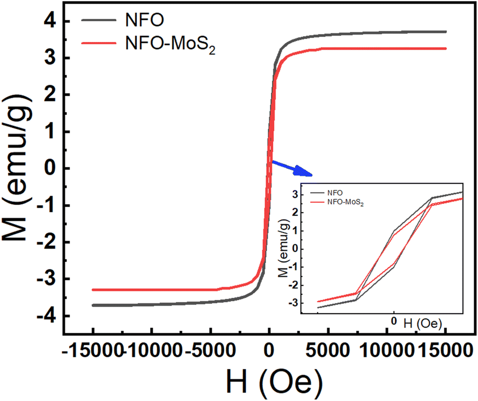
The magnetic characteristics of synthesized samples were observed via the magnetic hysteresis (M–H) curves at room temperature. The hysteresis loops were described in Fig. 3, the value of saturation magnetization (Ms) was determined around 37.2 emu g−1 for NFO and 28.8 emu g−1 MoS2–NFO samples, while the MoS2 sample did not show a magnetic curve. The considerable decrease in Ms value when NFO NPs were combined with MoS2, is consistent with the weak magnetic properties of MoS2 sheets originating from the existence of zigzag edges within layered structure. Similarly, the Mr and the coercivity (Hc) values of these proposed samples were determined approximately 9.94 emu g−1 and 131.18 Oe for NFO, 8.6 emu g−1 and 140.79 Oe for MoS2–NFO samples, respectively. Although, the increase of magnetic property at MoS2–NFO sample was observed, it still guarantees the good magnetic response when the external magnetic field (MF) applied.
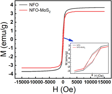 |
| | Fig. 3 Magnetization curves of NFO and MoS2–NFO samples. | |
3.2. Electrochemical investigations
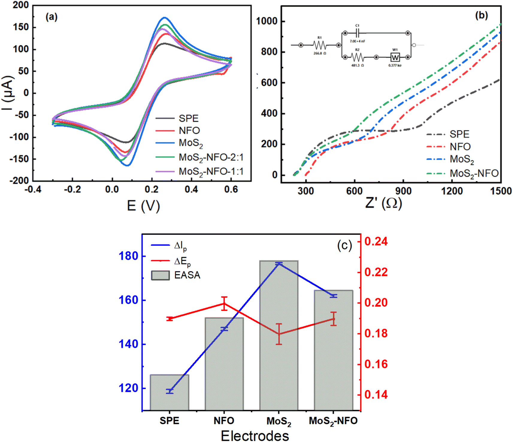
In the first step to investigate electrochemical characterizations of proposed electrodes, CV measurements were carried out in 0.1 M KCl solution containing 5.0 mM [Fe(CN)6]3−/4− at a scan rate of 50 mV s−1. As can see in Fig. 4a, all recorded CV curves showed a pair of significant reversible redox peaks appeared at 0.1 V and 0.3 V, which are attributed due to the electron transfer reaction of [Fe(CN)6]4− reversibly into [Fe(CN)6]3− and at the same time [Fe(CN)6]3− reversibly into [Fe(CN)6]2−. However, the remarkable difference in current response intensity at each electrode needs to be stressed. In this case, the higher current intensity was observed at the MoS2/SPE (176 μA), MoS2–NFO (2:1)/SPE (160 μA), and MoS2–NFO (1:1)/SPE (155 μA) than that of bare SPE (116 μA) and even NFO/SPE (146 μA). To explain this, some kinetic parameters involving the electron transfer reaction of the redox probes were calculated and evaluated in detail. Namely, the peak-to-peak separation potential (ΔEp = Epa − Epc) from CV curves, a critical proof, reflects the limitation in electrical conductivity and charge transfer kinetics. It was determined in the order: MoS2/SPE < MoS2–NFO (2:1)/SPE < MoS2–NFO (1:1)/SPE < NFO/SPE, which is much lower than that of bare SPE for a single electron-transfer process. Clearly, the modification of the electrode surface brought out many positive improvements in conductivity and charge transfer, compared with bare SPE. Furthermore, when CV measurements were performed at various scan rates in the range from 20 to 70 mV s−1 on the proposed electrodes, the changes in response current intensity and the reversible redox peak potential were observed at all modified electrodes even in the bare SPE (Fig. S2†). In this case, the current response linearly increased in the increase of square root of the scan rate (ν1/2), corresponding to the regression equations:
| Ip = 16.92ν1/2 (mV s−1) + 27.633 (R2 = 0.999) for NFO/SPE |
| Ip = 23.01ν1/2 (mV s−1) + 13.094 (R2 = 0.999) for MoS2/SPE |
| Ip = 19.63ν1/2 (mV s−1) + 22.269 (R2 = 0.999) for MoS2–NFO (2:1)/SPE |
| Ip = 20.44ν1/2 (mV s−1) + 17.227 (R2 = 0.999) for MoS2–NFO (1:1)/SPE |
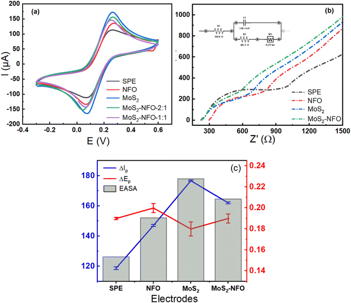 |
| | Fig. 4 (a and b) CV profiles and EIS plots of bare SPE and SPEs modified with NFO, MoS2, MoS2–NFO (2:1), and MoS2–NFO (1:1); (c) the obtained values of I and AESA recorded on various electrodes in 0.1 M KCl solution containing 5.0 mM [Fe(CN)6]3−/4−. | |
From that, the electrochemical active surface area (EASA or A) was calculated using the Randles–Sevcik equation (25 °C) as described by equation:7,23,42,43
| Ip = (2.69 × 10⁵)n3/2D1/2Aν1/2C |
where
n stands for the number of the electron in a redox reaction,
D represents the diffusion coefficient of 7.6 × 10
−6 cm
2 s
−1,
A refers to the electrochemical active electrode surface area (cm
2),
C indicates the bulk concentration of [Fe(CN)
6]
3−/4−. According to that, the value of EASA was calculated at about 0.153 cm
2 for bare SPE, 0.191 cm
2 for NFO/SPE, 0.229 cm
2 for MoS
2/NFO, 0.202 cm
2 for MoS
2–NFO (1
:
1)/SPE, and 0.209 cm
2 for MoS
2–NFO (2
:
1)/SPE, respectively. As can see, the highest value of EASA and the lowest value of separation potential (Δ
Ep) were achieved at MoS
2/SPE, it is in accordance with the highest value of current intensity at this electrode. This result might be since the fact that MoS
2 sheets have a much larger surface area and higher electrical conductivity than NFO NPs, which facilitates an effective raise of the electron transfer and interaction in the middle of the probe molecules with the electrode surface. Further to mention, the good combination at a weight ratio of 1
:
2 between NFO and MoS
2 also brought excellent enhancements for EASA and Δ
Ep values. As indicated in SEM images, NFO NPs were uniformly distributed onto MoS
2 sheets, leading to effectively inhibiting the self-aggregation of NFO NPs and MoS
2 sheets. This is beneficial for the exposure of active sites and therefore improving the conductivity and electron transfer. Additionally, the close contact between NFO NPs and MoS
2 sheets suggested a strong interaction was generated at their interface. However, it needs to be noted that, at the higher weight ratio of NFO within MoS
2–NFO (1
:
1) nanocomposites, the values of peak current recorded seem to have a decreasing trend, compared with that of the MoS
2–NFO (2
:
1) sample. This could be followed by the excess increase of NFO NPs led to agglomeration and break of the structure of MoS
2 sheets into smaller pieces. Consistency of these proposes with the values of EASA and separation potential (Δ
Ep) was found.
To further verify the great improvement of electrical conductivity and charge transfer kinetics arising from the modification of the electrode surface with proposed synthetic samples, electrochemical impedance spectroscopy (EIS) is considered the effective direct method to evaluate charge transfer ability onto the electrode surface.44 Fig. 4b shows Nyquist diagrams of various electrodes in a mixture solution of 0.1 M KCl solution containing 5.0 mM [Fe(CN)6]3−/4−, which confirms the difference in the electron transfer process occurring at each different electrode. In which, the electron transfer resistance (Rct) value is one of the most parameters controlling the kinetics of the electron transfer reactions of the redox probes at the electrode/electrolyte interface. This value is directly determined via the semicircle diameter in the high-frequency range. As seen, the Rct value could be estimated as approximately 487.3, 242.8, 180.9, 214.5, and 200.6 Ω for bare SPE, NFO/SPE, MoS2/SPE, MoS2–NFO (1:1)/SPE, and MoS2–NFO (2:1)/SPE, respectively. It is interesting to see that the obtained results fitted well with the CV response and separation potential (ΔEp) of all electrodes recorded. Worthy of note, the Rct value was employed to estimate the standard heterogeneous rate constant (ket) for all electrodes:23,29,45
here
R,
T, and
F are used with their usual meaning,
A donates electrochemical active area (cm
2),
Co refers to the bulk concentration of [Fe(CN)
6]
3−/4−,
Rct implies the electron transfer resistance (Ω). The
ket value was found for the bare SPE, NFO/SPE, MoS
2/NFO, MoS
2–NFO (1
:
1)/SPE, and MoS
2–NFO (2
:
1)/SPE to be around 7.1 × 10
−4, 1.15 × 10
−3, 1.27 × 10
−3, 1.23 × 10
−3, and 1.27 × 10
−3, respectively. The above results manifest that benefiting from possessing high EASA, low separation potential (Δ
Ep) value, and small electron transfer resistance (
Rct) value helped MoS
2/SPE to achieve the highest
ket value. More interestingly, the similar value was also observed at the MoS
2–NFO (2
:
1)/SPE, demonstrating that the effective combination between MoS
2 sheets and NFO NPs at the optimized ratio contributed to creating an excellent approach towards faster and easier electrons transfer reactions onto the electron surface as well as the electrode/electrolyte interface. Therefore, MoS
2–NFO (2
:
1)/SPE was chosen as the optimum modified electrode for the next experiments.
3.3. Electrochemical behaviors of CLB on modified electrodes
The electrochemical activities of MoS2/SPE, NFO/SPE, and MoS2–NFO (2:1)/SPE were assessed through the redox reaction of CLB, proving the positive influence of surface modification with MoS2, NFO, and MoS2–NFO (2:1) on the sensing performance. CV measurements were traced in the presence and absence of CLB molecules at all electrodes. As mentioned in the literature, the irreversible oxidation of CLB molecules during the first anodic sweep usually occurs at around 0.8–1.0 V. At the next CV measurements, in addition to this irreversible oxidation peak, a pair of reversible redox peaks in the potential range from 0.15 to 0.3 V was recorded, reflecting the redox reaction of clenbuterol dimer molecules by an azo bond. Namely, in this case, the redox reaction of the irreversible oxidation of CLB at high potential still could be observed when the potential window of CV measurement was widened until +1.0 V (Fig. S3a†). However, this peak current intensity in the second lap decreased remarkably. In contrast, the presence of a pair of redox peaks with higher intensity at around +0.23/+0.05 V was recorded at even the first cycle as described in Fig. S3a.† To explain this phenomenon, the pre-formation of CLB dimers from hydrazobenzene derivative, which is created by the protonation of CLB molecules in solution when using the analytical standard of clenbuterol hydrochloride, is an important reason. Hence, to maintain good stability and repeatability for measurements as well as ease in observing, the redox peaks at +0.23/+0.05 V were chosen to investigate in more detail the electrochemical performance. Thus, CV measurements were carried out in the potential range from −0.3 to +0.6 V. Fig. S3b† illustrates the CV curves of bare SPE, MoS2/SPE, NFO/SPE, and MoS2–NFO (2:1)/SPE in pH 7.4 PBS buffer containing 50 μM CLB, respectively. The obtained results manifest that there was an increase of anodic response current and cathodic peak current at electrodes modified, particularly for MoS2–NFO (2:1)/SPE, which is attributed due to strong synergistic effect and excellent electrocatalytic activity within nanocomposite structure of MoS2–NFO (2:1). In the circumstance, CLB dimer molecules arising from formation of azo bond between hydrazobenzene derivatives attended redox reactions, corresponding to anodic/cathodic peak potential was observed at about +0.23/+0.05 V (Fig. S3a†). Also, a characteristics oxidation potential of CLB was recorded at +0.23 V while no obvious reduction peak is observed, indicating that the oxidation of CLB is irreversible. More particularly, the oxidation peak at +0.23 V was higher and clearly than that of the oxidation peak at +0.81 V. Hence, the redox peaks at +0.23/+0.05 V were chosen to investigate in more detail the electrochemical performance. In addition to the difference in current intensity, the shift of the potential position of anodic peaks at various electrodes also needs to be stressed. If at bare SPE, it was observed at 0.39 V, meanwhile, at MoS2/SPE, NFO/SPE, and MoS2–NFO (2:1)/SPE, the oxidation reaction occurred at lower potential values of 0.34, 0.38, and 0.37 V (Fig. S3b†). This further reflects clearly the significant improvement in electrochemical catalytic activity and electron transfer reaction kinetics at modified electrodes.
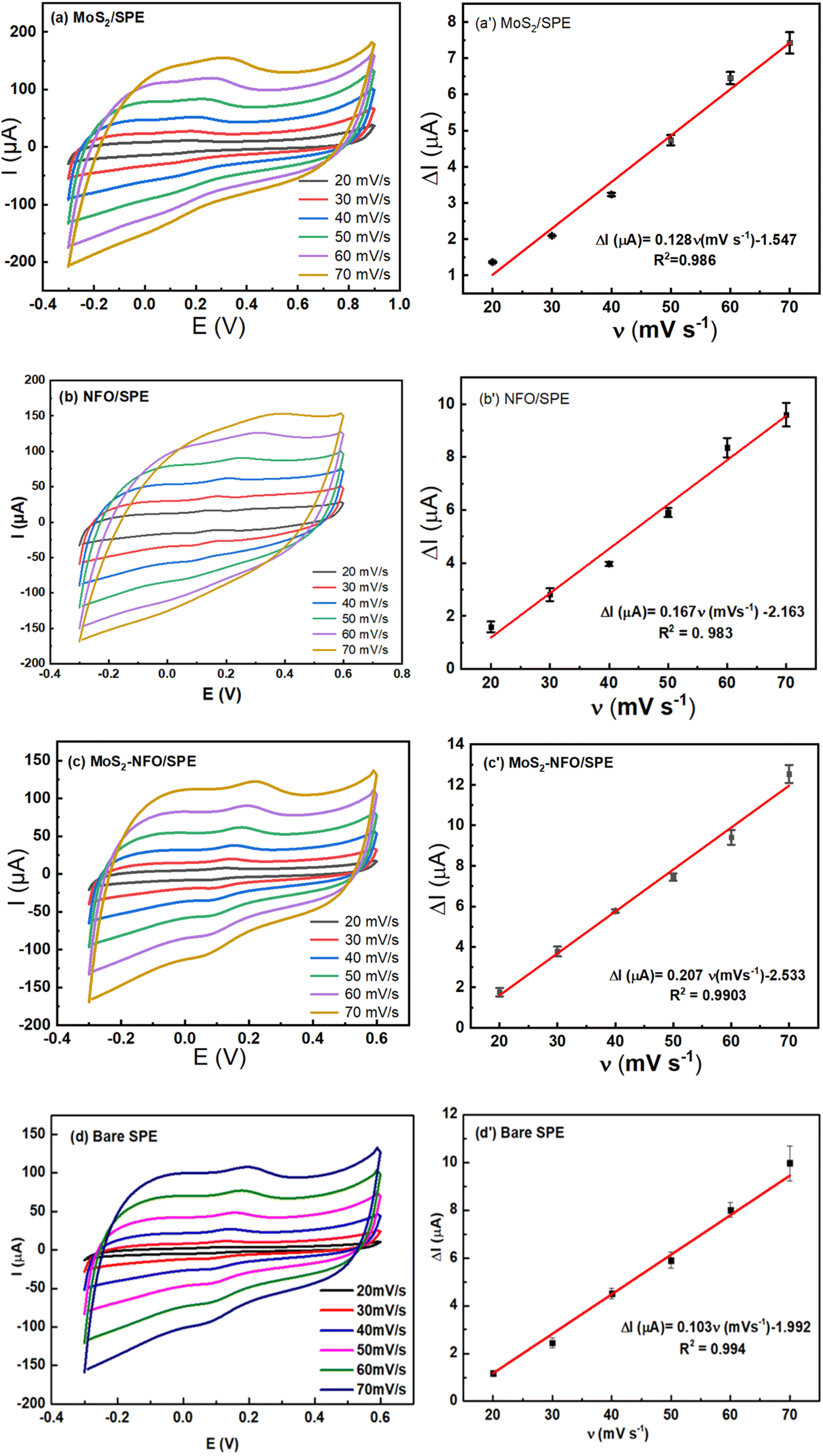
To investigate the reaction kinetics of CLB on the modified electrodes, CV measurements in pH 7.4 PBS buffer containing 50 μM CLB were carried out in the scan rate range from 20 to 70 mV s−1. The above results manifest that the anodic/cathodic peak current of all electrodes increased gradually with the increase in scan rate. The relationship between Ipa and v was illustrated in Fig. 5a′–c′, according to that it showed a high degree of linearity with linear regression equations of:
| Ip (μA) = 0.103ν (mV s−1) − 1.992 (R2 = 0.994) for bare SPE |
| Ip (μA) = 0.128ν (mV s−1) − 1.547 (R2 = 0.986) for MoS2/SPE |
| Ip (μA) = 0.167ν (mV s−1) − 2.163 (R2 = 0.983) for NFO/SPE |
| Ip (μA) = 0.207ν (mV s−1) − 2.533 (R2 = 0.990) for MoS2–NFO (2:1)/SPE |
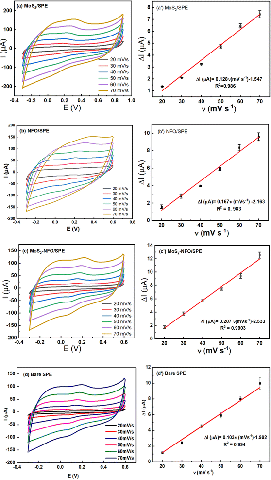 |
| | Fig. 5 CVs responses of 50 μM CLB at bare SPE (d), and the modified electrodes with MoS2 (a), NFO (b), and MoS2–NFO (2:1) (c) in 0.1 M PBS buffer at different scan rates; corresponding to the plot of peak current (I) versus scan rate (ν) (a′–d′). | |
From that, it can be inferred that the adsorption-controlled characteristics occurred in surface-confined reactions for their electrode process. It is interesting that from the slope value of Ip vs. scan rate, the adsorption capacity (Γ) of CLB on the various electrodes was estimated at 6.9 × 10⁻¹⁰, 4.53 × 10⁻¹⁰, 7.96 × 10⁻¹⁰, and 4.39 × 10⁻¹⁰ for NFO/SPE, MoS2/SPE, MoS2–NFO (2:1)/SPE, and bare SPE, respectively by using equation: Ip = n2F2AΓν/4RT. Besides, the effect of scan rate on the slight shift of peak potential was studied in detail. In this case, the linear relationship between Ep and the natural logarithm of scan rate ln(ν) was described in Fig. S4,† corresponding to the regression equations as:
| Ep (V) = 0.114ln(ν) (mV s−1) − 0.282 (R2 = 0.992) for bare SPE |
| Ep (V) = 0.119ln(ν) (mV s−1) − 0.203 (R2 = 0.989) for MoS2/SPE |
| Ep (V) = 0.169ln(ν) (mV s−1) − 0.398 (R2 = 0.991) for NFO/SPE |
| Ep (V) = 0.078ln(ν) (mV s−1) − 0.123 (R2 = 0.989) for MoS2–NFO (2:1)/SPE |
According to the Laviron theory, the relationship between Ep and scan rate in an adsorption-controlled irreversible process can be also expressed as:46–48
| Ep = E0 + (RT/αnF)ln(RTk0/αnF) − (RT/αnF)ln(ν) |
From that, the slope value of the above lines is equal to RT/αnF, thus, the value of αn can be also determined directly. As the number of electrons transferred is equal to 1, the electron transfer coefficient value (α) of bare SPE, NFO/SPE, MoS2/SPE, and MoS2–NFO (2:1)/SPE was calculated to be 0.225, 0.151, 0.207, and 0.328. More importantly, the value of the electron transfer rate constant (ks) of the redox reaction of CLB at these modified electrodes was also calculated based on the equation:
| ln(ks) = αln(1 − α) + (1 − α)lnα − ln(RT/nFν) − α(1 − α)(nFΔEp/RT) |
As shown by the results, the highest value of ks was recorded at MoS2–NFO (2:1)/SPE of approximately 0.504 s−1, while this value only reached about 0.283, 0.331, and 0.265 s−1 at NFO/SPE, MoS2/SPE, and bare SPE, respectively. By the calculated results, although in the previous section, MoS2/SPE showed many more excellent electrochemical characteristics of electrical conductivity and the values of EASA and ket, herein, the electrochemical behaviors of CLB on the MoS2–NFO (2:1)/SPE exhibited more impressive improvements. Not only possessed a higher electrochemical response of CLB but the kinetic parameters related to the redox reaction of CLB showed significant enhancements. As pointed out in our previous report, CLB is a complex and bulky organic molecule, resulting in a poor flat structure when adsorbed on the electrode surface. Along with that, the CLB molecules can be protonated and self-bonded with each other, leading to the creation of a huge steric hindrance, which causes remarkable dead spaces and limitation in the adsorption ability, interaction, electron transport, and charge diffusion of CLB onto the electrode surface. More importantly, the research proved that to get higher detection efficiency for CLB, the development of unique electrodes having better charge/electron transfer and electrocatalytic activity for the redox reactions of CLB should be given priority. Maybe, in this case, MoS2–NFO (2:1) nanocomposite structure through the suitable and effective combination supported considerably the strong interaction and charge/electron transfer between the active material and targeted CLB molecules. Furthermore, the co-existence of MoS2 and NFO provided many active sites for better electrocatalytic activity in the redox reaction of CLB, compared with other modified electrodes.
As we know, one of the most unique properties of NFO nanomaterial is the response to magnetic fields and good electrocatalytic ability similar to other magnetic nanomaterials. In our previous research, the positive influence of external stationary MF on electrochemical behaviors of Fe3O4–carbon spheres based-electrode as well as its sensing performance towards detecting chloramphenicol was thoroughly reported.8,29,30,32,49–51 Some impact mechanisms were proposed, explaining for the enhancement in mass transfer, ionic/charge diffusion in the electrolyte solution, as well as higher absorption capacity and better electrocatalytic ability at modified electrodes. According to this inevitable trend, the utilization of MF with the aim of promoting the inherent electrochemical characteristics of MoS2–NFO (2:1)/SPE such as electrical conductivity, adsorption capability, and electrocatalytic activity was carried out. Also, it is expected to enhance the electrolyte's physicochemical properties, in pursuit of better response-ability and higher sensing efficiency at the modified electrode.
Indeed, under the presence of external MF, the peak current response in the CV curves of MoS2–NFO (2:1)/SPE increased by about 5.4% compared with the initial value when without MF. Besides, the decrease in the ΔEp value was recorded, indicating the significant enhancement of electrical conductivity and transfer kinetics in the reversible electron transfer reaction of [Fe(CN)6]3−/4− probes (Fig. S5†). More interestingly, for further investigation of the MF impacts on the sensing performance of CLB, a series of kinetic parameters involving the redox reaction of CLB onto the electrode surface was calculated. Namely, from CVs curves obtained at various scan rates in 0.1 M PBS containing 50 μM CLB under the presence of MF, it still displays a linear relationship between Ip and scan rate (ν) in the range of 20–70 mV s−1 and it can be expressed as Ip (μA) = 0.413ν (mV s−1) − 5.188 (R2 = 0.995) as Fig. S6.† Furthermore, the linear equation of Ep and logarithm of scan rate was also estimated as Ep (V) = 0.148ln(ν) (mV s−1) − 0.278 (R2 = 0.978). According to that, ks and adsorption capacity (Γ) values of CLB achieved about 0.521 s−1 and 1.57 × 10⁻⁹, demonstrating the remarkable enhancement of electron transfer rate constant (ks) and adsorption capacity (Γ), compared with that of without MF under the same experimental condition.
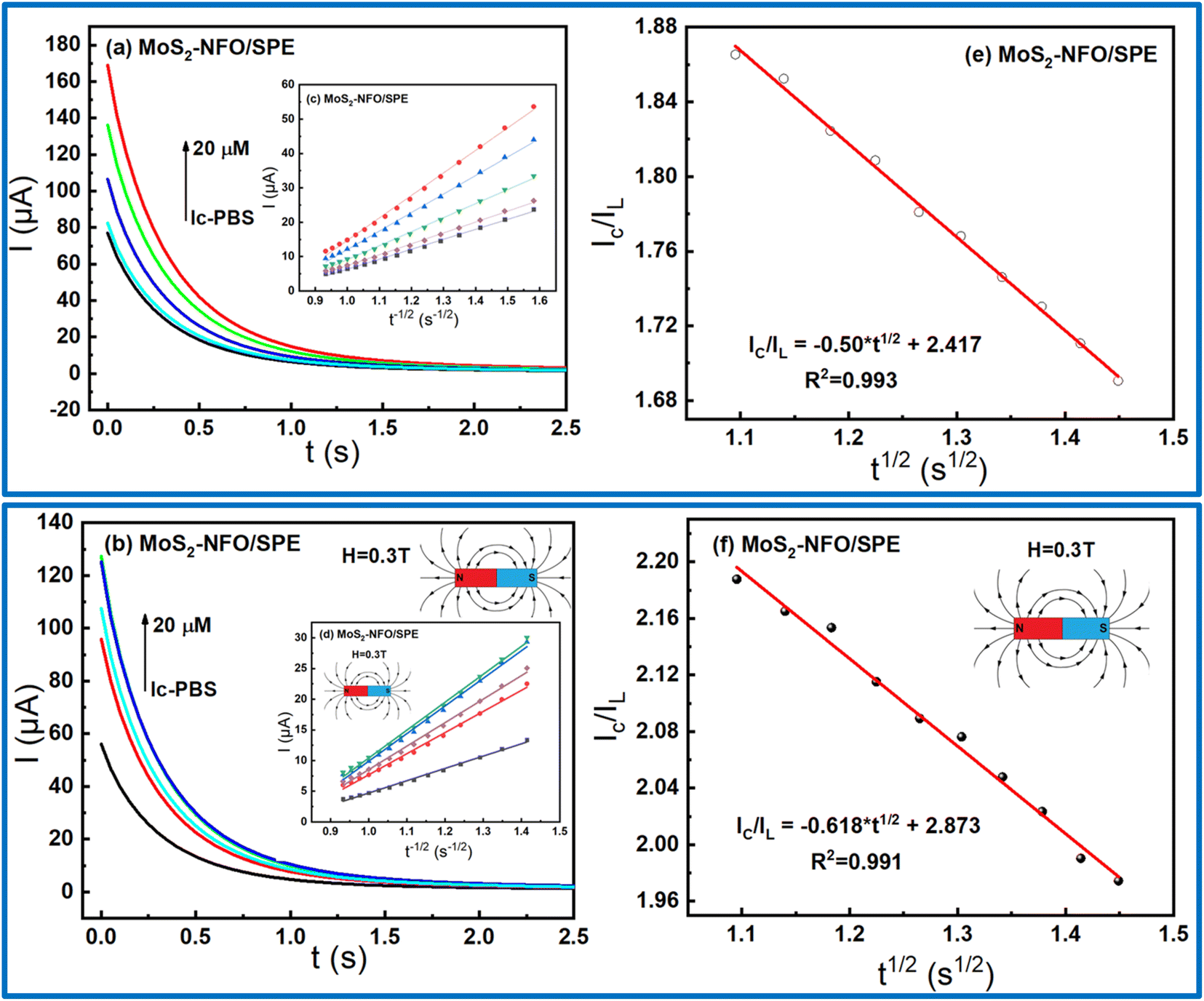
To get more insight into the influence of MF on electrocatalytic activity within MoS2–NFO (2:1)/SPE, CA measurements were taken with and without external MF. As shown in Fig. 6a and d, the linear increase of current response for diffusion-limited electrocatalytic techniques vs. t−1/2 were found at various concentrations in both two cases. Based on Cottrell's equation:29,52,53
the
D (cm
2 s
−1), which stands for the CLB diffusion coefficient, was determined around 7.89 × 10
−9 without using MF and 2.84 × 10
−8 with using MF, respectively. Besides, Galus method was employed to study the catalytic rate constant (
kct) to redox reaction between CLB molecules and active materials on the electrode surface
via tuning the working electrode potential at 0.25 V:
where
IC reflects the catalytic current of the redox reaction of CLB,
IL implies the limited current in 0.1 M PBS.
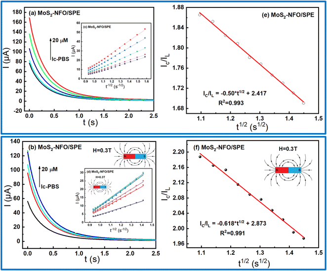 |
| | Fig. 6 (a and b) Chronoamperograms obtained at MoS2–NFO in 0.1 M PBS containing various concentrations of CLB with and without external MF; (c and d) plots of I vs. t−1/2; (e and f) plots of IC/IL vs. t1/2 at 15 μM CLB in 0.1 M PBS buffer. | |
From the direct slope values obtained in Fig. 6e and f at 20 μM CLB, the kcat were estimated around 0.0237 and 0.0329 without and with the support of MF. Consequently, it shows that the presence of MF offered many positive increases in the electrocatalytic activity of the electrode modified with MoS2–NFO (2:1) as expected.
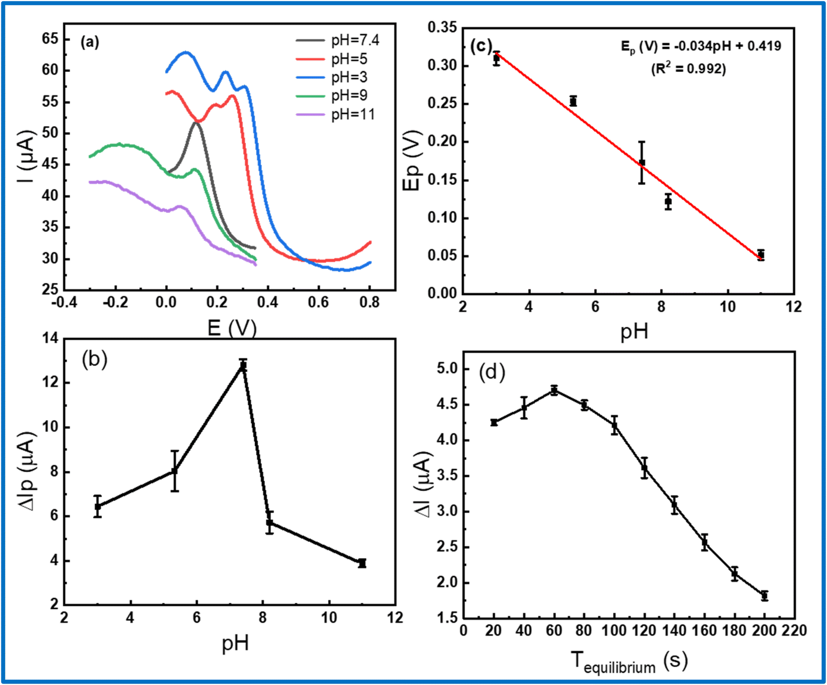
The electrochemical response was remarkably affected by the pH value of the PBS buffer and accumulation time during measurement. Thus, there is necessary to optimize the experimental conditions to obtain the highest electrochemical response. In this work, DPV measurements were analyzed at various pH values, using 1 M NaOH and H3PO4 solution for controlling the pH value in the range from 3 to 11. As displayed in Fig. 7b, it shows that the peak current gradually increased with increasing pH from 3 to 5 and reached a maximum value at pH 7.4, then decreased with over-increasing pH. With the maximum current, pH 7.4 was chosen as the optimal pH value for all the subsequent electrochemical measurements. In addition, the linear shift of peak potential with the increase of pH was found as expressed by the following equation: Ep (V) = −0.034pH + 0.419 (R2 = 0.992) in Fig. 7c. Fixing on the pH 7.4, the accumulation time was measured from 20 to 200 s to find the accumulation optimization. Fig. 7d exhibits the response current achieved a maximum value at 60 s and lower at other times, which could be attributed due to the saturated adsorption state of CLB onto the electrode surface.54 Finally, the pH of 7.4 and accumulation time of 60 s was employed as the best condition parameters for further electrochemical measurement in this work.
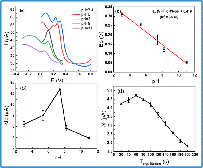 |
| | Fig. 7 (a) DPV curves on MoS2–NFO (2:1)/SPE in 0.1 M PBS containing 50 μM CLB at various pH values; (b and c) the plots of peak current vs. pH; (d) current response vs. Tequilibrium value from DPV measurements in 0.1 M PBS containing 20 μM CLB. | |
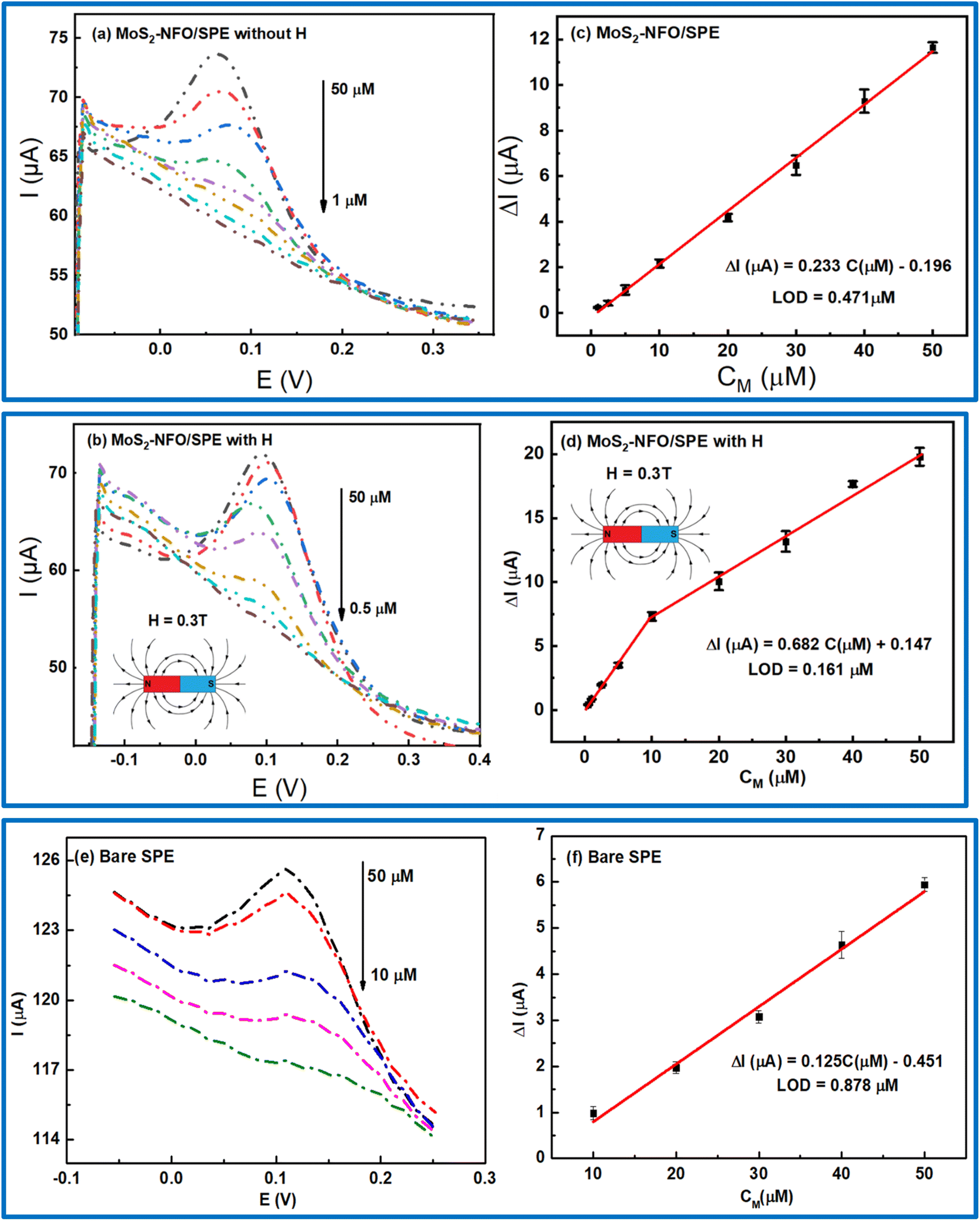
In order to investigate the sensitivity of electrochemical response with different concentrations of CLB at MoS2–NFO/SPE, especially in the experiment without and with MF, DPV were conducted in 0.1 M PBS buffer at the optimized experimental conditions. The DPV curves with different concentrations of CLB were displayed in Fig. 8a and b, respectively. All figures display that the peak current decreased to lower values with the reduction of CLB concentration. However, in comparison to the response current without and with MF, the electrochemical response with the presence of MF was considerably higher, corresponding to the wider linear range of CLB concentration from 0.5 to 50 μM, compared with that without the presence of MF from 1 to 50 μM, particularly, for bare SPE with the limited linear range from 10 to 50 μM. As a result, the linear relationship between the current response and the concentration of CLB was recorded in both three cases: ΔIp (μA) = 0.233CClB (μM) − 0.196 without MF; ΔIp (μA) = 0.682CCLB (μM) + 0.147 with MF; and ΔIp (μA) = 0.125CClB (μM) − 0.451 for bare SPE. The limit of detection (LOD) for bare SPE, and MoS2–NFO (2:1)/SPE without and with MF was computed from the calibration curve of 0.878, 0.471, and 0.161 μM, respectively (Fig. 8c, d and f).
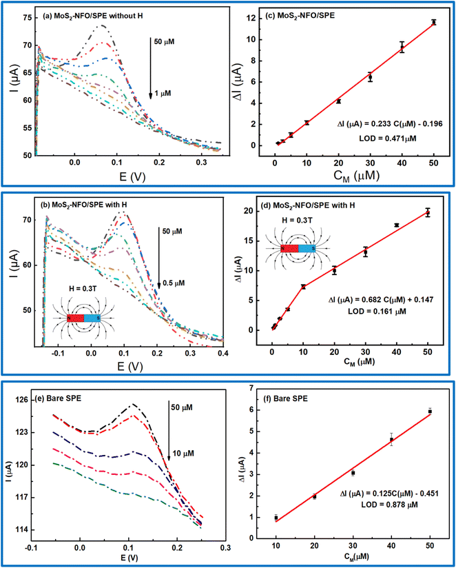 |
| | Fig. 8 (a, b and e) DPV curves recorded at the MoS2–NFO (2:1)-modified SPE in 0.1 M PBS (pH = 7.4) containing various concentrations of CLB without and with MF and bare SPE, respectively; (c, d and f) the plots of peak current as a function of CCAP in the different concentration ranges. | |
Investigating the stability, repeatability, and selectivity of the modified electrode, DPV measurements were carried out at MoS2–NFO (2:1)/SPE. Firstly, for evaluating the long-term stability, MoS2–NFO (2:1)/SPE was remained for 2 weeks at room temperature and atmosphere conditions, and then, it observed any change in the current response at the DPV curve for this electrode. As expected, only 3.4% of the initial value of the current response was reduced, exhibiting the good stability of the proposed electrode. Secondary, DPV measurements were repeated ten times in 0.1 M PBS (pH = 7.4) containing 20 μM CLB at 50 mV s−1 to assess the repeatability. The obtained result indicates that the MoS2–NFO (2:1)/SPE had outstanding repeatability with RSD value of 2.3%. Finally, some ions and organic molecules at 20-fold higher concentrations compared with 50 μM CLB such as Fe3+, Ni2+, Co2+, Cl−, NO3−, SO42−, Mg2+, Mn2+, ascorbic acid, glucose, urea, and nitrophenol were used as interfering substances to check the selectivity of the MoS2–NFO (2:1)/SPE towards the redox reactions of CLB. As pointed out, no significant influence on the current response of CLB was observed even under high concentration of interfering substances, corresponding to deviations below 4.2%. Notably, adding high concentrations of ascorbic acid owning an intense oxidation signal at about 0.17 V seems to lead to overlapping with the characteristic oxidation peak of CLB. In this case, a deconvolution tool to separate both individual signals was used. As a result, after deconvoluting this peak, the oxidation peak of CLB still displayed a high stability in response intensity as other studied interfering substances. The results recorded from stability, repeatability, and selectivity tests exhibited that MoS2–NFO (2:1)/SPE might be considered the best choice for the analytical application. More interestingly, in a comparison of sensing performance with other modified electrodes in the literature, it still exhibits a great enhancement in electrochemical performance toward CLB detection (Table 2). Besides, the presence of external MF is considered a promising development approach to increase performance instead of focusing on developing new synthesis methods and composites as in other reports.
To evaluate the practical application of MoS2–NFO/SPE as working electrode for detecting CLB, DPV measurements were taken in various spiked milk samples by the standard addition method. Milk concentration were added into 10-folds CLB sample. As exhibited in Table 1, it was clear that the recovery result of spiked samples was in the range from 90 to 96.32%. Meanwhile, RSD values of three times paralleled detection were obtained from 1.07 to 2.01%. These obtained results demonstrated that the proposed electrode based on MoS2–NFO was suitable accuracy and can be applied to determine the presence and concentration off CLB analysis in real matrixes.
Table 1 Determination of CLB in milk sample (n = 3)
| Samples |
Spiked (μM) |
Found (μM) |
Recovery (%) |
RSD (%) |
| Milk |
40 |
38.48 |
96.20 |
1.14 |
| 30 |
28.89 |
96.32 |
1.07 |
| 20 |
18.19 |
90.97 |
2.01 |
Table 2 Comparison of some analytical parameters in electrochemical sensors toward CLB detection
| Modified electrode |
Measurements |
Linear range (μM) |
LOD (μM) |
Repeatability |
Ref. |
| NiFe2O4–MoS2/SPE |
DPV |
1–50 |
0.471 |
97.7/10 |
This work |
| DPV |
0.5–50 |
0.161 |
97.7/10 |
This work |
| KVB-Nf (IP)/FCE |
DPV |
0.95–14.31 |
0.75 |
99.48/10 |
55 |
| BCNO/GCE |
DPV |
0.03–16 |
0.017 |
— |
56 |
| MoS2–Au–PEI–hemin/GCE |
DPV |
10–2000 |
1.92 |
— |
57 |
| Cl/MIP/Au |
DPV |
2–100 |
0.031 |
— |
58 |
4. Conclusions
In this study, NFO, MoS2 and MoS2–NFO nanomaterials were synthesized by using the hydrothermal and probe sonication methods. The crystallization, structure, particle size, morphology, and magnetic properties were observed and analysed by XRD, Raman, SEM, and VSM, respectively. The electrodes modified with MoS2, NFO, and MoS2–NFO were used, aiming to study electrochemical characteristics and sensing performance for the CLB sensitive detection under the absence/present applied magnetic fields via CV, EIS, DPV, and CA measurements. The obtained result pointed out that MoS2–NFO (2:1)/SPE was the best and most promising electrode for CLB detection. Also, the presence of MF enhanced the electrochemical features of MoS2–NFO (2:1)/SPE and a series of kinetic parameters in the redox reaction of CLB. By optimizing the experimental conditions in terms of the pH and accumulation time, the highest electrochemical response was recorded, corresponding to the pH at 7.4 and 60 s for the accumulation time. In addition, the work also reported the added advantages such as stability, repeatability, and selectivity of the proposed electrodes. The limit of detection for MoS2–NFO (2:1)/SPE in the absence/present MF were 0.471 and 0.161 μM, respectively, which promises MoS2–NFO (2:1)/SPE will be ideally suited to develop new sensor electrodes for further effective and fast detection towards different analytical molecules.
Conflicts of interest
There are no conflicts to declare.
Acknowledgements
This research was supported by the Vietnam National Foundation for Science and Technology Development (NAFOSTED) through a fundamental research project (103.02-2020.68). The authors would like to acknowledge the support for Raman, Electrochemical & UV-vis measurements from NEB Lab (Phenikaa University); SEM, XRD supports from GUST-VAST, VNU-Hanoi and VSM measurements from ITIMS-HUST.
References
- M. Kooti and A. N. Sedeh, Synthesis and Characterization of NiFe2O4 Magnetic Nanoparticles by Combustion Method, J. Mater. Sci. Technol., 2013, 29, 34–38 CrossRef CAS.
- K. N. Nithyayini, M. N. K. Harish and K. L. Nagashree, Electrochemical detection of nitrite at NiFe2O4 nanoparticles synthesised by solvent deficient method, Electrochim. Acta, 2019, 317, 701–710 CrossRef CAS.
- K. C. Babu Naidu and W. Madhuri, Hydrothermal synthesis of NiFe2O4 nano-particles: structural, morphological, optical, electrical and magnetic properties, Bull. Mater. Sci., 2017, 40, 417–425 CrossRef CAS.
- L. Sun, R. Zhang, Z. Wang, L. Ju, E. Cao and Y. Zhang, Structural, dielectric and magnetic properties of NiFe2O4 prepared via sol–gel auto-combustion method, J. Magn. Magn. Mater., 2017, 421, 65–70 CrossRef CAS.
- T. N. Pham, T. Q. Huy and A.-T. Le, Spinel ferrite (AFe2O4)-based heterostructured designs for lithium-ion battery, environmental monitoring, and biomedical applications, RSC Adv., 2020, 10, 31622–31661 RSC.
- M. Irfan, N. Dogan, A. Bingolbali and F. Aliew, Synthesis and characterization of NiFe2O4 magnetic nanoparticles with different coating materials for magnetic particle imaging (MPI), J. Magn. Magn. Mater., 2021, 537, 168150 CrossRef CAS.
- T. N. Pham, N. Van Cuong, N. X. Dinh, H. Van Tuan, V. N. Phan, N. Thi Lan, M. H. Nam, T. D. Thanh, V. D. Lam, N. Van Quy, T. Q. Huy, M.-H. Phan and A.-T. Le, Roles of Phase Purity and Crystallinity on Chloramphenicol Sensing Performance of CuCo2O4/CuFe2O4-based Electrochemical Nanosensors, J. Electrochem. Soc., 2021, 168, 026506 CrossRef CAS.
- A. B. Urgunde, G. Bahuguna, A. Dhamija, V. Kamboj and R. Gupta, Scalable Production of Nickel Cobaltite Nanoplates using Solution-Processed Inks for OER Electrocatalysis, Mater. Res. Bull., 2021, 142, 111380 CrossRef CAS.
- C. N. Chinnasamy, A. Narayanasamy, N. Ponpandian, R. Justin Joseyphus, B. Jeyadevan, K. Tohji and K. Chattopadhyay, Grain size effect on the Néel temperature and magnetic properties of nanocrystalline NiFe2O4 spinel, J. Magn. Magn. Mater., 2002, 238, 281–287 CrossRef CAS.
- A. Alarifi, N. M. Deraz and S. Shaban, Structural, morphological and magnetic properties of NiFe2O4 nano-particles, J. Alloys Compd., 2009, 486, 501–506 CrossRef CAS.
- S. Joshi, M. Kumar, S. Chhoker, G. Srivastava, M. Jewariya and V. N. Singh, Structural, magnetic, dielectric and optical properties of nickel ferrite nanoparticles synthesized by co-precipitation method, J. Mol. Struct., 2014, 1076, 55–62 CrossRef CAS.
- V. J. Angadi, B. Rudraswamy, K. Sadhana and K. Praveena, Structural and magnetic properties of manganese zinc ferrite nanoparticles prepared by solution combustion method using mixture of fuels, J. Magn. Magn. Mater., 2016, 409, 111–115 CrossRef CAS.
- Y. Zhang, W. Zhang, C. Yu, Z. Liu, X. Yu and F. Meng, Synthesis, structure and supercapacitive behavior of spinel NiFe2O4 and NiO@NiFe2O4 nanoparticles, Ceram. Int., 2021, 47, 10063–10071 CrossRef CAS.
- J.-P. Zhou, L. Lv, Q. Liu, Y.-X. Zhang and P. Liu, Hydrothermal synthesis and properties of NiFe2O4@BaTiO3 composites with well-matched interface, Sci. Technol. Adv. Mater., 2012, 13, 045001 CrossRef PubMed.
- Y. Xiao, J. Zai, B. Tian and X. Qian, Formation of NiFe2O4/Expanded Graphite Nanocomposites with Superior Lithium Storage Properties, Nano-Micro Lett., 2017, 9, 34 CrossRef PubMed.
- C. D. Valencia-Lopez, M. Zafra-Calvo, M. J. Martín de Vidales, V. Blanco-Gutierrez, E. Atanes-Sanchez, N. Merayo, F. Fernandez-Martinez, A. Nieto-Marquez and A. J. Dos santos-Garcia, Synthesis of NiFe2O4-LDH Composites with High Adsorption and Photocatalytic Activity for Methyl Orange Degradation, Inorganics, 2018, 6, 98 CrossRef.
- K. Sartori, A. Musat, F. Choueikani, J.-M. Grenèche, S. Hettler, P. Bencok, S. Begin-Colin, P. Steadman, R. Arenal and B. P. Pichon, A Detailed Investigation of the Onion Structure of Exchanged Coupled Magnetic Fe3−δO4@CoFe2O4@Fe3−δO4 Nanoparticles, ACS Appl. Mater. Interfaces, 2021, 13, 16784–16800 CrossRef CAS PubMed.
- R. Devi, S. Gogoi, H. S. Dutta, M. Bordoloi, S. K. Sanghi and R. Khan, Au/NiFe2O4 nanoparticle-decorated graphene oxide nanosheets for electrochemical immunosensing of amyloid beta peptide, Nanoscale Adv., 2020, 2, 239–248 RSC.
- A. R. B. Bayantong, Y.-J. Shih, C.-D. Dong, S. Garcia-Segura and M. D. G. de Luna, Nickel ferrite nanoenabled graphene oxide (NiFe2O4@GO) as photoactive nanocomposites for water treatment, Environ. Sci. Pollut. Res., 2021, 28, 5472–5481 CrossRef CAS PubMed.
- N. P. Satyanarayana Acharyulu, A. Sohan, P. Banoth, S. Chintalapati, S. Doshi, V. Reddy, C. Santhosh, A. N. Grace, L. De Los Santos Valladares and P. Kollu, Effect of the Graphene- Ni/NiFe2O4 Composite on Bacterial Inhibition Mediated by Protein Degradation, ACS Omega, 2022, 7, 30794–30800 CrossRef CAS PubMed.
- S. Fatemeh, Preparation of NiFe2O4@MIL-101(Fe)/GO as a novel nanocarrier and investigation of its antimicrobial properties, RSC Adv., 2022, 12, 7092–7102 RSC.
- J. Mao, Y. Wang, Z. Zheng and D. Deng, The rise of two-dimensional MoS2 for catalysis, Frontiers in Physics, 2018, 13, 138118 CrossRef.
- T. N. Pham, D. N. Xuan, T. H. Van, V. L. Khanh, T. L. Minh, V. Q. Nguyen, D. L. Vu and A.-T. Le, Insight into the Influence of Analyte Molecular Structure Targeted on MoS2-GO-Coated Electrochemical Nanosensors, Langmuir, 2021, 37, 12059–12070 CrossRef CAS PubMed.
- N. T. Anh, N. X. Dinh, T. N. Pham, L. K. Vinh, L. M. Tung and A.-T. Le, Enhancing the chloramphenicol sensing performance of Cu–MoS2 nanocomposite-based electrochemical nanosensors: roles of phase composition and copper loading amount, RSC Adv., 2021, 11, 30544–30559 RSC.
- Y. Yang, H. Fei, G. Ruan, C. Xiang and J. M. Tour, Edge-Oriented MoS2 Nanoporous Films as Flexible Electrodes for Hydrogen Evolution Reactions and Supercapacitor Devices, Adv. Mater., 2014, 26, 8163–8168 CrossRef CAS PubMed.
- M. Karpuraranjith, Y. Chen, B. Wang, J. Ramkumar, D. Yang, K. Srinivas, W. Wang, W. Zhang and R. Manigandan, Hierarchical ultrathin layered MoS2@NiFe2O4 nanohybrids as a bifunctional catalyst for highly efficient oxygen evolution and organic pollutant degradation, J. Colloid Interface Sci., 2021, 592, 385–396 CrossRef CAS PubMed.
- Y. Zhao, L. Xu, J. Yan, W. Yan, C. Wu, J. Lian, Y. Huang, J. Bao, J. Qiu, L. Xu, Y. Xu, H. Xu and H. Li, Facile preparation of NiFe2O4/MoS2 composite material with synergistic effect for high performance supercapacitor, J. Alloys Compd., 2017, 726, 608–617 CrossRef CAS.
- W. Fu, X. Xu, W. Wang, J. Shen and M. Ye, In-Situ Growth of NiFe2O4/2D MoS2 p–n Heterojunction Immobilizing Palladium Nanoparticles for Enhanced Visible-Light Photocatalytic Activities, ACS Sustainable Chem. Eng., 2018, 6, 8935–8944 CrossRef CAS.
- T. N. Pham, N. X. Dinh, V. M. Tien, V. H. Ong, R. Das, T. L. Nguyen, Q. H. Tran, D. T. Tran, D. L. Vu and A.-T. Le, Advances in magnetic field-assisted electrolyte's physicochemical properties and electrokinetic parameters: A case study on the response ability of chloramphenicol on Fe3O4@carbon spheres-based electrochemical nanosensor, Anal. Chim. Acta, 2022, 1229, 340398 CrossRef CAS PubMed.
- S. Luo, K. Elouarzaki and Z. J. Xu, Electrochemistry in Magnetic Fields, Angew. Chem., Int. Ed., 2022, 61, e202203564 CAS.
- P. Dunne and J. M. D. Coey, Influence of a Magnetic Field on the Electrochemical Double Layer, J. Phys. Chem. C, 2019, 123, 24181–24192 CrossRef CAS.
- L. T. Tufa, K.-J. Jeong, V. T. Tran and J. Lee, Magnetic-Field-Induced Electrochemical Performance of a Porous Magnetoplasmonic Ag@Fe3O4 Nanoassembly, ACS Appl. Mater. Interfaces, 2020, 12, 6598–6606 CrossRef CAS PubMed.
- R. P. Sivasankaran, N. Rockstroh, C. R. Kreyenschulte, S. Bartling, H. Lund, A. Acharjya, H. Junge, A. Thomas and A. Brückner, Influence of MoS2 on Activity and Stability of Carbon Nitride in Photocatalytic Hydrogen Production, Catalysts, 2019, 9, 695 CrossRef CAS.
- C. Cherpin, D. Lister, F. Dacquait and L. Liu, Study of the Solid-State Synthesis of Nickel Ferrite (NiFe2O4) by X-ray Diffraction (XRD), Scanning Electron Microscopy (SEM) and Raman Spectroscopy, Mater, 2021, 14, 2557 CrossRef CAS PubMed.
- C. M. Smyth, R. Addou, S. McDonnell, C. L. Hinkle and R. M. Wallace, Contact Metal–MoS2 Interfacial Reactions and Potential Implications on MoS2-Based Device Performance, J. Phys. Chem. C, 2016, 120, 14719–14729 CrossRef CAS.
- T. S. Sreeprasad, P. Nguyen, N. Kim and V. Berry, Controlled, Defect-Guided, Metal-Nanoparticle Incorporation onto MoS2 via Chemical and Microwave Routes: Electrical, Thermal, and Structural Properties, Nano Lett., 2013, 13, 4434–4441 CrossRef CAS PubMed.
- A. Ahlawat, V. G. Sathe, V. R. Reddy and A. Gupta, Mossbauer, Raman and X-ray diffraction studies of superparamagnetic NiFe2O4 nanoparticles prepared by sol–gel auto-combustion method, J. Magn. Magn. Mater., 2011, 323, 2049–2054 CrossRef CAS.
- A. Ahlawat and V. G. Sathe, Raman study of NiFe2O4 nanoparticles, bulk and films: effect of laser power, J. Raman Spectrosc., 2011, 42, 1087–1094 CrossRef CAS.
- M. A. Bissett, I. A. Kinloch and R. A. W. Dryfe, Characterization of MoS2-Graphene Composites for High-Performance Coin Cell Supercapacitors, ACS Appl. Mater. Interfaces, 2015, 7, 17388–17398 CrossRef CAS PubMed.
- H. Li, Q. Zhang, C. C. R. Yap, B. K. Tay, T. H. T. Edwin, A. Olivier and D. Baillargeat, From Bulk to Monolayer MoS2: Evolution of Raman Scattering, Adv. Funct. Mater., 2012, 22, 1385–1390 CrossRef CAS.
- S. Sahoo, A. P. S. Gaur, M. Ahmadi, M. J. F. Guinel and R. S. Katiyar, Temperature-Dependent Raman Studies and Thermal Conductivity of Few-Layer MoS2, J. Phys. Chem. C, 2013, 117, 9042–9047 CrossRef CAS.
- T. N. Pham, X. N. Pham, H. Thi Nguyen, T. Pham, Q. H. Tran and A.-T. Le, Exploiting the Balance Between Conductivity and Adsorption Capacity/Redox Electrocatalytic Ability In MIL-Based Porous Crystalline Materials for the Electrochemical Response, J. Electrochem. Soc., 2022, 169, 056521 CrossRef.
- S. K. Ponnaiah, P. Periakaruppan and B. Vellaichamy, New Electrochemical Sensor Based on a Silver-Doped Iron Oxide Nanocomposite Coupled with Polyaniline and Its Sensing Application for Picomolar-Level Detection of Uric Acid in Human Blood and Urine Samples, J. Phys. Chem. B, 2018, 122, 3037–3046 CrossRef CAS PubMed.
- A. S. Kumar, R. Shanmugam, N. Vishnu, K. C. Pillai and S. Kamaraj, Electrochemical immobilization of ellagic acid phytochemical on MWCNT modified glassy carbon electrode surface and its efficient hydrazine electrocatalytic activity in neutral pH, J. Electroanal. Chem., 2016, 782, 215–224 CrossRef CAS.
- N. Farvardin, S. Jahani, M. Kazemipour and M. M. Foroughi, The synthesis and characterization of 3D mesoporous
CeO2 hollow spheres as a modifier for the simultaneous determination of amlodipine, hydrochlorothiazide and valsartan, Anal. Methods, 2020, 12, 1767–1778 RSC.
- T. Tamiji and A. Nezamzadeh-Ejhieh, A comprehensive kinetic study on the electrocatalytic oxidation of propanols in aqueous solution, Solid State Sci., 2019, 98, 106033 CrossRef CAS.
- Y. Li, X. Shi and J. Hao, Electrochemical behavior of glassy carbon electrodes modified by multi-walled carbon nanotube/surfactant films in a buffer solution and an ionic liquid, Carbon, 2006, 44, 2664–2670 CrossRef CAS.
- S. Saadati, A. Salimi, R. Hallaj and A. Rostami, Layer by layer assembly of catalase and amine-terminated ionic liquid onto titanium nitride nanoparticles modified glassy carbon electrode: Study of direct voltammetry and bioelectrocatalytic activity, Anal. Chim. Acta, 2012, 753, 32–41 CrossRef CAS PubMed.
- F. A. Garcés-Pineda, M. Blasco-Ahicart, D. Nieto-Castro, N. López and J. R. Galán-Mascarós, Direct magnetic enhancement of electrocatalytic water oxidation in alkaline media, Nat. Energy, 2019, 4, 519–525 CrossRef.
- Y. Zhang, C. Liang, J. Wu, H. Liu, B. Zhang, Z. Jiang, S. Li and P. Xu, Recent Advances in Magnetic Field-Enhanced Electrocatalysis, ACS Appl. Energy Mater., 2020, 3, 10303–10316 CrossRef CAS.
- J. Saha, R. Ball and C. Subramaniam, Premagnetized Carbon-Catalyst Interface Delivering 650% Enhancement in Electrocatalytic Kinetics of Hydrogen Evolution Reaction, ACS Sustainable Chem. Eng., 2021, 9, 7792–7802 CrossRef CAS.
- P. Talebizadehsardari, Z. Aramesh-Boroujeni, M. M. Foroughi, A. Eyvazian, S. Jahani, H. R. Faramarzpour, F. Borhani, M. Ghazanfarabadi, M. Shabani and A. H. Nazari, Synthesis of carnation-like Ho3+/Co3O4 nanoflowers as a modifier for electrochemical determination of chloramphenicol in eye drop, Microchem. J., 2020, 159, 105535 CrossRef CAS.
- L. Wang, T. Meng, J. Sun, S. Wu, M. Zhang, H. Wang and Y. Zhang, Development of Pd/Polyoxometalate/nitrogen-doping hollow carbon spheres tricomponent nanohybrids: A selective electrochemical sensor for acetaminophen, Anal. Chim. Acta, 2019, 1047, 28–35 CrossRef CAS PubMed.
- Y. Li, Y. Gao, Y. Cao and H. Li, Electrochemical sensor for bisphenol A determination based on MWCNT/melamine complex modified GCE, Sens. Actuators, B, 2012, 171–172, 726–733 CrossRef CAS.
- K. Zhang, Development of New Electrochemical Sensor based on Kudzu Vine Biochar Modified Flexible Carbon Electrode for Portable Wireless Intelligent Analysis of Clenbuterol, Int. J. Electrochem. Sci., 2020, 7326–7336 CrossRef.
- H. Jing, H. Ouyang, W. Li and Y. Long, Molten salt synthesis of BCNO nanosheets for the electrochemical detection of clenbuterol, Microchem. J., 2022, 178, 107359 CrossRef CAS.
- Y. Yang, H. Zhang, C. Huang, D. Yang and N. Jia, Electrochemical non-enzyme sensor for detecting clenbuterol (CLB) based on MoS2-Au-PEI-hemin layered nanocomposites, Biosens. Bioelectron., 2017, 89, 461–467 CrossRef CAS PubMed.
- L. Liu, Electrochemical sensor based on molecularly imprinted film for high sensitivity detection of clenbuterol prepared using sol-gel method, Int. J. Electrochem. Sci., 2021, 16, 210411 CrossRef CAS.
Footnotes |
| † Electronic supplementary information (ESI) available. See DOI: https://doi.org/10.1039/d3ra01136d |
| ‡ V. M. Tien and O. V. Hoang contributed equally to this work. |
|
| This journal is © The Royal Society of Chemistry 2023 |
Click here to see how this site uses Cookies. View our privacy policy here. 
 Open Access Article
 This Open Access Article is licensed under a Creative Commons Attribution-Non Commercial 3.0 Unported Licence
 *a,
Nguyen Quang Hoad,
Thi Lan Nguyene,
Pham Duc Thangab,
Le Khanh Vinhf,
Pham Thi Nhat Trinhh,
Doan Thi Ngoc Thanhi,
Le Minh Tung*g and
Anh-Tuan Le
*a,
Nguyen Quang Hoad,
Thi Lan Nguyene,
Pham Duc Thangab,
Le Khanh Vinhf,
Pham Thi Nhat Trinhh,
Doan Thi Ngoc Thanhi,
Le Minh Tung*g and
Anh-Tuan Le