
 Open Access Article
 This Open Access Article is licensed under a Creative Commons Attribution-Non Commercial 3.0 Unported Licence
Flexible cellulose-based piezoelectric composite membrane involving PVDF and BaTiO3 synthesized with the assistance of TEMPO-oxidized cellulose nanofibrils†
Meilin Liab,
Bei Jiangab,
Shuoang Caoab,
Xinyi Songab,
Yuanqiao Zhangab,
Lijun Huangab and
Quanping Yuan *ab
*ab
aSchool of Resources, Environment and Materials, Guangxi University, Nanning 530004, China. E-mail: yuanquanping@gxu.edu.cn
bState Key Laboratory of Featured Metal Materials and Life-cycle Safety for Composite Structures, MOE Key Laboratory of New Processing Technology for Nonferrous Metals and Materials, Guangxi University, Nanning 530004, China
First published on 31st March 2023
Abstract
High-performance flexible barium titanate (BaTiO3)-based piezoelectric devices have gained much attention. However, it is still a challenge to prepare flexible polymer/BaTiO3-based composite materials with uniform distribution and high performance due to the high viscosity of polymers. In this study, novel hybrid BaTiO3 particles were synthesized with assistance of TEMPO-oxidized cellulose nanofibrils (CNFs) via a low-temperature hydrothermal method and explored for their application in piezoelectric composites. Specifically, Ba2+ was adsorbed on uniformly dispersed CNFs with a large amount of negative charge on their surface, which nucleated, resulting in the synthesis of evenly dispersed CNF-BaTiO3. The obtained CNF-BaTiO3 possessed a uniform particle size, few impurities, high crystallinity and dispersity, high compatibility with the polymer substrate and surface activity due to the existence of CNFs. Subsequently, both polyvinylidene fluoride (PVDF) and TEMPO-oxidized CNFs were employed as piezoelectric substrates for the fabrication of a CNF/PVDF/CNF-BaTiO3 composite membrane with a compact structure, displaying the tensile strength of 18.61 ± 3.75 MPa and elongation at break of 3.06 ± 1.33%. Finally, a thin piezoelectric generator (PEG) was assembled, which output a considerable open-circuit voltage (4.4 V) and short-circuit current (200 nA), and could also power a light-emitting diode and charge a 1 μF capacitor to 3.66 V in 500 s. Its longitudinal piezoelectric constant (d33) was 5.25 ± 1.04 pC N−1 even with a small thickness. It also exhibited high sensitivity to human movement, outputting a voltage of about 9 V and current of 739 nA for only a footstep. Thus, it exhibited good sensing property and energy harvesting property, presenting practical application prospects. This work provides a new idea for the preparation of hybrid BaTiO3 and cellulose-based piezoelectric composite materials.
Introduction
With the increasing demand for sustainable energy, mechanical energy as a widely existing form of energy in the living environment has attracted significant attention, such as body movements, strikes, and acoustic waves.1,2 The piezoelectric effect and piezoelectric devices are generally employed to realize the conversion of mechanical energy to electric energy. As a common piezoelectric material, barium titanate (BaTiO3) is a very attractive material due to its lead-free property and high piezoelectricity.3–5 However, as a type of inorganic piezoelectric material with high density and brittle characteristic, it is difficult to bend it in complex shapes, and thus its flexible application is extremely limited.6 Accordingly, to address this problem, flexible polymers, such as polydimethylsiloxane (PDMS),7 poly(vinylidene fluoride) (PVDF)8 and its copolymers,9 and cellulose10–12 have been used to fabricate flexible composites with BaTiO3 via direct mixing or in combination with modification processes.However, it is challenging to prepare homogeneous composite materials with high performance because most flexible substrates are sticky and hydrophobic, making it difficult for nanoparticles to be sufficiently separated and dispersed. Considering these difficulties, the approach to add conductive materials as dispersants and a third phase material in the composites to form a hybrid structure, such as carbon nanotubes,13 conductive polymers,14 graphene15 and metal nanorods,16 has been developed.17 Moreover, it is feasible to prepare polymer composites containing BaTiO3-based hybrid particles with a core–shell structure, which exhibit good dispersity, fast response and high piezoelectric performance.18,19 In addition, it has been demonstrated that three-phase BaTiO3-based nanocomposites with a combination of either fillers or polymer matrix exhibit enhanced dielectric properties.20
In the case of the synthesis of BaTiO3, traditionally, industry mainly employ the solid-state reaction, which has the drawbacks of producing materials with a large particle size, uneven distribution, impurities, and low chemical activity.21 The electrical properties of BaTiO3 are highly dependent on its high purity, sintering property and uniform distribution.22 Thus, many methods, such as precipitation method,23 sol–gel method,24 hydrothermal method25–27 and other wet chemical methods have been developed to overcome these problems. Particularly, BaTiO3 prepared via the hydrothermal method has the advantages of lower impurity content, higher chemical activity, intact grain structure, small and uniform particle size distribution, less agglomeration and high sintering activity, as well as low cost and environmental friendliness.28 Notably, although its stoichiometry is affected by the solvent and dosage, this disadvantage disappears during large-scale production.22 The published research on the synthesis of BaTiO3 mainly focused on the effect of the Ti/Ba mole ratio,29 reaction temperature,25,30 reaction time,30 and pH30,31 of the reaction system on the structure and properties of BaTiO3. Moreover, BaTiO3 can be grown on some substrates via hydrothermal synthesis, such as multi-walled carbon nanotubes32 and graphene oxide (GO) to enhance its structure. In the hydrothermal growth of BaTiO3, the base of GO with abundant oxygen-containing groups alters the morphology of BaTiO3 and narrows its size distribution, also achieving its homogeneous distribution. Specially, the oxygen-containing groups of GO can heal the oxygen vacancies in the hybridized BaTiO3, which improve its piezoelectric properties.33
Cellulose nanofibrils (CNF), as a type of natural cellulose material, have a high specific surface area, length–diameter ratio, strength and film-forming performance, as well as certain piezoelectric properties. Accordingly, they can be assembled into a variety of nanostructures to meet the design requirements of energy devices. The addition of eco-friendly nanocellulose to energy-related devices is very promising in solving the related environmental problems. Moreover, it has been demonstrated that nanocellulose is an excellent dispersion medium.34 Therefore, it can further solve the problem of easy aggregation of the filler in the polymer matrix to a certain extent. After TEMPO treatment, the hydroxyl groups can be oxidized to carboxy groups, and consequently CNFs exhibit higher dispersity,35,36 which can play a similar role to GO.33
In this work, CNFs with abundant carboxy groups were prepared using a method involving the TEMPO-NaBr-NaClO system and directly added to synthesize BaTiO3 via a low-temperature hydrothermal method. Subsequently, BaTiO3 was combined with two substrates of PVDF and CNFs via ultrasonic dispersion, self-assembly, and hot pressing to fabricate the CNF/PVDF/CNF-BaTiO3 piezoelectric composite membrane. In the reaction system, the metal cations (Ba2+) adsorbed on the surface oxygen-containing groups of CNFs acted as nucleation points to improve the size distribution and crystal structure. The excessive contact and aggregation of BaTiO3 particles could be inhibited by the stable network structure constructed by TEMPO-oxidized CNF. Furthermore, the uniform dispersion of the synthesized BaTiO3 was effectively improved and its particle size reduced. Intriguingly, CNF-BaTiO3 is compatible with PVDF and CNFs in aqueous media, and the combination of CNF-BaTiO3 and the substrates should be very compact. Consequently, the flexible piezoelectric composite membranes exhibited a considerable piezoelectric effect to collect mechanical energy and sensing performance for health monitoring. This study has high reference value for the modification and improvement of the structure and properties of BaTiO3 and piezoelectric functionalization of CNF.
Experimental
Materials
Bleached kraft pulp of coniferous wood was provided by Tianjin Woodelf Biotechnology Co., Ltd (Tianjin, China), containing 78.2 wt% cellulose, 20.1 wt% hemicellulose, and less than 0.5 wt% content of residual lignin. 2,2,6,6-Tetramethylpiperidine-1-oxyl (TEMPO) was procured from Shanghai Macklin Biochemical Co., Ltd (Shanghai, China). Sodium hypochlorite solution (NaClO, analytical reagent) with available chlorine greater than or equal to 10% and sodium bromide (NaBr, analytical reagent, ≥99.0%) were obtained from Chengdu Jinshan Chemical Reagent Co., Ltd (Chengdu, China). Barium hydroxide hydrate (H2BaO2·xH2O, 99.99%) was obtained from Aladdin Holdings Group Co., Ltd (Shanghai, China). Tetrabutyl titanate (Ti(OBu)4, analytical reagent, ≥99.0%) was purchased from Tianjin Damao Chemical Reagent Factory (Tianjin, China). PVDF-TrFE (Arkema, France) with an average molecular weight of 180![[thin space (1/6-em)]](https://www.rsc.org/images/entities/char_2009.gif) 000 g mol−1 (Mw) and 71000 g mol−1 (Mn) as well as DMF (analytical reagent, 99.5%), which was provided by Sinopharm Chemical Reagent Co. Ltd (Shanghai, China), were applied in this work. The CNF dispersion (Tianjin Woodelf Biotechnology Co., Ltd, Tianjin, China) with a concentration of 1.08 wt% was made of bleached sulfate pulp (spruce) and via the method of TEMPO oxidation treatment and high-pressure homogenization.
000 g mol−1 (Mw) and 71000 g mol−1 (Mn) as well as DMF (analytical reagent, 99.5%), which was provided by Sinopharm Chemical Reagent Co. Ltd (Shanghai, China), were applied in this work. The CNF dispersion (Tianjin Woodelf Biotechnology Co., Ltd, Tianjin, China) with a concentration of 1.08 wt% was made of bleached sulfate pulp (spruce) and via the method of TEMPO oxidation treatment and high-pressure homogenization.
Preparation of various TEMPO-oxidized CNFs
CNFs were prepared using the method involving TEMPO-NaBr-NaClO system.37 Firstly, after the catalyst (TEMPO, 0.048 g), cocatalyst (NaBr, 0.48 g) and oxidizing agent (NaClO, 5.07 mL × X) (X, addition content of NaClO was set as 4, 6, 8, 10, 12, 14 mmol g−1, respectively) was added to the crushed pulp (3 g) under stirring at 600 rpm, 0.1 M NaOH and 0.1 M HCl were used to maintain the pH of the reaction system, which was stabilized at 10 after the reaction began. In this reaction process, when the pH was maintained at 10.00 ± 0.01 for 15 min, 10 mL of ethyl alcohol was added to quench the reaction, and then stirring continue the stir for 15 min. The obtained intermediate product was centrifuged and washed with deionized water until it was neutral. The cellulose suspension was ultrasonically dispersed at a power of 1000 W for 30 min in an ice-bath to obtain the CNF dispersion. Finally, the concentration of CNF dispersion was tested and calculated after dried at 105 °C for 12 h. The CNFs prepared with various contents of oxidizing agent were denoted as 4CNF, 6CNF, 8CNF, 10CNF, 12CNF, and 14CNF, respectively.Synthesis of CNF-BaTiO3
Barium hydroxide hydrate (H2BaO2·xH2O) particles (10 mmol) were added to a 200 mL beaker with 20 mL deionized water. Then the beaker was placed in a 60 °C water bath and stirred magnetically for 30 min to dissolve the particles. H2BaO2·xH2O solution together with 20 mL CNF dispersion (1 wt%, the mass percent of pure CNF relative to the total weight of H2BaO2·xH2O), which was subjected to ultrasonic treatment for 30 min at 1000 W and added to 10 mL ethanol solution of butyl titanate (Ti(OBu)4, content of 10 mmol) and stirred, before pouring into a hydrothermal reactor. The reactor was placed in an oven at 120 °C for 12 h, and then cooled naturally to room temperature. The reaction product was washed with deionizing water several times until the filtered liquid was neutral, and the CNF-BaTiO3 powder was finally obtained after freeze-drying for 12 h.CNFs with various oxidation degrees were prepared using various contents of NaClO (4, 6, 8, 10, 12, and 14 mmol g−1) and adopted to synthesize a series of CNF-BaTiO3, denoted as 4CNF-BaTiO3, 6CNF-BaTiO3, 8CNF-BaTiO3, 10CNF-BaTiO3, 12CNF-BaTiO3, and 14CNF-BaTiO3, respectively. In addition, BaTiO3 powder without CNF was prepared via the same method, which was named 0CNF-BaTiO3.
Fabrication of CNF/PVDF/CNF-BaTiO3 piezoelectric composite membrane
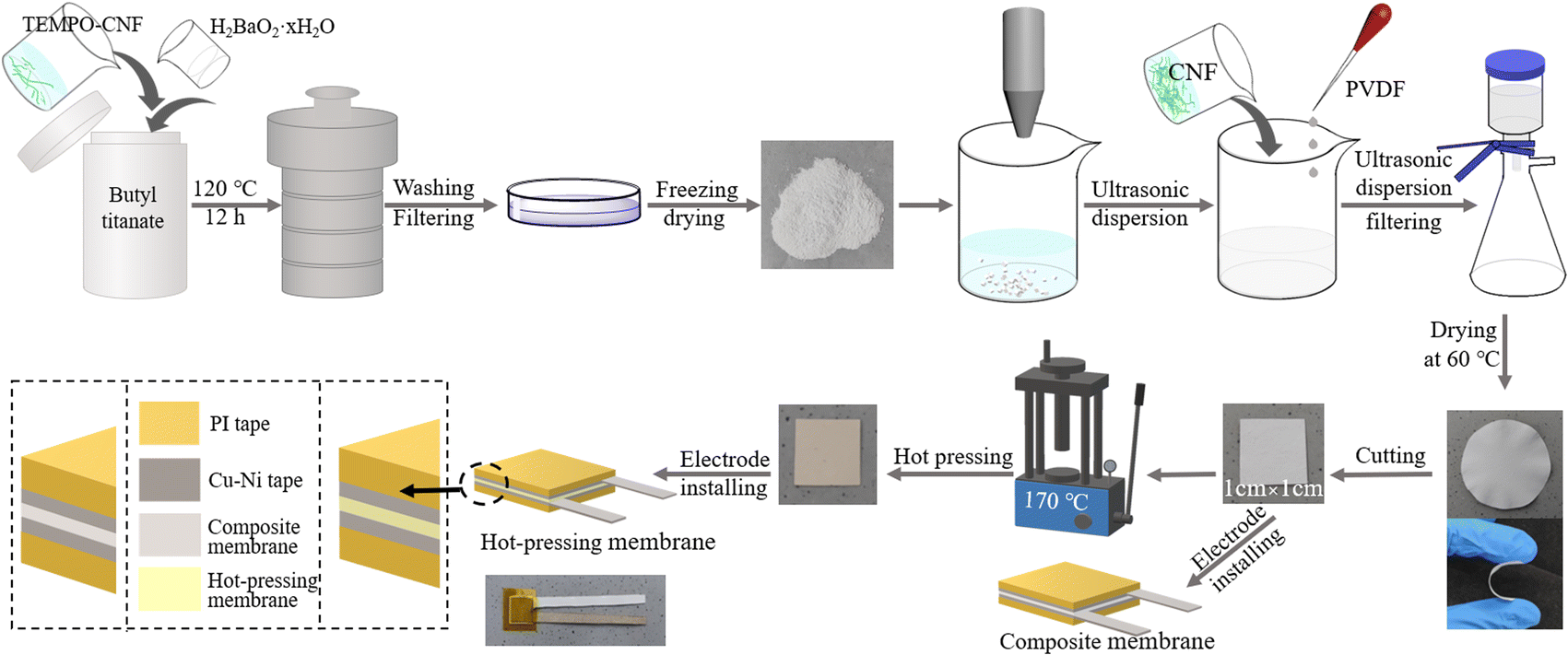
CNF-BaTiO3 was weighed (0.05 g, 50 wt% of ratio to the composite membrane) and put in a 200 mL beaker with 20 mL of deionized water, followed by ultrasound dispersion for 30 min. Then 0.03 g commercial CNF dispersion (CNF, 30 wt% of ratio to the composite membrane) was weighed and put in another beaker (capacity of 200 mL) with 20 mL of deionized water. The CNF dispersion was obtained after ultrasonic treatment for 30 min at 1000 W. Besides, 0.02 g PVDF (20 wt% of ratio to the composite membrane) dissolved in 10 mL DMF.The above-mentioned three types of solution were mixed via an ultrasonic process (1000 W, 30 min), followed by vacuum filtration using a 0.22 μm organic filter, and then left in the air for 1 h. Afterwards, the obtained composite membrane was placed in two plates of a pressing machine at 60 °C for 8 h, and then the composite membranes were obtained.
The composite membrane was cut into small pieces with a size of 1 cm × 1 cm. Subsequently, it was directly affixed with Cu–Ni conductive tape (0.9 cm × 0.9 cm) to a polyimide (PI) film, as shown in Fig. 1. The composite membranes prepared with the series of CNF-BaTiO3 were named CNF/PVDF/4CNF-BaTiO3, CNF/PVDF/6CNF-BaTiO3, CNF/PVDF/8CNF-BaTiO3, CNF/PVDF/10CNF-BaTiO3, CNF/PVDF/12CNF-BaTiO3, CNF/PVDF/14CNF-BaTiO3 and CNF/PVDF/0CNF-BaTiO3 piezoelectric composite membrane, respectively. Alternatively, the cut composite membrane was further hot pressed for 30 min at 170 °C under 20 MPa, and then affixed to electrodes to form the hot-pressed piezoelectric composite membranes.
 | ||
| Fig. 1 Schematic diagram for the fabrication of the composite membrane and PEG. | ||
After the piezoelectric composite membranes were encapsulated with two pieces of PI films, piezoelectric generators (PEGs) containing the various CNF-BaTiO3 were finally fabricated according to the above-mentioned process. The specific process for the preparation of the composite membrane and PEG can is presented in Fig. 1.
Characterization and measurement
Scanning electron micrographs were obtained using a field emission scanning electron microscope at 10 kV (FE-SEM, SU-8020, HITACHI), and high-resolution transmission electron microscopy (HRTEM) images were taken using a TEM (TECNAI G2 F30, FEI) at 300 kV. The phase structure of CNF-BaTiO3 and the composite membranes was characterized via X-ray powder diffraction (XRD, Rigaku D/MAX 2500V, Rigaku Corporation) with Cu Kα radiation (λ = 0.15406 nm) at a scanning rate of 8° min−1. Fourier Transform infrared spectra (FTIR) were obtained using an infrared spectrophotometer (IRTracer-100, SHIMADZU). Specimens of 4 mm × 10 mm were employed to carry out the tensile test using a tensile testing machine (ZQ-990A, Zhiqu Precision Instruments Co., Ltd) at a speed of 1 mm min−1. To measure the piezoelectric output data, the samples were cut into 1 cm × 1 cm and affixed to electrodes with Cu–Ni tape on both sides (as seen in Fig. 1). A charge acquisition system (KE6259-FNG-SYS) with an acquisition card (USB6529) and a Keithley electrometer (6514) were used to measure the open-circuit voltage (VOC) and short-circuit current (ISC), as well as the sensing performance. The longitudinal piezoelectric constant (d33) of the composite membranes was measured using a ZJ-6A quasi-static d33 tester (Institute of Acoustics, Chinese Academy of Sciences).Results and discussion
Structure and morphology characterization of CNF-BaTiO3
As shown in Table S1,† the average particle size of the CNF-BaTiO3 powder synthesized with the assistance of CNFs at different oxidation degrees was smaller than that of BaTiO3 synthesized without the assistance of CNF. According to the SEM analysis, as shown in Fig. 2a, c and S1a–e,† less agglomeration phenomenon occurred between the BaTiO3 particles synthesized with CNF assistance, and the dispersion was more uniform and had a smaller particle size compared with that without the assistance of CNF (Table S1†). This phenomenon was also demonstrated in the distribution of Ba, Ti, O, and C elements, as shown in Fig. 2b. This is attributed to the fact that the TEMPO-oxidized CNFs have a large amount of negative charge on their surface, which generates electrostatic adsorption with Ba2+ in the reaction system. Consequently, Ba2+ was fixed on the highly uniform and dispersed CNF surface, and nucleated and grew evenly and dispersedly.38,39 The specific mechanism can be seen in Fig. 2i. Moreover, CNFs interacted with the BaTiO3 nanoparticles through hydrogen bonding due to the presence of rich hydroxyl groups and large specific surface area. Therefore, the synthesized BaTiO3 particles could be fixed on the surface of CNFs to some extent, thus avoiding its excessive aggregation and sedimentation in the reaction system.40 As shown in Fig. 2a, BaTiO3 was mostly in the shape of a “square”. When CNFs prepared with a small content of NaClO were used, the particle size of the synthesized powder was large and uneven due to their low carboxyl content (Table S1†), and some particles also agglomerated (Fig. 2a, c and S1a–e†). This may be caused by the uneven solubility of the primary particles and uneven distribution of CNFs, resulting in different growth rates,41 and the concentration of CNFs was too low to support the growth of BaTiO3. However, when the degree of oxidation (dosage of NaClO) was high, the particle size of the powder became smaller and its distribution was more uniform. In addition, as can be seen in the elemental surface distribution in Fig. 2b, Ba and Ti elements of BaTiO3 and C element of CNFs were evenly distributed, further indicating that CNFs uniformly existed in the synthesized BaTiO3. The analysis of the above-mentioned results indicated that the addition of CNFs enabled the nucleation and dispersion of BaTiO3 in the reaction system, as well as reduced the agglomeration phenomenon during the synthesis of BaTiO3.39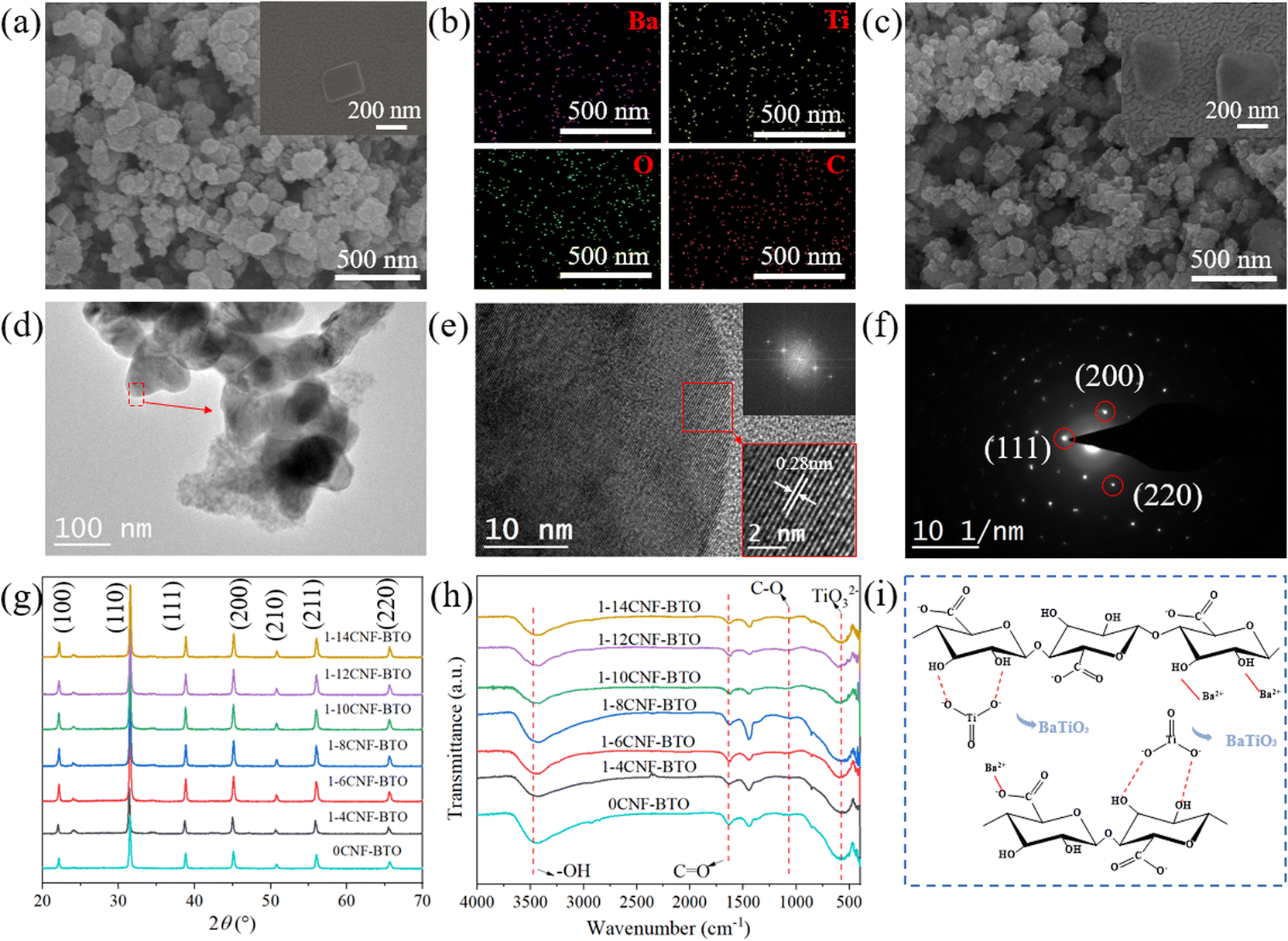 | ||
| Fig. 2 (a) FE-SEM image of 10CNF-BaTiO3, (b) Ba, Ti, O, and C element distribution on (a), and (c) FE-SEM image of 0CNF-BaTiO3. TEM (d), HRTEM (e), SAED pattern and FFT (f) of the 10CNF-BaTiO3. XRD (g) and FTIR spectra (h) of CNF-BaTiO3. (i) Synthesis mechanism of the hybrid BaTiO3 particles with the assistance of TEMPO-oxidized CNF. | ||
The spacing of the crystal plane of the synthesized 10CNF-BaTiO3 was determined to be 0.28 nm via HRTEM analysis, as shown in Fig. 2d and e, and the (111), (200), and (220) crystal faces corresponding to BaTiO3 were observed in the SAED pattern and FFT analysis, as shown in Fig. 2f.42,43 As shown in Fig. 2g, the diffraction peaks of CNF-BaTiO3 appeared at the 2θ values of 22.16°, 31.52°, 38.83°, 45.12°, 50.79°, 56.04°, and 65.66°, respectively, corresponding to the Bragg reflection of the (100), (110), (111), (200), (210), (211), and (220) crystal faces, respectively. Based on the XRD diffraction pattern of BaTiO3 and the PDF card (JCPDS card no. 31-0174), it was confirmed that BaTiO3 was synthesized on the CNF substrate, and the weak peak appearing at around 24° indicates the presence of a small amount of BaCO3 impurity in CNF-BaTiO3 (JCPDS card No. 05-0378).44 However, the relatively weak characteristic peak of CNFs could be hardly seen in the pattern of CNF-BaTiO3 due to their small addition amount. Thus, the results proved that CNFs were uniformly distributed in BaTiO3 and was completely incorporated in BaTiO3.45,46 According to the calculated data in Table S2,† the c/a ratio of all the samples was greater than 1. When the CNFs were prepared with 10 mmol g−1 NaClO, the c/a ratio of the synthesized BaTiO3 grain was the lowest with a higher crystallinity of 87%. All the diffraction peaks observed in Fig. 2g mainly correspond to that of BaTiO3, indicating that the products obtained under CNF-assisted hydrothermal synthesis are BaTiO3 with a small amount of impurities. In addition, all the diffraction peaks have high intensity, indicating its high crystallinity. Compared with the sample without CNFs, all the CNF-BaTiO3 samples exhibited stronger diffraction peaks attributed to the lattice (200) plane at around 45.12°, which shows the effective assistance of CNF in the synthesis of BaTiO3.
As shown in Fig. 2h, the strong absorption peak at 500–700 cm−1 corresponds to TiO32− in CNF-BaTiO3 synthesized with the help of various CNFs,46,47 indicating the existence of BaTiO3. The other obvious strong absorption band at about 2900–3700 cm−1 is attributed to the stretching vibration absorption of –OH41 and the hydrogen bonds between the oxygen-containing groups in CNFs and water of crystallization. The peaks at 2928 cm−1 and 2858 cm−1 are the asymmetric and symmetric stretching peaks of –CH2–, respectively. The peak at around 1630 cm−1 is attributed to the stretching vibration of C![[double bond, length as m-dash]](https://www.rsc.org/images/entities/char_e001.gif) O and the stretching vibration peak of H–OH, and the peak at 1000–1200 cm−1 corresponds to the C–O stretching vibration and absorption peaks of structural water. These peaks in the FTIR spectra represent the presence of TEMPO-oxidized CNFs in the synthesized product. Thus, combined with the XRD analysis, it can be concluded that CNF-BaTiO3 was successfully synthesized. The value of the peak for CO slightly shifted to a lower wavenumber in CNF-BaTiO3 compared to that without CNF assistance because the hydroxide ion (OH−) on the BaTiO3 surface may be bonded with CNFs through hydrogen bonds.48,49 Furthermore, a weak absorption band appeared at 860 cm−1, corresponding to the out-of-plane bending vibration of the CO32− group, and an absorption peak at 1450 cm−1, which is attributed to the asymmetric stretching vibration of the CO32− group, indicating the presence of very few BaCO3, similar to the result for BaTiO3-based piezoelectric composites.42 Among the peaks, the absorption intensity of the peak for the CNF oxygen functional group decreased obviously, indicating the presence of a high content of BaTiO3 in the hybrid particles. The results of the FTIR analysis are in good agreement with the XRD analysis results. The BaTiO3 prepared with the assistance with CNF had fewer OH− defects compared with that without the assistance of CNFs. Given that CNFs with a high oxidation degree were adopted, CNF-BaTiO3 contained little BaCO3 impurity. The above-mentioned results demonstrate that the addition of CNFs contributed the small particle size, uniform dispersion and high crystallinity of the hybrid BaTiO3.
O and the stretching vibration peak of H–OH, and the peak at 1000–1200 cm−1 corresponds to the C–O stretching vibration and absorption peaks of structural water. These peaks in the FTIR spectra represent the presence of TEMPO-oxidized CNFs in the synthesized product. Thus, combined with the XRD analysis, it can be concluded that CNF-BaTiO3 was successfully synthesized. The value of the peak for CO slightly shifted to a lower wavenumber in CNF-BaTiO3 compared to that without CNF assistance because the hydroxide ion (OH−) on the BaTiO3 surface may be bonded with CNFs through hydrogen bonds.48,49 Furthermore, a weak absorption band appeared at 860 cm−1, corresponding to the out-of-plane bending vibration of the CO32− group, and an absorption peak at 1450 cm−1, which is attributed to the asymmetric stretching vibration of the CO32− group, indicating the presence of very few BaCO3, similar to the result for BaTiO3-based piezoelectric composites.42 Among the peaks, the absorption intensity of the peak for the CNF oxygen functional group decreased obviously, indicating the presence of a high content of BaTiO3 in the hybrid particles. The results of the FTIR analysis are in good agreement with the XRD analysis results. The BaTiO3 prepared with the assistance with CNF had fewer OH− defects compared with that without the assistance of CNFs. Given that CNFs with a high oxidation degree were adopted, CNF-BaTiO3 contained little BaCO3 impurity. The above-mentioned results demonstrate that the addition of CNFs contributed the small particle size, uniform dispersion and high crystallinity of the hybrid BaTiO3.
Structure and property of the composite membranes
As shown in Fig. 1, the CNF/PVDF/CNF-BaTiO3 piezoelectric composite membrane has a compact structure with visible flexibility. As can be seen in Fig. 3a and e, the surface of the composite membranes was stacked with particles, mainly including CNF-BaTiO3 particles and particles coated by PVDF. Compared with the composite membrane prepared using BaTiO3 without the CNF assistance (Fig. 3a), a more uniform and compact surface existed in that prepared with the assistance of CNFs (Fig. 3e). After it was further hot pressed under 20 MPa at 170 °C, PVDF fused and bonded CNFs and BaTiO3 particles to form a coating structure with relatively compact and smooth surface, as shown in Fig. 3i.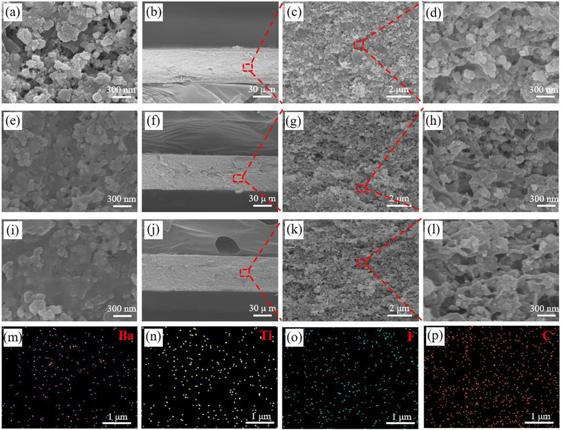 | ||
| Fig. 3 SEM analysis of the composite membrane. Surface (a) and cross section (b–d) of the unpressed CNF/PVDF/0CNF-BaTiO3 composite membrane. Surface (e) and cross section (f–h) of the unpressed CNF/PVDF/10CNF-BaTiO3 composite membrane, as well as its hot-pressed surface (i) and cross section (j–l). (m–p) EDS of cross section of hot-pressed CNF/PVDF/10CNF-BaTiO3 composite membrane based on (k). | ||
It can be observed in the cross section image (Fig. 3b–d, f–h and j–l) that the composite membranes have a significantly layered stack structure, which became similar fiber-crosslinked structures after hot pressing. In the magnified cross-section image of that with CNF-BaTiO3, obvious gap exists before hot pressing (Fig. 3h), which were also retained to a certain degree after hot pressing (Fig. 3l). The content of hybrid BaTiO3 particle (50 wt%) in the composite membrane was high, and the PVDF fused in the hot-pressing process could not completely fill the gaps among the particles, thus forming slight pores. The elemental analysis at the cross section of the piezoelectric composite membrane (Fig. 3m–p and S2d†) further demonstrated that CNF, PVDF and CNF-BaTiO3 were evenly distributed in the composite membrane.
As shown in Fig. 4a, the Bragg reflection of the (100), (110), (111) and (200) crystal faces of BaTiO3 appear in the composite membrane, while that of PVDF is very weak (Fig. 4b), which can be attributed to the combination of BaTiO3 and presence of CNF. After hot pressing, the characteristic diffraction peak at 21.9° of CNFs decreased obviously (Fig. 4c), while the absorption peak of BaTiO3 increased. According to the FTIR analysis, as shown in Fig. 4d and e, the characteristic absorption peaks of the α-phase of PVDF appeared at 762 cm−1 and 799 cm−1 for the hot-pressed composite membrane, while the characteristic peaks of the β-phase of PVDF were located at 847 cm−1, 876 cm−1, and 1284 cm−1 for the hot-pressed composite membrane. In the case of the unpressed composite membrane, the characteristic absorption peaks of the α-phase of PVDF were found at 761 cm−1 and 795 cm−1, as well as the characteristic peaks at 842 cm−1, 877 cm−1, and 1280 cm−1 for the β phase.50,51 By contrast, the ratio of β phase to α phase in the composite membrane after hot pressing increased.
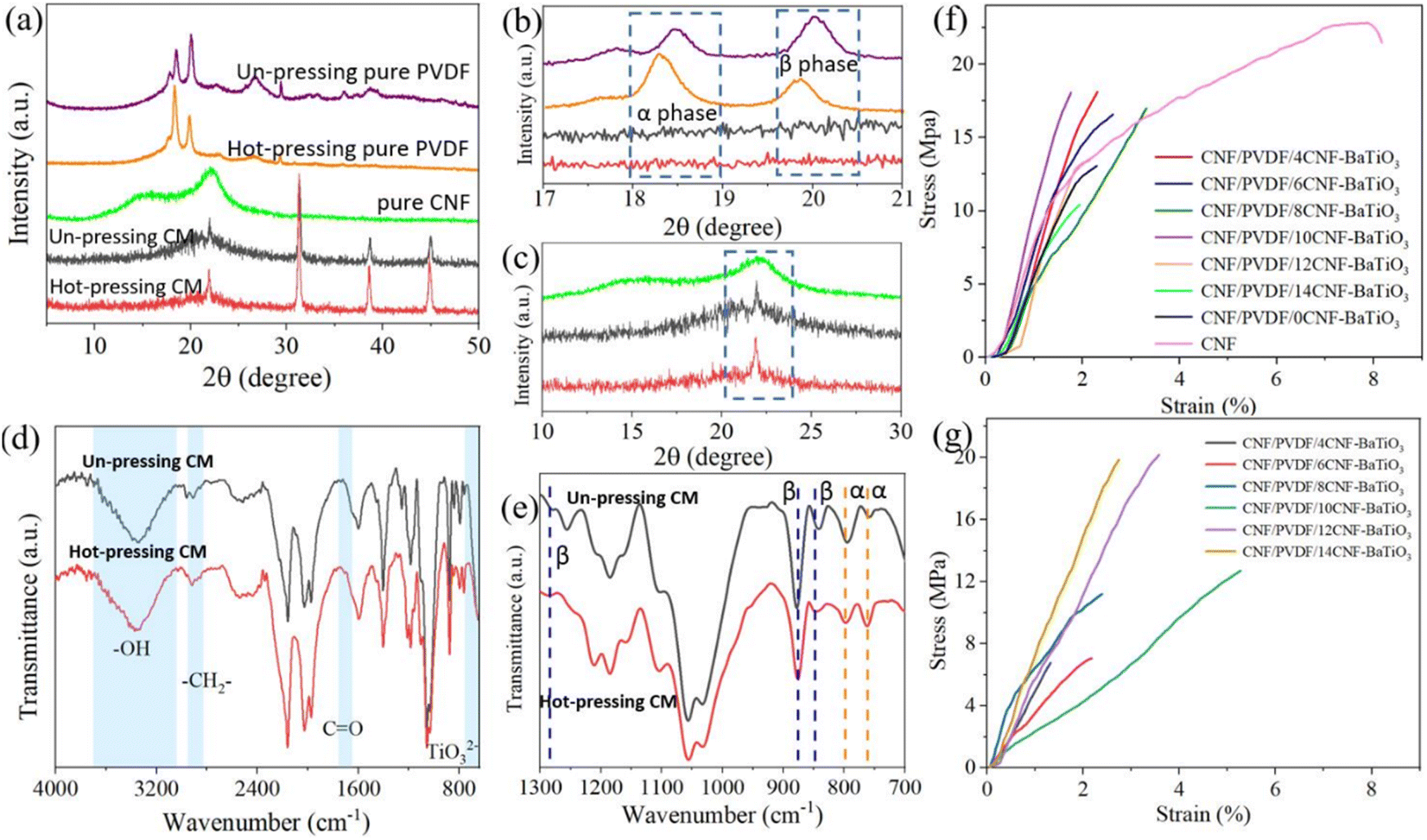 | ||
| Fig. 4 (a–c) XRD analysis of pure CNF membrane, PVDF membrane and CNF/PVDF/10CNF-BaTiO3 composite membrane (CM) before and after hot pressing. (d and e) FTIR analysis of CNF/PVDF/10CNF-BaTiO3 composite membrane (CM) before and after hot pressing. Stress–strain of (f) unpressed composite membranes and (g) hot-pressed composite membranes. | ||
According to the tensile performance of the CNF/PVDF/CNF-BaTiO3 piezoelectric composite membrane, as shown in Fig. 4f and Table S3,† the tensile strength of the pure CNF membrane is 24.98 ± 4.17 MPa with the elongation at break of 10.13 ± 3.18% and Young's modulus of 873.39 ± 260.25 MPa. These values for the piezoelectric composite membranes prepared using various CNF-BaTiO3 without hot pressing were 22.54 MPa, 3.46%, and 1130.30 MPa, respectively. There is little difference in the tensile performance of the various composite membranes prepared using different contents of NaClO. Among them, the CNF/PVDF/10CNF-BaTiO3 composite membrane exhibited considerable tensile strength of 18.61 ± 3.75 MPa and elongation at break of 3.06 ± 1.33%. Combined with the particle size and FTIR analysis, it can be seen that the structure of the composite membrane is denser because the particle size of CNF-BaTiO3 was relatively small and its –OH defect was less due to the assisted synthesis with CNFs, which is conducive to the interface bonding. Compared with that of the composite membrane containing the synthesized BaTiO3 without CNFs, the tensile strength was slightly enhanced with a considerable elongation at break. This confirms that the assistance of CNF elevated the surface activity on the synthesized CNF-BaTiO3, which contributes to the interface bonding of CNF-BaTiO3 to CNF and PVDF.
After hot pressing, the tensile performance of the composite membrane, as shown in Fig. 4g and Table S4,† gradually increased with an increase in the oxidation degree of the CNFs, resulting in the construction of a network gluing structure among the particles (as seen in Fig. 3l). The tensile performance reached the highest at 14 mmol g−1 with the tensile strength of 18.32 ± 3.31 MPa, as well as the higher elongation at break of 4.66 ± 1.32% than that of the unpressed composite membrane, indicating its enhanced flexibility. However, when the oxidation level of CNFs was low, the tensile strength decreased by more than 50% relative to the unpressed composite membrane, which may be caused by the large holes formed in the compressed composite membrane (Fig. S2e and f†).
Piezoelectric performance and application
A flexible PEG (Fig. 5a) was assembled based on the structure shown in Fig. 1 and 5b. The piezoelectric constant can also directly reflect the piezoelectric performance. The longitudinal piezoelectric constant (d33) of the PEG is shown in Fig. 5c and Table S5.† The constant increased with an increase in the oxidation degree of CNFs, and then decreased slightly after 10CNF. Among them, the PEG made using the CNF/PVDF/10CNF-BaTiO3 composite membrane showed the maximum d33 with a value of 5.25 ± 1.04 pC N−1 although it has a small thickness as low as 0.098 ± 0.011 mm (shown in Table S5†) and flexibility. However, after it was hot-pressed, the constant decreased to a certain degree due the formed large holes in the structure (Table S6†). The d33 is comparable to that of the published PVDF/BaTiO3/CNT piezoelectric energy harvesters52 and BaTiO3/PVDF piezocomposites,53 while a lower PVDF content of 20 wt% and slightly higher content of CNFs of 30 wt% were employed in our work. | ||
| Fig. 5 Piezoelectric performance of the PEG. (a) Appearance and flexibility display of PEG, (b) schematic structure of the PEG and sensor and its piezoelectric mechanism, and (c) piezoelectric constant (d33) of PEGs with the unpressed CNF/PVDF/CNF-BaTiO3 composite membranes. (d) ISC and (e) VOC of the PEG with the unpressed CNF/PVDF/CNF-BaTiO3 composite membrane, (g) ISC and (h) VOC of the PEG with hot-pressed CNF/PVDF/CNF-BaTiO3 composite membrane. Test of the PEG with unpressed CNF/PVDF/10CNF-BaTiO3 composite membrane, (f and i) the long-term cycling test with the output of VOC, (j) charging 1 μF capacitor with bridge rectifier circuit, and (k) powered lighting-emitting diode. | ||
Moreover, the piezoelectric output performance of the PEGs prepared using BaTiO3 synthesized with the assistance of CNFs with different oxidation degrees was measured under repeated impact compression test with the maximum force of 40 N at the frequency of 2.2 Hz (Video S1†) using a charge acquisition system, which was exhibited in our previous work,54 and the output is shown in Fig. 5d, e, g, and h. The test results show that all samples demonstrated typical piezoelectric properties under periodic external force. Initially, when there was no impact or vibration on the PEG, there was no piezoelectric output because its electric dipoles randomly oscillated within a degree of their respective alignment axes, maintaining a macroscopic equilibrium state in the composite membrane. When the PEG was subjected to a vertical mechanical impact, which made it compressed, a potential difference was formed between the two electrodes, resulting in the flow of electrons between the two electrodes, and thereby a positive signal was observed. Conversely, when the impact force disappeared, the deformation of the PEG was restored and a negative electrical signal could be detected. Obviously, the output performance of the PEGs with CNF-BaTiO3 was better than that of the PEG with the pure CNF membrane. With an increase in the oxidation degree of CNFs, the output signal strength of the PEG increased firstly, and then decreased, among which the CNF/PVDF/10CNF-BaTiO3 PEG exhibited the highest output with the VOC of 3.6 V and ISC of 200 nA. It can be found that the changing trend of the d33 of the PEGs is consistent with the output results, as shown in Fig. 5d and e. The functional groups of –COO− on the CNF molecular chains serve as nucleation sites for the growth of the BaTiO3 NPs,33 and then the dispersed BaTiO3/CNFs can support the growth of BaTiO3. Simultaneously, the existence of CNFs also limited the growth of BaTiO3. As the dosage of NaClO increased, the prepared CNFs contained more –COO− groups, while the molecular chain length decreased. The output current value increased gradually, and then decreased, which reached the maximum value at 10CNF. It is possible that the BaTiO3 prepared with 10CNF had fewer surface defects and agglomeration, and thus it exhibited better piezoelectric property.
After hot pressing, the output signal changed, and the PEG assembled by using the composite membrane incorporating CNFs with a low oxidation degree showed an increasing trend, while that of the PEG assembled using CNFs with a high oxidation degree did not increase and exhibited a decreasing trend. Among them, the PEG with 4CNF-BaTiO3-based composite membrane exhibited the largest increasing trend. The existing slight difference in the peak value may be due to the difference in strain rate during extrusion or release. The asymmetric positive peak value and negative peak value can be caused by external force during extrusion.40 The specific mechanism for its piezoelectric performance can be seen in Fig. 5a. The PEG remains balanced in the absence of external force, and when mechanical stress was applied, the dipoles in the PEG rearranged and generated a piezoelectric potential between the top and bottom electrodes. The instantaneous internal potential then moved the electrons through an external circuit to neutralize the electric field generated by the substituted dipole. When the PEG was not stressed, the piezoelectric potential disappeared and the opposite built-in potential in the circuit built up simultaneously. Consequently, the electrons flowed back in the opposite direction.55
Subsequently, the unpressed CNF/PVDF/10CNF-BaTiO3 PEG was applied to further explore its potential in actual sensing and energy harvesting application. Fig. 5f and i show the long-term test results of the CNF/PVDF/10CNF-BaTiO3 PEG, where its output performance was normal even in the 1300 cycles after being stable, displaying its good durability. It also showed a gradually increasing trend of VOC from 4 V to 6 V in 500 s. The CNF/PVDF/10CNF-BaTiO3 PEG was connected to a rectifier bridge to charge a 1 μF capacitor (Fig. 5j). Under the exciting force of 40 N at the frequency of 2.2 Hz, the voltage of the capacitor could be charged to reach 3.66 V in 500 s, which is comparable to that of a previously reported cellulose-based generator.56 In addition, the PEG could power a light-emitting diode, as shown in Fig. 5k and Video S2.†
The piezoelectric sensing performance of the PEG (as a sensor) was further explored. As shown in Fig. 6a and b, a polytetrafluoroethylene (PTFE) film was placed on a subplate to avoid the triboelectricity effect, on which the sensor was fixed with PI insulating tape. Then an iron block with a weight of 150 g was dropped vertically from different heights, and the recorded piezoelectric output VOC and ISC are shown in Fig. 6c and d, respectively. The output signal strength was proportional to the stress, where the maximum output VOC and ISC of the sensor could reach as high as 4.5 V and 0.7 μA, respectively, under the stress stimulation of about 20 kPa by the block. Moreover, Fig. 6e shows the piezoelectric signal generated by vertically dropping iron blocks with different masses from a height of 4 cm on the composite membrane sensor, also displaying a high ISC of 0.6 μA under stimulation by a block with the light weight of 6 g. Thus, these results prove that the composite membrane exhibited a considerable sensing performance with high sensitivity, and even captured weak mechanical energy.
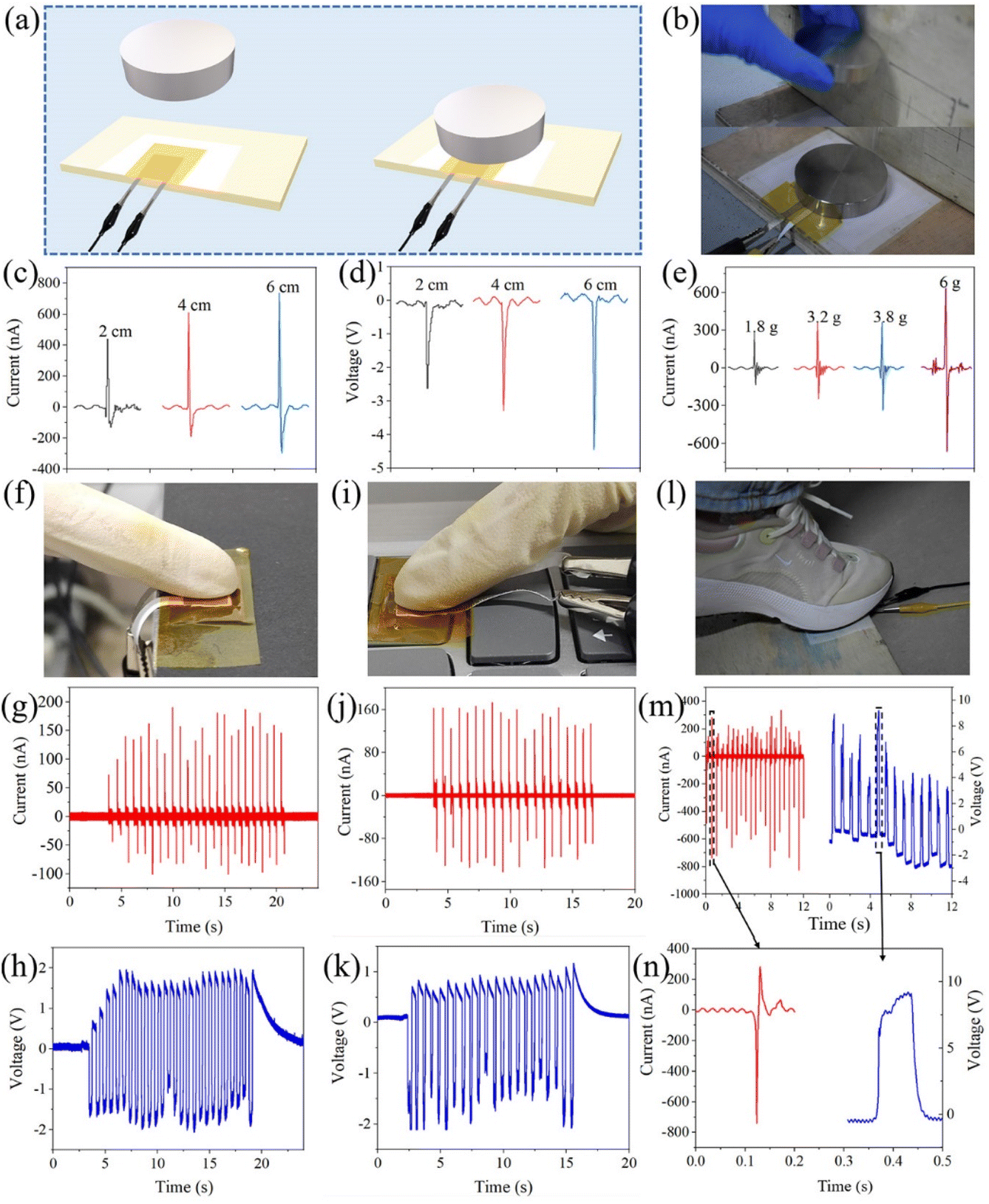 | ||
| Fig. 6 (a) Schematic diagram and (b) actual image of the iron drop test. (c) ISC and (d) VOC of CNF/PVDF/10CNF-BaTiO3 PEG knocked by iron block dropping form different heights and (e) ISC of that knocked by an iron block with different weights dropping from 4 cm. (f) Schematic diagram of the finger pressing test on the experiment table, (g) ISC, and (h) VOC. (i) Schematic diagram of finger pressing test on the keyboard, (j) ISC, and (k) VOC. (l) Schematic diagram for the foot stepping test, (m and n) ISC and VOC. | ||
As shown in Fig. 6f–h, when the PEG was repeatedly pressed by a finger (Video S3†), the output VOC of about 2 V and ISC of 180 nA were generated, which are comparable to the results in a similar work.57 Then, the PEG was transferred to a keyboard (Fig. 6i–k) and it could generate an output of about 1–2 V and 170 nA under the knock by a finger (Video S4†), similar to that in Fig. 6f–h. In addition, the PEG was fixed on the ground to simulate the energy harvesting from human movement (Fig. 6l–n), and then it was stepped on with a foot, exhibiting a higher output with VOC of about 9 V and ISC of 739 nA, which are comparable to the results of similar work.58 Of course, the output data fluctuated slightly during the test, which is due to the fact that the loading magnitude and point of the force cannot be ensured to be completely consistent.
Conclusions
In this work, CNFs were endowed with higher piezoelectric properties and employed to synthesize hybrid BaTiO3 with a uniform particle size, high crystallinity and active surface via low-temperature hydrothermal synthesis. The TEMPO-oxidized CNFs with abundant oxygen-containing groups on their surface acted as even and nanoscale nucleation sites for the synthesis of BaTiO3, as well as contributed to the activity on its surface. The synthesized CNF-BaiTO3 was incorporated in CNFs and PVDF to fabricate flexible composite piezoelectric membranes, which were finally assembled as a PEG and sensor. The modification by CNFs enhanced the combination of CNF-BaiTO3 with CNF in the composite membrane, thus elevating its flexibility with the piezoelectric substrate of CNF and PVDF. In the composite membrane, there were fibrous connections of PVDF between particles to construct a distinct network bonding structure, which was further enhanced with the assistance of the CNF substrate. The piezoelectric properties were improved by adding CNF-BaiTO3 to the composite membrane. Consequently, the CNF/PVDF/10CNF-BaTiO3 PEG generated a VOC of 3.6 V and ISC of 211 nA. Its longitudinal piezoelectric constant (d33) was 5.25 ± 1.04 pC N−1. It also exhibited high sensitivity to human movement, such as high output with a VOC of about 9 V and ISC of 739 nA when stepped on by a foot. Thus, it can be feasibly employed as a sensor and energy collector. The proposed simple low-temperature hydrothermal synthesis with the assistance of TEMPO-oxidized CNFs has potential significance for practical applications and can act as a reference for the enhancement of other BaTiO3-based PEGs, as well as the piezoelectric functionalization of CNFs.Author contributions
Meilin Li: conceptualization, writing – original draft, investigation, methodology, data curation, formal analysis, writing – review & editing, visualization. Bei Jiang: formal analysis, investigation, investigation. Shuoang Cao: formal analysis, investigation, investigation. Xinyi Song: formal analysis, investigation. Yuanqiao Zhang: formal analysis, investigation. Lijun Huang: methodology, software. Quanping Yuan: conceptualization, methodology, writing-original draft, investigation, writing – review & editing, supervision, project administration, funding acquisition.Conflicts of interest
The authors declare no competing financial interests.Acknowledgements
This work was supported by the National Natural Science Foundation of China (No. 32071695).Notes and references
- S. K. Karan, S. Maiti, A. K. Agrawal, A. K. Das, A. Maitra, S. Paria, A. Bera, R. Bera, L. Halder, A. K. Mishra, J. K. Kim and B. B. Khatua, Nano Energy, 2019, 59, 169–183 CrossRef CAS.
- S. Siddiqui, H. B. Lee, D.-I. Kim, L. T. Duy, A. Hanif and N.-E. Lee, Adv. Energy Mater., 2017, 8, 1701520 CrossRef.
- T. Gao, J. Liao, J. Wang, Y. Qiu, Q. Yang, M. Zhang, Y. Zhao, L. Qin, H. Xue, Z. Xiong, L. Chen and Q.-M. Wang, J. Mater. Chem. A, 2015, 3, 9965–9971 RSC.
- W.-B. Li, D. Zhou, L.-X. Pang, R. Xu and H.-H. Guo, J. Mater. Chem. A, 2017, 5, 19607–19612 RSC.
- C. K. Jeong, I. Kim, K.-I. Park, M. H. Oh, H. Paik, G.-T. Hwang, K. No, Y. S. Nam and K. J. Lee, ACS Nano, 2013, 7, 11016–11025 CrossRef CAS PubMed.
- J. Yan, Y. Han, S. Xia, X. Wang, Y. Zhang, J. Yu and B. Ding, Adv. Funct. Mater., 2019, 29, 1907919 CrossRef CAS.
- Z. Wang, J. Cheng, R. Hu, X. Yuan, Z. Yu, X. Xu, F. Wang, J. Dong, R. Gong, S. Dong and H. Wang, J. Mater. Chem. A, 2021, 9, 26767–26776 RSC.
- N. Meng, R. Mao, W. Tu, K. Odolczyk, Q. Zhang, E. Bilotti and M.-J. Reece, Polymer, 2017, 121, 88–96 CrossRef CAS.
- J. Jiang, S. Tu, R. Fu, J. Li, F. Hu, B. Yan, Y. Gu and S. Chen, ACS Appl. Mater. Inter., 2020, 12, 33989–33998 CrossRef CAS PubMed.
- G. Zhang, Q. Liao, Z. Zhang, Q. Liang, Y. Zhao, X. Zheng and Y. Zhang, Adv. Sci., 2016, 3, 1500257 CrossRef PubMed.
- J. R. G. Navarro, J. Rostami, A. Ahlinder, J. B. Mietner, D. Bernin, B. Saake and U. Edlund, Biomacromolecules, 2020, 21, 1952–1961 CrossRef CAS PubMed.
- S. K. Mahadeva, K. Walus and B. Stoeber, ACS Appl. Mater. Inter., 2014, 6, 7547–7553 CrossRef CAS PubMed.
- X. Yang and W. Daoud, J. Mater. Chem. A, 2017, 5, 9113–9121 RSC.
- Y. Feng, L. Liu, P. Chen, M. Bo, J. Xie and Q. Deng, Surf. Interfaces, 2022, 31, 102060 CrossRef CAS.
- U. Yaqoob, A. S. M. I. Uddin and G.-S. Chung, Appl. Surf. Sci., 2017, 405, 420–426 CrossRef CAS.
- Y. Deng, Y. Zhang, Y. Xiang, G. Wang and H. Xu, J. Mater. Chem., 2009, 19, 2058–2061 RSC.
- T. Kavinkumar, P. Senthilkumar, S. Dhanuskodi and S. Manivannan, J. Eur. Ceram. Soc., 2017, 37, 1401–1409 CrossRef CAS.
- Y. Yang, H. Pan, G. Xie, Y. Jiang, C. Chen, Y. Su, Y. Wang and H. Tai, Sens. Actuators, A, 2020, 301, 111789 CrossRef CAS.
- J. Yang, X. Xie, Z. He, Y. Lu, X. Qi and Y. Wang, Chem. Eng. J., 2019, 355, 137–149 CrossRef CAS.
- Prateek, V. K. Thakur and R. K. Gupta, Chem. Rev., 2016, 116, 4260–4317 CrossRef CAS PubMed.
- S.-F. Liu, I. R. Abothu and S. Komarneni, Mater. Lett., 1999, 38, 344–350 CrossRef CAS.
- A. K. Maurice and R. C. Buchanan, Ferroelectrics, 1987, 74, 61–75 CrossRef CAS.
- J. E. Jeon, H. S. Han, K. R. Park, Y. R. Hong, K. B. Shim and S. Mhin, Ceram. Int., 2017, 44, 1420–1424 CrossRef.
- N. Suzuki, X. Jiang, R. R. Salunkhe, M. Osada and Y. Yamauchi, Chem.–Eur. J., 2014, 20, 11283–11286 CrossRef CAS PubMed.
- F. Maxim, P. Ferreira, P. M. Vilarinho and I. Reaney, Cryst. Growth Des., 2008, 8, 3309–3315 CrossRef CAS.
- A. V. Zanfir, G. Voicu, S. I. Jinga, E. Vasile and V. Ionita, Ceram. Int., 2016, 42, 1672–1678 CrossRef CAS.
- T. Kubo, M. Hogiri, H. Kagata and A. Nakahira, J. Am. Ceram. Soc., 2009, 92, S172–S176 CrossRef CAS.
- J. Ortiz-Landeros, C. Gómez-Yáñez, R. López-Juárez, I. Dávalos-Velasco and H. Pfeiffer, J. Adv. Ceram., 2012, 1, 204–220 CrossRef CAS.
- Y. Ma, E. Vileno, S. L. Suib and P. K. Dutta, Chem. Mater., 1997, 9, 3023–3031 CrossRef CAS.
- M. Özen, M. Mertens, F. Snijkers and P. Cool, Ceram. Int., 2016, 42, 10967–10975 CrossRef.
- G. J. Choi, H. S. Kim and Y. S. Cho, Mater. Lett., 1999, 41, 122–127 CrossRef CAS.
- Q. Huang and L. Gao, J. Mater. Chem., 2004, 14, 2536–2541 RSC.
- J. K. Han, D. S. Song, Y. R. Lim, W. Song, S. Myung, S. S. Lee, K.-S. An, H.-K. Jung, S. Santucci, V. Esposito and J. Lima, Appl. Surf. Sci., 2021, 538, 147962 CrossRef CAS.
- Y. Li, H. Zhu, F. Shen, J. Wan, S. Lacey, Z. Fang, H. Dai and L. Hu, Nano Energy, 2015, 13, 346–354 CrossRef CAS.
- J. Luo, N. Semenikhin, H. Chang, R. J. Moon and S. Kumar, Carbohydr. Polym., 2018, 181, 247–255 CrossRef CAS PubMed.
- J. S. Kim and D. H. Kim, Elastomers Compos., 2020, 55, 176–183 CAS.
- T. Saito, S. Kimura, Y. Nishiyama and A. Isogai, Biomacromolecules, 2007, 8, 2485–2491 CrossRef CAS PubMed.
- H. Gullapalli, V. S. M. Vemuru, A. Kumar, A. Botello-Mendez, R. Vajtai, M. Terrones, S. Nagarajaiah and P. M. Ajayan, Small, 2010, 6, 1641–1646 CrossRef CAS PubMed.
- S. Liu, K. Yao, B. Wang and M. G. Ma, Iran. Polym. J., 2017, 26, 681–691 CrossRef CAS.
- K. Shi, X. Huang, B. Suna, Z. Wu, J. He and P. Jiang, Nano Energy, 2019, 57, 450–458 CrossRef CAS.
- H. S. Potdar, S. B. Deshpande, A. S. Deshpande, Y. B. Khollam, A. J. Patil, S. D. Pradhan and S. K. Date, Int. J. Inorg. Mater., 2001, 3, 613–623 CrossRef CAS.
- Y. Zhuang, F. Li, G. Yang, Z. Xu, J. Li, B. Fu, Y. Yang and S. Zhang, J. Am. Ceram. Soc., 2014, 97, 2725–2730 CrossRef CAS.
- B. Dudem, L. K. Bharat, H. Patnam, A. R. Mulea and J. S. Yu, J. Mater. Chem. A, 2018, 6, 16101–16110 RSC.
- F. Sayed, D. C. Joshi, G. Kotnana, D. Peddis, T. Sarkar and R. Mathieu, Inorg. Chim. Acta, 2021, 520, 120313 CrossRef CAS.
- M. V. Petrovic, F. Cordero, E. Mercadelli, E. Brunengo, N. Ilic, C. Galassi, Z. Despotovic, J. Bobic, A. Dzunuzovic, P. Stagnaro, G. Canu and F. Craciun, J. Alloys Compd., 2021, 884, 161071 CrossRef.
- T. Kavinkumar, P. Senthilkumar, S. Dhanuskodi and S. Manivannan, J. Eur. Ceram. Soc., 2017, 37, 1401–1409 CrossRef CAS.
- C. Zhang, Y. Yin, Q. Yang, Z. Shi, G.-H. Hu and C. Xiong, ACS Sustainable Chem. Eng., 2019, 7, 10641–10648 CrossRef CAS.
- J. Li, K. Inukai, Y. Takahashi and W. Shin, J. Asian Ceram. Soc., 2016, 4, 394–402 CrossRef.
- Y. B. Pottathara, V. Bobnar, M. Finšgar, Y. Grohens, S. Thomas and V. Kokol, Polymer, 2018, 147, 260–270 CrossRef CAS.
- C. Shuai, G. Liu, Y. Yang, F. Qi, S. Peng, W. Yang, C. He, G. Wang and G. Qian, Nano Energy, 2020, 74, 104825 CrossRef CAS.
- K. Shi, B. Chai, H. Zou, P. Shen, B. Sun, P. Jiang, Z. Shi and X. Huang, Nano Energy, 2021, 80, 105515 CrossRef CAS.
- C. Yang, S. Song, F. Chen and N. Chen, ACS Appl. Mater. Interfaces, 2021, 13, 41723–41734 CrossRef CAS PubMed.
- J. Defebvin, S. Barrau, J. Lyskawa, P. Woisel and J. M. Lefebvre, Compos. Sci. Technol., 2017, 147, 16–21 CrossRef CAS.
- S. Cao, H. Zou, B. Jiang, M. Li and Q. Yuan, Nano Energy, 2022, 102, 107635 CrossRef CAS.
- H. Zhang, C. K. Jeong, Z. Shen, J. Wang, H. Sun, Z. Jian, W. Chen and Y. Zhang, Composites, Part B, 2022, 236, 109813 CrossRef CAS.
- Z. Sun, L. Yang, S. Liu, J. Zhao, Z. Hu and W. Song, Sensors, 2020, 20, 506 CrossRef CAS PubMed.
- H. J. Oh, D.-K. Kim, Y. C. Choi, S.-J. Lim, J. B. Jeong, J. H. Ko, W.-G. Hahm, S.-W. Kim, Y. Lee, H. Kim and B. J. Yeang, Sci. Rep., 2020, 10, 16339 CrossRef CAS PubMed.
- W. Guo, C. Tan, K. Shi, J. Li, X.-X. Wang, B. Sun, X. Huang, Y.-Z. Long and P. Jiang, Nanoscale, 2018, 10, 17751–17760 RSC.
Footnote |
| † Electronic supplementary information (ESI) available. See DOI: https://doi.org/10.1039/d3ra00604b |
| This journal is © The Royal Society of Chemistry 2023 |