
 Open Access Article
 This Open Access Article is licensed under a Creative Commons Attribution-Non Commercial 3.0 Unported Licence
Influence of deposition temperature on microstructure and gas-barrier properties of Al2O3 prepared by plasma-enhanced atomic layer deposition on a polycarbonate substrate
Yueqing Ren *,
Xiaojie Sun,
Lanlan Chen,
Hui Wei,
Bo Feng and
Jingyun Chen
*,
Xiaojie Sun,
Lanlan Chen,
Hui Wei,
Bo Feng and
Jingyun Chen
National Institute of Clean-and-Low-Carbon Energy, Beijing 102211, China. E-mail: yueqing.ren@chnenergy.com.cn
First published on 25th January 2023
Abstract
We prepared polymer-based encapsulation films by plasma-enhanced atomic layer deposition (PEALD) of Al2O3 film on a polycarbonate (PC) substrate at 80–160 °C to fabricate Al2O3/PC barrier films. The thermal and dynamic mechanical properties of the PC substrate, the structural evolution of PEALD Al2O3 films, the optical transmission, surface morphology, and gas-barrier properties of Al2O3/PC film are all studied in this work as a function of temperature. The glass transition temperature Tg of the PC substrate is about 140 °C, and the coefficient of thermal expansion increases significantly when the temperature exceeds Tg. Increasing the deposition temperature from 80 to 160 °C for Al2O3 film deposited over 300 cycles increases the density from 3.24 to 3.45 g cm−3, decreases the thickness from 44 to 40 nm, and decreases the O/Al content ratio from 1.525 to 1.406. Al2O3/PC films deposited at 80–120 °C have no surface cracks, whereas surface cracks appear in samples deposited near or above 140 °C. Upon increasing the deposition temperature, the water vapor transmission rate (WVTR) and oxygen transmission rate (OTR) of Al2O3/PC films decrease significantly at temperatures below Tg, and then increase at temperatures near to or above Tg due to cracks in the films. The optimal deposition temperature is 120 °C, and the minimum WVTR and OTR of Al2O3/PC film are 0.00132 g per (m2 24 h) and 0.11 cm3 per (m2 24 h 0.1 MPa), respectively. The gas-barrier properties of the Al2O3/PC films are attributed to both the densification of the Al2O3 film and the cracks, which are caused by the shrinkage of the PC substrate.
1 Introduction
Polymer-based encapsulation films with attractive gas-barrier properties are critical for maximizing the lifetime of flexible electronic devices (e.g., flexible solar cells and organic light-emitting diodes).1–4 Estimates indicate that encapsulation films for solar cells allow around 10−3 g per (m2 24 h) of water vapor to pass through and thereby affect the sensitive underlying electronic components.5,6 For organic light-emitting diodes, the WVTR requirements are even more stringent [in the range of 1 × 10⁻⁶ g per (m2 24 h)].7,8Atomic layer deposition (ALD) is a technique for fabricating ultrathin films of inorganic materials.9–11 An ALD cycle comprises alternating pulses of precursor and oxidant accompanied by purging with an inert gas. The precursor and oxidant pulses are separately injected into the reaction chamber, and the by-products and excess precursor are purged by the inert gas. The self-limiting chemical reactions of ALD allow the film thickness to be controlled, produce excellent step coverage and conformality, produce uniform films with low defect density over large areas, and create pinhole-free structures, making these reactions widely used to develop barrier films with ultralow-gas permeation.12–16
Al2O3 film prepared by the ALD process is one of the most studied materials because of its significant technological importance.17–19 It has excellent dielectric properties, high passivation,20,21 high thermal and chemical stability22 and strong adhesion to various substrates. Moreover, it is one of the most common and widely reported ALD-produced barrier materials because of its superior barrier properties against gas permeation.13
ALD Al2O3 film also has some limitations, one of which is the high temperatures required for the formation of Al2O3 film, which hinders its application to polymeric substrates.23,24 Most flexible substrates are sensitive to high temperature25,26 and may be damaged if exposed for more than a certain time, so the processing temperature plays a determinant role in the fabrication of inorganic films.24,27 At low ALD temperatures, the reaction may be so slow that it lasts longer than the cycle period, resulting in insufficient conversion of the inorganic film and ultimately an inferior-quality inorganic film.13,22 Therefore, ALD must be done at a temperature that is optimal for polymeric substrates. Thus, the optimum deposition temperature becomes a key parameter for preparing the barrier film.
Polycarbonate (PC) is a highly transparent material with good flexibility and surface smoothness. It is of great interest as a substitute for glass substrates for applications in solar cells and is also widely used in optics and electronics.28–30 The PC glass transition temperature is about 140 °C, which exceeds that of poly(ethylene terephthalate) (70–80 °C)26 and poly(ethylene 2,6-naphthalate) (126 °C) film.14 PC is also highly transparent and its optical purity exceeds 92%.28 These characteristics make PC film a good candidate as a substrate for flexible encapsulation films.
In this work, we use plasma-enhanced ALD to prepare Al2O3 films, with O2 plasma serving as the oxygen source. Oxygen radicals generated by the plasma increase the film reactivity and improve the uniformity of the inorganic materials.31,32 The film properties depend strongly on the film preparation conditions, especially the deposition temperature. Thus, this research strives to determine the correlation between (i) deposition temperature and (ii) the structural evolution of microstructures and the barrier properties of Al2O3/PC films. The temperature dependence of the thermal and dynamic mechanical properties of the PC substrate, the structural evolution of the Al2O3 film, and how the interaction between PC substrate and Al2O3 film affects the optical transmission, surface morphology, water vapor transmission rate (WVTR) and oxygen transmission rate (OTR) are all studied systematically.
2 Experiment
2.1 Materials
LEXAN™ polycarbonate (PC) films 100 μm thick were used as substrates. The PC-film grade was 8010MC. Si wafer substrates were purchased from Zhejiang Lijing Silicon Materials Co., Ltd. Trimethylaluminum (TMA) was purchased from Shanghai Dayuan New Materials Co., Ltd and used as an Al precursor. O2 plasma was used as an O reactant and Ar was used as the carrier and purging gas.2.2 Sample preparation
Si, glass, and PC substrates were used in the study. A Si wafer was used as substrate in the ALD process for X-ray photoelectron spectroscopy (XPS) to avoid contamination of the Al2O3 films with O and C, which are present in PC, during the XPS analysis. Glass served as substrate in the ALD process for X-ray reflectivity (XRR) measurements, and a PC-film substrate was used for other structural analyses. Both the Si and glass substrates were cleaned with deionized water and blow-dried with nitrogen to remove contaminants. The PC film was used directly after tearing off the protective film.All Al2O3/substrate films were deposited under the same conditions except for the substrate temperature, which was varied from 80 to 160 °C. Al2O3 film was deposited over 300 cycles by using a Picosun ALD apparatus. Briefly, each ALD cycle consisted of exposure of the substrate to TMA vapor for 0.1 s, 6 s of N2-purge to remove physisorbed TMA, 26 s exposure to O2 plasma and then 6 s of Ar-purge. The O2 plasma generator operated at 2700 W.
2.3 Measurements and characterisations
The glass transition temperature Tg of the PC film was measured as per the ISO 11357-2:2020 standard. A differential scanning calorimetry thermogram was obtained by using a TA Q2000 instrument under a nitrogen atmosphere. Samples were tested at a heating rate of 20 °C min−1 and the results from the second heating in the range 40–200 °C are reported.Dynamic mechanical analysis (DMA) and thermal mechanical analysis were done with a DMA 242E Artemis instrument. Samples of size 10 × 6 × 0.1 mm3 were mounted in tension mode, and the temperature was ramped from 40 to 170 °C at 1 °C min−1. The DMA test used a dynamic strain of 0.3% and frequencies of 0.1, 1, 10, and 20 Hz. For the thermal mechanical analysis test, the sample was subjected to 6 mN of static force.
The light transmittance of the Al2O3/PC film was measured by using a Shimadzu UV-3600 spectrophotometer in the wavelength range 300–1200 nm. The density and thickness of Al2O3 were determined by XRR measurements done with a Burker D8 Discover system. The elemental analysis was done with an XPS equipped with a conventional Al Kα source. The thickness and refractive index n of Al2O3 were determined by using a UVISEL Plus spectroscopic ellipsometry (SE) instrument in the wavelength range 400–800 nm. Finally, the surface morphology of Al2O3/PC films was imaged by using a Nova NanoSEM 450 scanning electron microscope and a Bruker Dimension ICON atomic force microscope (AFM).
The water vapor transmission rate (WVTR) was measured at 30% and 90% relative humidity. The WVTR of the Al2O3/PC film was measured by using a Mocon AQUATRAN Model 3 instrument, and the WVTR of the PC matrix film was measured by using a Mocon PERMATRAN W model 3/33 instrument. Finally, OTR measurements were done by using a Labthink C130 gas permeability test system at 23 °C and 0% relative humidity.
3 Results and discussion
3.1 Thermal characteristics of PC substrate film
The mobility in the polymeric material is significantly more affected by temperature than that in the inorganic Al2O3 film, with a big change in mobility occurring just below and above the glass transition temperature Tg of the polymer substrate. Fig. 1 shows the differential scanning calorimetry curve from which Tg ≈ 144.0 °C is deduced.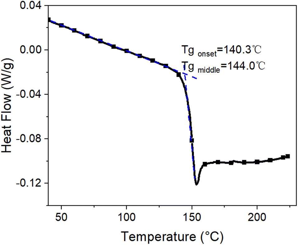 | ||
| Fig. 1 Differential scanning calorimetry curve of PC substrate film. | ||
The temperature dependence of the mobility of the PC molecules is further studied by thermal mechanical analysis and DMA methods. The results are shown in Fig. 2 and Table 1. Fig. 2(a) shows the coefficient of thermal expansion (CTE) of the PC substrate. From 40 to 138 °C, the PC macromolecules are in the glassy state, the CTE increases slightly with increasing temperature from 0.7 × 10⁻⁴ to 0.9 × 10⁻⁴ °C−1 and the change dL in length increases from 0 to 110 μm (about 1.1% strain) for the PC substrate film. As temperature increases from 138 to 150 °C, the PC macromolecules change from the glassy state to the rubbery state, and CTE decreases because the stress caused by shrinkage exceeds that caused by tension. Above 150 °C, the PC macromolecules are in a viscous state and their mobility increases significantly, so the CTE and dL for the PC substrate film increase significantly. A significant transition in the CTE occurs above and below Tg.
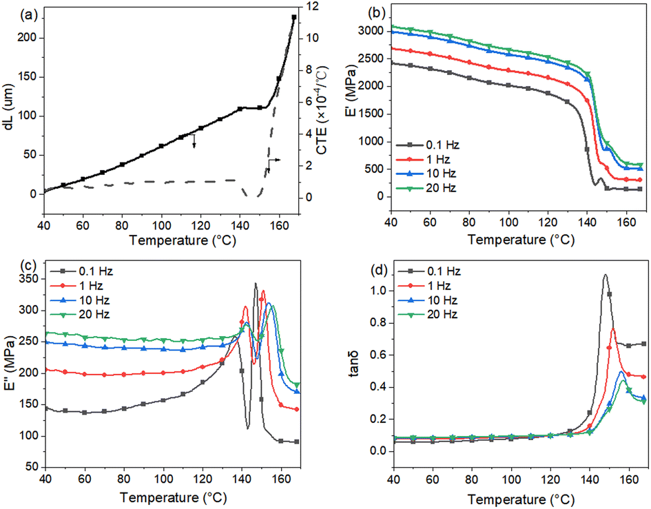 | ||
| Fig. 2 (a) Thermal mechanical analysis data, (b) storage modulus, (c) loss modulus and (d) loss factor of DMA analysis of PC substrate film. | ||
| 0.1 Hz | 1 Hz | 10 Hz | 20 Hz | |
|---|---|---|---|---|
| E′′peak1 (°C) | 136.5 | 142.0 | 142.5 | 142.0 |
| E′′peak2 (°C) | 147.0 | 151.5 | 153.5 | 155.5 |
tan![[thin space (1/6-em)]](https://www.rsc.org/images/entities/char_2009.gif) δ (°C) δ (°C) |
148.0 | 151.5 | 156.0 | 156.5 |
Four frequencies were used in the DMA test. Upon decreasing the frequency from 20 to 0.1 Hz, the loss factor (tanδ) of the PC decreases from 156.5 to 148 °C. The loss modulus E′′ of the PC substrate peaks twice, where E′′peak2 is attributed to the glass transition of PC molecules and E′′peak1 is attributed to the thermal history, for example, hot stretching during PC-film casting. Both E′′ peaks and the storage modulus E′ decrease with decreasing frequency. E′′peak1 ≈ 0.1 Hz at 136.5 °C, indicating that a viscous-nature transition occurs from the glassy state to the glassy state for the PC macromolecules. The mobility of the macromolecules starts increasing and the storage modulus E′ starts decreasing significantly. When the temperature increases to about 160 °C, the PC macromolecules change to a viscous state and the PC mobility increases significantly, which likely causes a server mismatch between the polymer substrate and the inorganic Al2O3 film.
3.2 Structural evolution of Al2O3 film with increasing deposition temperature
The structural evolution of the Al2O3 film was first investigated by XPS. To avoid surface contamination of the samples during XPS measurements, the films were sputtered off from the extreme surface of samples exposed to ambient air under Ar+ sputtering for 60 s. Moreover, we replaced the PC substrate with a Si substrate to avoid any possible contamination by O and C from the PC substrate during the XPS analysis. The XPS data are reported in Fig. 3 and Table 2. With increasing deposition temperature, the O/Al content ratio decreases from 1.525 to 1.406. The C content also decreases, which is attributed to the removal of –CH3, COO and –OH groups.33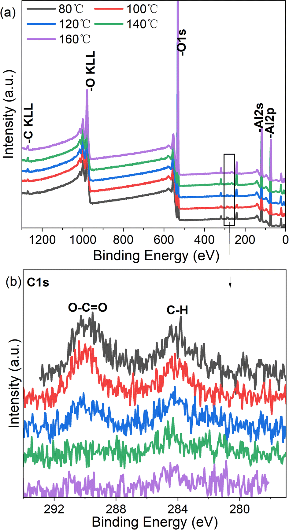 | ||
| Fig. 3 XPS spectra of Al2O3 deposited on Si substrate at different temperatures. | ||
| Temperature (°C) | O (%) | Al (%) | O/Al ratio |
|---|---|---|---|
| 80 | 60.39 | 39.61 | 1.525 |
| 100 | 60.08 | 39.92 | 1.505 |
| 120 | 59.42 | 40.58 | 1.464 |
| 140 | 58.65 | 41.35 | 1.418 |
| 160 | 58.44 | 41.56 | 1.406 |
The effects of deposition temperature on the structural parameters of Al2O3 were further investigated by XRR and SE; (see results in Fig. 4 and Table 3). The density of Al2O3 increases from 3.24 g cm−3 at 80 °C to 3.45 g cm−3 at 160 °C. The thickness of Al2O3 derived by fitting the XRR and SE measurements decreases with increasing deposition temperature. The densification of Al2O3 film with increasing deposition temperature is attributed to the decorporation of the residual O–H,13,32 –CH3 and –COO groups in the Al2O3 films.
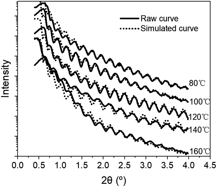 | ||
| Fig. 4 Experimental and simulated XRR curves for samples deposited between 80 and 160 °C. | ||
3.3 Optical properties of Al2O3/PC films
The optical properties of permeation barrier layers are important for fabricating high-efficiency optical devices. The optical transmittance of the PC and Al2O3/PC films were measured by using a UV-visible spectrophotometer, and the results are shown in Fig. 5. The transmittance of PC is greater than that of the Al2O3/PC films. Moreover, the transmittance of the Al2O3/PC films decreases slightly with increasing deposition temperature during ALD. The variations in the transmittance data are primarily caused by the optical reflection, which is related to the refractive index n. For Al2O3 and PC films, n was measured by using a SE instrument, and the results are shown in Fig. 6. For PC, n is lower than that of Al2O3. For Al2O3, n increases with increasing deposition temperature, which may be due to the greater density of Al2O3.20 Light incident at the PC– or Al2O3–air interface is more strongly reflected as n increases, leading to a lower transmittance. Therefore, Al2O3/PC deposited at higher temperatures has lower transmittance.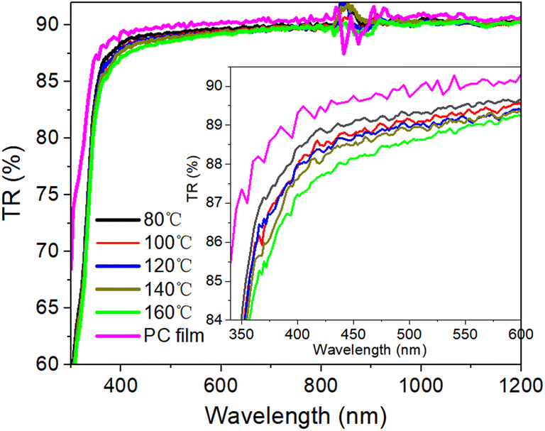 | ||
| Fig. 5 Transmittance rate (TR) of the PC and Al2O3/PC films. | ||
 | ||
| Fig. 6 Refractive index of A2O3 films deposited at different temperature and the PC film. | ||
3.4 Surface morphology of the Al2O3/PC films
We used scanning electron microscopy to image the microstructure of the PC substrate film and the Al2O3/PC films. The results are shown in Fig. 7. The morphology of the PC film and the Al2O3/PC films deposited at 80–120 °C are similar. Cracks appear in the Al2O3/PC films deposited at 140 and 160 °C. When the deposition temperature is below Tg (about 140 °C), the CTE is about 0.7 × 10⁻⁴ to 0.9 × 10⁻⁴ °C−1 and dL < 110 μm. The thermal expansion of the PC film causes a strain of about 1.1% at 140 °C, which exceeds the crack onset strain (0.95% ± 0.17%) for 40 nm-thick Al2O3 films.34 Moreover, the CTE exceeds 1.9 × 10⁻⁴ °C−1 at temperatures above Tg (ref. 35) and increases significantly with increasing temperature. The linear expansion coefficient of Al2O3 is about 6–10 × 10−6 °C−1.36 Thus, a serious mismatch in the CTE occurs between the Al2O3 ALD film and the PC substrate when the deposition temperature exceeds Tg of the PC substrate, which leads to residual thermal stress and cracks, as depicted schematically in Fig. 8. | ||
| Fig. 7 Scanning electron microscopy images of PC and Al2O3/PC films. | ||
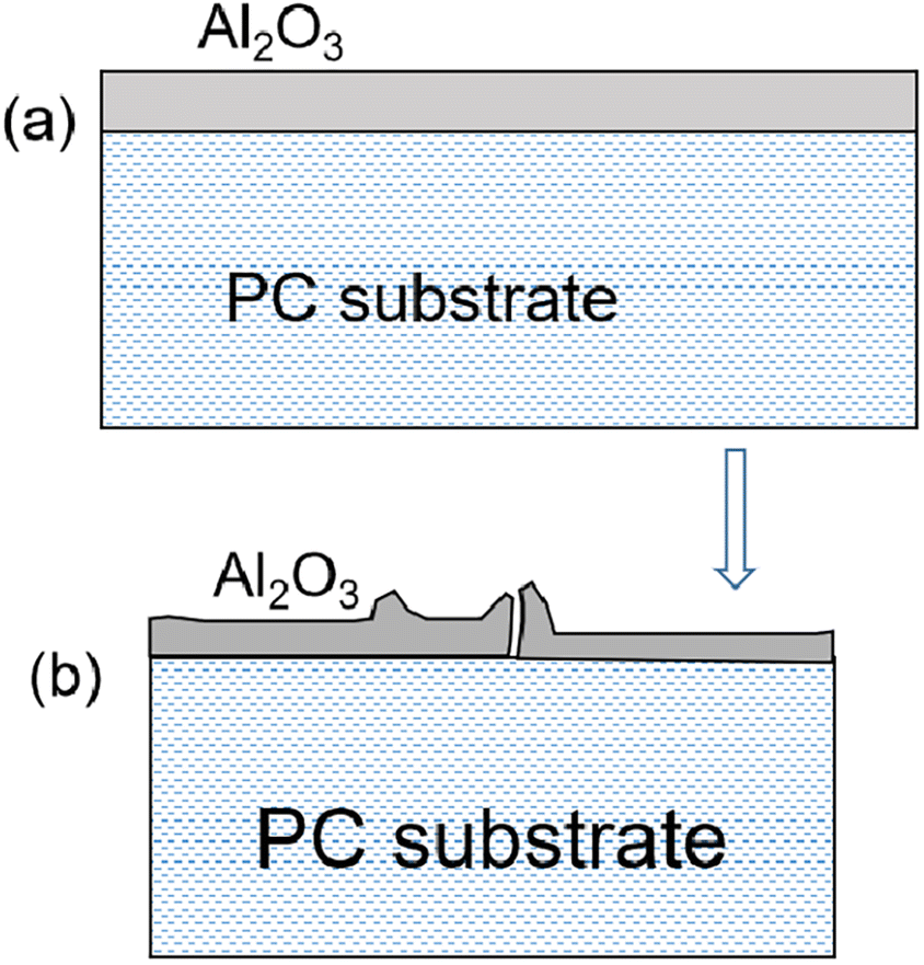 | ||
| Fig. 8 (a) Al2O3 ALD film deposited at elevated temperature on PC substrate. (b) Al2O3 film buckles upon cooling from deposition temperature to room temperature. | ||
The surface roughness of the PC and Al2O3/PC films was measured by using an AFM in a 5 × 5 μm2 area. The results appear in Fig. 9 and Table 4. Ra and Rq of the Al2O3/PC film are slightly lower than those of the PC films, except for the Al2O3/PC film deposited at 160 °C. Moreover, upon increasing the deposition temperature from 80 to 120 °C, Ra and Rq of the Al2O3/PC films decrease slightly, which is attributed to the greater density of Al2O3. Ra and Rq increase with increasing deposition temperature from 120 to 160 °C. A crack appears in the AFM graph of the Al2O3/PC film deposited at 160 °C, which increases Ra and Rq. The increase of Ra and Rq between 120 and 160 °C is likely due to the large increase in the CTE of the PC film caused by the glass transition of the PC substrate. When the temperature increases from 120 to 160 °C, the PC macromolecules transfer from the rubbery state to the viscous state and the change dL in length of the PC substrate increases significantly and exceeds the crack-onset strain of the Al2O3 film. Therefore, mini cracks appear in the Al2O3 film, which increase the surface roughness.
 | ||
| Fig. 9 AFM surface images of randomly selected 5 × 5 μm2 areas of PC and Al2O3/PC films. | ||
| Roughness | PC film | Al2O3/PC film | ||||
|---|---|---|---|---|---|---|
| 80 °C | 100 °C | 120 °C | 140 °C | 160 °C | ||
| Ra (nm) | 0.681 | 0.379 | 0.317 | 0.241 | 0.251 | 4.51 |
| Rq (nm) | 0.878 | 0.694 | 0.483 | 0.307 | 0.318 | 7.91 |
3.5 Barrier properties of Al2O3/PC films
To investigate how deposition temperature affects the gas barrier properties, the WVTR and OTR of the Al2O3/PC films were measured, and the results appear in Fig. 10. For the PC substrate film, the WVTR and OTR are 33.41 g per (m2 24 h) and 482.95 cm3 per (m2 24 h 0.1 MPa), respectively. After deposition of Al2O3, the WVTR and OTR decrease significantly. The WVTR and OTR of the Al2O3/PC films decrease between 80 and 120 °C, which is attributed to the increase in Al2O3 mass density. The WVTR and OTR increase between 120 and 160 °C, which is attributed to the appearance of the cracks and the subsequent increase in crack density. The minima of both the WVTR and OTR occur at 120 °C. | ||
| Fig. 10 WVTR and OTR of Al2O3/PC ALD films deposited at different temperatures. | ||
4 Conclusions
Polymer-based encapsulation films with attractive gas-barrier properties are prepared by ALD of Al2O3 film on PC substrates, and we investigate how the ALD deposition temperature affects the structural evolution of Al2O3 films, the PC substrate film, and the Al2O3/PC barrier films. After deposition for 300 cycles with increasing deposition temperature from 80 to 160 °C, the residual –OH, –COO and –CH3 groups decorporate from the Al2O3 film, and the O/Al ratio decreases from 1.525 to 1.406, which increases the density from 3.24 to 3.45 g cm−3 and decreases the thickness of the Al2O3 film. The glass transition temperature Tg of PC is about 140 °C and the CTE increases significantly at temperatures greater than Tg, leading to a mismatch in the CTE between the Al2O3 ALD film and the PC substrate. Cracks appear in the Al2O3/PC films deposited at 140 and 160 °C. With increasing temperature, the WVTR and the OTR of the Al2O3/PC films first decrease and then increase, with the minimum for both WVTR and OTR occurring at 120 °C. These results are caused by a competition between the densification of the Al2O3 films and the mismatch of the CTE between Al2O3 film and the PC substrate film. Thus, both the structural evolution of the Al2O3 film and that of the PC substrate film play an important role in determining the barrier properties of Al2O3/PC films.Author contributions
Yueqing Ren: conceptualization; experiments; writing-original draft. Xiaojie Sun: funding acquisition; project administration. Lanlan Chen: writing-review & editing; resources. Hui Wei: experiments and analysis of AFM data; Bo Feng: experiments and analysis of XRR data. Jingyun Chen: experiments and analysis of XPS data.Conflicts of interest
There are no conflicts to declare.Acknowledgements
This work was supported by the National Key Research and Development Program of China (No. 2018YFB1500200).References
- Y. Yong-Qiang and D. Yu, J. Phys. Chem. C, 2014, 118, 18783–18787 CrossRef.
- J. Peng, J. Zou, H. Tao, M. Li and C. Ruan, J. Mater. Chem. C, 2017, 5, 4017–4024 RSC.
- E. G. Jeong, Y. C. Han, H.-G. Im, B.-S. Bae and K. C. Choi, Org. Electron., 2016, 33, 150–155 CrossRef CAS.
- J. Wu, F. Fei, C. Wei, X. Chen, S. Nie, D. Zhang, W. Su and Z. Cui, RSC Adv., 2018, 8, 5721–5727 RSC.
- S. Economopoulos, G. Itskos, P. Koutentis and S. Choulis, Organic photovoltaics: materials, device physics, and manufacturing technologies, 2014, pp. 3–26 Search PubMed.
- A. Morlier, S. Cros, J.-P. Garandet and N. Alberola, Sol. Energy Mater. Sol. Cells, 2013, 115, 93–99 CrossRef CAS.
- K. H. Yoon, H. Kim, Y.-E. Koo Lee, N. K. Shrestha and M. M. Sung, RSC Adv., 2017, 7, 5601–5609 RSC.
- K. H. Yoon, H. S. Kim, K. S. Han, S. H. Kim, Y.-E. K. Lee, N. K. Shrestha, S. Y. Song and M. M. Sung, ACS Appl. Mater. Interfaces, 2017, 9, 5399–5408 CrossRef CAS PubMed.
- V. Chawla, M. Ruoho, M. Weber, A. A. Chaaya, A. A. Taylor, C. Charmette, P. Miele, M. Bechelany, J. Michler and I. Utke, Nanomaterials, 2019, 9, 88 CrossRef PubMed.
- H. Zaka, S. S. Fouad, B. Parditka, A. E. Bekheet, H. E. Atyia, M. Medhat and Z. Erdélyi, Sol. Energy, 2020, 205, 79–87 CrossRef CAS.
- E. Shkondin, O. Takayama, J. M. Lindhard, P. V. Larsen, M. D. Mar, F. Jensen and A. V. Lavrinenko, J. Vac. Sci. Technol., A, 2016, 34, 031605 CrossRef.
- L.-C. Wang, Y.-Y. Han, K.-C. Yang, M.-J. Chen, H.-C. Lin, C.-K. Lin and Y.-T. Hsu, Surf. Coat. Technol., 2016, 305, 158–164 CrossRef CAS.
- H. Choi, S. Lee, H. Jung, S. Shin, G. Ham, H. Seo and H. Jeon, Jpn. J. Appl. Phys., 2013, 52, 035502 CrossRef.
- M. D. Groner, S. M. George, R. S. McLean and P. F. Carcia, Appl. Phys. Lett., 2006, 88, 051907 CrossRef.
- S. Lee, H. Choi, S. Shin, J. Park, G. Ham, H. Jung and H. Jeon, Curr. Appl. Phys., 2014, 14, 552–557 CrossRef.
- S. A. Lee, J. W. Yang, S. Choi and H. W. Jang, Exploration, 2021, 1, 20210012 CrossRef.
- K. Ali and K.-H. Choi, Langmuir, 2014, 30, 14195–14203 CrossRef CAS PubMed.
- T. J. Myers, J. A. Throckmorton, R. A. Borrelli, M. O'Sullivan, T. Hatwar and S. M. George, Appl. Surf. Sci., 2021, 569, 150878 CrossRef CAS.
- S. Xiang, N. Zhang and X. Fan, Adv. Fiber Mater., 2021, 3, 76–106 CrossRef CAS.
- G. Dingemans, M. C. M. van de Sanden and W. M. M. Kessels, Electrochem. Solid-State Lett., 2010, 13, 76–79 CrossRef.
- V. Verlaan, L. R. J. G. van den Elzen, G. Dingemans, M. C. M. van de Sanden and W. M. M. Kessels, Phys. Status Solidi C, 2010, 7, 976–979 CrossRef CAS.
- A. Cappella, J.-L. Battaglia, V. Schick, A. Kusiak, A. Lamperti, C. Wiemer and B. Hay, Adv. Eng. Mater., 2013, 15, 1046–1050 CrossRef CAS.
- K. Ali, C. Y. Kim and K. H. Choi, J. Mater. Sci.: Mater. Electron., 2014, 25, 1922–1932 CrossRef CAS.
- M. Fang, H. Zhang, L. Sang, H. Cao, L. Yang, K. Ostrikov, I. Levchenko and Q. Chen, Flexible Printed Electron., 2017, 2, 022001 CrossRef.
- J. S. Jur, J. C. Spagnola, K. Lee, B. Gong, Q. Peng and G. N. Parsons, Langmuir, 2010, 26, 8239–8244 CrossRef CAS PubMed.
- G. N. Parsons, S. E. Atanasov, E. C. Dandley, C. K. Devine, B. Gong, J. S. Jur, K. Lee, C. J. Oldham, Q. Peng, J. C. Spagnola and P. S. Williams, Coord. Chem. Rev., 2013, 257, 3323–3331 CrossRef CAS.
- P. Boryło, K. Lukaszkowicz, M. Szindler, J. Kubacki, K. Balin, M. Basiaga and J. Szewczenko, Vacuum, 2016, 131, 319–326 CrossRef.
- V. Resta, G. Quarta, M. Lomascolo, L. Maruccio and L. Calcagnile, Vacuum, 2015, 116, 82–89 CrossRef CAS.
- K. Hareesh, G. Sanjeev, A. Pandey and V. Rao, Iran. Polym. J., 2013, 22, 341–349 CrossRef CAS.
- K. Hareesh, A. K. Pandey, Y. Sangappa, R. Bhat, A. Venkataraman and G. Sanjeev, Nucl. Instrum. Methods Phys. Res., Sect. B, 2013, 295, 61–68 CrossRef CAS.
- J. L. van Hemmen, S. B. S. Heil, J. H. Klootwijk, F. Roozeboom, C. J. Hodson, M. C. M. van de Sanden and W. M. M. Kessels, J. Electrochem. Soc., 2007, 154, 165–169 CrossRef.
- J. Haeberle, K. Henkel, H. Gargouri, F. Naumann, B. Gruska, M. Arens, M. Tallarida and D. Schmeißer, Beilstein J. Nanotechnol., 2013, 4, 732–742 CrossRef CAS PubMed.
- G. Dingemans and W. M. M. Kessels, J. Vac. Sci. Technol., A, 2012, 30, 040802 CrossRef.
- S.-H. Jen, J. A. Bertrand and S. M. George, J. Appl. Phys., 2011, 109, 084305 CrossRef.
- L. Xie, D. W. Gidley, H. A. Hristov and A. F. Yee, J. Polym. Sci., Part B: Polym. Phys., 1995, 33, 77–84 CrossRef CAS.
- H. Mohseni and T. W. Scharf, J. Vac. Sci. Technol., A, 2012, 30, 01A149 CrossRef.
| This journal is © The Royal Society of Chemistry 2023 |