
 Open Access Article
 This Open Access Article is licensed under a Creative Commons Attribution-Non Commercial 3.0 Unported Licence
Theoretical framework for achieving high Voc in non-fused non-fullerene terthiophene-based end-capped modified derivatives for potential applications in organic photovoltaics†
Muhammad Waqasa,
N. M. A. Hadia *b,
Ahmed M. Shawky*c,
Rana Farhat Mahmoodd,
Manel Esside,
Zouhaier Alouie,
Naifa S. Alatawif,
Javed Iqbal*a and
Rasheed Ahmad Khera*a
*b,
Ahmed M. Shawky*c,
Rana Farhat Mahmoodd,
Manel Esside,
Zouhaier Alouie,
Naifa S. Alatawif,
Javed Iqbal*a and
Rasheed Ahmad Khera*a
aDepartment of Chemistry, University of Agriculture, Faisalabad, 38000, Pakistan. E-mail: javedkhattak79@gmail.com; Javed.iqbal@uaf.edu.pk; rasheedahmadkhera@yahoo.com; rasheed.ahmad.khera@uaf.edu.pk
bPhysics Department, College of Science, Jouf University, P.O. Box 2014, Sakaka, Al-Jouf, Saudi Arabia. E-mail: nmhadia@ju.edu.sa
cScience and Technology Unit (STU), Umm Al-Qura University, Makkah, 21955, Saudi Arabia
dDepartment of Chemistry, Division of Science and Technology, University of Education, Township, Lahore, 54770, Pakistan
eChemistry Department, College of Science, King Khalid University (KKU), P.O. Box 9004, Abha, Saudi Arabia
fPhysics Department, Faculty of Science, University of Tabuk, Tabuk, 71421, Saudi Arabia
First published on 8th March 2023
Abstract
Non-fused ring-based OSCs are an excellent choice, which is attributed to their low cost and flexibility in applications. However, developing efficient and stable non-fused ring-based OSCs is still a big challenge. In this work, with the intent to increase Voc for enhanced performance, seven new molecules derived from a pre-existing A–D–A type A3T-5 molecule are proposed. Different important optical, electronic and efficiency-related attributes of molecules are studied using the DFT approach. It is discovered that newly devised molecules possess the optimum features required to construct proficient OSCs. They possess a small band gap ranging from 2.22–2.29 eV and planar geometries. Six of seven newly proposed molecules have less excitation energy, a higher absorption coefficient and higher dipole moment than A3T-5 in both gaseous and solvent phases. The A3T-7 molecule exhibited the maximum improvement in optoelectronic properties showing the highest λmax at 697 nm and the lowest Ex of 1.77 eV. The proposed molecules have lower ionization potential values, reorganization energies of electrons and interaction coefficients than the A3T-5 molecule. The Voc of six newly developed molecules is higher (Voc ranging from 1.46–1.72 eV) than that of A3T-5 (Voc = 1.55 eV). Similarly, almost all the proposed molecules except W6 exhibited improvement in fill factor compared to the A3T-5 reference. This remarkable improvement in efficiency-associated parameters (Voc and FF) proves that these molecules can be successfully used as an advanced version of terthiophene-based OSCs in the future.
1. Introduction
When it comes to satisfying the energy demand of the whole World, harvesting solar energy is an effective and potential method. However, solar cells with extremely high efficiency have not been developed up to now. In organic solar cells (OSCs), fullerene-based materials were initially used as acceptors in bulk heterojunction organic solar cells (OSCs). But they have several limitations.1–3 It is thus fundamental to explore new materials beyond fullerenes that retain the benefits of fullerene-based OSCs while eliminating their shortcomings.4During the past few years, substantial development has occurred in developing non-fused fullerene-free organic solar cells.5 These solar cells have revealed promising potential with regards to their productivity, stability, and low-cost production.6 Inorganic semiconductor materials, such as silicon, are expensive to produce, highly rigid and require high-temperature processing methods. In contrast, non-fused organic solar cells can be processed at lower temperatures and with fewer steps, making them cheaper and easier to produce. Furthermore, they do not require the use of toxic materials in their production. This makes non-fused organic solar cells a potentially more cost-effective option for solar energy generation.7,8 Another advantage of non-fused organic solar cells is their diversity in applications. The flexibility and low weight of non-fused OSCs make them suitable for use in portable electronics, building-integrated photovoltaics, and wearable technology.9–14
However, some challenges are associated with non-fused organic solar cells due to a deficiency of material design strategies and insufficient theoretical guidance. One major challenge is the low power conversion efficiency (PCE) of these devices.15–18 Non-fused ring-based OSCs have achieved maximum efficiency up to just 15.6%.19,20 Researchers are currently working on improving the performance of these solar cells through the development of new materials and device architectures. The discovery of novel materials for the active layer of solar devices to increase efficiency has been an enormous step forward in this field.21–23
Scientists have been able to synthesize a range of small molecule and polymer-based materials that have demonstrated high charge carrier mobilities and low absorption losses. This has increased the PCE of non-fused fullerene-free organic solar cells, with some cells reaching efficiencies of up to 15% under optimal conditions.24–28 Moreover, through the use of new encapsulation materials and improved device designs, researchers have been able to extend the stability and durability of non-fused fullerene-free organic solar cells.29–33 Overall, non-fused organic solar cells have the potential of promising efficiency, economical production, as well as flexibility in applications, making them potential candidates to play a significant role in the future of solar energy.34
In 2022, Zhu and coworkers recently reported a terthiophene-based new A–D–A type molecule named A3T-5. It is a non-fused fullerene-free electron acceptor material with 0.85 V open circuit voltage and 7.03% power conversion efficiency with PBDB-TF donor material.35 It can be noticed that these factors can be improved. A3T-5 molecule is highly stable, so it can be fruitful to boost its photovoltaic efficiency by bringing about some suitable adoptions in its structure using computational techniques. The end-capped modification technique is widely used among different computational approaches used to tune the energy levels and efficiency of organic solar cell molecules. This technique has already resulted in improved organic solar cell molecules made from pre-existing solar cell molecules.36
So, seven new W-shaped non-fused organic solar cell molecules were fabricated in this research work by bringing about different changes in acceptor portions of A3T-5 molecule, as shown in Fig. 1. The presence of different atoms and groups give each of these seven molecules its own distinct characteristics. All these molecules were designed from A3T-5 molecule, so they were named concerning this molecule as W1, W2, W3, W4, W5, W6, and W7. All these molecules have the same core (terthiophene based). However, they have different acceptor subunits, such as W1 contains “2-(6-methyl-2-methylene-3-oxo-2,3-dihydro-1H-inden-1-ylidene)malononitrile”, W2 has “2-(6-methylene-7-oxo-6,7-dihydro-5H-indeno[5,6-b]thiophen-5-ylidene)malononitrile”, W3 possesses “2-(6-methylene-7-oxo-6,7-dihydro-5H-cyclopenta[b]thieno[2,3-d]thiophen-5-ylidene)malononitrile” W4 comprises “2-(2-bromo-6-methylene-7-oxo-6,7-dihydro-5H-indeno[5,6-b]thiophen-5-ylidene)malononitrile” W5 has “2-(5-methylene-1-(methylthio)-6-oxo-5,6-dihydro-4H-cyclopenta[c]thiophen-4-ylidene)malononitrile” W6 consists of “dimethyl 1-(dicyanomethylene)-2-methylene-3-oxo-2,3-dihydro-1H-indene-5,6-dicarboxylate” and W7 has “2-(2-methylene-3-oxo-2,3-dihydro-1H-cyclopenta[b]naphthalen-1-ylidene)malononitrile” groups as electron acceptor subunits on both sides of terthiophene based non-fused core. By using these different electron acceptors, it is possible to tune up the efficiency of the A3T-5 molecule by decreasing the band gap, improving the absorption of light, increasing open circuit voltage and enhancing other optoelectronic parameters.37
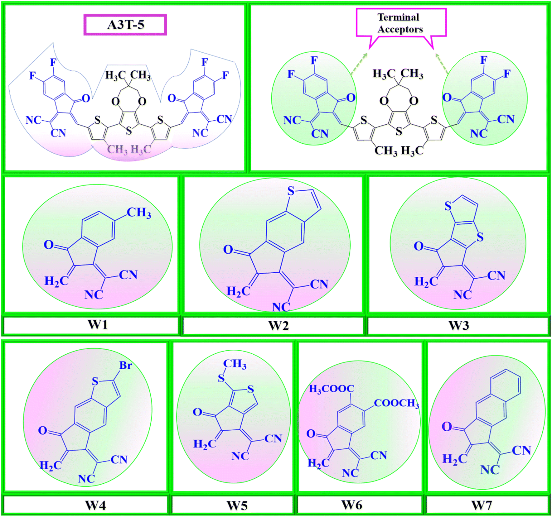 | ||
| Fig. 1 Molecular designing scheme for seven new acceptors based on the core atom of A3T-5, by replacing its terminal structures with seven W1 to W7 terminal structures. | ||
2. Computational methodology
The molecular structures were created by ChemDraw 7.0 software.38 After this step, the processable input files compromising the structure of each molecule were generated with the help of GaussView 6.0 39 software. Gaussian 9.0 40 generated the output files after processing the input files. Gaussian 9.0 implements DFT calculations using several functionals. So, it is important to select the functional that suits best for our work. Hence, the pre-existed A3T-5 molecule was processed, employing various computational functionals, i.e., B3LYP,41 CAM-B3LYP,42 MPW1PW91,43 and wB97XD,44 at 6-31G (d,p) basis set of DFT. Purpose of using different functional is to enhance the accuracy of work as different functionals provide varying values. The accuracy can be improved by selecting one method that delivers the closest results as compared to the experimental results of a particular compound that has already been published.45 The results obtained as an outcome of the computational processing by Gaussian 9.0 software were visualized using GaussView 6.0 software. In the first step of the working procedure, the A3T-5 molecule (specified as reference molecule “R” in this work) was optimized at different density functionals of DFT. After optimization, A3T-5 was further processed for an in-depth study of its spectra and other optoelectronic properties. Each functional has a distinct spectrum in comparison to the others. Chloroform was selected as a solvent using the IEFPCM solvation approach in conjunction with the TD-SCF approach for computations in the solvent phase.46,47 Origin 6.0 software48 was employed to plot the graphs of data obtained by computational processing of reference molecule at different density functionals. Results were contrasted to published experimental values of the A3T-5. Analyses of the absorption spectra of all density functionals in the excited (S1) state revealed a strong correlation between the maximum absorption coefficient (λmax) value of MPW1PW91 functional and the practical λmax value of the A3T-5. Zhu and coworkers revealed through experiments that the A3T-5 molecule shows λmax value at 652 nm in chloroform.35 In our investigation, λmax values obtained by using B3LYP, CAM-B3LYP, MPW1PW91, and wB97XD approaches were 716, 560, 681 and 541 nm, correspondingly, as shown in Fig. 2. It can be deduced that MPW1PW91 density functional provided the value that matched most closely to the experimental λmax of A3T-5 i.e., 652 nm as compared to other density functionals. As a result, it can be more suitable to employ the MPWIPW91 technique to conduct further research on designed compounds to get findings that are relatively similar to experimental results.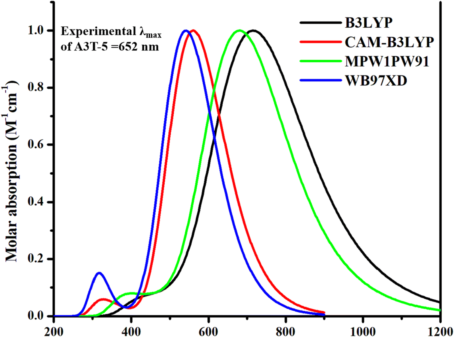 | ||
| Fig. 2 Absorption profile of A3T-5 molecule with four different density functionals of TD-DFT. | ||
The results obtained from the above steps were counter-verified by the density of states (DOS) analysis and transition density matrix (TDM) analysis. Role of different components (acceptor and donor regions) in light absorption was investigated using DOS analysis.48 The data was visualized using the PyMOlyze-1.1 software package.49 The data from the transition density matrix (TDM) data were evaluated using the Multiwfn 3.8 wave function analyzer.50 Internal reorganization energy plays a critical role in the efficient transfer of charges. The electron and hole reorganization energy were evaluated using the equations:51.
| λe = [E0− − E−] + [E0− − E0] | (1) |
| λh = [E0+ − E+] + [E0+ − E0] | (2) |
3. Results and discussion
3.1. Optimized molecular geometries
For the geometrical analysis, molecules were optimized at MPW1PW91/6-31G (d,p) level of theory utilizing Gaussian 9.0 software (shown in Fig. S2†). All the molecules have two portions, i.e., the donor region in the center and the acceptor region at the terminals. The central core consists of “3,3-dimethyl-6,8-bis(3-methylthiophen-2-yl)-3,4-dihydro-2H-thieno[3,4-b][1,4]dioxepine” subunit and is common in all the molecules. On the contrary, all the molecules have different acceptor subunits. Thus, the geometrical characteristics at the places where all the molecules differ must be appropriately considered. Therefore, the degrees of planarity and extent of optimization of molecules were estimated by evaluating the bond lengths and angles between adjoining C–C atoms in donor and terminal acceptor portions. The small bond angle between the donor–acceptor carbon atoms indicates that each molecule is very planar. In a similar manner, the length of the bonds in a molecule indicates the extent of effective optimization of each molecule.53,54 The calculated data for bond lengths and bond angles of A3T-5 and newly fabricated molecules have been summarized in Table 1.| Molecules | Bond length (Lc–c) (Å) | Bond angle (θ°) | Molecular planarity parameter (Å) | Span of deviation (Å) |
|---|---|---|---|---|
| A3T-5 | 1.41 | 0.62 | 0.03 | 0.14 |
| W1 | 1.41 | 0.61 | 0.04 | 0.17 |
| W2 | 1.41 | 0.61 | 0.04 | 0.17 |
| W3 | 1.41 | 0.63 | 0.05 | 0.21 |
| W4 | 1.41 | 0.58 | 0.03 | 0.14 |
| W5 | 1.41 | 0.94 | 0.09 | 0.51 |
| W6 | 1.41 | 0.61 | 0.26 | 2.03 |
| W7 | 1.41 | 0.74 | 0.07 | 0.32 |
In the A3T-5 molecule, the bond angle between adjacent C atoms of donor and acceptor regions is 0.6264° which is quite a small value. It shows that the molecule's acceptor and donor regions are considerably planer. In case of newly developed molecules (W1 to W7) the value of bond angle is 0.6126°, 0.6121°, 0.6359°, 0.5808°, 0.9467°, 0.6129°, 0.7428° respectively. These values show that all the designed molecules also have a minimal bond angle between donor and acceptor regions which clears that all these molecules are highly planer in nature. Among all the molecules, W4 showed the least bond angle value, which makes it more planer and stable as the planarity of molecules is directly linked to the stability of molecules. The reason for such high planarity of all these non-fused OSC molecules is the presence of non-covalent S⋯O interactions between adjacent thiophene subunits, making them more stable.35,55
The bond angle between neighboring C–C atoms of donor and acceptor subunits is the same, i.e., 1.41 Å in the case of all the molecules under study. This value lies in between the typical C–C and C![[double bond, length as m-dash]](https://www.rsc.org/images/entities/char_e001.gif) C bond lengths. It shows that the carbon atoms which are linking donor and acceptor regions with each other are neither completely single-bonded nor double-bonded due to π-conjugation. The existence of π-conjugation is very beneficial as it causes ease of CT from donating to accepting regions due to the delocalization of π-electrons. Electronegative CN groups are present in the acceptor regions, which can shorten the bond length by pulling the electrons more strongly toward themselves. It also makes the bond stronger and increases its stability.56 All these factors play a vital part in enhancing the optoelectronic performance of OSCs. Molecular planarity is a measure of the degree to which the atoms in a molecule are arranged in a plane. The span of deviation from the plane (SDP) is a measure of the amount of deviation from a flat or planar structure in a molecule. A low SDP value indicates that the molecule is more planar, while a high SDP indicates that the molecule is more non-planar. A highly planar molecular structure is generally preferred for the active layer in OSCs, as it allows for better overlap between the orbitals of the donor–acceptor materials, which is necessary for efficient charge transfer. The MPP and SDP can affect the efficiency of molecules differently. If the MPP and SDP are too high, it reduces the overlap between the donor and acceptor molecules, which can decrease efficiency. On the other hand, if the MPP and SDP are too low, it can lead to a significant enhancement in the overlap between the donor and acceptor molecules, which can result in an increase in efficiency.
C bond lengths. It shows that the carbon atoms which are linking donor and acceptor regions with each other are neither completely single-bonded nor double-bonded due to π-conjugation. The existence of π-conjugation is very beneficial as it causes ease of CT from donating to accepting regions due to the delocalization of π-electrons. Electronegative CN groups are present in the acceptor regions, which can shorten the bond length by pulling the electrons more strongly toward themselves. It also makes the bond stronger and increases its stability.56 All these factors play a vital part in enhancing the optoelectronic performance of OSCs. Molecular planarity is a measure of the degree to which the atoms in a molecule are arranged in a plane. The span of deviation from the plane (SDP) is a measure of the amount of deviation from a flat or planar structure in a molecule. A low SDP value indicates that the molecule is more planar, while a high SDP indicates that the molecule is more non-planar. A highly planar molecular structure is generally preferred for the active layer in OSCs, as it allows for better overlap between the orbitals of the donor–acceptor materials, which is necessary for efficient charge transfer. The MPP and SDP can affect the efficiency of molecules differently. If the MPP and SDP are too high, it reduces the overlap between the donor and acceptor molecules, which can decrease efficiency. On the other hand, if the MPP and SDP are too low, it can lead to a significant enhancement in the overlap between the donor and acceptor molecules, which can result in an increase in efficiency.
The calculated values of MPP and SDP for A3T-5 and newly presented molecules are enlisted in Table 1. The MPP values of A3T-5 and newly developed molecules (W1 to W7) are; 0.0381 Å, 0.0448 Å, 0.0427 Å, 0.0531 Å, 0.0367 Å, 0.0992 Å, 0.2664 Å, and 0.0763 Å respectively. It shows that the W4 molecule has the most negligible MPP value, indicating that it has a more planner structure than the rest of the molecules. In the case of SDP, the calculated values of all mentioned molecules are; 0.1477 Å, 0.1722 Å, 0.1717 Å, 0.2165 Å, 0.1450 Å, 0.5112 Å, 2.0336 Å, and 0.3245 Å respectively. Again, W4 has the minimum SDP, which indicates that this molecule has a highly planar configuration. The deviations of the atoms from the plane are shown in Fig. 3. The atoms which deviate above the fitted plane of symmetry are marked by blue color, while the atoms that lie below the plane are indicated by red color. The white color shows the atoms that are totally in a planner sequence. W6 shows maximum values of MPP and SDP due to the presence of four bulky –COOCH3 groups. These groups have oxygen atoms that contain lone pairs of electrons, which cause more steric hindrance and push the oxygen atoms out of the plane to acquire stability.57 Overall. It can be observed that the MPP and SDP values of all the molecules are not much high. This shows that all these molecules have high stability and can show better overlap between the molecular orbitals of the donor and acceptor regions which is vital for enhanced efficiency of OSCs.
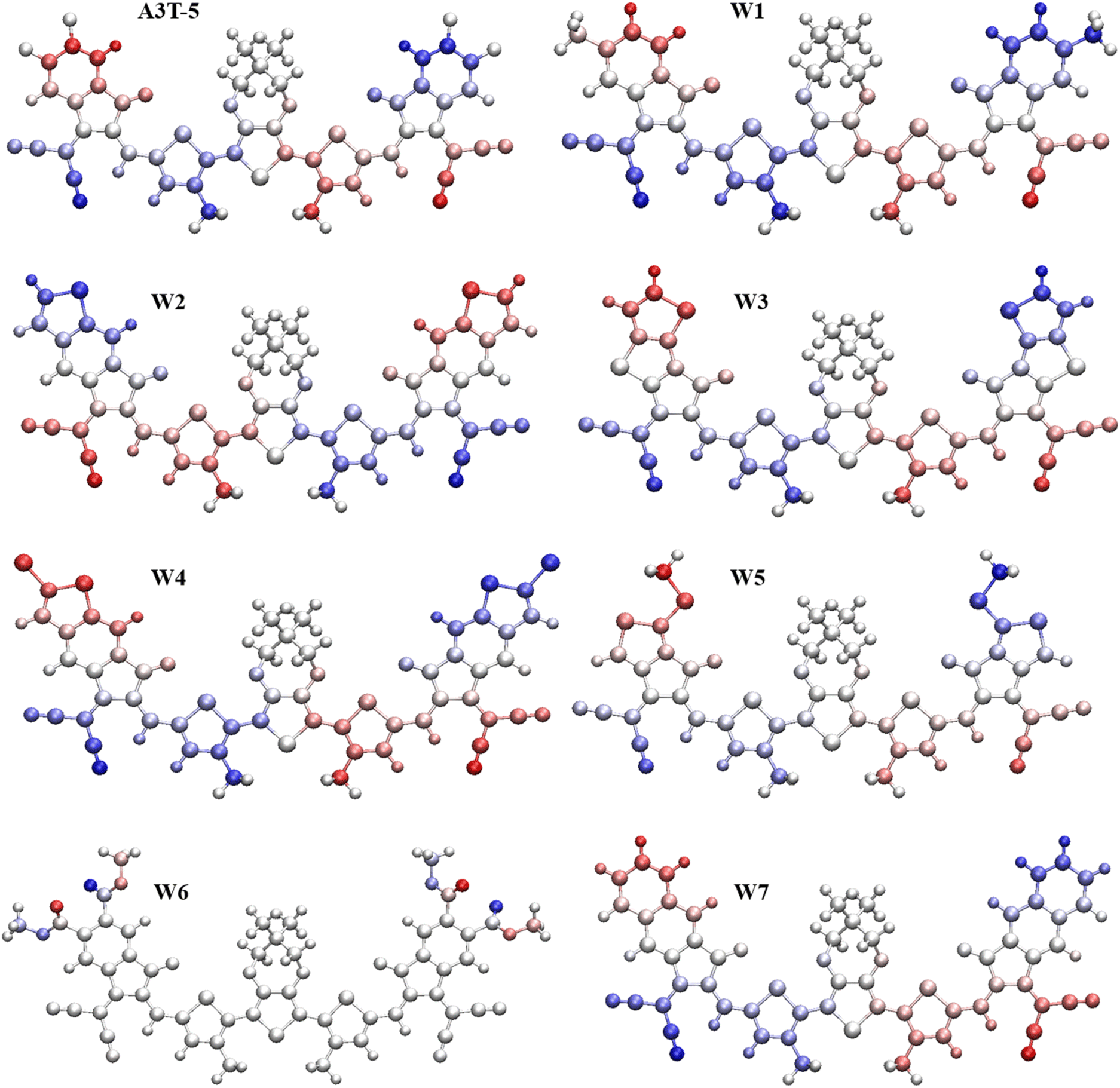 | ||
| Fig. 3 SDP and MPP of optimal geometries of all studied molecules. | ||
3.2. Frontier molecular orbitals (FMOs)
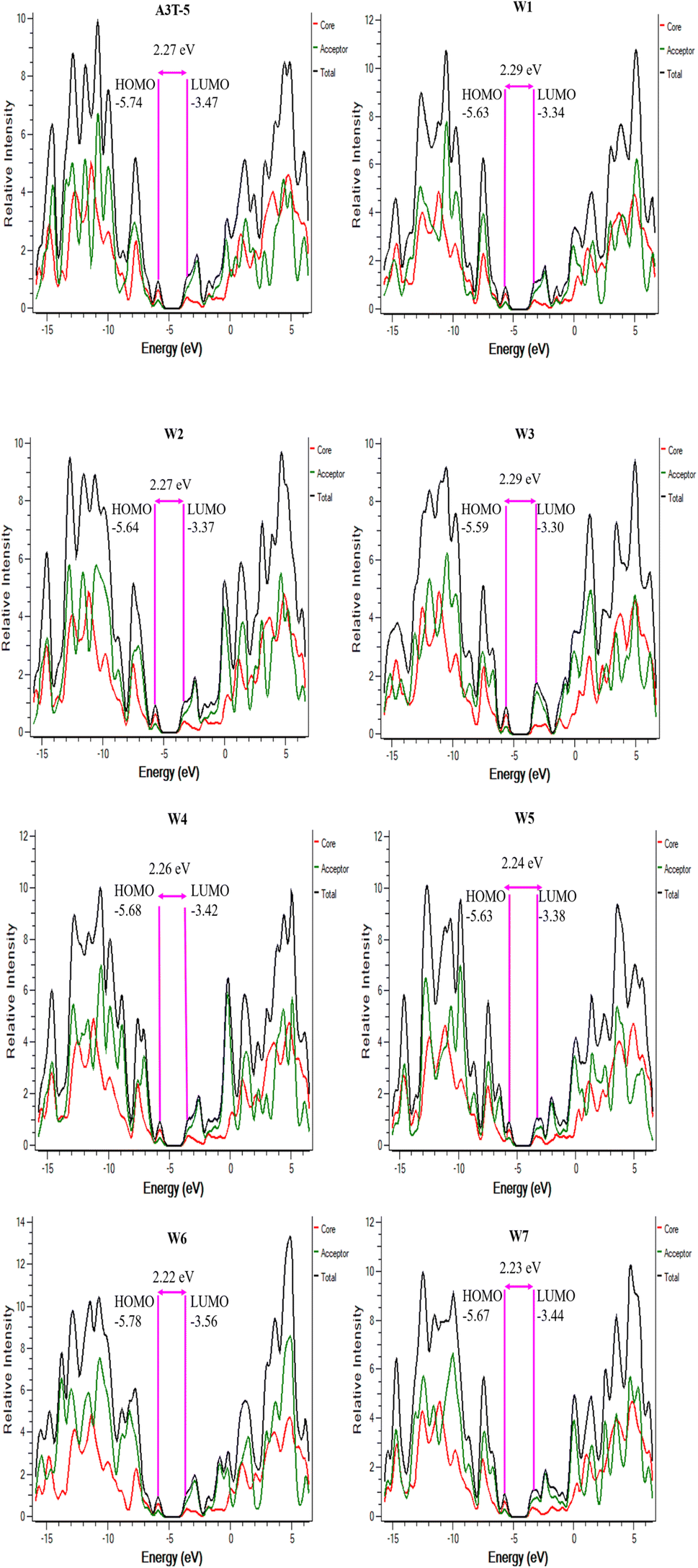
The energy levels of molecular orbitals significantly impact OSCs since these orbitals influence the process of transfer of charges from the donor to the acceptor.58,59 FMOs represent the dispersion of charge density between the ground and excited state energy levels.60 The electron excitation process involves effectively transferring electrons from HOMO to LUMO. This shows that the HOMO energy level is majorly located in the electron-donating region, and the LUMO energy level is located in the electron-accepting region of the molecule (Fig. 4). The HOMO–LUMO energy difference is termed as bandgap that determines the absorption of light by the material and effects the charge mobility and the efficiency of the solar cell.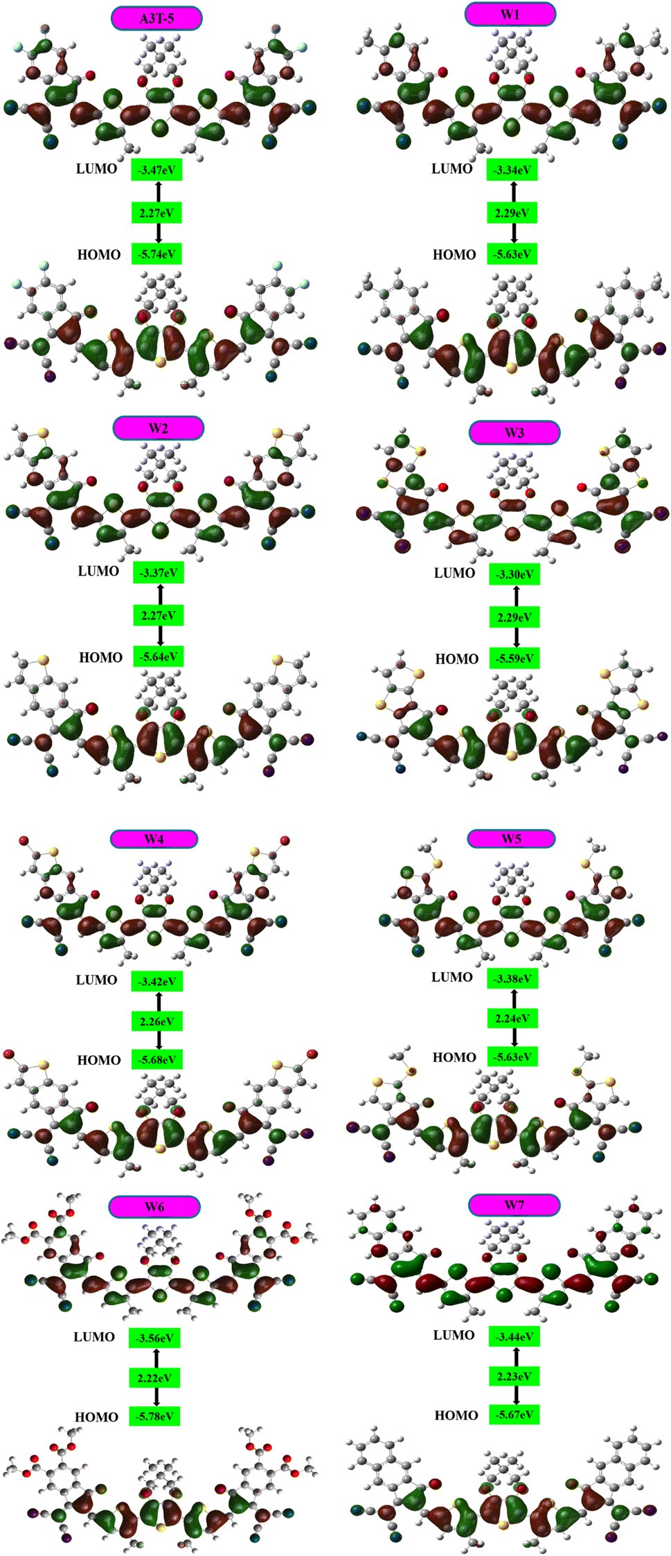 | ||
| Fig. 4 Representation of the band gap and HOMO–LUMO of each molecule. | ||
FMO analysis was done to determine the influence of new acceptors on the charge transfer process. HOMO–LUMO is related to the energy of the electrons that are available to participate in the photovoltaic process. The smaller the band gap, the easier it becomes for electrons to move from the HOMO to the LUMO with very little energy expenditure.61 Fig. 4 portrays the FMOs of reference A3T-5 and devised compounds (W1 to W7) colored according to the strength of charge distribution. The red colors in HOMO–LUMO regions show the areas of high potential (negative potential), while the green color indicates the orbitals with low potential (negative potential). In general, a HOMO lying at a high energy level and LUMO lying at a low energy level are associated with easy excitation and higher solar cell efficiency. This is because higher HOMO and lower LUMO energy levels allow for more significant light absorption, leading to a higher voltage output. The values of HOMO energy levels of A3T-5 and newly presented molecules (W1 to W7) are; −5.74, −5.63, −5.64, −5.59, −5.68, −5.63, −5.78, −5.67 eV respectively. On the other hand, LUMO energy levels of reference and newly proposed molecules lie at; −3.47 eV, −3.34, −3.37, −3.30, −3.42, −3.38, −3.56, −3.44 eV correspondingly (Table 2). It can be observed from the data that almost all our newly designed molecules possess HOMO energy levels at higher energy values than the A3T-5 (reference) molecule due to strong electron-withdrawing acceptors present at peripheral portions. This indicates that designed molecules have the potential to show high efficiency than reference molecule.
| Molecules | EHOMO (eV) | ELUMO (eV) | Eg (eV) | IP (eV) | EA (eV) |
|---|---|---|---|---|---|
| A3T-5 | −5.74 | −3.47 | 2.27 | 6.57 | 2.78 |
| W1 | −5.63 | −3.34 | 2.29 | 6.35 | 2.67 |
| W2 | −5.64 | −3.37 | 2.27 | 6.34 | 2.73 |
| W3 | −5.59 | −3.30 | 2.29 | 6.33 | 2.62 |
| W4 | −5.68 | −3.42 | 2.26 | 6.40 | 2.83 |
| W5 | −5.63 | −3.38 | 2.24 | 6.31 | 2.71 |
| W6 | −5.78 | −3.56 | 2.22 | 6.54 | 2.95 |
| W7 | −5.67 | −3.44 | 2.23 | 6.57 | 2.79 |
A smaller band gap is also linked with higher PCE of OSCs. Smaller bandgap assists the phenomenon of charge transfer (CT).62,63 The HOMO–LUMO bandgap can be calculated by using eqn (3).64
| Eg = ELUMO − EHOMO | (3) |
A high value of HOMO and a low value of LUMO results in a smaller bandgap which is beneficial for achieving highly proficient OSCs. The values of the bandgap for A3T-5 and newly formulated molecules (W1 to W7) are; 2.27, 2.29, 2.27, 2.29, 2.26, 2.24, 2.22, 2.23 eV respectively as expressed in Table 2. The ascending trend of the bandgap of the molecules is; W6 < W7 < W5 < W4 < W2 = A3T-5 < W1 < W3. W6 has a minimum bandgap between its HOMO and LUMO energy orbitals among all the molecules, which shows that CT can efficiently take place in this molecule. It is because of its low-lying LUMO energy levels as compared to other molecules. Furthermore, the existence of strong electron-withdrawing –COOCH3 groups in W6 also facilitates the process of CT in this molecule, along with broadening its absorption spectra and thus boosting its optical parameters. Moreover, W7, W5 and W4 also show low bandgap as compared to the A3T-5 molecule. This can be due to enhanced conjugation in these molecules, which also broadens the absorption spectra and improves the optoelectronic properties of molecules.
Fig. 4 illustrates the energy levels of HOMO residing mainly in the donor regions of all molecules. When it comes to LUMO, the electron density resides on the donor and acceptor parts. Nevertheless, compared to HOMO, the electron density is shifted towards the terminal electron withdrawing acceptors in LUMO of all the investigated molecules. The electronic cloud is shifted towards the peripheral regions due to the existence of strong electron-pulling acceptors. After careful analysis, it can be observed that the spread of electron density towards LUMO of acceptor regions is maximum in W3 and W7 due to increased conjugation in these molecules. Overall, the shift of charge from donor to terminal acceptor regions in all molecules shows that the phenomenon of intramolecular CT is occurring in all these molecules, making them capable of being used as efficient OSCs.
3.3. Adiabatic ionization potential and electron affinity
In OSCs, the ionization potential (IP) of the materials used in the active layer can affect the ability of these materials to transport charges. Materials with high IP tend to have lower charge mobility, as removing an electron and creating a charge carrier in such materials is more complicated. This can lead to reduced performance of the device. On the other hand, materials with low ionization potentials tend to have higher charge mobility, as removing an electron and creating a charge carrier becomes easier.65 These materials can therefore contribute to improved performance of the solar device. Materials with high electron affinity tend to have higher charge mobility, as adding an electron and creating a charge carrier becomes easier. This can lead to improved performance of the device. Thus, solar materials with low electron affinity tend to have lower charge mobility, as it is more difficult to add an electron and create a charge carrier in those materials. These materials can therefore contribute to reduced performance of the solar cell. For intramolecular CT, if the EA of the acceptor portion is high, it will pull the charges more strongly, and charges will move from the donor to the acceptor region.66 This movement of charges enhances the charge transport and, ultimately, the performance of OSCs. For precise evaluations, the adiabatic ionization potential (IP) and electron affinity (EA) were evaluated using eqn (4) and (5).67| IP = [E0+ − E0] | (4) |
| EA = [E0 − E0−] | (5) |
The computed values of IP and EA are summarized in Table 2. The ionization potential of A3T-5 and designed molecules (W1 to W5) is; 6.57, 6.35, 6.34, 6.33, 6.40, 6.31, 6.54, and 6.57 eV sequentially. The value of adiabatic ionization potential varies in increasing order as; W5 < W3 < W2 < W1 < W4 < W6 < W7 = A3T-5. This data demonstrates that almost all the proposed molecules have lower IP as compared to pre-existed A3T-5 molecules. It means that the new molecules have a better ability of charge transport because they can give their electrons with more ease as compared to A3T-5. In the case of electron affinity, the values for A3T-5 and newly developed molecules (W1 to W5) are; 2.78 eV, 2.67 eV, 2.73 eV, 2.62 eV, 2.83 eV, 2.71 eV, 2.95 eV, and 2.79 eV respectively. This indicates that some molecules like W4, W6 and W7 can pull the charges more firmly based on high electron affinity than the A3T-5 molecule. Overall, the values of IP and EA unveil that the new architecture molecules have the ability to perform better as compared to pre-existed A3T-5 molecule. Thus, this new class of molecules may replace less effective OSCs in the future.
3.4. Density of states (DOS) analysis
DOS can be used for determining the total unoccupied positions that are available for electrons at each energy level. It can be used to counter-check the results of FMO analysis. The density of states (DOS) analysis is used to assess the extent of contribution of each portion of a molecule towards the formation of HOMO and LUMO. It shows Mulliken's charge distribution over the surface of each part of the molecule in percentage. For an in-depth analysis, each molecule was subdivided into its two functional units, the central donor/core portion and the terminal acceptors. This makes it possible to precisely check the acceptor and donor regions of the molecule to see whether each part is most likely to function as a HOMO or LUMO contributor.68PyMOlyze 1.1 was used to study Mulliken's charge transfer and to generate the graphs (Fig. 5). The y-axis of the DOS figure represents relative intensity, and the x-axis shows the energy of the orbital. On the x-axis, each graph has three portions. The area on the left with negative energy values represents the HOMO, while the region on the right with positive energy values represents the LUMO. The region of the bandgap is present between these two regions in the center of the x-axis. The contribution of the core/donor part is indicated by the red shade band, while the acceptor is represented by green shade, and the combined role of donor and acceptor portions is marked by the black colored band.69
 | ||
| Fig. 5 DOS graphs of A3T-5 along with newly proposed molecules (W1 to W7). | ||
The role of each portion of all the molecules in developing HOMO–LUMO has been enlisted in Table 3. It can be observed that the donor portion of each molecule is majorly associated with the development of HOMO (indicated by the percentage contribution in Table 3). In comparison, LUMO energy levels are majorly contributed by acceptor regions in all the molecules. We know that charges move from donor to acceptor portions and also from HOMO to LUMO. The higher percentage contribution of LUMO in acceptor regions is advantageous for improved CT from donor to acceptor regions. This factor increases the charge mobility of material, resulting in an increased net efficiency of OSC. W3 is the best of all the molecules being studied in current research. This is because most of its donor part acts as HOMO, while most of its acceptor part acts as LUMO. The HOMO of W3 is contributed by donor and acceptor regions by 71.7% and 28.3%, respectively. In comparison, the LUMO of W3 is raised to 71.5% by the acceptor and 28.5% by the donor region. These attributes facilitate the transfer of charges from the donor to the acceptor region.70 Furthermore, these results coincide with the outcomes of FMO analysis, which shows that all these molecules can be used as improved OSCs.
| Molecules | Excitation energy state | Percentage contribution of donor (eV) | Percentage contribution of acceptor (eV) |
|---|---|---|---|
| A3T-5 | HOMO | 68.7 | 31.3 |
| LUMO | 37.8 | 62.2 | |
| W1 | HOMO | 68.9 | 31.1 |
| LUMO | 37.8 | 62.2 | |
| W2 | HOMO | 67.9 | 32.1 |
| LUMO | 38.3 | 61.7 | |
| W3 | HOMO | 71.7 | 28.3 |
| LUMO | 28.5 | 71.5 | |
| W4 | HOMO | 66.4 | 33.6 |
| LUMO | 37.6 | 62.4 | |
| W5 | HOMO | 67.6 | 32.4 |
| LUMO | 38.0 | 62.0 | |
| W6 | HOMO | 68.1 | 31.9 |
| LUMO | 36.5 | 63.5 | |
| W7 | HOMO | 66.9 | 33.1 |
| LUMO | 36.5 | 63.5 |
3.5. Optical properties
The photovoltaic performance of molecules may be significantly improved or retarded by changing optical and electronic properties. To develop an OSC with remarkable performance, its excitation energy should be low along with greater oscillator strength, and the absorption spectrum should be broader.71 Excitation energy, oscillator strength, charge transfer from HOMO to LUMO, the dipole moment of A3T-5 and all the investigated compounds were determined in the gaseous and solvent phases and are briefed in Tables 4 and 5. All these parameters were computed using the preselected level of theory using the TD-SCF approach. Origin 6.0 was used to gather the molecular absorption spectra of all molecules in the gas and solvent phases (Fig. 6). This makes it possible to discriminate the varying maximum absorption levels more accurately.| Molecules | Calculated λmax (nm) | Excitation energies Ex (eV) | Oscillator strength (f) | Intramolecular charge transfer | Dipole moment (D) |
|---|---|---|---|---|---|
| A3T-5 | 626 | 1.98 | 2.25 | H → L (+99%) | 3.7948 |
| W1 | 622 | 1.99 | 2.29 | H → L (+99%) | 9.0616 |
| W2 | 631 | 1.96 | 2.41 | H → L (+99%) | 8.8836 |
| W3 | 638 | 1.94 | 1.48 | H → L (+99%) | 9.4750 |
| W4 | 636 | 1.97 | 2.49 | H → L (+99%) | 6.6501 |
| W5 | 638 | 1.94 | 2.22 | H → L (+99%) | 10.4638 |
| W6 | 636 | 1.97 | 2.31 | H → L (+99%) | 4.3086 |
| W7 | 644 | 1.92 | 2.43 | H → L (+99%) | 9.8689 |
| Molecules | Exp. λmax (nm) | Calculated λmax (nm) | Excitation energies Ex (eV) | Oscillator strength (f) | Assignment | Dipole moment (D) |
|---|---|---|---|---|---|---|
| A3T-5 | 652 | 681 | 1.82 | 2.48 | H → L (+99%) | 4.2743 |
| W1 | — | 674 | 1.83 | 2.51 | H → L (+99%) | 10.4578 |
| W2 | — | 684 | 1.81 | 2.63 | H → L (+99%) | 10.4847 |
| W3 | — | 686 | 1.80 | 1.72 | H → L (+99%) | 11.4462 |
| W4 | — | 689 | 1.79 | 2.70 | H → L (+99%) | 7.7167 |
| W5 | — | 691 | 1.79 | 2.48 | H → L (+99%) | 12.2511 |
| W6 | — | 695 | 1.78 | 2.50 | H → L (+99%) | 3.8084 |
| W7 | — | 697 | 1.77 | 2.67 | H → L (+99%) | 11.5581 |
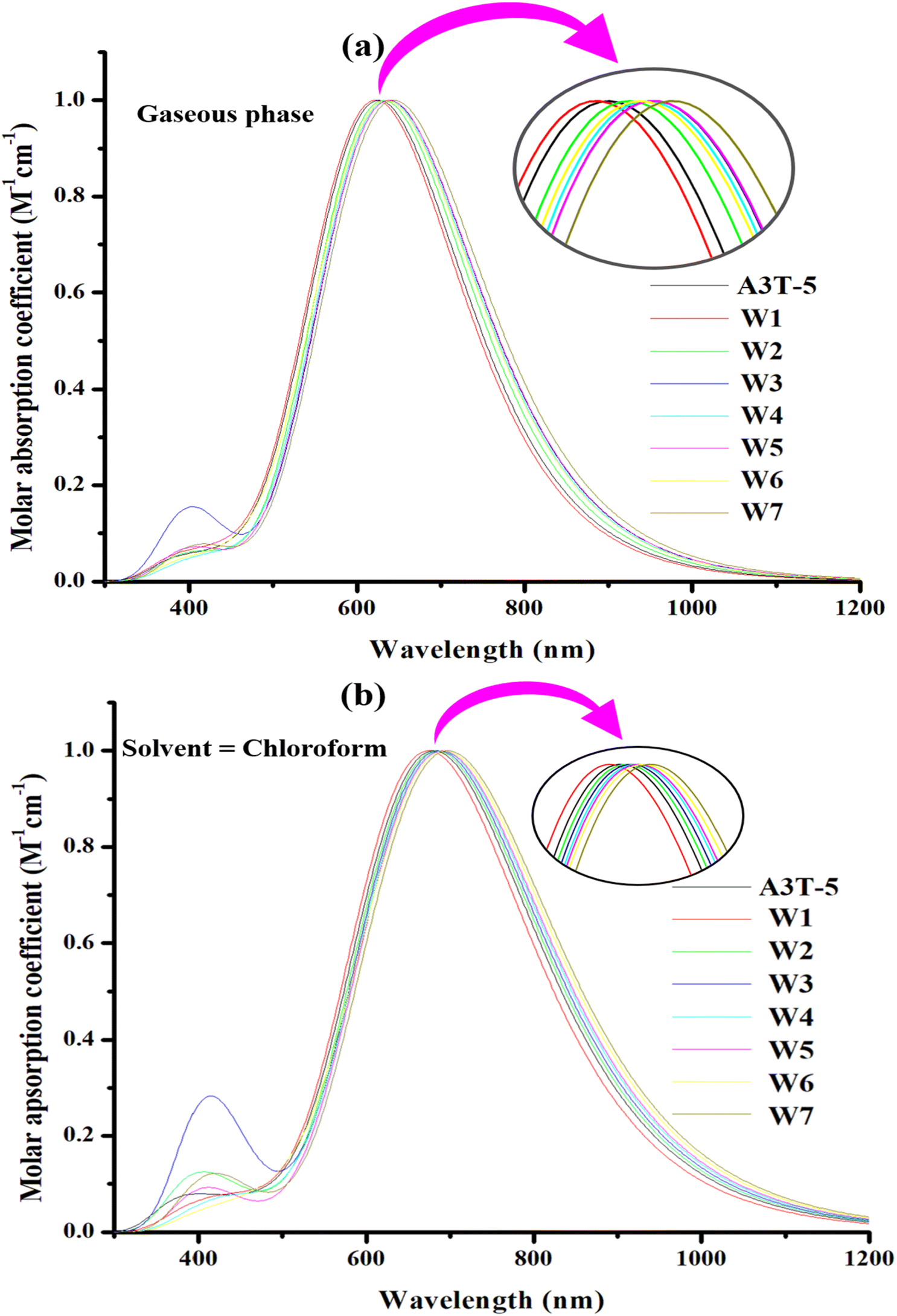 | ||
| Fig. 6 Absorption profile of the molecules in the gas phase (a) and solvent phase (b). The peaks of each molecule are represented in insets that show difference between spectral lines of each molecule more clearly. | ||
In the gaseous phase, the calculated λmax values of reference (A3T-5) and designed molecules (W1 to W7) are 626 nm, 622 nm, 631 nm, 638 nm, 636 nm, 638 nm, 636 nm, 644 nm respectively. It can be clearly noticed that almost all the proposed molecules surpass the pre-existed A3T-5 molecule due to better light absorption by exhibiting redshift. The λmax of molecules in a gaseous medium is increasing in the following trend; W1 < A3T-5 < W2 < W4 = W6 < W3 = W5 < W7. While in solvent (chloroform) medium, almost all the designed chromophores exhibited redshift as compared to the A3T-5 molecule. A3T-5 absorbs light with λmax at 681 nm. At the same time, the λmax of designed molecules (W1 to W7) is 674 nm, 684 nm, 686 nm, 689 nm, 691 nm, 695 nm and 697 nm, respectively. The increasing order of λmax of molecules is; W1 < A3T-5 < W2 < W3 < W4 < W5 < W6 < W7.
Graphs in Fig. 6 illustrate that all the molecules have a remarkable ability to absorb energy in the visible and near-IR region, i.e., from 400 to nearly 850 nm in the gaseous phase and from 400 to nearly 900 nm in chloroform solvent. W7 molecule exhibits maximum λmax in the gaseous phase due to its extensive conjugated network in acceptor regions as compared to all other molecules, as shown in ESI† (ESI-1 & ESI-2). This is because the delocalization of the electrons in the conjugated system results in numerous electronic states that are available for absorption.72 Moreover, as the number of conjugated pi bonds increases, the difference in energy between the HOMO–LUMO reduces, which can increase the λmax of a molecule.
The excitation energy of OSCs is also an important aspect to consider while improving their efficiency. It is described as the minimal level of energy needed to excite an electron from its ground state, or HOMO, to its excited state, or LUMO, and is represented as Ex. When the value of Ex is low, electrons are able to get excited more quickly, allowing for more efficient charge transfer and ultimately enhancing the proficiency of OSC. Moreover, a low Eg value facilitates the charges to reach the first excited state more easily by capturing less amount of energy for excitation. Determining the value of the first excitation energy is vital as it plays a critical role in the excitation process. The first excitation energy of A3T-5 and designed molecules (W1 to W7) in the gaseous phase are 1.98, 1.99, 1.96, 1.94, 1.97, 1.94, 1.97, and 1.92 eV respectively. While in the solvent phase (chloroform), excitation energy values (Ex) are 1.82, 1.83, 1.81, 1.80, 1.79, 1.79, 1.78, and 1.77 eV for A3T-5 and formulated chromophores respectively. It can be observed that the value of Ex is low n chloroform as compared to the gaseous medium for all the molecules. This shows that electrons can get excited by capturing less amount of energy in a solvent medium, making the charge flow easier. W6 and W7 possess the lowest Ex values in both the solvent and gas phases. It means that charges can get excited more quickly in these molecules as compared to all other chromophores, thus enhancing intramolecular CT. This probably can be due to the low bandgap of these molecules. Due to the low bandgap, HOMO–LUMO energy levels get pretty close to each other, making it very easy for the electrons to jump from HOMO to LUMO by absorbing a minimal amount of energy. All proposed chromophores except W1 require less amount of Ex as compared to A3T-5, which makes them a suitable choice as compared to reference A3T-5 to develop efficient OSC devices.
The photovoltaic potential is also affected by the oscillator strength (f) of molecules. In OSCs, the oscillator strength is measured by the frequency of electronic transition between the ground to the excited state (from HOMO to LUMO). A higher charge transfer rate indicates a stronger oscillator strength, as shown by a higher UV-visible absorbance. It is linked directly to the rate of CT, which depends on higher absorption in the UV-visible region. A high value of oscillator strength leads to more electronic transitions caused by the passage of photons. The oscillator strength of A3T-5 and proposed chromophores in the gaseous medium is 2.25, 2.29, 2.41, 1.48, 2.49, 2.22, 2.31, and 2.43, respectively. The oscillator strength for mentioned molecules in a solvent medium is 2.48, 2.51, 2.63, 1.72, 2.70, 2.48, 2.50, and 2.67, respectively. This data shows that the rate of successful transitions is higher in chloroform than in the solvent medium. Except for W3, all other proposed chromophores possess high oscillator strength than the A3T-5 molecule.
Based on all these optical parameters, it can be concluded that all the newly developed molecules have a remarkable ability to be used in the manufacturing of upgraded OSCs because of improved optical parameters. Improving the optical parameters can significantly enhance the efficiency of OSCs, so it will be wise to construct OSC devices based on these new chromophores.
3.6. Dipole moment (μ)
A valuable source to estimate the efficiency of OSCs is the dipole moment. The overall electron density of a molecule is estimated using the dipole moment. It may be used to identify a molecule's polar or non-polar nature. The dipole moment of a molecule may be used to assess the amount of the solubility of that molecule in a particular solvent. The greater the dipole moment, the larger the charge separation and enhances the solubility in polar solvents accompanied by better crystallinity of molecule.73 However, it is inversely linked to the symmetry of molecules. Polar solvents increase the dipole moment of organic compounds, and larger dipole moments result in higher charge mobilities.74 Due to increased charge mobility, it becomes easier for electrons to move from HOMO to LUMO. In this way, the PCE of an OSC molecule is increased.The calculated “μ” of A3T-5 and proposed molecules are summarized in Tables 4 and 5, respectively. The dipole moment of reference (A3T-5) is 3.7948 D in the gaseous medium and 4.2743 D in chloroform. The dipole moment of designed molecules (W1 to W7) in the gaseous medium is; 9.0616 D, 8.8836 D, 9.4750 D, 6.6501 D, 10.4638 D, 4.3086 D, and 9.8689 D. All the newly formulated molecules possess greater dipole moment in the gaseous medium than pre-existed A3T-5. The dipole moment of newly postulated molecules (W1 to W7) in chloroform is; 10.4578 D, 10.4847 D, 11.4462 D, 7.7167 D, 12.2511 D, 3.8084 D, and 11.5581 D respectively. This shows that almost all the proposed molecules have higher dipole moments in chloroform as compared to A3T-5. The value of dipole moment increases in CHCl3 ascribed to the high ionization of electrons in it. W6 shows a decrease in dipole moment in chloroform than the gaseous phase. Four –COOCH3 groups are attached to the acceptor units of the W6 molecule. These groups are of electronegative nature and pull the electrons toward ends. So, chloroform (a solvent having a low dielectric constant) may not have an immense effect on this molecule to increase its polarity further. The increasing trend for “μ” of the described molecules in the gas and solvent medium is; W6 < A3T-5 < W4 < W2 < W1 < W3 < W7 < W5. W5 shows the maximum dipole moment in both mediums, i.e., gas and solvent. It means that there exists maximum charge separation in the W5 molecule.
3.7. Molecular electrostatic potential
MEP analysis provides a three-dimensional representation of molecular charge distribution. The molecular electrostatic potential (MEP) study of selected molecules may be used to determine their charge transfer and reactivity. This approach may be used to identify electrophile and nucleophile attack sites.75 Electrophiles can attack in areas with high charge density, which are shown by yellow and red colors (Fig. 7). Meanwhile, the blue parts of the figure depict the portions of a molecule where the charge density is lower or weaker than the surrounding area. The blue portion marks the possible sites where the nucleophilic attack is most favorable. Green regions show neutral parts of a molecule. MEP analysis can be used to verify the existence of dipole moments. The greater the expanse between the red and blue colors, the higher the molecule's dipole moment, along with a higher charge spread.76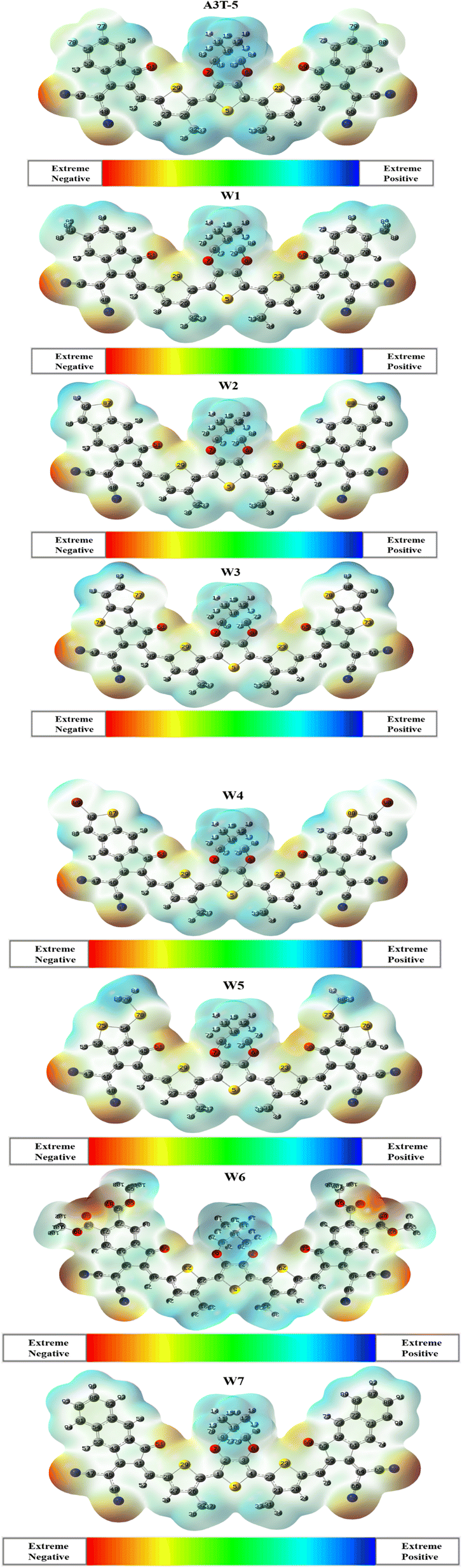 | ||
| Fig. 7 Maps of MEPs of A3T-5 and newly proposed molecules (W1 to W7). | ||
MEP analysis discloses the excellent distribution of the electron density in newly proposed molecules (W1 to W7) from donor to acceptor regions. The blue color is retained by donor terthiophene regions (positive region). At the same time, electronegative atoms in acceptor regions are marked red. This shows that charges moved successfully from the donor to the terminals of acceptor units, and the phenomenon of intramolecular CT occurred in all these molecules. On a closer look, it can be noticed that red color is present in W6 in higher proportion as compared to any other molecule. It is due to the more oxygen (electronegative) atoms in acceptor regions of the W6 molecule. Due to the significant spread of charges, it can be inferred that all the investigated molecules are excellent candidates for effective OSCs since they have different zones depending on the intensity of electron density over the surface of the molecule.
3.8. Light harvesting efficiency (LHE)
LHE is the capability of a material to generate excitons after absorbing energy from photons. It is an important parameter to have an idea about the performance of OSC because it is associated with Jsc (short circuit current). Jsc is directly proportional to the PCE of OSCs.77 A high LHE value results in a large Jsc, which boosts the PCE of the device. The value of the light-harvesting efficiency of molecules can be calculated using the eqn (6):| LHE = 1 − 10−f | (6) |
| Molecules | Oscillator strength | LHE |
|---|---|---|
| A3T-5 | 2.48 | 0.99668 |
| W1 | 2.51 | 0.99690 |
| W2 | 2.63 | 0.99765 |
| W3 | 1.72 | 0.98094 |
| W4 | 2.70 | 0.99800 |
| W5 | 2.48 | 0.99668 |
| W6 | 2.50 | 0.99683 |
| W7 | 2.67 | 0.99786 |
3.9. Exciton binding energy and interaction coefficient
Binding energy refers to the minimal energy needed to generate free electrons and hole carriers during an excitation. Because it is involved in the process of exciton (electron–hole pair) dissociation, the binding energy of molecules has an effect on the efficiency of the photovoltaic device. The efficacy of OCS will be enhanced if excitons' dissociation is made easier and quicker. This outcome is possible when the interaction between electrons and holes is very weak. Under circumstances of strong interaction between exciton and electrons induced by the high binding energy, it becomes difficult to separate electrons and holes. Therefore, lowering the binding energy of OSC systems is critical for higher CT and ultimately enhancing efficiency.66,79 The value of Eb is directly associated with the strength of Coulombic interactions that exist between the hole and the electron. This is calculated by eqn (7).| Eb = Eg − Ex | (7) |
| Molecules | Eb (eV) gaseous | Eb (eV) solvent | Interaction coefficient (gaseous) | Interaction coefficient (solvent) |
|---|---|---|---|---|
| A3T-5 | 0.29 | 0.45 | 0.70291 | 0.70057 |
| W1 | 0.30 | 0.46 | 0.70281 | 0.70037 |
| W2 | 0.31 | 0.46 | 0.70209 | 0.69970 |
| W3 | 0.35 | 0.49 | 0.69465 | 0.69465 |
| W4 | 0.29 | 0.47 | 0.70173 | 0.69953 |
| W5 | 0.30 | 0.45 | 0.70248 | 0.70010 |
| W6 | 0.25 | 0.44 | 0.70246 | 0.70026 |
| W7 | 0.31 | 0.46 | 0.70214 | 0.69972 |
The interaction coefficient is an important parameter to consider as it can significantly impact the optoelectronic properties of the material and the solar cell's performance. It varies inversely with the charge mobility of molecules. Charges may flow more smoothly inside a molecule if their interactions with one another are reduced. The interaction coefficient for A3T-5 and newly proposed chromophores (W1 to W7) in the gaseous phase is; 0.70291, 0.70281, 0.70209, 0.69465, 0.70173, 0.70248, 0.70246, and 0.70214 respectively. Interestingly, all the derived molecules have a low interaction coefficient than the reference (A3T-5), verifying the interaction between the moving charges in all these proposed molecules is less than A3T-5. This results in a higher charge transfer rate in newly proposed molecules. In the solvent phase, the values of the interaction coefficient of A3T-5 and newly proposed chromophores (W1 to W7) are; 0.70057, 0.70037, 0.69970, 0.69187, 0.69953, 0.70010, 0.70026, and 0.69972 respectively. W3 molecule shows the lowest interaction coefficient in the gas and solvent phases. It also clears that all the designed molecules possess a low interaction coefficient in the chloroform (solvent) phase enabling the charges to move more freely across the surface of the molecule. Overall, the findings indicate that all these newly formulated molecules have the potential of greater charge mobility than the reference (A3T-5), which makes them an excellent choice for constructing high-performance, non-fused OSCs in the future.
3.10. Transition density matrix (TDM)
It is one of the most precise approaches for detecting electronic excitation processes. The transition density matrix approach can be employed to understand the process of charge separation and transport within a molecule. TDM can be used to understand how the charge carriers move within a solar cell molecule and how they contribute to the net efficiency of the solar cell.80 While excitation occurs, maps of TDM are adopted to ascertain the interaction between donating and accepting moieties. TDM signifies the migration of charges within a molecule along with the short-lived distribution of electrons and holes during excitation by examining electron-rich simulated orbitals. It can provide insights into the spatial distribution of the charge carriers within solar cell.81 The parts of an OSC molecule with a low concentration of charge carriers may also be identified with the help of the transition density map marked in dark color. These may be points of low productivity in the charge separation and transport process and hence may be optimized to boost solar cell performance.82For TDM analysis, all the investigated molecules are divided into two components, i.e., acceptor (A) and donor (D) regions (Fig. 8). Multiwfn 3.8 software was used to construct a 2-D shadowy figure of the TDM maps at the first excited state, which was computed using the preselected MPWPW91/6-31G(d,p) model of DFT. As hydrogens atoms do not have any impactful contribution to excitation, the technique, by default, ignores their presence. TDM maps show atoms other than hydrogen in the horizontal x-axis and left side of the y-axis. While the right y-axis shows electronic density in a bar shaded with different colors according to strength. As the color changes from blue to red, the electron density on the right vertical axis rises from bottom to top. The distribution of electron density is shown by the bright regions in the graphs.48
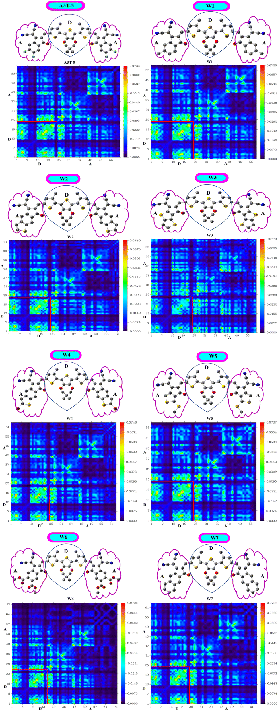 | ||
| Fig. 8 Maps of the transition density matrix of A3T-5 and newly proposed molecules. | ||
All the investigated compounds exhibited a consistent charge distribution and excellent electron delocalization throughout the molecules. A closer look shows that there are more bright fringes in acceptor regions of W3, W5 and W7 molecules. The extent of localization of electron density is marked by fringes in diagonal positions, while fringes in off-diagonal positions reference the process of CT in these molecules. Furthermore, it can be observed that these three molecules have significantly less area of dark spots in acceptor regions which shows that the ratio of excited electrons that moved from the D to A region is very high in the mentioned molecules. Dark portions show the localization of charge density which is also very prominent in D portions of all molecules. A low value of the interaction coefficient (Table 7) of W3 also supports the high CT rate in this molecule. This shows that the adjacently attached thiophene rings in the acceptor unit of W3 are performing better than other electron-withdrawing groups of other molecules in terms of more excitations of charges. TDM analysis shows that these derived molecules are a good option for developing high-performing OSCs.
3.11. Non-covalent interactions (NCI) analysis
Non-covalent interactions in molecules of OSCs can be studied with an understanding of the reduced density graph (RDG) and iso-surface of molecules. RDG represents different types of interactions existing in a molecule in a two-dimensional graph. The non-covalent forces include H-bonding, steric interactions and van der Waals forces.83 RDG was obtained by using Multiwfn 3.8 version software. In the analysis of NCI, λ2 plays a decisive role in deciding the nature of each interaction. Forces of attraction exist between portions of molecules where the value of λ2 is less than zero. On the contrary, when the value of λ2 becomes greater than zero, it indicates the presence of repulsive forces.84Furthermore, red, blue and green colors in NCI graphs show forces of repulsion (steric effect), attractive interactions and van der Waals forces, respectively (Fig. 9). The x-axis of NCI plots shows values of (λ2)ρ (energy) ranging from negative maxima having a value of −0.05 to positive maxima with a value of 0.05 a.u. The y-axis of NCI plots indicates a reduced density gradient. The stability of molecules will be high if there are fewer repulsive and steric interactions. Similarly, strong H-bonding also assists the molecules in acquiring more stability. All the graphs show that attractive forces and van der Waals forces are dominant over steric forces, which confirms the stability of all these molecules. The peaks represent areas where the non-covalent interactions are the strongest. It can be seen in the graphs of all molecules that the blue band (on the left side of the graph) is at a higher position as compared to the red color band (on the right portion of each graph). This shows that attractive forces dominate over repulsive forces in all these molecules, making them stable.
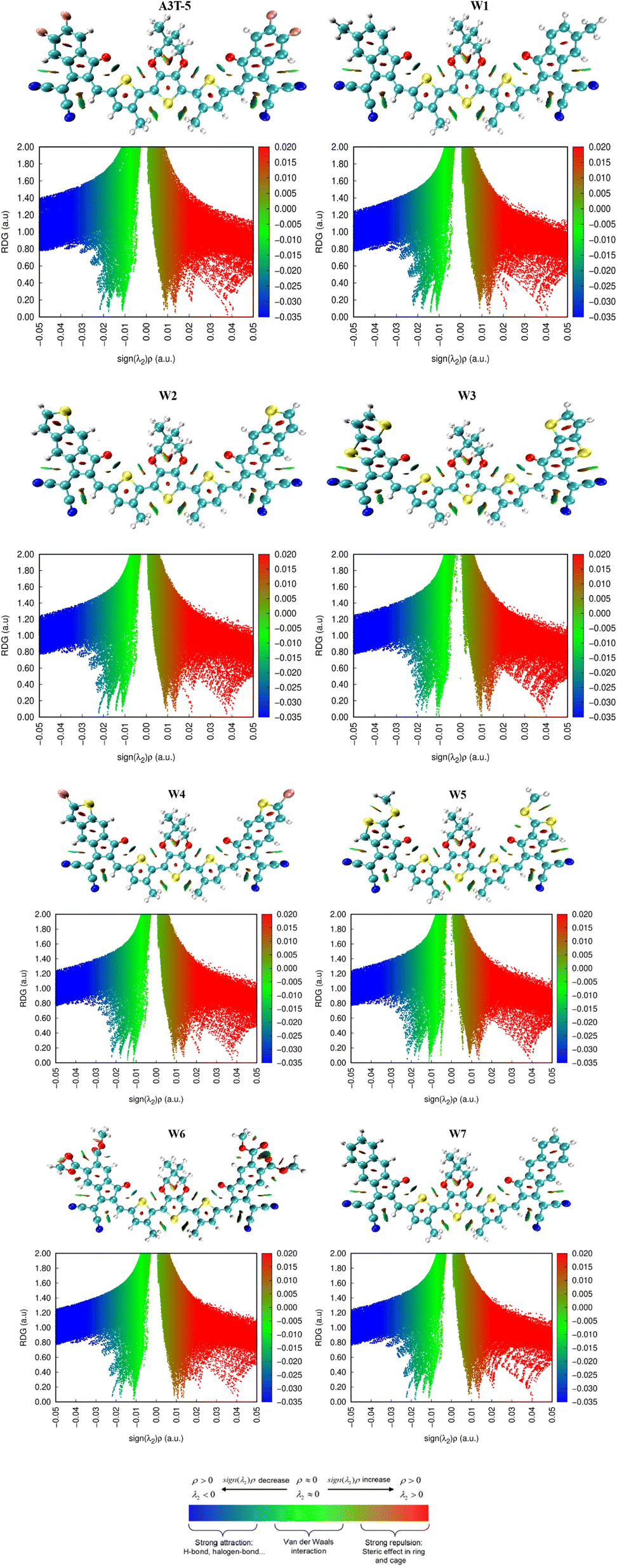 | ||
| Fig. 9 RDG and iso-surface of molecules showing different types of non-covalent interaction. | ||
3.12. Internal reorganization energy
The reorganization energy (RE) of conjugated molecules is a degree of the CT between donor–acceptor portions. Regarding OSCs, RE is used to determine the extent of electron and hole mobility rates.85 According to Marcus' theory, the amount of charge transfer increases when the reorganization energy of the hole–electron decreases. Internal RE (represented by λint) values consider the geometry of cationic and anionic species. Smaller molecules tend to have lower internal reorganization energies, making them more efficient at converting sunlight into electricity.86The internal reorganization energy of organic solar cell molecules has a substantial impact on the device's charge mobility, CT, and efficiency. Higher reorganization energy can lead to slower charge transfer rates, lower charge mobility, and decreased device efficiency. On the other hand, lower reorganization energy can result in faster charge transfer rates, higher charge mobility, and increased device efficiency. The internal reorganization energy of the organic solar cell molecule can also affect the stability of the device. If the reorganization energy is too high, the device may be unstable and prone to degradation. Therefore, optimizing the internal RE of the organic solar cell molecule is necessary to optimize the device's performance.87
The tabulated values of λe and λh (λint of electrons and holes, respectively) are enlisted in Table 8. The values of λe of A3T-5 and designed molecules (W1 to W7) are; 0.008835, 0.009006, 0.008721, 0.006615, 0.008623, 0.008551, 0.008784, and 0.007769 eV respectively. These results show that except W1, all other postulated molecules have a lower value of λe. Furthermore, W3 has a minimum value of λe, which means it has a better rate of flow of electrons and can perform extraordinarily in the process of charge transfer due to its extended conjugation framework consisting of thiophene rings in acceptor regions. Overall, almost all the postulated molecules have a better ability of charge mobility than the W5 molecule, making them an advanced choice to be considered for developing better OSCs.
| Molecules | λe (electron) | λh (hole) |
|---|---|---|
| A3T-5 | 0.008835 | 0.0079942 |
| W1 | 0.009006 | 0.0078477 |
| W2 | 0.008721 | 0.0077570 |
| W3 | 0.006615 | 0.0083617 |
| W4 | 0.008623 | 0.0077499 |
| W5 | 0.008551 | 0.0074407 |
| W6 | 0.008784 | 0.0081987 |
| W7 | 0.007769 | 0.0068675 |
The computed values of λh for A3T-5 and designed molecules (W1 to W7) are; 0.0079942, 0.0078477, 0.0077570, 0.0083617, 0.0077499, 0.0074407, 0.0081987, and 0.0068675 eV respectively. This data unveils that W7 has the maximum capacity for the mobility of its holes created after the dissociations of excitons. However, it can be noticed that the W3 molecule has λe < λh. It shows that the W3 molecule has a better tendency for the mobility of electrons to produce current as compared to holes. Moreover, small values of λe and λh of W5 signify that this molecule can have the highest stability as compared to other molecules. Concisely, it can be interpreted that almost all the newly postulated molecules have better performance in terms of internal reorganization energy. Thus, they have a higher potential for improving charge mobility and boosting performance than the W5 molecule.
3.13. Open circuit voltage (Voc) and fill factor
Voc is a major attribute that impacts an OSC's productivity and performance. The maximum voltages of a solar device are regulated by the difference between energy levels of HOMO (donor), LUMO (acceptor), and rate of charge carrier generation and reassimilation.88,89 In general, a larger energy difference between the LUMO of the acceptor and the HOMO of the donor material results in higher efficiency because it allows the absorption of more energy from photons and facilitates a higher voltage output.90 Voc may be regarded as the optimum amount of the voltages at the time when current across a circuit is minimal or approaches zero value. The bigger the value of Voc, the more improved will be the PCE of an OSC as it directly links to OSCs' efficiency. The Voc of our synthesized molecules is calculated using eqn (8), devised by Scharber.91
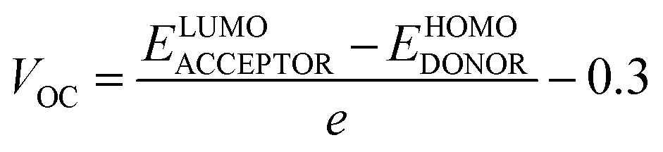 | (8) |
 | ||
| Fig. 10 Comparative representation of the Voc of molecules calculated by employing J61 donor. | ||
The calculated values of Voc of A3T-5 and newly presented molecules are systemized in Table 9, which shows that the Voc of A3T-5 and designed molecules (W1 to W7) is 1.55, 1.68, 1.65, 1.72, 1.60, 1.64, 1.46, and 1.58 eV respectively. Ascending trend for the Voc of studied molecules is; W6 < A3T-5 < W7 < W4 < W5 < W2 < W1 < W3. It reveals that all our newly developed molecules (except W6) show high Voc values than the A3T-5 molecule with great improvement. Surprisingly, W3 shows remarkable Voc with a value of 1.72 eV, which indicates a high degree of improvement in the efficiency of pre-existed A3T-5 molecule. The increased Voc of W3 can be attributed to its planner configuration and strong electron acceptor units, which pull the electronic cloud and increases the delocalization of electrons. Furthermore, a very low interaction coefficient and low reorganization energy of electrons are also the main factors contributing towards increasing the charge mobility and hence enhancing the performance of this molecule. The results of the Voc study prove that these newly presented compounds may be used as upgraded and high-performance OSCs in the future.
| Molecules | Voc (eV) | Normalized Voc | FF |
|---|---|---|---|
| A3T-5 | 1.55 | 59.90 | 0.9162 |
| W1 | 1.68 | 64.92 | 0.9214 |
| W2 | 1.65 | 63.76 | 0.9202 |
| W3 | 1.72 | 66.47 | 0.9228 |
| W4 | 1.60 | 61.83 | 0.9183 |
| W5 | 1.64 | 63.38 | 0.9198 |
| W6 | 1.46 | 56.42 | 0.9121 |
| W7 | 1.58 | 61.06 | 0.9174 |
One more crucial aspect that directly affects OSCs' efficiency is the fill factor of molecules. The fill factor (FF) of an OSC is a measure of the efficiency with which the cell converts sunlight into electricity. The fill factor is an important parameter because it determines how much of the available sunlight is actually converted into electricity.93 In general, a higher fill factor indicates a more efficient solar cell. The FF of OSCs can be improved by using materials with good transport properties, such as high carrier mobility and low recombination rates.94,95 The eqn (9) is used to calculate the fill factor.
 | (9) |
 shows normalized Voc, e denotes charge, which is kept at unity in this work. KB is used to abbreviate the Boltzmann constant, equal to 8.61733034 × 10⁻⁵ electron volts Kelvin−1. The calculated values of FF are enlisted in Table 9, along with values of Voc and normalized Voc. The tabulated values of FF of A3T-5 and designed molecules (W1 to W7) are; 0.9162, 0.9214, 0.9202, 0.9228, 0.9183, 0.9198, 0.9121, and 0.9174 respectively. This criterion also shows that almost all the newly developed molecules have greater FF and hence, enhanced potential to produce power from sunlight energy. W3 has excellent Voc and FF, which make it a highly recommendable molecule to be used as an efficient OSC. The Voc and FF of molecules can be further improved by using other proficient donor molecules like D-16. In concluding remarks, it can be sagaciously interpreted that newly presented molecules may be used as upgraded and high-performance OSCs according to the extent of improvement they exhibited in various attributes.
4. Conclusion
This research work presents seven novel OSC molecules based on a terthiophene ring with an intent to improve the optoelectronic properties and performance (especially Voc) of pre-existed A3T-5 molecule. The results of different factors reveal significant advancement in almost all the developed molecules making the research work impactful for practical purposes. The reported molecules have a suitably small band gap, excitation energy and ionization potential compared to the pre-existed A3T-5 molecule, making them favorable candidates for use in highly efficient solar cell technology. Devised molecules exhibit noticeable redshift in the gaseous and solvent medium compared to the A3T-5 molecule. Low IP and reorganization energy confirm the higher charge mobility in developed molecules. Even though almost all the molecules showed better characteristics than the A3T-5 molecule, W7 possessed magnificent optoelectronic properties by showing the highest value of λmax, i.e.,644 nm and 695 nm in gas and solvent phases, respectively. It also exhibited a significant value of dipole moment (9.86 D in gas and 11.55 D in solvent), least Ex values, i.e., 1.92 eV and 1.77 eV in gas and chloroform, respectively, low reorganization energy (0.007769 eV) and LHE of 0.99786. Other proposed molecules, especially W3, W5 and W4, also gave promising results. On a summarized note, all the new molecules reported in this work outperformed pre-existed A3T-5 molecules by showing significant improvement, but W3, W5 and W7 molecules performed exceptionally extraordinarily by sowing better improvement on overall Voc and FF parameters. Thus, all newly reported molecules can be considered to develop more proficient OSCs based on terthiophene.Conflicts of interest
The Authors declare no conflict of interest.Acknowledgements
The authors extend their appreciation to the Deputyship for Research & Innovation, Ministry of Education in Saudi Arabia for funding this research work through the project number: IFP22UQU4331174DSR072.References
- B. Kan, X. Chen, K. Gao, M. Zhang, F. Lin, X. Peng, F. Liu and A. K. Jen, Nano Energy, 2020, 67, 104209 CrossRef CAS.
- T. Dai, X. Li, P. Lei, A. Tang, Y. Geng, Q. Zeng and E. Zhou, Nano Energy, 2022, 99, 107413 CrossRef CAS.
- C. Lu, M. Paramasivam, K. Park, C. H. Kim and H. K. Kim, ACS Appl. Mater. Interfaces, 2019, 11(15), 14011–14022 CrossRef CAS PubMed.
- P. Cheng, G. Li, X. Zhan and Y. Yang, Nat. Photonics, 2018, 12, 131–142 CrossRef CAS.
- G. Sivakumar, M. Paramasivam, D. Bharath and V. J. Rao, New J. Chem., 2019, 43(13), 5173–5186 RSC.
- C. Xu, K. Jin, Z. Xiao, Z. Zhao, X. Ma, X. Wang, J. Li, W. Xu, S. Zhang and L. Ding, Adv. Funct. Mater., 2021, 31, 2107934 CrossRef CAS.
- M. Paramasivam, R. K. Chitumalla, S. P. Singh, A. Islam, L. Han, V. Jayathirtha Rao and K. Bhanuprakash, J. Phys. Chem. C, 2015, 119(30), 17053–17064 CrossRef CAS.
- C. Lu, M. Paramasivam, K. Park, C. H. Kim and H. K. Kim, ACS Appl. Mater. Interfaces, 2019, 11(15), 14011–14022 CrossRef CAS PubMed.
- Z. Luo, T. Liu, Y. Wang, G. Zhang, R. Sun, Z. Chen, C. Zhong, J. Wu, Y. Chen and M. Zhang, Adv. Energy Mater., 2019, 9, 1900041 CrossRef.
- C. Yan, T. Liu, Y. Chen, R. Ma, H. Tang, G. Li, T. Li, Y. Xiao, T. Yang and X. Lu, Sol. RRL, 2020, 4, 1900377 CrossRef CAS.
- C. Li, J. Zhou, J. Song, J. Xu, H. Zhang, X. Zhang, J. Guo, L. Zhu, D. Wei, G. Han, J. Min, Y. Zhang, Z. Xie, Y. Yi, H. Yan, F. Gao, F. Liu and Y. Sun, Nat. Energy, 2021, 6, 605–613 CrossRef CAS.
- C. He, Z. Chen, T. Wang, Z. Shen, Y. Li, J. Zhou, J. Yu, H. Fang, Y. Li, S. Li, X. Lu, W. Ma, F. Gao, Z. Xie, V. Coropceanu, H. Zhu, J.-L. Bredas, L. Zuo and H. Chen, Nat. Commun., 2022, 13, 2598 CrossRef CAS PubMed.
- M. U. Saeed, J. Iqbal, R. F. Mehmood, M. Riaz, S. J. Akram, H. H. Somaily, A. M. Shawky, M. Raheel, M. I. Khan, E. U. Rashid and R. A. Khera, J. Phys. Chem. Solids, 2022, 170, 110906 CrossRef CAS.
- A. Tang, Y. Lin and E. Zhou, in Organic Solar Cells, 2022, ch8, pp. 313–333, DOI: DOI:10.1002/9783527833658.
- M. Ans, K. Ayub, I. A. Bhatti and J. Iqbal, RSC Adv., 2019, 9, 3605–3617 RSC.
- B. Xiao, A. Tang, J. Yang, A. Mahmood, X. Sun and E. Zhou, ACS Appl. Mater. Interfaces, 2018, 10, 10254–10261 CrossRef CAS PubMed.
- A. Mahmood, A. Tang, X. Wang and E. Zhou, Phys. Chem. Chem. Phys., 2019, 21, 2128–2139 RSC.
- Q. Nie, A. Tang, Q. Guo and E. Zhou, Nano Energy, 2021, 87, 106174 CrossRef CAS.
- P. Jana, M. Paramasivam, S. Khandelwal, A. Dutta and S. Kanvah, New J. Chem., 2020, 44(1), 218–230 RSC.
- L. Ma, S. Zhang, J. Zhu, J. Wang, J. Ren, J. Zhang and J. Hou, Nat. Commun., 2021, 12, 5093 CrossRef CAS PubMed.
- A. Mahmood, A. Irfan and J.-L. Wang, J. Mater. Chem. A, 2022, 10, 4170–4180 RSC.
- B. Xiao, A. Tang, J. Zhang, A. Mahmood, Z. Wei and E. Zhou, Adv. Energy Mater., 2017, 7, 1602269 CrossRef.
- Z. Hu, J. Wang, Z. Wang, W. Gao, Q. An, M. Zhang, X. Ma, J. Wang, J. Miao and C. Yang, Nano Energy, 2019, 55, 424–432 CrossRef CAS.
- A. Wadsworth, Z. Hamid, J. Kosco, N. Gasparini and I. McCulloch, Adv. Mater., 2020, 32, 2001763 CrossRef CAS PubMed.
- Q. An, W. Gao, F. Zhang, J. Wang, M. Zhang, K. Wu, X. Ma, Z. Hu, C. Jiao and C. Yang, J. Mater. Chem. A, 2018, 6, 2468–2475 RSC.
- H. Ji, J. Li, M. Du, J. Yang, A. Tang, G. Li, Q. Guo and E. Zhou, J. Phys. Chem. C, 2021, 125, 10876–10882 CrossRef CAS.
- W. Xu, X. Ma, J. H. Son, S. Y. Jeong, L. Niu, C. Xu, S. Zhang, Z. Zhou, J. Gao and H. Y. Woo, Small, 2022, 18, 2104215 CrossRef CAS PubMed.
- J. Zhou, Z. He, Y. Sun, A. Tang, Q. Guo and E. Zhou, ACS Appl. Mater. Interfaces, 2022, 14(36), 41296–41303 CrossRef CAS PubMed.
- X. Li, F. Pan, C. Sun, M. Zhang, Z. Wang, J. Du, J. Wang, M. Xiao, L. Xue and Z.-G. Zhang, Nat. Commun., 2019, 10, 1–11 CrossRef PubMed.
- R. Wang, J. Xu, L. Fu, C. Zhang, Q. Li, J. Yao, X. Li, C. Sun, Z.-G. Zhang and X. Wang, J. Am. Chem. Soc., 2021, 143, 4359–4366 CrossRef CAS PubMed.
- Y. Zhang, Y. Ji, Y. Zhang, W. Zhang, H. Bai, M. Du, H. Wu, Q. Guo and E. Zhou, Adv. Funct. Mater., 2022, 2205115 CrossRef CAS.
- T. Dai, A. Tang, J. Wang, Z. He, X. Li, Q. Guo, X. Chen, L. Ding and E. Zhou, Macromol. Rapid Commun., 2022, 2100810 CrossRef CAS PubMed.
- L. Ma, S. Zhang, J. Zhu, J. Wang, J. Ren, J. Zhang and J. Hou, Nat. Commun., 2021, 12, 1–12 CrossRef PubMed.
- Z.-X. Liu, Z.-P. Yu, Z. Shen, C. He, T.-K. Lau, Z. Chen, H. Zhu, X. Lu, Z. Xie and H. Chen, Nat. Commun., 2021, 12, 1–10 CrossRef PubMed.
- J. Zhu, C. Yang, L. Ma, T. Zhang, S. Li, S. Zhang, H. Fan and J. Hou, Org. Electron., 2022, 105, 106512 CrossRef CAS.
- M. Waqas, N. M. A. Hadia, M. M. Hessien, J. Iqbal, G. A. M. Mersal, S. Hameed, A. M. Shawky, Z. Aloui, M. A. A. Ibrahim and R. Ahmad Khera, J. Mol. Liq., 2022, 368, 120770 CrossRef CAS.
- M. Waqas, N. M. A. Hadia, M. M. Hessien, S. Javaid Akram, A. M. Shawky, J. Iqbal, M. A. A. Ibrahim and R. Ahmad Khera, Comput. Theor. Chem., 2022, 1217, 113904 CrossRef CAS.
- R. E. Buntrock, J. Chem. Inf. Comput. Sci., 2002, 42, 1505–1506 CrossRef CAS PubMed.
- R. Dennington, T. A. Keith and J. M. Millam, GaussView 6.0.16, Semichem Inc., Shawnee Mission, KS, USA, 2016 Search PubMed.
- A. Mahmood, J. Yang, J. Hu, X. Wang, A. Tang, Y. Geng, Q. Zeng and E. Zhou, J. Phys. Chem. C, 2018, 122, 29122–29128 CrossRef CAS.
- J. P. Finley, Mol. Phys., 2004, 102, 627–639 CrossRef CAS.
- M. T. Beerepoot, D. H. Friese, N. H. List, J. Kongsted and K. Ruud, Phys. Chem. Chem. Phys., 2015, 17, 19306–19314 RSC.
- J.-D. Chai and M. Head-Gordon, Phys. Chem. Chem. Phys., 2008, 10, 6615–6620 RSC.
- C. Adamo and V. Barone, J. Chem. Phys., 1998, 108, 664–675 CrossRef CAS.
- A. Irfan and A. Mahmood, J. Mex. Chem. Soc., 2017, 61, 309–316 CAS.
- M. U. Khan, M. Khalid, M. N. Arshad, M. N. Khan, M. Usman, A. Ali and B. Saifullah, ACS Omega, 2020, 5, 23039–23052 CrossRef CAS PubMed.
- N. Naeem, T. Tahir, M. Ans, A. Rasool, R. A. Shehzad and J. Iqbal, Comput. Theor. Chem., 2021, 1204, 113416 CrossRef CAS.
- R. A. Shehzad, J. Iqbal, M. U. Khan, R. Hussain, H. M. A. Javed, A. ur Rehman, M. U. Alvi and M. Khalid, Comput. Theor. Chem., 2020, 1181, 112833 CrossRef CAS.
- M. I. Khan, J. Iqbal, S. J. Akram, Y. A. El-Badry, M. Yaseen and R. A. Khera, J. Mol. Graphics Modell., 2022, 108162 CrossRef CAS PubMed.
- T. Lu and F. Chen, J. Comput. Chem., 2012, 33, 580–592 CrossRef CAS PubMed.
- M. Abbas, U. Ali, M. Faizan and M. B. A. Siddique, Opt. Quantum Electron., 2021, 53, 1–14 CrossRef.
- U. Yaqoob, A. Ayub, S. Rafiq, M. Khalid and J. Iqbal, J. Mol. Liq., 2021, 341, 117428 CrossRef CAS.
- M. Rani, J. Iqbal, R. F. Mehmood, S. J. Akram, K. Ghaffar, Z. M. El-Bahy and R. A. Khera, Chem. Phys. Lett., 2022, 801, 139750 CrossRef CAS.
- M. U. Saeed, J. Iqbal, R. F. Mehmood, S. J. Akram, Y. A. El-Badry, S. Noor and R. A. Khera, Surf. Interfaces, 2022, 30, 101875 CrossRef CAS.
- Y. Wang, Z. Liu, X. Cui, C. Wang, H. Lu, Y. Liu, Z. Fei, Z. Ma and Z. Bo, J. Mater. Chem. A, 2020, 8, 12495–12501 RSC.
- S. J. Akram, J. Iqbal, R. F. Mehmood, S. Iqbal, Y. A. El-Badry, M. I. Khan, M. Ans and R. A. Khera, Sol. Energy, 2022, 240, 38–56 CrossRef CAS.
- A. Casey, Y. Han, Z. Fei, A. J. White, T. D. Anthopoulos and M. Heeney, J. Mater. Chem. C, 2015, 3, 265–275 RSC.
- M. Khalid, A. Ali, S. Asim, M. N. Tahir, M. U. Khan, L. C. C. Vieira, F. Alexander and M. Usman, J. Phys. Chem. Solids, 2021, 148, 109679 CrossRef CAS.
- M. Adeel, M. Khalid, M. A. Ullah, S. Muhammad, M. U. Khan, M. N. Tahir, I. Khan, M. Asghar and K. S. Mughal, RSC Adv., 2021, 11, 7766–7778 RSC.
- U. Azeem, R. A. Khera, A. Naveed, M. Imran, M. A. Assiri, M. Khalid and J. Iqbal, ACS Omega, 2021, 6, 28923–28935 CrossRef CAS PubMed.
- K. Srivishnu, S. Prasanthkumar and L. Giribabu, Mater. Adv., 2021, 2, 1229–1247 RSC.
- A. Fatima, A. Farhat, R. Saleem, R. A. Khera, S. Iqbal and J. Iqbal, J. Comput. Biophys. Chem., 2021, 20, 71–84 CrossRef CAS.
- B. Kumari, M. Paramasivam, T. Mukherjee, S. Khandelwal, A. Dutta and S. Kanvah, New J. Chem., 2021, 45(10), 4683–4693 RSC.
- J. Griffith and L. Orgel, Q. Rev., Chem. Soc., 1957, 11, 381–393 RSC.
- T. Sutradhar and A. Misra, J. Phys. Chem. A, 2018, 122, 4111–4120 CrossRef CAS PubMed.
- A. Farhat, R. A. Khera, S. Iqbal and J. Iqbal, Opt. Mater., 2020, 107, 110154 CrossRef CAS.
- K. Cervantes-Salguero and J. M. Seminario, J. Mol. Model., 2012, 18, 4043–4052 CrossRef CAS PubMed.
- S. J. Akram, N. M. A. Hadia, J. Iqbal, R. F. Mehmood, S. Iqbal, A. M. Shawky, A. Asif, H. H. Somaily, M. Raheel and R. A. Khera, RSC Adv., 2022, 12, 20792–20806 RSC.
- U. Mubashar, A. Farhat, R. A. Khera, N. Iqbal, R. Saleem and J. Iqbal, J. Mol. Model., 2021, 27, 1–13 CrossRef PubMed.
- T. N. Chmovzh, E. A. Knyazeva, K. A. Lyssenko, V. V. Popov and O. A. Rakitin, Molecules, 2018, 23, 2576 CrossRef PubMed.
- U. Yaqoob, A. R. Ayub, S. Rafiq, M. Khalid, Y. A. El-Badry, Z. M. El-Bahy and J. Iqbal, J. Mol. Liq., 2021, 341, 117428 CrossRef CAS.
- T.-F. Yeh, W.-L. Huang, C.-J. Chung, I.-T. Chiang, L.-C. Chen, H.-Y. Chang, W.-C. Su, C. Cheng, S.-J. Chen and H. Teng, J. Phys. Chem. Lett., 2016, 7, 2087–2092 CrossRef CAS.
- G. Bary, L. Ghani, M. I. Jamil, M. Arslan, W. Ahmed, A. Ahmad, M. Sajid, R. Ahmad and D. Huang, Sci. Rep., 2021, 11, 1–11 CrossRef PubMed.
- M. Ans, K. Ayub, X. Xiao and J. Iqbal, J. Mol. Liq., 2020, 298, 111963 CrossRef CAS.
- H. Yao, Y. Cui, D. Qian, C. S. Ponseca Jr, A. Honarfar, Y. Xu, J. Xin, Z. Chen, L. Hong and B. Gao, J. Am. Chem. Soc., 2019, 141, 7743–7750 CrossRef CAS PubMed.
- D. Zhao, Q. Lu, R. Su, Y. Li and M. Zhao, Appl. Sci., 2019, 9, 2567 CrossRef CAS.
- X. He, L. Yin and Y. Li, J. Mater. Chem. C, 2019, 7, 2487–2521 RSC.
- L. L. Estrella, M. P. Balanay and D. H. Kim, J. Phys. Chem. A, 2016, 120, 5917–5927 CrossRef CAS PubMed.
- J.-P. Correa-Baena, L. Nienhaus, R. C. Kurchin, S. S. Shin, S. Wieghold, N. T. Putri Hartono, M. Layurova, N. D. Klein, J. R. Poindexter and A. Polizzotti, Chem. Mater., 2018, 30, 3734–3742 CrossRef CAS.
- M. Khalid, M. U. Khan, S. Ahmed, Z. Shafiq, M. M. Alam, M. Imran, A. A. C. Braga and M. S. Akram, Sci. Rep., 2021, 11, 1–15 CrossRef PubMed.
- M. U. Khan, M. Khalid, R. Hussain, A. Umar, M. Y. Mehboob, Z. Shafiq, M. Imran and A. Irfan, Energy Fuels, 2021, 35, 12436–12450 CrossRef CAS.
- A. Rasool, S. Zahid, R. A. Shehzad, M. S. Akhter and J. Iqbal, Comput. Theor. Chem., 2021, 1203, 113359 CrossRef CAS.
- Y. Liu, J. Song and Z. Bo, Chem. Commun., 2021, 57, 302–314 RSC.
- S. Zahid, A. Rasool, S. Zahid, M. Ans, J. Iqbal, I. H. El Azab, G. A. M. Mersal and M. M. Ibrahim, Sol. Energy, 2022, 246, 23–35 CrossRef CAS.
- S. Zahid, A. Rasool, R. A. Shehzad, I. A. Bhatti and J. Iqbal, J. Mol. Model., 2021, 27, 1–14 CrossRef PubMed.
- R. Sikandar, A. Farhat, R. A. Khera, S. Jabeen, A. R. Ayub, P. Langer and J. Iqbal, J. Mol. Graphics Modell., 2021, 106, 107918 CrossRef CAS PubMed.
- H. Kang, G. Kim, J. Kim, S. Kwon, H. Kim and K. Lee, Adv. Mater., 2016, 28, 7821–7861 CrossRef CAS PubMed.
- P. Mahalingavelar, Energy Fuels, 2022, 36(4), 2095–2107 CrossRef CAS.
- M. Ans, M. Paramasivam, K. Ayub, R. Ludwig, M. Zahid, X. Xiao and J. Iqbal, J. Mol. Liq., 2020, 305, 112829 CrossRef CAS.
- N. An, Y. Cai, H. Wu, A. Tang, K. Zhang, X. Hao, Z. Ma, Q. Guo, H. S. Ryu, H. Y. Woo, Y. Sun and E. Zhou, Adv. Mater., 2020, 32, 2002122 CrossRef CAS PubMed.
- M. C. Scharber, D. Mühlbacher, M. Koppe, P. Denk, C. Waldauf, A. J. Heeger and C. J. Brabec, Adv. Mater., 2006, 18, 789–794 CrossRef CAS.
- H. Bin, Z.-G. Zhang, L. Gao, S. Chen, L. Zhong, L. Xue, C. Yang and Y. Li, J. Am. Chem. Soc., 2016, 138, 4657–4664 CrossRef CAS PubMed.
- A. Tang, W. Song, B. Xiao, J. Guo, J. Min, Z. Ge, J. Zhang, Z. Wei and E. Zhou, Chem. Mater., 2019, 31, 3941–3947 CrossRef CAS.
- A. Tang, Z. Xiao, L. Ding and E. Zhou, J. Semicond., 2021, 42, 070202 CrossRef.
- X. Wang, A. Tang, J. Yang, M. Du, J. Li, G. Li, Q. Guo and E. Zhou, Sci. China: Chem., 2020, 63, 1666–1674 CrossRef CAS.
Footnote |
| † Electronic supplementary information (ESI) available. See DOI: https://doi.org/10.1039/d3ra00038a |
| This journal is © The Royal Society of Chemistry 2023 |