DOI:
10.1039/D3RA00007A
(Paper)
RSC Adv., 2023,
13, 18058-18069
Theoretical studies of phosphorene as a drug delivery nanocarrier for fluorouracil†
Received
1st January 2023
, Accepted 29th May 2023
First published on 15th June 2023
Abstract
The interactions between phosphorene nanosheets (PNSs) and 5-fluorouracil (FLU) were explored using the density functional theory (DFT) method and molecular dynamics (MD) simulations. DFT calculations were performed utilizing M06-2X functional and the 6-31G(d,p) basis set in both gas and solvent phases. Results showed that the FLU molecule is adsorbed horizontally on the PNS surface with an adsorption energy (Eads) of −18.64 kcal mol−1. The energy gap (Eg) between the highest occupied and lowest unoccupied molecular orbitals (HOMO and LUMO, respectively) of PNS remains constant after the adsorption process. The adsorption behavior of PNS is not affected by carbon and nitrogen doping. The dynamical behavior of PNS–FLU was studied at T = 298, 310, and 326 K reminiscent of room temperature, body temperature, and temperature of the tumor after exposure to 808 nm laser radiation, respectively. The D value decreases significantly after the equilibration of all systems so that the equilibrated value of D is about 1.1 × 10⁻⁶, 4.0 × 10⁻⁸, and 5.0 × 10⁻⁹ cm2 s−1 at T = 298, 310, and 326 K, respectively. About 60 FLU molecules can be adsorbed on both sides of each PNS, indicating its high loading capacity. PMF calculations demonstrated that the release of FLU from PNS is not spontaneous, which is favorable from a sustained drug delivery point of view.
Introduction
In recent years, targeted drug delivery based on nanotechnology has received considerable attention from researchers in different fields including chemistry, physics, medicine, pharmaceutics, and multidisciplinary sciences.1–3 Nanostructures are capable of dealing with the limitations associated with traditional therapeutics including poor solubility in aqueous medium, low half-life, toxicity, abrupt release, bioavailability, and biocompatibility while preserving their essential pharmacophoric features.4 This avoids the exorbitant costs associated with the design and synthesis of new drugs. So far, various types of nanocarriers have been studied in the pharmaceutical industry, the most widely used of which are lipids,5 liposomes,6 polymers,7,8 dendrimers,9–11 micelles,8 carbon nanotubes,12 and two-dimensional (2D) materials.13
Graphene is a 2D material with exceptional physicochemical properties including chemical and mechanical stability,14 good biocompatibility,15 large surface area,16 and exceptional robustness and flexibility17 that made it a promising candidate for numerous biomedical applications such as in vivo and in vitro diagnostics,18 drug delivery,19,20 and biochemical sensing.21 However, despite the many advantages offered by graphene, it acts as a semi-metal with linear band dispersion at the Fermi level hindering its use in biomedical applications.22 Therefore, we must either look for techniques such as doping23,24 and surface functionalization25,26 to improve the electronic properties of graphene, or design and develop new biocompatible and low-toxic 2D materials for targeted drug delivery.
Black phosphorous (BP) is the most stable allotrope of phosphorous, which is synthesized by heating the white phosphorous (about 200 °C) under high pressure (1.2 GPa).27 BP is composed of layers of puckered structure that are held together via dispersion interactions and resemble the structure of graphite.28 Liu et al. introduced the 2D counterpart of bulky BP as a p-type semiconductor and named it phosphorene.29 The structure of phosphorene is stable and flexible and can be mechanically exfoliated as that of graphene and MoS2. However, single-layer phosphorene has a direct band gap (1.0 eV), which is considerably larger than the band gap value of layered BP (0.31–0.36 eV), and makes phosphorene superior to graphene as a 2D nanocarrier for anticancer drug delivery.30
Recently, many researchers have examined phosphorus as a nanocarrier for targeted drug delivery.31 Luo et al. investigated the electronic and optical properties of functionalized MoS2 and phosphorene as isoniazid (INH) and pyrazinamide (PZA) carriers using density functional theory (DFT) calculations.32 The results showed that both drugs favor physisorption on the 2D materials' surface. The band gaps of MoS2 and phosphorene were found to be unaffected by the adsorption of PZA or INH, except for the MoS2:PZA:INH complexes. The calculated ΔG values at different temperatures and pH conditions revealed that the INH and PZA prefer to desorb from 2D materials at high temperatures and in acidic environments. Iqbal et al. utilized the DFT method to assess the efficacy of phosphorene (PNS) as a carrier for nebivolol drug.33 The results demonstrated that the non-covalent interactions are responsible for PNS–drug complex stability, which facilitate the release of nebivolol at targeted cells. The frontier molecular orbitals and charge decomposition analyses alongside the electron–hole theory and photoinduced electron transfer (PET) processes showed that PNS can be exploited as an effective carrier for the delivery of nebivolol to treat cardiovascular diseases.
5-Fluorouracil (FLU) is an effective topical therapeutic, which has an important role in the treatment of head and neck, colon, and breast cancers.34 It possesses a heterocyclic structure that resembles the structure of pyrimidine molecules of DNA and RNA. Thus, FLU molecule can interfere with nucleoside metabolism and is incorporated into RNA and DNA, leading to cytotoxicity and cell death.35 However, its therapeutic efficacy is hampered by severe side effects such as hand-foot syndrome, myelotoxicity, chest pain, cardiotoxicity, low blood counts, and cognitive impairment that limit its clinical applications.36 Therefore, it seems that the use of nanocarriers can be effective in reducing the unwanted side effects of FLU.
To address the opportunities and challenges described above, the main aim of this work was to study the PNS–FLU interactions using DFT calculations and molecular dynamics (MD) simulations. First, we investigated the electronic structure of PNS, FLU, and the most energetically stable PNS–FLU complex using the DFT method. Also, we explored the effect of doping on the PNS function as a nanocarrier for FLU molecules. The dynamical aspects of PNS–FLU interactions at different temperatures (T = 298, 310, and 326 K that are reminiscent of room temperature, body temperature, and temperature of tumor after exposure to 808 nm laser radiation, respectively) were studied employing atomistic MD simulations. We report the results in terms of several tools such as root-mean-square deviation (RMSD), mean square displacement (MSD), and radial pair distribution functions (RDF). The release pattern of FLU from the surface of PNS was explored with the help of potential of mean force (PMF) calculations.
Computational details
DFT calculations
All geometry optimizations, vibrational frequency calculations, and natural bond orbital (NBO) analysis were carried out using M06-2X functional and 6-31G(d,p) basis set implemented in GAMESS software.37 M06-2X is a hybrid meta-exchange correlation functional that is capable to calculate the noncovalent and weak interactions.38,39 Adsorption energy (Eads) was obtained via the following equation:40| | |
Eads = EPNS–FLU − (EPNS + EFLU) − EBSSE
| (1) |
where EPNS–FLU, EPNS, and EFLU are the total energy of the complex, nanosheet, and drug molecule, respectively. Vibrational frequency calculations were performed to ensure that the optimized geometries are true local minima on the potential energy surface.11 Using vibrational frequency calculations, we also calculated the thermochemistry parameters including ΔG and ΔH of reactions. Molecular Electrostatic Potential (MEP) and frontier molecular orbitals (HOMO and LUMO) profiles were plotted using the optimized structures.41 The electronic molecular properties including HOMO–LUMO energy gap (Eg), electronegativity (χ), chemical potential (μ), electron affinity (A, which is defined as −ELUMO), ionization potential (I, which is defined as −EHOMO), and global hardness (η) of studied species were calculated based on the following equations:42,43
To examine the effect of solvation on the electronic structure and adsorption of FLU on the PNS surface, we considered the implicit solvent effect by applying a polarizable continuum model (PCM) and using the dielectric constant of water (ε = 78.36). The solvation energy is defined as follows:
where Δ
Esol,
Eaq, and
Egas indicate the solvation energy and the total energy of the system in the solvent and gas phase, respectively. The amount of charge transfer upon complex formation and stabilization energies in terms of donor–acceptor interactions between bonding–antibonding orbitals were investigated employing NBO analysis.
44
Molecular dynamics (MD) simulations
To inspect the dynamical behavior of the PNS–FLU system, the mechanism of FLU adsorption on the PNS surface, the loading capacity of PNS, and the release pattern of FLU from nanosheet, all-atom MD simulations were performed using GROMACS 2019.3.45 Also, VMD software was used for trajectory visualization.46 The initial coordinates of PNS and FLU were built with the help of GaussView 5.0 software.47 The PNS structure is composed of 480 atoms with a dimension of 43.0 × 38.1 Å and unsaturated terminal phosphorus atoms. Bonded (bond lengths, bond angles, proper and improper dihedrals) and nonbonded (van der Waals and electrostatic forces) parameters required for MD simulations were generated using the Antechamber program.48 Then, the ACPYPE program was employed to convert the Antechamber output files to topology and coordinates files that are compatible with GROMACS software.49 Details on all force field parameters can be found in the Tables S5 and S6 of the ESI.† To validate the partial atomic charges obtained using the RESP method, we compared them with those of regular uracil in CHARMM36m (Table S7†), which are highly optimized and reliable as a reference for biomolecules. To evaluate long-range electrostatic interactions, the particle mesh Ewald (PME) method was used.50 A 12 Å radius cut-off was considered for short-range nonbonded interactions. PNS and FLU molecules were placed in a cubic solvation box filled with the TIP3P water model and a solvation layer of 10 Å was used. Periodic boundary conditions (PBC) were applied in all directions.51 To mimic the physiological conditions more accurately, a salt concentration (Na+Cl−) of 0.145 M was added to the simulation system. Following steepest descents minimization, the simulation system was brought to desired temperature (T = 298, 310, and 326 K that are reminiscent of room temperature, body temperature, and temperature of tumor after exposure to 808 nm laser radiation, respectively) for 500 ps under NVT ensemble. For this purpose, the simulation system was divided into PNS–FLU and water–ion groups and each part was coupled to a separate temperature coupling bath utilizing the V-rescale coupling method. Then, the pressure was maintained isotropically at 1.0 bar during 500 ps of NPT simulations using the Parrinello–Rahman coupling method. Upon completion of two equilibration phases, the position restraints were released and production MD runs were performed for 50 ns.
Results and discussion
DFT calculations
Adsorption of FLU on top of pristine PNS. Fig. 1 shows the optimized structure and molecular electrostatic potential (MEP) plot of PNS. It is generally believed that nanosheets are repeated in a two-dimensional space; however, we selected a 20.6 × 20.3 Å cluster of PNS comprised of 130 P atoms, which gives rise to precise results and reasonable computational time effort at the same time. To reduce edge effects and preserve charge neutrality, the dangling bonds at the edges of the nanosheet were capped by 32 hydrogen atoms. The average value of the P–P bond length is calculated to be 2.22 and 2.27 Å in each layer and between two layers, respectively. These values are in excellent agreement with previously reported experimental data,52 indicating that utilized functional and basis set are capable of reproducing the geometrical and electronic characteristics of PNS.
 |
| | Fig. 1 (a) Optimized structure, (b) MEP plot of PNS, (c) optimized structure, and (d) MEP plot of FLU molecule calculated at M06-2X/6-31G(d,p) level. Yellow color represents the electron-rich or negatively charged areas, while light blue indicates the electron-deficient or positively charged atoms. | |
The MEP plot of a molecule at a certain point, P(x,y,z), is defined as the force exerted on a hypothetical positive charge located at P(x,y,z) by the electrons and nuclei of the molecule. Therefore, the MEP plot is a useful guide in evaluating the reactivity of molecules toward electrophilic or nucleophilic reactions. In the MEP plots the surfaces are defined based on electron density and represented by a RGB color model so that red regions are more negative than −0.010 a.u., yellow shows the regions with electron density between 0 and −0.010 a.u., green regions are between 0.010 and 0.0 a.u., and blue color represents regions more positive than 0.010 a.u. As expected, the MEP plot of PNS reveals that the electron density is evenly distributed over the PNS atoms; thus, we should consider the MEP plot of the FLU molecule as well to recognize the most stable PNS–FLU configuration. As illustrated in Fig. 1(c), the FLU molecule contains 5 functional groups including F, N1, N2, O1, and O2 that can be involved in chemical interactions.
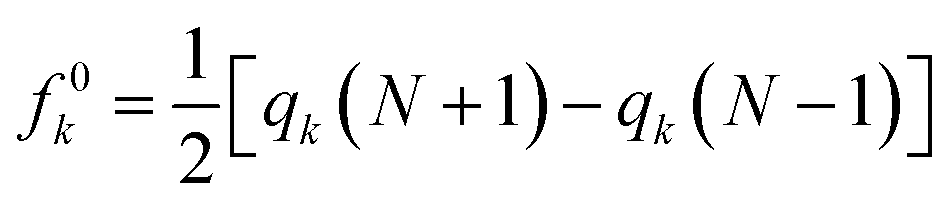
As shown in Fig. 1(d), O1 and O2 are the most negatively charged atoms of FLU molecule, and therefore can act as active sites in nucleophilic attacks. Fukui indices are another set of local reactivity parameters that, along with the MEP can predict the electron density in frontier orbitals (HOMO and LUMO) of a molecule, precisely. Fukui function (fk) is defined as the first derivative of the electronic density (ρ(![[r with combining right harpoon above (vector)]](https://www.rsc.org/images/entities/i_char_0072_20d1.gif) )) of a system concerning the number of electrons (N) at a constant external potential.53,54
)) of a system concerning the number of electrons (N) at a constant external potential.53,54
| |
 | (6) |
Based on finite difference approximation, one can derive Fukui functions in terms of electrophilic (fk−), radical (f0k), and nucleophilic (fk+) attacks.
| | |
fk− = qk(N) − qk(N − 1)
| (7) |
| |
 | (8) |
| | |
fk+ = qk(N + 1) − qk(N)
| (9) |
Using the Fukui function, we found that C1 and O1 are prominent sites for nucleophilic attacks, while O2 prefers to be involved in electrophilic attacks (see Table S1†). The C1, O1, and O2 atoms are also good candidates for radical attacks. To identify the most energetically stable PNS–FLU complex, 6 nonequivalent initial configurations were adopted for adsorption of FLU on top of the PNS cluster in which drug molecule was approached to the nanosheet surface from its (1) F, (2) N1, (3) N2, (4) O1, and (5) O2 head. In the last initial configuration, the FLU molecule was placed on top of the PNS horizontally. The optimized structure of all configurations (PNS–F, PNS–N1, PNS–N2, PNS–O1, PNS–O2, and PNS-h) along with their associated HOMO–LUMO profile and MEP plot are given supplementary material. The initial separation distance between the PNS surface and the FLU molecule was set to ∼1.7 Å in all configurations. After full geometry optimizations, all initial configurations are reoriented to one in which the drug molecule prefers to be adsorbed horizontally on top of the PNS surface. The nearest host–guest interaction distance was found to be about 3.3 Å in all optimized structures. Though the adsorption energies (Eads) are close in value (Table S2†), the least value of Eads belongs to the complex obtained from PNS–O2 starting configuration (−18.64 kcal mol−1) (Fig. 2).
 |
| | Fig. 2 (a) Initial and (b) equilibrated structure of the most stable complex formed between PNS and FLU molecule calculated at M06-2X/6-31G(d,p). | |
The interaction between PNS and FLU molecule in the most stable PNS–FLU complex leads to a charge transfer of 0.038|e| from drug to nanosheet, which is also confirmed by Fukui functions. Inspection of geometrical parameters of the optimized structure indicated that bond lengths and angles remain almost constant upon adsorption of the drug. The most notable changes in bond lengths in the PNS–O2 complex are observed in the case of the C5–O1 bond of the FLU molecule, which increases slightly by about 0.06 Å. To gain a deep understanding of charge transfer occurring between molecular orbitals of interacting species in PNS–FLU complexes, we performed NBO calculations. Table S3† summarizes selected stabilization energies (E(2)) of donor–acceptor interactions in the NBO basis of nanosheet and the drug molecule. The greater the E(2) value, the stronger donor–acceptor interactions. As NBO results indicate, the drug molecule behaves as a stronger donor than the nanosheet and the highest E(2) value belongs to the 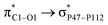 with 5.76 kcal mol−1. These interactions are in line with the geometrical changes upon the adsorption of FLU on top of the PNS molecule. The frontier molecular orbitals (HOMO and LUMO) of a molecule are key factors in the evaluation of its chemical reactivity. Adsorption of FLU molecule on top of PNS could be interpreted as a donor–acceptor interaction between HOMO and LUMO energy levels. Therefore, one can conclude that molecules having a low HOMO–LUMO energy gap are associated with high chemical reactivity and low kinetic stability.55 Shown in Table 1 are the quantum chemistry reactivity parameters for nanosheets and their most stable complexes. It can be seen that PNS has a less negative value of EHOMO compared to FLU, while its ELOMO value is more negative than that of the FLU molecule. Also, the electronegativity of PNS possesses a higher value in comparison with that of the drug. Thus, the charge transfer is expected to occur from FLU to PNS until the chemical potentials of the two species become equal.
Table 1 Calculated adsorption and solvation energies (kcal mol−1). Quantum chemistry reactivity parameters (in eV) including EHOMO, ELUMO, and their associated energy gap (Eg), ionization potential (I), electron affinity (A), electronegativity (χ), electronic chemical potential (μ), chemical hardness (η), and dipole moments (DM in debye) for nanosheets and their most stable complexes
| System |
Phase |
Eads |
EHOMO = −I |
ELUMO = −A |
Eg |
χ |
η |
μ |
DM |
ESolv |
| FLU |
Gas |
— |
−8.2 |
−0.3 |
8.0 |
4.3 |
4.0 |
−4.3 |
3.9 |
— |
| PNS |
— |
−6.8 |
−2.6 |
4.1 |
4.7 |
2.1 |
−4.7 |
0.0 |
— |
| PNS–O2 |
−18.64 |
−6.7 |
−2.6 |
4.2 |
4.7 |
2.1 |
−4.7 |
3.3 |
— |
| CPNS |
— |
−6.6 |
−2.5 |
4.1 |
4.6 |
2.0 |
−4.6 |
0.3 |
— |
| CPNS–N2 |
−18.87 |
−6.6 |
−2.5 |
4.1 |
4.6 |
2.0 |
−4.6 |
3.3 |
— |
| NPNS |
— |
−6.8 |
−2.6 |
4.2 |
4.7 |
2.1 |
−4.7 |
0.5 |
— |
| NPNS–N2 |
−19.03 |
−6.8 |
−2.6 |
4.2 |
4.7 |
2.1 |
−4.7 |
3.4 |
— |
| FLU |
Aqueous |
— |
−8.1 |
−0.1 |
7.9 |
4.1 |
4.0 |
−4.1 |
5.2 |
−9.8 |
| PNS |
— |
−6.8 |
−2.6 |
4.2 |
4.7 |
2.1 |
−4.7 |
0.0 |
−44.6 |
| PNS–O2 |
−15.47 |
−6.8 |
−2.6 |
4.2 |
4.7 |
2.1 |
−4.7 |
5.9 |
−51.3 |
| CPNS |
— |
−6.7 |
−2.5 |
4.1 |
4.6 |
2.1 |
−4.6 |
0.6 |
−44.4 |
| CPNS–N2 |
−15.25 |
−6.6 |
−2.5 |
4.1 |
4.6 |
2.1 |
−4.6 |
6.3 |
−50.5 |
| NPNS |
— |
−6.8 |
−2.6 |
4.2 |
4.7 |
2.1 |
−4.7 |
1.0 |
−44.3 |
| NPNS–N2 |
−15.45 |
−6.8 |
−2.5 |
4.2 |
4.7 |
2.1 |
−4.7 |
6.5 |
−50.5 |
To evaluate the effect of doping on the adsorption behavior of FLU molecule, we replaced a phosphorus atom with a carbon and nitrogen atom and called the doped systems CPNS and NPNS, respectively. The reason for choosing C and N atoms is that they make up a high percentage of the body's cells and are, therefore, biocompatible. In the following, the electronic structure and thermochemical parameters caused by the interaction between the doped PNS and FLU molecule are investigated.
Adsorption of FLU on top of carbon-doped PNS. In the CPNS structure, the C atom is connected to two PL1 and one PL2 atom with a bond length of 1.80 and 1.83 Å, respectively. Here, PL1 represents the P atoms located in the same layer as C and PL2 is the lower layer. The PL1–PL1–PL1 and PL1–PL2–PL1 angles decrease from 97° and 104° in pristine PNS to 105° (PL1–C–PL1) and 123° (PL1–C–PL2) in CPNS, respectively. Based on natural population analysis, the partial atomic charge of C is about −1.15|e|, while the P atoms bonded to it have a partial charge of 0.37 (PL1), and 0.41 (PL2) |e|. To identify the most stable CPNS–FLU and NPNS–FLU complexes, we adopted a procedure same to pristine PNS. After full geometry optimization of all initial configurations, it was revealed that the FLU molecule is adsorbed horizontally on top of doped PNS molecules. In the case of CPNS–FLU complexes, the adsorption energies are in the range of −16.79 to −18.87 kcal mol−1, in which the least and the highest Eads values belong to the CPNS–O1 and CPNS–N2 configurations, respectively. Therefore, we considered the CPNS–N2 conformation as the most stable complex formed between CPNS and FLU molecules, and all further analyses were performed using this structure. Interestingly, the interaction distance between CPNS and the drug molecule increased from 1.78 Å to 3.35 Å, during the optimization process. The most prominent drug → nanosheet stabilization energies (E(2)) are  with 1.65, 0.78, and 0.63 kcal mol−1 values, respectively. While the largest value of E(2) is 0.52 kcal mol−1 when the CPNS acts as a donor group and is related to
  Thus, one can conclude that the FLU molecule acts as a donor group in bonding–antibonding interactions. The bond length changes that take place upon the interaction between CPNS and FLU are in line with the obtained stabilization energies so that the C
![[double bond, length as m-dash]](https://www.rsc.org/images/entities/char_e001.gif) O bonds of the drug are elongated after complex formation. The P–P bond lengths involved in the interaction site show an incremental increase as well. Fig. S7† shows that the HOMO energy level of CPNS is mainly localized over the carbon atom, while the LUMO profile is distributed evenly over the P atoms in the vicinity of doped carbon. Based on Table 1 data and Fig. S8,† the adsorption of FLU on the CPNS does not affect the distribution of HOMO and LUMO energy levels, significantly. So, no noticeable changes are expected to be observed in the CPNS conductivity and its other quantum molecular indicators upon FLU adsorption.
O bonds of the drug are elongated after complex formation. The P–P bond lengths involved in the interaction site show an incremental increase as well. Fig. S7† shows that the HOMO energy level of CPNS is mainly localized over the carbon atom, while the LUMO profile is distributed evenly over the P atoms in the vicinity of doped carbon. Based on Table 1 data and Fig. S8,† the adsorption of FLU on the CPNS does not affect the distribution of HOMO and LUMO energy levels, significantly. So, no noticeable changes are expected to be observed in the CPNS conductivity and its other quantum molecular indicators upon FLU adsorption.
Adsorption of FLU on top of nitrogen-doped PNS. The optimized structure of the most stable NPNS–FLU complex is shown in Fig. S5.† The average P–N bond lengths in the same layer are calculated to be 1.78 Å and the distance between N and the nearest P atom of the lower layer is 1.83 Å, which are considerably less than the P–P bond lengths of pristine PNS. Moreover, the mean value of in-plane and out-of-plane PNP angles are about 103° and 122°, respectively, while the corresponding PPP angles in the PNS structure are 97° and 104°, respectively. Using a strategy same to what is applied in the case of PNS–FLU and CPNS–FLU, we found that all initial NPNS–FLU configurations converge to one in which the drug molecule is located almost parallel to the sheet. The most energetically stable NPNS–FLU complex has an Eads value of −19.03 kcal mol−1 and the nearest host–guest interaction distance is about 3.21 Å (N2FLU⋯NNPNS). Again, NBO analyses clarified that the FLU molecule acts as a strong donor group in complex stabilization. The highest values of E(2) are associated with 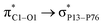 (6.99 kcal mol−1) and
 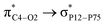 (3.10 kcal mol−1) transfers. NPNS is more electronegative than the FLU molecule, and thus electron density flows from the drug (donor) to the nanosheet (acceptor) with relatively high stabilization energy. The most important back donation from NPNS to FLU is related to the
  with an energy value of 1.11 kcal mol−1. In general, carbonyl groups of the FLU have a key role in donor–acceptor interactions and show a slight bond length increase upon the adsorption process. Total FLU → NPNS charge transfer amount is about 0.04|e|. Same to CPNS, the conductivity and other quantum parameters are not affected by nitrogen doping; thus, doping cannot improve the electrical features of PNS as a drug delivery system for the FLU molecule.
Solvent effect
To mimic the experimental conditions more precisely, geometry optimization and vibrational frequency calculations were repeated for the most stable complexes implying an implicit solvent effect with the help of the PCM model. The values of solvation energy (ESolv) are represented in Table 1. As can be seen from Table 1, the dipole moment of pristine and doped PNS complexes is higher than that of isolated nanosheets, indicating that all complexes are more soluble in water compared to the isolated nanosheets. This finding is supported by the solvation energies (Table 1) obtained for each structure and could be of great relevance from a drug delivery viewpoint. Implying the solvent effect does not have any effect on the dipole moment of pristine PNS, while increasing those of other molecules, considerably. For example, the dipole moment of the FLU molecule increases from 3.9 D in the gas phase to 5.2 D in the aqueous environment. Based on Table 2, the enthalpy changes (ΔH) upon PNS–FLU (−14.0 kcal mol−1) and NPNS–FLU (−14.3 kcal mol−1) complex formation in the solvent phase is less negative than the corresponding values in the gas phase (−17.2 and −18.0 kcal mol−1, respectively). Furthermore, in all cases, the Eads value is less negative in the solvent phase compared to the gas phase. The amount of reduction of Eads in the solvent phase for PNS–FLU, CPNS–FLU, and NPNS–FLU complexes is about 3.17, 3.62, and 3.58 kcal mol−1, respectively. This can be because the PNS and FLU molecules are affected by water molecules, therefore, their interaction becomes weaker in the solvent phase. The more stabilization of isolated molecules in the solvent phase compared to their complexes leads to more positive adsorption energy. The Eads values indicate that the adsorption of FLU on the PNS surface can be categorized as physical adsorption. Donor–acceptor stabilization energies (E(2)) decrease in the solvent phase and confirm the weakening of nanosheet–drug interactions when the implicit solvent effect is taken into consideration (Table S3†).
Table 2 Calculated energetic data (ΔH and ΔG in kcal mol−1), minimum and maximum modes of vibrational frequencies (νmin and νmax in cm−1), recovery time (τ in s), and the nearest interaction distance between PNS and FLU molecules (in Å)
| System |
Phase |
ΔH |
ΔG |
νmin |
νmax |
τ |
r |
| PNS–O2 |
Gas |
−17.2 |
−4.1 |
6 |
3649 |
44.5 |
3.2 |
| CPNS–N2 |
−18.0 |
−5.4 |
4 |
3653 |
65.7 |
3.2 |
| NPNS–N2 |
−18.0 |
−4.7 |
4 |
3651 |
87.1 |
3.2 |
| PNS–O2 |
Aqueous |
−14.0 |
−1.0 |
5 |
3649 |
0.2 |
3.3 |
| CPNS–N2 |
−23.3 |
−2.1 |
4 |
3645 |
0.10 |
3.3 |
| NPNS–N2 |
−14.3 |
−1.5 |
6 |
3641 |
0.21 |
3.2 |
Recovery time
Just as drug adsorption on the surface (or inside) of a nanocarrier is critical to reaching target cells, drug desorption at the right time and place is also essential. Because if the drug strongly interacts with the nanocarrier, it will take a long time for it to be released. On the other hand, if the interactions are very weak, the drug may leave the nanocarrier before it reaches the target cells, which is not desirable from a controlled release point of view. The rate of drug desorption can be evaluated in vitro by heating the nanocarrier under UV light irradiation. The recovery time (τ) is exponentially proportional to Eads and given by the following equation called transition state theory:56where υ shows the attempt frequency (s−1), kB is Boltzmann constant (∼1.99 × 10⁻³ kcal mol−1 K−1), and T represents the recovery temperature (K). Using υ = 10−12 s−1 at room temperature, the required time for desorption of FLU from PNS, CPNS, and NPNS sheets in the solvent phase is calculated to be 0.21, 0.15, and 0.21 s, respectively, showing that PNS and its doped analogs benefit from a short recovery time. The recovery time values obtained in the gas phase are also summarized in Table 2. In general, we found that the doping technique does not improve the PNS features that are important in drug delivery applications. Hence, MD simulations were performed on the pristine PNS–FLU system.
Molecular dynamics (MD) simulations
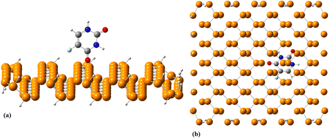
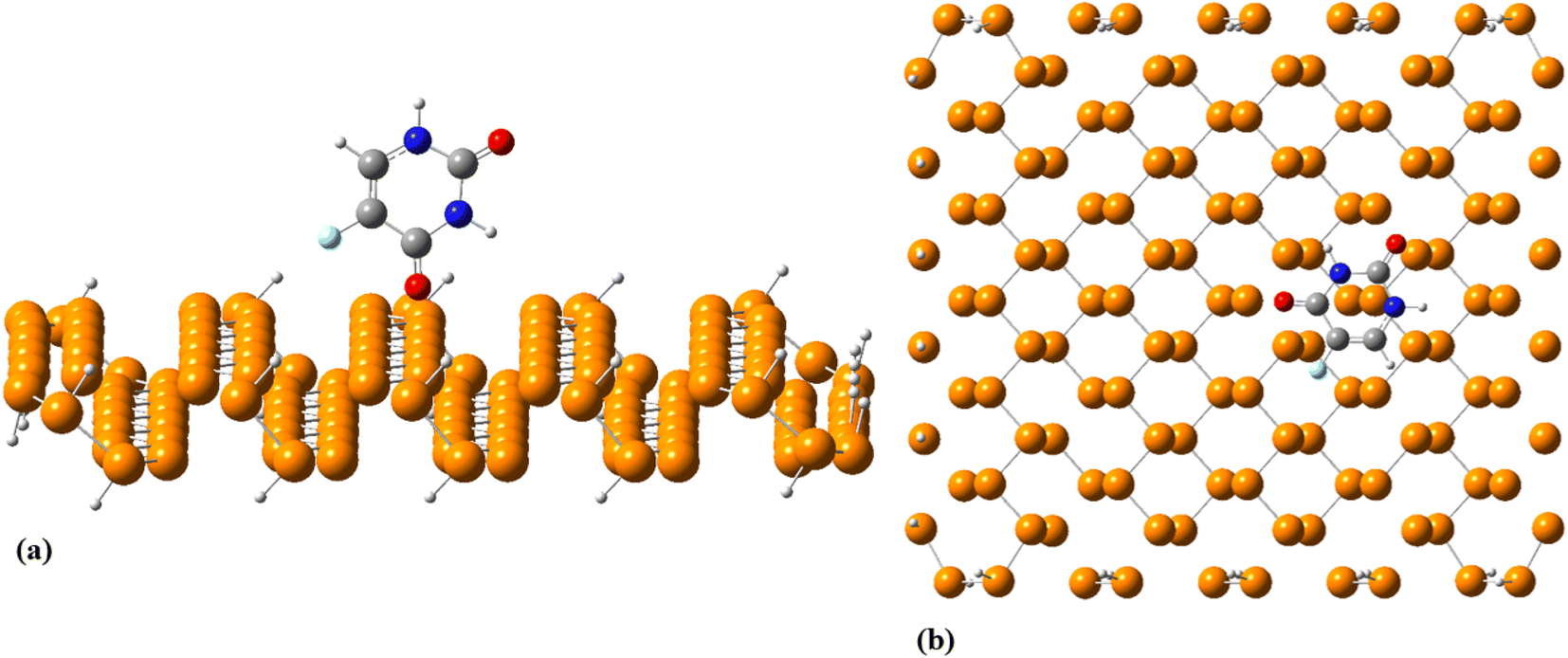
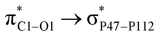
To explore the dynamical behavior of PNS as the FLU nanocarrier, which cannot be evaluated using the DFT method, all-atom MD simulations were performed employing the algorithms and methods previously described in Computational details section. The root-mean-square deviation (RMSD) analysis shows the average distance between the corresponding atoms of a molecule during the simulation time, thus, it can be a measure of stability and structural equilibrium. Fig. S13† shows the RMSD of atomic positions of PNS calculated against its initial configuration, indicating that no substantial changes are observed in the configuration of PNS through MD trajectory. So, the structure of the nanosheet is well equilibrated and the simulation time is long enough to provide information on the nature of interactions between PNS and FLU molecule, loading capacity of PNS, rate of drug release, etc. The equilibrated structure of PNS was then used as starting configuration for PNS–FLU MD simulations. The self-diffusion coefficient (D) of a drug is an essential physicochemical parameter that affects its bioavailability and biodistribution. To evaluate the diffusivity of the FLU and to identify the preferential binding sites between PNS and FLU molecule, we set the drug molecule at a distance of 25 Å from the PNS surface and run production MD without any restraints imposed on the system components. Also, MD simulations were performed at T = 298, 310, and 326 K that reminiscent of room temperature, body temperature, and temperature of the tumor after exposure to 808 nm laser radiation, respectively. Fig. 3(a) shows the center of mass separation distance between the PNS and FLU during the MD run time at different temperatures. The constant PNS–FLU interaction distance indicates that the drug is placed parallel to the surface of PNS, which is in agreement with the DFT results. Side (Fig. 3(b)) and top (Fig. 3(c)) view of PNS–FLU geometry at the end of 50 ns of MD simulations confirm the horizontal adsorption of FLU on the PNS surface.
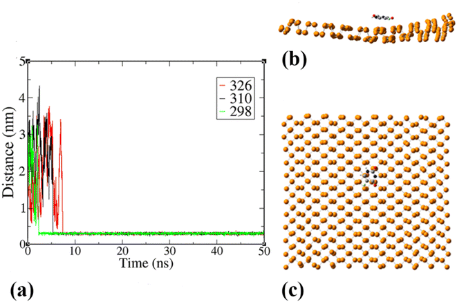 |
| | Fig. 3 (a) Time course of the separation distance between the center of mass (COM) of FLU molecule and PNS surface, (b) side and (c) top view of the equilibrated geometry of PNS–FLU after 50 ns of MD simulations at 310 K. | |
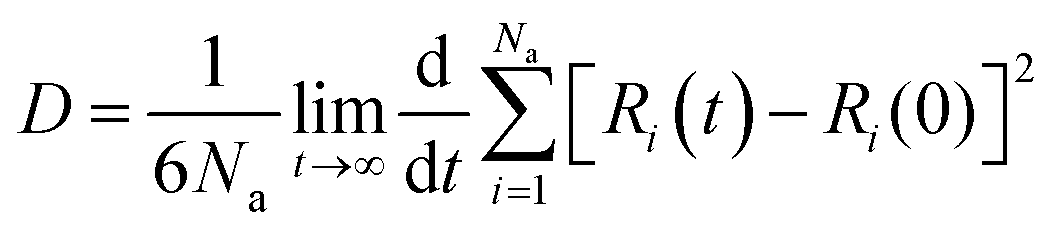
After ensuring the equilibrium of the simulated system, we calculated the migration rate of the drug toward the PNS molecule using the mean square displacement (MSD) analysis tool. The MSD curve and D parameter are given as follows:
| | |
MSD = [Ri(t) − Ri(0)]2
| (11) |
| |
 | (12) |
where
Ri(0) and
Ri(
t) represent the position of FLU at the origin time and a later time,
t, respectively.
Na represents the number of drug molecules.
57 Fig. 4 shows the MSD value of the simulated systems over the 50 ns of MD trajectory. The initial value of the self-diffusion coefficient (
D) is calculated to be about 1.6 × 10
−5, 1.0 × 10
−5, and 0.9 × 10
−5 cm
2 s
−1 at
T = 298, 310, and 326 K, respectively. While, the
D value decreases significantly after the equilibration of all systems so that the equilibrated value of
D is about 1.1 × 10
−6, 4.0 × 10
−8, and 5.0 × 10
−9 cm
2 s
−1 at
T = 298, 310, and 326 K, respectively.
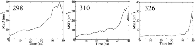 |
| | Fig. 4 The MSD of FLU molecule during 50 ns MD simulations. | |
Lower D values suggest a more potent interaction between the drug and nanosheet. In general, three factors determine the fluctuations in D values: (1) the interaction energy between the nanocarrier and the drug, (2) the surface chemistry of the nanocarrier, and (3) the molecular weight of the drug.58 The diffusion coefficient of the FLU molecule has the lowest value at T = 298 K, indicating the strong interactions and the rapid adsorption of FLU on the PNS surface. The lower D value could be attributed to the slower release of FLU from the nanocarrier; therefore, a longer half-life of the drug is expected.59
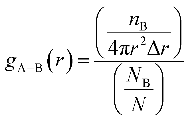
We used radial pair distribution functions (RDF) analysis to more accurately study the orientation of the drug molecule relative to the nanosheet. The RDF plots help us to gain a better insight into the preferential binding sites of adsorbed molecules and host–guest interaction distances. The RDF defines the distribution probability of an atom (B) at a distance (r) around a reference group of atoms (A). The gA–B(r) is given by the following equation:
| |
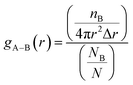 | (13) |
where
nB is the number of B atoms located around the A atoms in a spherical shell with a Δ
r thickness.
NB represents the total number of B atoms in the amorphous cell and
V shows the volume. The RDF plots of the FLU atoms to the PNS molecule at 310 K are shown in Fig. S13.
† As can be seen, the peak of the RDF plots for all atoms appears at the same distance from the nanosheet surface (∼3.2 Å) and confirms that the FLU molecule adopts a parallel orientation relative to the PNS. Time evolution of separation distance between the PNS surface and center of mass (COM) of FLU molecule at
T = 298, 310, and 326 K (
Fig. 3(a)) shows that the host–guest interaction distance remains without changes after about 2.5, 5, and 7 ns, respectively. The mean value of interaction distance is about 3.2 Å for all temperatures and supports the RDF plots.
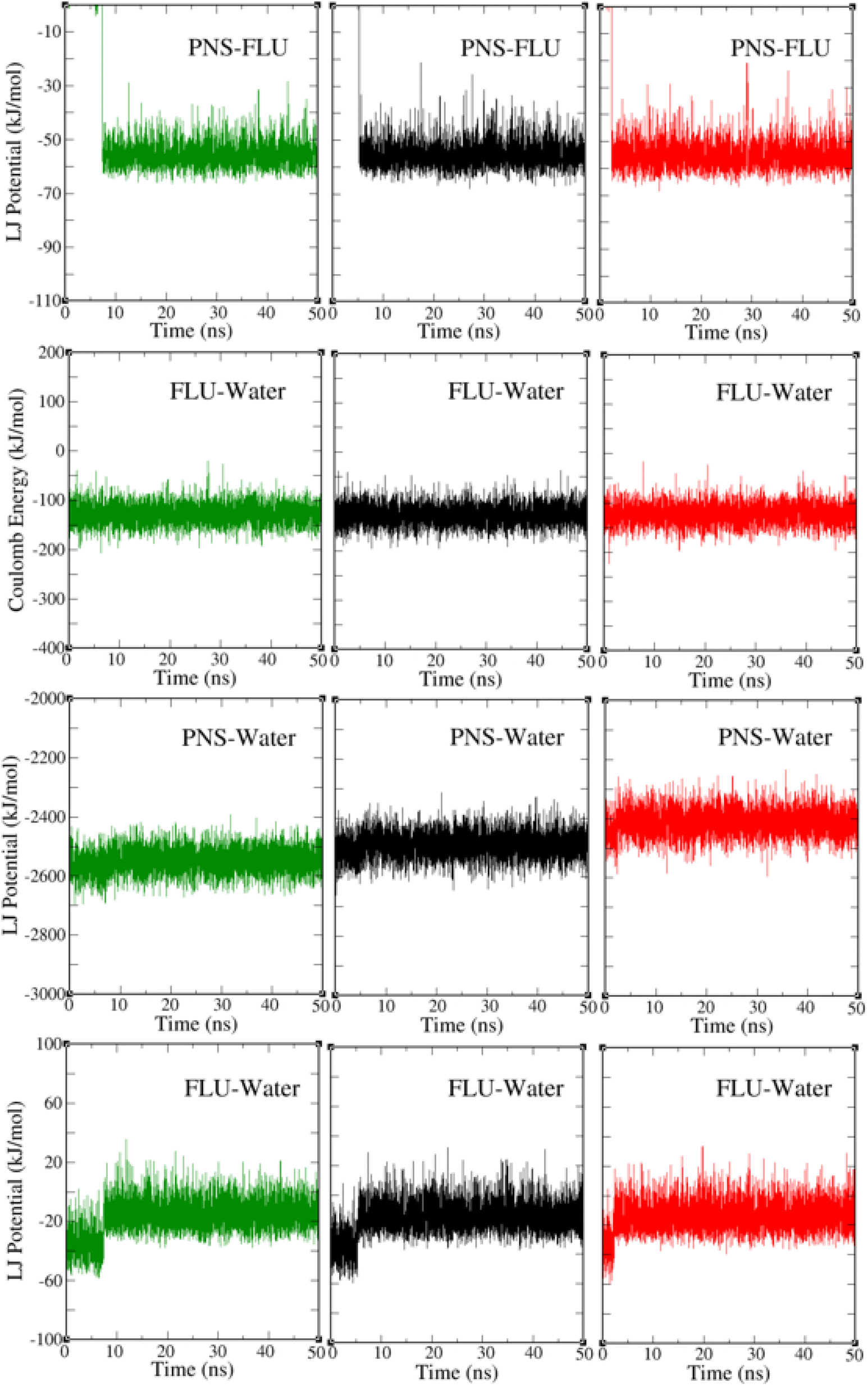
The PNS–FLU, PNS–water, and FLU–water van der Waals interactions and the electric potential energy between the FLU and water molecules at three different temperatures are shown in Fig. 5. After 2.5, 5, and 7 ns from the start of the MD trajectory at 298, 310, and 326 K, respectively, the amount of interaction energies remains constant, indicating that the system has reached an energy equilibrium. This result is in agreement with previously reported RMSD and separation distance plots. The total potential energy of a system is considered as the sum of bonded (bond lengths, bond angles, dihedral and improper angles) and nonbonded (electrostatics and van der Waals) energy terms. From Fig. 5 one can find that van der Waals interactions are the driving forces behind the PNS–FLU stability and coulombic forces have no role in host–guest interactions between PNS and FLU molecules.
 |
| | Fig. 5 The PNS–FLU, PNS–water, and FLU–water van der Waals interactions and the electric potential energy between the FLU and water molecules at 298 K (green plots), 310 K (black plots), and 326 K (red plots). | |
Based on Table 3, increasing of temperature does not affect the intermolecular interactions considerably.
Table 3 Contribution of vdW and electrostatic forces (kcal mol−1) in the intermolecular interactions between simulated system components
| Interaction |
System |
T = 298 K |
T = 310 K |
T = 326 K |
| Einitial |
Efinal |
ΔE |
Einitial |
Efinal |
ΔE |
Einitial |
Efinal |
ΔE |
| LJ |
PNS–FLU |
0.0 ± 0.0 |
−55.9 ± 0.3 |
−55.9 ± 0.3 |
0.0 ± 0.0 |
−56.0 ± 0.2 |
−56.0 ± 0.2 |
0.0 ± 0.0 |
−55.4 ± 0.1 |
−55.4 ± 0.1 |
| PNS–water |
−2569.4 ± 2.1 |
−2548.0 ± 1.6 |
21.4 ± 2.6 |
−2510.6 ± 1.6 |
−2489.4 ± 1.7 |
21.2 ± 2.3 |
−2441.8 ± 1.9 |
−2409.7 ± 1.6 |
32.1 ± 2.4 |
| FLU–water |
−35.3 ± 1.1 |
−14.6 ± 0.3 |
20.7 ± 1.1 |
−34.7 ± 0.5 |
−13.1 ± 0.3 |
21.6 ± 5.5 |
−34.5 ± 1.4 |
−14.1 ± 0.4 |
20.3 ± 1.4 |
| Coulomb |
FLU–water |
−126.6 ± 1 |
−120.4 ± 0.9 |
6.2 ± 1.3 |
−126.0 ± 0.8 |
−120.7 ± 0.7 |
6.3 ± 1.0 |
−125.0 ± 0.3 |
−119.4 ± 0.9 |
6.6 ± 0.9 |
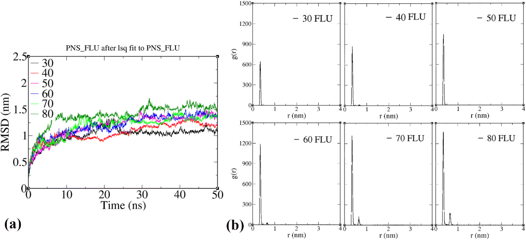
It is well known that only a small amount of chemotherapy drugs can reach the tumor cells. Also, some drug molecules suffer from a short half-life and are prone to be removed by renal clearance or even distributed in healthy tissues. Therefore, the amount of the drug molecules that penetrate the target cells reduces significantly, resulting in frequently repeated administration and thereby high cost and increased side effects. With outstanding advances in nanotechnology-based drug delivery systems, researchers focused on the design of nanocarriers owning high drug loading capacity to reduce dose repetition. Herein, we used a sequential procedure to obtain the loading capacity of the PNS. Six simulation systems consisting of one PNS molecule and 30, 40, 50, 60, 70, and 80 FLU molecules, respectively, were designed and 50 ns of MD simulations were performed for each system. Then, using RDF analysis, we investigated the location of drug molecules on both sides of the nanosheet in each system. After about 25 ns of MD simulations, RMSD plots do not fluctuate considerably, indicating that their overall structure is well equilibrated (Fig. 6(a)).
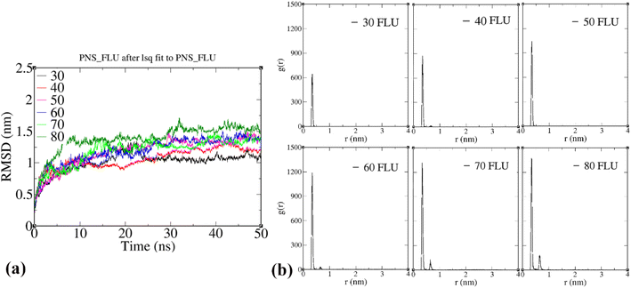 |
| | Fig. 6 (a) Atom-positional RMSD of the PNS–FLU complexes during the MD simulations, (b) radial pair distribution functions (RDF) of the FLU molecules to PNS at 310 K. | |
As illustrated in Fig. 6(b), the RDF plot of systems containing 30–60 FLU molecules shows only a sharp peak at ∼3.2 Å, which means all the drug molecules are very close in terms of interaction distance with PNS and also form a monolayer on the nanosheet surface. The RDF plots also indicate that most of the drug molecules assume a position similar to that observed in the case of the PNS–1FLU system so that the drug molecules are adsorbed horizontally and positioned parallel to the surface of PNS. But when the number of drug molecules exceeds 60 (70 and 80 molecules), in addition to the sharp peak at ∼3.2 Å, a small peak at 7.0 Å also appears. This peak indicates that only 60 molecules of the drug can be adsorbed directly on both sides of the PNS surface, and the rest of the FLU molecules are inevitably adsorbed on the first layer, and therefore their distance from the PNS surface is almost doubled. Thus, it can be said that the loading capacity of PNS is 60 FLU molecules. We considered the system consisting of 60 drug molecules as the optimal system for further MD simulations. Next, we examined the number of hydrogen bonds formed between FLU molecules and water. The average number of hydrogen bonds in PNS–60FLU is 129 at each step and the majority of hydrogen bonds occur between the N and O atoms of FLU and H2O molecules (Fig. S14†).
The potential of mean force (PMF) calculations were carried out using the umbrella sampling method combined with the weighted histogram analysis method (WHAM) to obtain the free energy profile along the reaction coordinate defined as the distance between the PNS surface and FLU center of mass (COM). The FLU molecule was pulled away from the surface of PNS along the z-axis of the simulation box over 500 ps of pulling simulation. A spring constant of 2 kcal mol−1 Å−2 and a pull rate of 0.1 Å ps−1 were used for the umbrella sampling. For PMF calculations, 23 umbrella windows were created at 2 Å intervals over 230 ns of MD simulations. The PMF variation between the PNS surface and COM of the FLU molecule at 310 K is presented in Fig. 6. The free energy barrier was found to be about 4.2 kcal mol−1. Fig. 7 shows that the release of FLU from PNS is not spontaneous, which is favorable from a sustained drug delivery point of view.
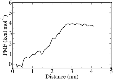 |
| | Fig. 7 Potential of mean force (PMF) plot as a function of PNS surface–FLU center of mass distance at 310 K. | |
Conclusions
In this work, we have investigated the interactions between PNS and FLU molecules using the DFT method and MD simulations. All DFT calculations were performed utilizing M06-2X functional and 6-31G(d,p) basis set. First principle calculations showed that the FLU molecule prefers to be adsorbed on top of PNS horizontally with adsorption energy (Eads) and interaction distance of −18.64 kcal mol−1 and 3.2 Å, respectively. The HOMO–LUMO energy gap (Eg) does not change upon adsorption of FLU molecule, so we doped PNS with carbon and nitrogen atoms (CPNS and NPNS) to evaluate if doping improves the electrical features of PNS as a nanocarrier for FLU molecule. The obtained results showed that the doping technique does not have any effects on the adsorption behavior of FLU on the PNS surface. All DFT calculations were repeated considering the implicit solvent effect and the results were in line with the gas phase. The initial value of the self-diffusion coefficient (D) is calculated to be about 1.6 × 10⁻⁵, 1.0 × 10⁻⁵, and 0.9 × 10⁻⁵ cm2 s−1 at T = 298, 310, and 326 K, respectively. While, the D value decreases significantly after the equilibration of all systems so that the equilibrated value of D is about 1.1 × 10⁻⁶, 4.0 × 10⁻⁸, and 5.0 × 10⁻⁹ cm2 s−1 at T = 298, 310, and 326 K, respectively. About 60 FLU molecules can be adsorbed on both sides of each phosphorene nanosheet, indicating its high loading capacity. Finally, PMF calculations demonstrated that the release of FLU from PNS is not spontaneous, which is favorable from a sustained drug delivery point of view.
Author contributions
All authors have contributed equally.
Conflicts of interest
The authors declare no competing interests.
References
- F. Badalkhani-Khamseh, A. Ebrahim-Habibi and N. L. Hadipour, J. Comput.-Aided Mol. Des., 2017, 31, 1097–1111 CrossRef CAS PubMed.
- J. Cornier, A. Owen, A. Kwade and M. Van de Voorde, Pharmaceutical Nanotechnology, 2 Volumes: Innovation and Production, John Wiley & Sons, 2017 Search PubMed.
- S. Razzaghi, Sci. Rep., 2023, 13 DOI:10.1038/s41598-023-30493-3.
- T. Rasheed, F. Nabeel, A. Raza, M. Bilal and H. Iqbal, Mater. Today Chem., 2019, 13, 147–157 CrossRef CAS.
- M. Nasrollahpour, M. Vafaee and S. Razzaghi, Chem. Eng. Sci., 2022, 260, 117848 CrossRef CAS.
- D. E. Large, R. G. Abdelmessih, E. A. Fink and D. T. Auguste, Adv. Drug Delivery Rev., 2021, 176, 113851 CrossRef CAS PubMed.
- R. R. Wakaskar, Int. J. Drug Dev. Res., 2017, 9, 37–41 CAS.
- M. Ghezzi, S. Pescina, C. Padula, P. Santi, E. Del Favero, L. Cantù and S. Nicoli, J. Controlled Release, 2021, 332, 312–336 CrossRef CAS PubMed.
- F. Badalkhani-Khamseh, A. Ebrahim-Habibi and N. L. Hadipour, J. Mol. Recognit., 2019, 32, e2757 CrossRef PubMed.
- D. Huang and D. Wu, Mater. Sci. Eng., C, 2018, 90, 713–727 CrossRef CAS PubMed.
- F. Badalkhani-Khamseh, A. Bahrami, A. Ebrahim-Habibi and N. L. Hadipour, Chem. Phys. Lett., 2017, 684, 103–112 CrossRef CAS.
- M. Yahyavi, F. Badalkhani-Khamseh and N. L. Hadipour, J. Mol. Liq., 2023, 377, 121393 CrossRef CAS.
- T. Hu, X. Mei, Y. Wang, X. Weng, R. Liang and M. Wei, Sci. Bull., 2019, 64, 1707–1727 CrossRef CAS PubMed.
- J. Liu, L. Cui and D. Losic, Acta Biomater., 2013, 9, 9243–9257 CrossRef CAS PubMed.
- L. Zhang, Z. Lu, Q. Zhao, J. Huang, H. Shen and Z. Zhang, Small, 2011, 7, 460–464 CrossRef CAS PubMed.
- H. Zhang, G. Gruener and Y. Zhao, J. Mater. Chem. B, 2013, 1, 2542–2567 RSC.
- K. S. Kim, Y. Zhao, H. Jang, S. Y. Lee, J. M. Kim, K. S. Kim, J.-H. Ahn, P. Kim, J.-Y. Choi and B. H. Hong, nature, 2009, 457, 706–710 CrossRef CAS PubMed.
- G. Gollavelli and Y.-C. Ling, Biomaterials, 2012, 33, 2532–2545 CrossRef CAS PubMed.
- G. Shim, M.-G. Kim, J. Y. Park and Y.-K. Oh, Adv. Drug Delivery Rev., 2016, 105, 205–227 CrossRef CAS PubMed.
- C. A. Merchant, K. Healy, M. Wanunu, V. Ray, N. Peterman, J. Bartel, M. D. Fischbein, K. Venta, Z. Luo and A. C. Johnson, Nano Lett., 2010, 10, 2915–2921 CrossRef CAS PubMed.
- J. Li, C. Wan, C. Wang, H. Zhang and X. Chen, Chem. Res. Chin. Univ., 2020, 1–9 Search PubMed.
- G. Reina, J. M. González-Domínguez, A. Criado, E. Vázquez, A. Bianco and M. Prato, Chem. Soc. Rev., 2017, 46, 4400–4416 RSC.
- C. Tewari, G. Tatrari, M. Karakoti, S. Pandey, M. Pal, S. Rana, B. SanthiBhushan, A. B. Melkani, A. Srivastava and N. G. Sahoo, Mater. Sci. Eng., C, 2019, 104, 109970 CrossRef CAS PubMed.
- D. Wu, J. Li, S. Xu, Q. Xie, Y. Pan, X. Liu, R. Ma, H. Zheng, M. Gao and W. Wang, J. Am. Chem. Soc., 2020, 142, 19602–19610 CrossRef CAS PubMed.
- S. Liu, T. H. Zeng, M. Hofmann, E. Burcombe, J. Wei, R. Jiang, J. Kong and Y. Chen, ACS Nano, 2011, 5, 6971–6980 CrossRef CAS PubMed.
- O. N. Ruiz, K. S. Fernando, B. Wang, N. A. Brown, P. G. Luo, N. D. McNamara, M. Vangsness, Y.-P. Sun and C. E. Bunker, ACS Nano, 2011, 5, 8100–8107 CrossRef CAS PubMed.
- R. Gusmao, Z. Sofer and M. Pumera, Angew. Chem., Int. Ed., 2017, 56, 8052–8072 CrossRef CAS PubMed.
- P. Lazar, E. Otyepková, M. Pykal, K. Čépe and M. Otyepka, Nanoscale, 2018, 10, 8979–8988 RSC.
- H. Liu, A. T. Neal, Z. Zhu, Z. Luo, X. Xu, D. Tománek and P. D. Ye, ACS Nano, 2014, 8, 4033–4041 CrossRef CAS PubMed.
- G. Wang, W. J. Slough, R. Pandey and S. P. Karna, 2D Mater., 2016, 3, 025011 CrossRef.
- R. Esfandiarpour, F. Badalkhani-Khamseh and N. L. Hadipour, Colloids Surf., B, 2022, 112513 CrossRef CAS PubMed.
- W. Liang and X. Luo, J. Phys. Chem. C, 2020, 124, 8279–8287 CrossRef CAS.
- S. Riaz, K. Jaffar, M. Perveen, A. Riaz, S. Nazir and J. Iqbal, J. Mol. Model., 2021, 27, 1–15 CrossRef PubMed.
- A. Khajeh and H. Modarress, Biophys. Chem., 2014, 187, 43–50 CrossRef PubMed.
- K. Zare, F. Najafi and H. Sadegh, J. Nanostruct. Chem., 2013, 3, 1–8 Search PubMed.
- P. M. Wigmore, S. Mustafa, M. El-Beltagy, L. Lyons, J. Umka and G. Bennett, in Chemo Fog, Springer, 2010, pp. 157–164 Search PubMed.
- M. W. Schmidt, K. K. Baldridge, J. A. Boatz, S. T. Elbert, M. S. Gordon, J. H. Jensen, S. Koseki, N. Matsunaga, K. A. Nguyen and S. Su, J. Comput. Chem., 1993, 14, 1347–1363 CrossRef CAS.
- D. Jeevitha, K. Sadasivam and R. Praveena, DFT investigation of pachypodol for exploring anti-oxidant action–Performance of B3LYP and M06-2X, 2020, pp. 952–961 Search PubMed.
- Y. Zhao and D. G. Truhlar, Theor. Chem. Acc., 2008, 120, 215–241 Search PubMed.
- R. Esfandiarpour, M. R. Hosseini, N. L. Hadipour and A. Bahrami, J. Mol. Model., 2019, 25, 163 CrossRef PubMed.
- F. Pazoki, R. Esfandiarpour, F. Mohsenzadeh, F. Mohammadpanah and A. Heydari, J. Mol. Struct., 2021, 1238, 130389 CrossRef CAS.
- N. M. O'boyle, A. L. Tenderholt and K. M. Langner, J. Comput. Chem., 2008, 29, 839–845 CrossRef PubMed.
- M. R. Hosseini, R. Esfandiarpour, S. Taghipour and F. Badalkhani-Khamseh, Chem. Phys. Lett., 2020, 754, 137712 CrossRef CAS.
- A. E. Reed, L. A. Curtiss and F. Weinhold, Chem. Rev., 1988, 88, 899–926 CrossRef CAS.
- M. J. Abraham, T. Murtola, R. Schulz, S. Páll, J. C. Smith, B. Hess and E. Lindahl, SoftwareX, 2015, 1, 19–25 CrossRef.
- W. Humphrey, A. Dalke and K. Schulten, J. Mol. Graphics, 1996, 14, 33–38 CrossRef CAS PubMed.
- M. Frisch, F. Clemente, M. J. Frisch, G. W. Trucks, H. B. Schlegel, G. E. Scuseria, M. A. Robb, J. R. Cheeseman, G. Scalmani, V. Barone, B. Mennucci, G. A. Petersson, H. Nakatsuji, M. Caricato, X. Li, H. P. Hratchian, A. F. Izmaylov, J. Bloino and G. Zhe, Gaussian 09, revision a. 01, 2009, pp. 20–44 Search PubMed.
- J. Wang, W. Wang, P. A. Kollman and D. A. Case, J. Mol. Graphics Modell., 2006, 25, 247–260 CrossRef CAS PubMed.
- A. W. S. Da Silva and W. F. Vranken, BMC Res. Notes, 2012, 5, 1–8 CrossRef PubMed.
- T. Darden, D. York and L. Pedersen, J. Chem. Phys., 1993, 98, 10089–10092 CrossRef CAS.
- W. L. Jorgensen, J. Chandrasekhar, J. D. Madura, R. W. Impey and M. L. Klein, J. Chem. Phys., 1983, 79, 926–935 CrossRef CAS.
- L. Kou, C. Chen and S. C. Smith, J. Phys. Chem. Lett., 2015, 6, 2794–2805 CrossRef CAS PubMed.
- C. Verma, L. O. Olasunkanmi, E. E. Ebenso, M. A. Quraishi and I. B. Obot, J. Phys. Chem. C, 2016, 120, 11598–11611 CrossRef CAS.
- E. Florez, W. Tiznado, F. Mondragón and P. Fuentealba, J. Phys. Chem. A, 2005, 109, 7815–7821 CrossRef CAS PubMed.
- H. Günther, E. Zolotoyabko, K. Hermann, N. Berova, R. Woody, P. Polavarapu and K. Nakanishi, Molecular Orbitals and Organic Chemical Reactions-Reference Edition, 2022 Search PubMed.
- I. G. Pitt, R. G. Gilbert and K. R. Ryan, J. Phys. Chem., 1994, 98, 13001–13010 CrossRef CAS.
- J. Wang and T. Hou, J. Comput. Chem., 2011, 32, 3505–3519 CrossRef CAS PubMed.
- K. R. Karnati and Y. Wang, Phys. Chem. Chem. Phys., 2018, 20, 9389–9400 RSC.
- A. Solhjoo, Z. Sobhani, A. Sufali, Z. Rezaei, S. Khabnadideh and A. Sakhteman, Colloids Surf., B, 2021, 205, 111823 CrossRef CAS PubMed.
|
| This journal is © The Royal Society of Chemistry 2023 |
Click here to see how this site uses Cookies. View our privacy policy here. 
 Open Access Article
 This Open Access Article is licensed under a Creative Commons Attribution-Non Commercial 3.0 Unported Licence
 *,
Farideh Badalkhani-Khamseh* and
Nasser L. Hadipour
*,
Farideh Badalkhani-Khamseh* and
Nasser L. Hadipour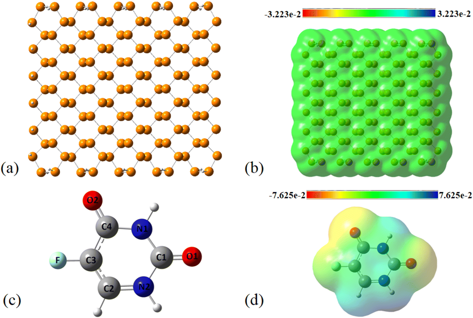
 with 5.76 kcal mol−1. These interactions are in line with the geometrical changes upon the adsorption of FLU on top of the PNS molecule. The frontier molecular orbitals (HOMO and LUMO) of a molecule are key factors in the evaluation of its chemical reactivity. Adsorption of FLU molecule on top of PNS could be interpreted as a donor–acceptor interaction between HOMO and LUMO energy levels. Therefore, one can conclude that molecules having a low HOMO–LUMO energy gap are associated with high chemical reactivity and low kinetic stability.55 Shown in Table 1 are the quantum chemistry reactivity parameters for nanosheets and their most stable complexes. It can be seen that PNS has a less negative value of EHOMO compared to FLU, while its ELOMO value is more negative than that of the FLU molecule. Also, the electronegativity of PNS possesses a higher value in comparison with that of the drug. Thus, the charge transfer is expected to occur from FLU to PNS until the chemical potentials of the two species become equal.
 with 1.65, 0.78, and 0.63 kcal mol−1 values, respectively. While the largest value of E(2) is 0.52 kcal mol−1 when the CPNS acts as a donor group and is related to
  Thus, one can conclude that the FLU molecule acts as a donor group in bonding–antibonding interactions. The bond length changes that take place upon the interaction between CPNS and FLU are in line with the obtained stabilization energies so that the C
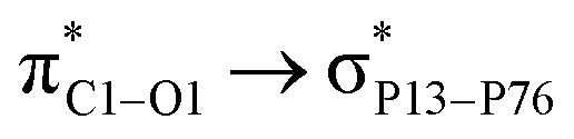 (6.99 kcal mol−1) and
  (3.10 kcal mol−1) transfers. NPNS is more electronegative than the FLU molecule, and thus electron density flows from the drug (donor) to the nanosheet (acceptor) with relatively high stabilization energy. The most important back donation from NPNS to FLU is related to the
  with an energy value of 1.11 kcal mol−1. In general, carbonyl groups of the FLU have a key role in donor–acceptor interactions and show a slight bond length increase upon the adsorption process. Total FLU → NPNS charge transfer amount is about 0.04|e|. Same to CPNS, the conductivity and other quantum parameters are not affected by nitrogen doping; thus, doping cannot improve the electrical features of PNS as a drug delivery system for the FLU molecule.