DOI:
10.1039/D2RA07883J
(Paper)
RSC Adv., 2023,
13, 5337-5352
Synthesis, characterization and application of chitosan/graphene oxide/copper ferrite nanocomposite for the adsorptive removal of anionic and cationic dyes from wastewater†
Received
9th December 2022
, Accepted 21st January 2023
First published on 13th February 2023
Abstract
The increased discharge of water pollutants drives the development of new and effective wastewater remediation methods. Herein, a magnetic nanocomposite of chitosan-graphene oxide (GO) decorated with copper ferrite (MCSGO) was synthesized under ultrasound agitation and applied to the effective removal of Safranin O (SAF) and indigo carmine (IC) dyes from wastewater. The structural, magnetic, and physicochemical features of the as-prepared MCSGO nanocomposite have been thoroughly investigated using various characterization techniques. The operational parameters such as MCSGO mass, contact time, pH, and initial dye concentration were investigated. The effects of diverse coexisting species on both dye elimination processes were examined. The experimental results demonstrated that the adsorption capacity of MCSGO nanocomposite for IC and SAF was 112.6 and 66.15 mg g−1, respectively. Five different adsorption isotherms were investigated using two-parameter (Langmuir, Tekman, and Freundlich) and three-parameter (Sips, and Redlich–Peterson) models. Thermodynamic studies revealed that the elimination of both dyes on MCSGO nanocomposite was endothermic and spontaneous, with anionic and cationic dye molecules randomly arranged onto the adsorbent nanoparticles. Moreover, the mechanism of dye elimination was deduced. Furthermore, even after five cycles of adsorption and desorption, the as-prepared nanocomposite showed no significant loss in the dye removal efficiency, indicating that it has superior stability and recycling potential.
1 Introduction
Rapid industrial development in recent decades has generated massive amounts of effluent, causing widespread concern about water pollution.1 Dyes are used in various applications including cosmetics, printing, textile coloring, and paper, among others, and they attracted great interest due to their difficult decomposition, toxicity, and direct threats to the environment and the health of living organisms.2,3 Every year, approximately 800![[thin space (1/6-em)]](https://www.rsc.org/images/entities/char_2009.gif) 000 tons of dyes are utilized worldwide; nevertheless, about 20% of dyes are wasted in the dyeing operation.4 Colored compounds and other pollutants are heavily found in effluents discharged from textile and dyeing manufacturing.5 As a result, effluents must be effectively treated before being released into the aquatic environment to eliminate these harmful substances.5 Currently, the primary methods for effluent remediation are reverse osmosis membrane, electrodialysis, photocatalysis, ion exchange, flocculation, and adsorption.6,7 However, adsorption is regarded as one of the leading approaches to wastewater remediation, owing to its low-cost, ease of operation, high efficiency, short equilibrium time and lack of sludge generation.8 Various types of adsorbents, including zeolites, functionalized silica, cellulose, magnetic nanoparticles (M-NPs), and others, have been used to remove organic dyes and other pollutants from effluent water.9–11 Nevertheless, many of the adsorbents mentioned above have some flaws in practical applications.12 Newly, carbon-based adsorbents like carbon nanotubes (CNTs), graphene oxide (GO), and activated carbon has been largely utilized for the elimination of dyes.12,13 In particular, GO has attracted researchers' interest due to its exceptional physical and chemical features; like chemical stability, electrical conductivity, huge surface area, high mechanical strength, thermal stability, and electron mobility, which have promoted its application in various disciplines.6,14 The distinctive structure and physicochemical features of GO can be assigned to the availability of a plethora of oxygen containing functional groups, e.g., hydroxyl, carboxyl, and epoxyl groups that can attract various pollutants from wastewater.5 Nevertheless, bare GO exhibited significant defects, such as the poor recovery from sludge and lower adsorptive ability due to extensive sheet stacking, among others.15 To circumvent these shortages, GO should be amended to enhance both its adsorption features and its recovery from sludge.5 Further, natural biomass is commonly used as an absorbent material due to its biodegradability, biocompatibility and availability. Chitosan (CS) is a biopolymer that is abundant in nature and is relatively cheap. Because of its biodegradability, superior antibacterial, bioactivity, anticancer, antimicrobial, antifungal actions, and biocompatibility, as well as its ability to strengthen the immune system, CS has received a lot of attention.16,17 Due to its distinctive properties, chitosan has been applied in various fields such as membrane separation, delivery systems, wound healing, wastewater treatment, and food packaging.16 Chitosan shows great adsorption ability for several types of pollutants due to the presence of its numerous hydroxyl and amino functional groups.18 Nevertheless, CS exhibit limited mechanical features and thermal stability, but these features can be promoted by impregnating CS with GO. The chitosan can be utilized as an immobilization matrix for GO, where the –OH and –NH2 of chitosan can participate in hydrogen bonding and electrostatic interactions with the surface groups of GO.19 The combination of GO and chitosan is obviously beneficial with an enhancement in the thermal, chemical, and mechanical stability of chitosan, as well as stabilizing the GO sheets and reducing their tendency to aggregate.20 The recovery of the solid adsorbent after the pollutant's removal process is one of the prime challenges in the application of sorbents. By anchoring magnetic NPs into solid sorbents, the separation and selective pollutant's removal can be achieved even in the presence of other solids.21 Due to their chemical, magnetic, and thermal features, spinel ferrites NPs are often utilized as magnetic supports for adsorbents.22 Among these spinal ferrites, CuFe2O4 has attracted substantial applied and fundamental research attention due to its numerous uses in electronics, sensors, and catalysts. In this study, we synthesized CS/GO nanocomposite and decorated it with copper ferrite magnetic NPs in one step via ultrasonic agitation and applied the as-prepared magnetic CuFe2O4/CS/GO to eliminate anionic and cationic dyes. To explore the structure and morphology of the composite sorbent materials, various spectroscopic and surface characterization techniques were applied, including XRD, BET, SEM, TEM, and FTIR. The key factors governing the dyes sorption were carefully assessed and optimized for the efficient dyes removal from wastewater. The impact of coexisting pollutants on dye elimination efficiency was investigated. Five adsorption isotherms were studied using two-parameter (Langmuir, Tekman, and Freundlich) and three-parameter (Sips, and Redlich–Peterson) models. The kinetics and thermodynamics were thoroughly investigated to elucidate the rates, and nature of dye removals onto the MCSGO. The mechanism of dye removal onto MCSGO nanocomposite was elucidated.
000 tons of dyes are utilized worldwide; nevertheless, about 20% of dyes are wasted in the dyeing operation.4 Colored compounds and other pollutants are heavily found in effluents discharged from textile and dyeing manufacturing.5 As a result, effluents must be effectively treated before being released into the aquatic environment to eliminate these harmful substances.5 Currently, the primary methods for effluent remediation are reverse osmosis membrane, electrodialysis, photocatalysis, ion exchange, flocculation, and adsorption.6,7 However, adsorption is regarded as one of the leading approaches to wastewater remediation, owing to its low-cost, ease of operation, high efficiency, short equilibrium time and lack of sludge generation.8 Various types of adsorbents, including zeolites, functionalized silica, cellulose, magnetic nanoparticles (M-NPs), and others, have been used to remove organic dyes and other pollutants from effluent water.9–11 Nevertheless, many of the adsorbents mentioned above have some flaws in practical applications.12 Newly, carbon-based adsorbents like carbon nanotubes (CNTs), graphene oxide (GO), and activated carbon has been largely utilized for the elimination of dyes.12,13 In particular, GO has attracted researchers' interest due to its exceptional physical and chemical features; like chemical stability, electrical conductivity, huge surface area, high mechanical strength, thermal stability, and electron mobility, which have promoted its application in various disciplines.6,14 The distinctive structure and physicochemical features of GO can be assigned to the availability of a plethora of oxygen containing functional groups, e.g., hydroxyl, carboxyl, and epoxyl groups that can attract various pollutants from wastewater.5 Nevertheless, bare GO exhibited significant defects, such as the poor recovery from sludge and lower adsorptive ability due to extensive sheet stacking, among others.15 To circumvent these shortages, GO should be amended to enhance both its adsorption features and its recovery from sludge.5 Further, natural biomass is commonly used as an absorbent material due to its biodegradability, biocompatibility and availability. Chitosan (CS) is a biopolymer that is abundant in nature and is relatively cheap. Because of its biodegradability, superior antibacterial, bioactivity, anticancer, antimicrobial, antifungal actions, and biocompatibility, as well as its ability to strengthen the immune system, CS has received a lot of attention.16,17 Due to its distinctive properties, chitosan has been applied in various fields such as membrane separation, delivery systems, wound healing, wastewater treatment, and food packaging.16 Chitosan shows great adsorption ability for several types of pollutants due to the presence of its numerous hydroxyl and amino functional groups.18 Nevertheless, CS exhibit limited mechanical features and thermal stability, but these features can be promoted by impregnating CS with GO. The chitosan can be utilized as an immobilization matrix for GO, where the –OH and –NH2 of chitosan can participate in hydrogen bonding and electrostatic interactions with the surface groups of GO.19 The combination of GO and chitosan is obviously beneficial with an enhancement in the thermal, chemical, and mechanical stability of chitosan, as well as stabilizing the GO sheets and reducing their tendency to aggregate.20 The recovery of the solid adsorbent after the pollutant's removal process is one of the prime challenges in the application of sorbents. By anchoring magnetic NPs into solid sorbents, the separation and selective pollutant's removal can be achieved even in the presence of other solids.21 Due to their chemical, magnetic, and thermal features, spinel ferrites NPs are often utilized as magnetic supports for adsorbents.22 Among these spinal ferrites, CuFe2O4 has attracted substantial applied and fundamental research attention due to its numerous uses in electronics, sensors, and catalysts. In this study, we synthesized CS/GO nanocomposite and decorated it with copper ferrite magnetic NPs in one step via ultrasonic agitation and applied the as-prepared magnetic CuFe2O4/CS/GO to eliminate anionic and cationic dyes. To explore the structure and morphology of the composite sorbent materials, various spectroscopic and surface characterization techniques were applied, including XRD, BET, SEM, TEM, and FTIR. The key factors governing the dyes sorption were carefully assessed and optimized for the efficient dyes removal from wastewater. The impact of coexisting pollutants on dye elimination efficiency was investigated. Five adsorption isotherms were studied using two-parameter (Langmuir, Tekman, and Freundlich) and three-parameter (Sips, and Redlich–Peterson) models. The kinetics and thermodynamics were thoroughly investigated to elucidate the rates, and nature of dye removals onto the MCSGO. The mechanism of dye removal onto MCSGO nanocomposite was elucidated.
2 Experimental work
2.1 Material and characterization
The details of the instruments, chemicals and solutions, synthesis method, and dye removal studies are given in the ESI.†
3 Results and discussion
3.1 Characterization
3.1.1 X-ray diffraction (XRD) analysis. The XRD spectra of GO, CS, copper ferrite NPs, and MCSGO composite are displayed in (Fig. 1a–d). The characteristic band of GO was located at 2θ = 9.56° with interlayer space 9.3 Å (Fig. 1a).3 While, CuFe2O4 NPs exhibited characteristic diffraction peaks at 2θ = 20.4, 30.02, 35.77, 43.9, 54.1, 58.1, and 62.4, respectively, corresponding to hkl values of (111), (220), (311), (331), (511), (422), and (440) demonstrating the felicitous synthesis of spinel copper ferrite (Fig. 1b).23 The prime band present at 2θ = 35.7 corresponds to Miller indices of (311), demonstrating that CuFe2O4 NPs have a cubic structure. Furthermore, Fig. 1c shows a distinct chitosan band at 2θ = 20.1.24 However, the characteristic peaks of GO, CuFe2O4 and CS appeared also, but with lower intensities, in the MCSGO spectrum (Fig. 1d), where the marginal decrease of GO and CS band intensities at 2θ = 9.56° and 20.1 is safely attributed to the shielding of these bands by the intense peaks of copper ferrite NPs, Fig. 1d. The XRD data demonstrated that the preparation operation did not change the copper ferrite crystallographic structure; consequentially MCSGO possesses good magnetic characteristics.
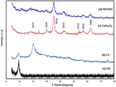 |
| | Fig. 1 XRD of (a) GO, (b) chitosan, (c) copper ferrite, and (d) MCSGO. | |
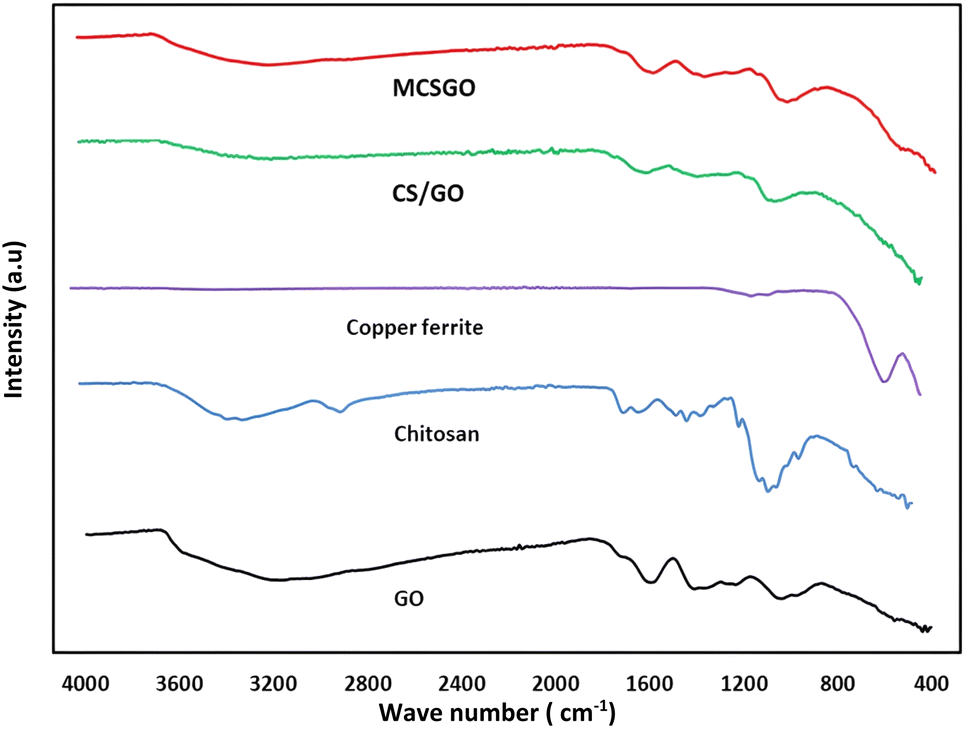
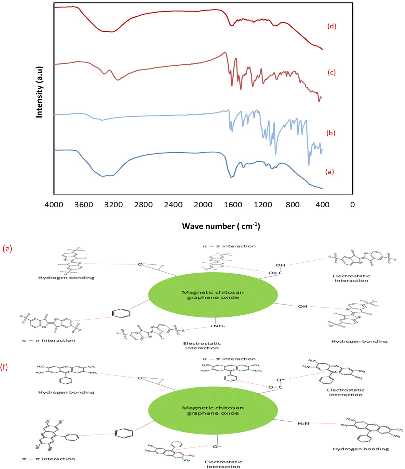
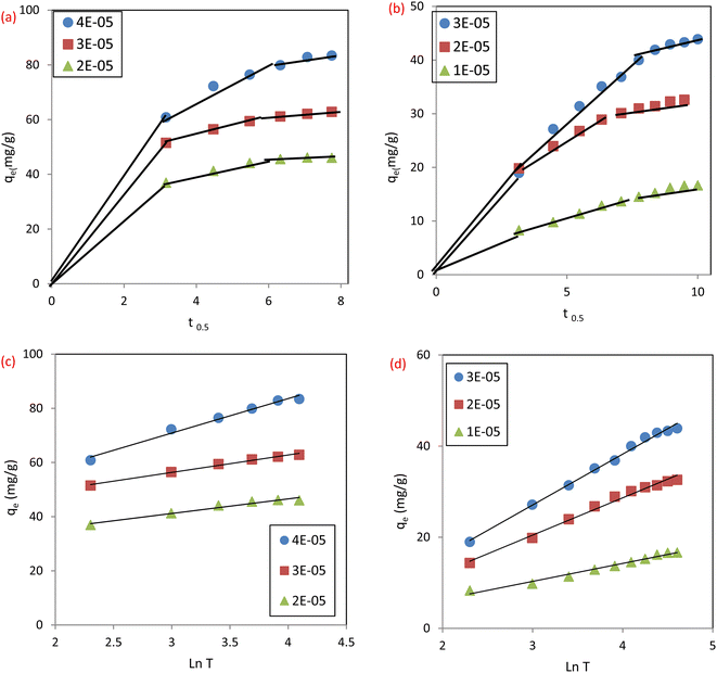
3.1.2 Fourier-Transform Infrared spectroscopic (FTIR) measurements. FTIR spectroscopy is a primary tool to characterize the functional groups of the as prepared sorbents. The FTIR spectra of GO, chitosan, CuFe2O4, CS/GO, and MCSGO are shown in Fig. 2. In the GO spectrum, the characteristic peak at 3172 cm−1 is attributed to the stretching vibrations of O–H groups; whereas the peaks at 1048, 1235, 1420, 1597, and1734 cm−1 are due to the stretching bands of alkoxy, epoxy C–O, carboxyl C–O, aromatic C![[double bond, length as m-dash]](https://www.rsc.org/images/entities/char_e001.gif) C, and CO groups, respectively. These bands are in excellent harmony with the previous report4 and confirm the successful oxidation of graphite to GO. In the chitosan spectrum, the strong peak at 3291–3361 cm−1 was assigned to N–H and O–H stretching vibrations. Whereas, the bands at 2921 and 2877 cm−1 were assigned to stretching of C–H. Furthermore, the peaks at 1645, 1589, 1325, and 1066 cm−1 are attributed to the stretching of CO of amide-I, N–H bending, stretching of C–N, and stretching of C–O, respectively.25 In the copper ferrite spectrum, the distinguished peaks at 410 and 536 cm−1 correspond to the stretching of oxygen–metal bonds in the solid sample demonstrating the felicitous synthesis of copper ferrite.26 However, after adding chitosan onto GO the intensity of all peaks is dramatically reduced due to the synergistic effects of electrostatic interaction and hydrogen bonds between negatively charged GO and polycationic sites of chitosan. In addition, in MCSGO spectrum, the appearance of a new peak at 559 cm−1 demonstrates the felicitous incorporation of CuFe2O4 onto the CS/GO composite, Fig. 2.
C, and CO groups, respectively. These bands are in excellent harmony with the previous report4 and confirm the successful oxidation of graphite to GO. In the chitosan spectrum, the strong peak at 3291–3361 cm−1 was assigned to N–H and O–H stretching vibrations. Whereas, the bands at 2921 and 2877 cm−1 were assigned to stretching of C–H. Furthermore, the peaks at 1645, 1589, 1325, and 1066 cm−1 are attributed to the stretching of CO of amide-I, N–H bending, stretching of C–N, and stretching of C–O, respectively.25 In the copper ferrite spectrum, the distinguished peaks at 410 and 536 cm−1 correspond to the stretching of oxygen–metal bonds in the solid sample demonstrating the felicitous synthesis of copper ferrite.26 However, after adding chitosan onto GO the intensity of all peaks is dramatically reduced due to the synergistic effects of electrostatic interaction and hydrogen bonds between negatively charged GO and polycationic sites of chitosan. In addition, in MCSGO spectrum, the appearance of a new peak at 559 cm−1 demonstrates the felicitous incorporation of CuFe2O4 onto the CS/GO composite, Fig. 2.
 |
| | Fig. 2 FTIR spectra of GO, chitosan, CuFe2O4, CS/GO, and MCSGO. | |
3.1.3 BET surface area analysis and BJH pore size and volume analysis. Brunauer–Emmett–Teller (BET) surface area analysis was applied to examine the porous structure and surface area of MCSGO adsorbent. As displayed in (Fig. 3a), a type-II isotherm of MCSGO NPs accompanied by a hysteresis loop at a P/P0 of 0.6–0.9 demonstrates the existence of mesoporous structures in the solid material.11 The porosity of MCSGO enhances the fast diffusion of pollutant molecules during the adsorption process, increasing the rate of reaction, and furnishing many of the active sites for the dye removal. The N2 isotherms display hysteresis loop that can be attributed to type H3 according to the IUPAC, which corresponds to slit pore shape. The determined surface area, pore diameter average and total pore volume of MCSGO were 2.9 m2 g−1, 32.8 nm, 0.0237 cm3 g−1, respectively. The Barrett–Joyner–Halenda (BJH) pore size and volume analysis, displayed in Fig. 3c, of the prepared MCSGO nanocomposite revealed that the pores present are mesoporous (2–50 nm), and little micropores. The Va-t plot (Fig. 3b) of the prepared MCSGO composite displays an upward deviation at t = 0.85 nm confirming the mesoporous nature of the MCSGO composite. Despite the fact that MCSGO exhibited a small BET surface area, it is important to note that the real surface area in water is much larger than the BET surface area as the hydrophilic polymer (chitosan) has a high swelling ability when present in water.27
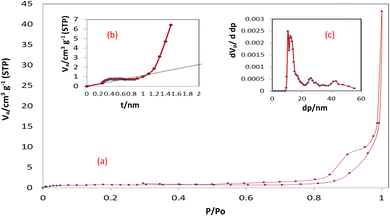 |
| | Fig. 3 (a) N2 adsorption isotherm of MCSGO, (b) t-plot, (c) BJH curve. | |
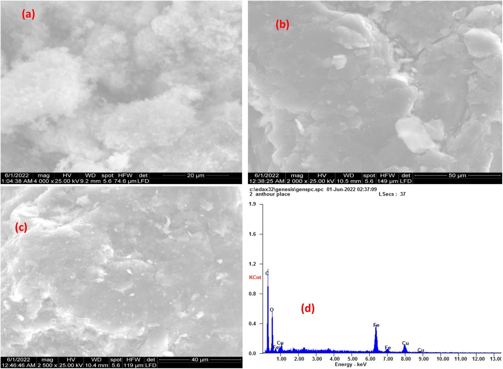
3.1.4 Scanning Electron Microscopic (SEM) analysis. The morphology of synthesized CuFe2O4, GO, and MCSGO nanocomposite is displayed in (Fig. 4a and c). The SEM micrograph, Fig. 4a, exhibited CuFe2O4 as uniformly distributed spherical particles. Furthermore, the SEM image of GO exhibited exfoliated sheets with a dense layered structure and relatively smooth surfaces as illustrated in (Fig. 4b). However, The SEM image of MCSGO, Fig. 4c, displayed nanoparticles of relatively rough surfaces covered with tiny white spots that may be attributed to CuFe2O4 nanoparticles whose presence is confirmed by EDX analysis, Fig. 4d. Moreover, the SEM micrograph of MCSGO, Fig. 4c, did not show any distinguishable layers of chitosan or GO reflecting the felicitous interaction between chitosan and GO. Furthermore, the elemental structure of MCSGO obtained from EDX analysis, Fig. 4d, displayed the distinctive peaks of C, O, Fe, and Cu demonstrating the felicitous incorporation of copper ferrite on the surface of GS/GO nanocomposite.
 |
| | Fig. 4 SEM of (a) Copper ferrite, (b) GO, (c) MCSGO, and (d) EDX of MCSGO. | |
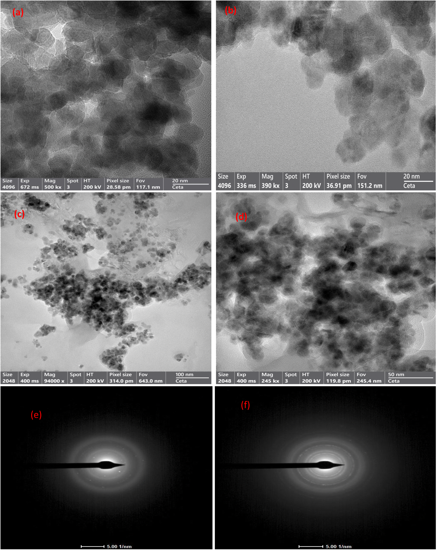
3.1.5 HRTEM-SAED analysis. The structures of CuFe2O4, GO, and MCSGO materials have been examined by high-resolution transmission electron microscopy (HRTEM) and selected area electron diffraction (SAED) analysis as represented in (Fig. 5a–f). The HRTEM micrograph, Fig. 5a, showed CuFe2O4 NPs as spheres possessing particle size of 10–17 nm. Furthermore, Fig. 5b showed GO as thick sheet-like structures with smooth surfaces. Moreover, the HRTEM images of MCSGO at different magnifications (Fig. 5c and d) illustrated the copper ferrite spheres anchored onto the interlayers of CS/GO particles, as well as, several small CS molecules felicitously assembled onto the GO surfaces with a high density. On the other hand, the SAED pattern of GO given in Fig. 5e exhibited concentric rings reflecting a polycrystalline nature related to GO, while the SAED pattern of MCSGO (Fig. 5f) shows major planes (220), (311), and (400), which manifests the incorporation of CuFe2O4 NPs onto the CS/GO nanocomposite.
 |
| | Fig. 5 HRTEM image of (a) Copper ferrite, (b) GO, (c and d) MCSGO, and SEAD of (e) GO, and (f) MCSGO. | |
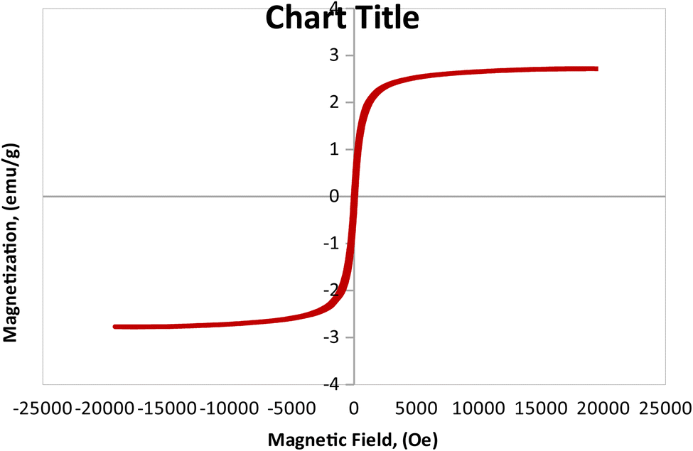
3.1.6 Vibrating sample magnetometer (VSM) analysis. The magnetic features of the as-synthesized MCSGO adsorbent has been investigated at room temperature, using VSM analysis as illustrated in Fig. 6 that exhibited a characteristic S-like VSM hysteresis loop demonstrating a typical ferromagnetic features of the prepared MCSGO nanocomposite. The synthesized MCSGO possesses a magnetization saturation (Ms) of 2.71 emu/g that is adequate for the fast recovery of MCSGO after a typical adsorption operation.
 |
| | Fig. 6 Vibrating sample magnetometer analysis of MCSGO. | |
3.2 Batch adsorption
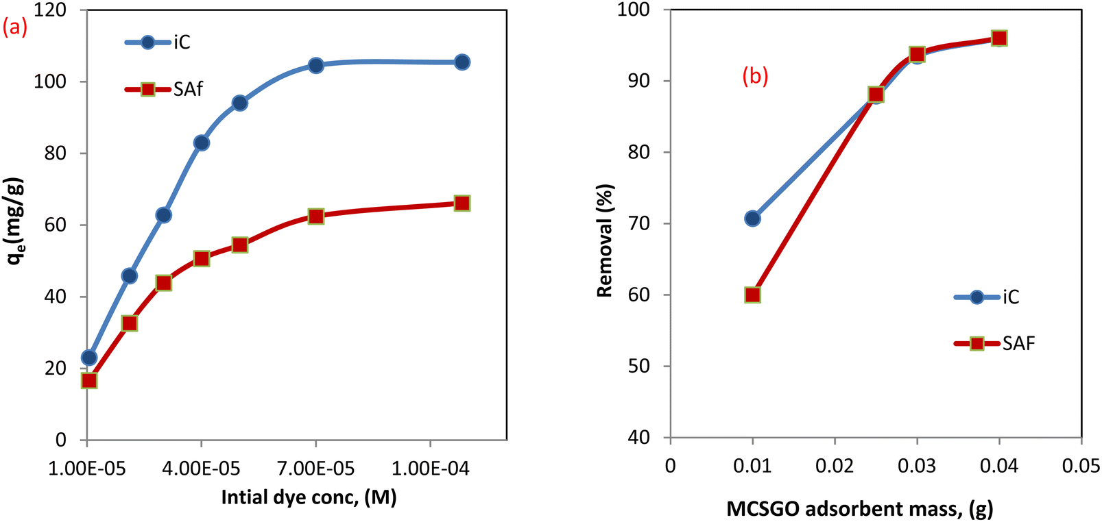
3.2.1 Effect of initial dye concentration. The concentration of sorbate pollutants played a fundamental role as a fixed weight of the MCSGO nanocomposite sorbent can eliminate a maximum fixed amount of sorbate dye. The effect of the initial concentrations of anionic (IC) and cationic (SAF) dyes were studied using a 100 ml dye solution containing 1 × 10⁻⁵ to 1 × 10⁻⁴ M and determining the adsorption capacity of IC and SAF onto the MCSGO nanocomposite. The obtained results demonstrated that the adsorption capacity increased as the initial dye concentration increased,28 as shown in Fig. 7a. Higher dye concentrations result in greater removal capabilities driven by the reduced resistance of dye molecules transfer from the solution to the active adsorption sites of the MCSGO nanocomposite3 Nevertheless, the % removal is reduced due to the consumption of unoccupied sites by the dye molecules.
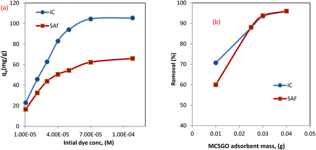 |
| | Fig. 7 (a) Effect of initial dye concentration, (b) effect of adsorbent weight. | |
3.2.2 Effect of MCSGO adsorbent mass. To examine the effect of the MCSGO mass on IC and SAF dyes' elimination efficiency, the adsorbent mass was increased from 0.01 to 0.04 g per 100 ml of the dye solution while maintaining other experimental parameters constant, Fig. 7b. The obtained data demonstrated that the IC and SAF dyes removal% increased from 70.7 to 95.91% and 60.1 to 96.0% by increasing the adsorbent mass from 0.01 to 0.04 g/100 ml for IC and SAF, respectively. That enhancement in elimination efficiency of IC and SAF with the rise of the adsorbent mass is ascribed to the present abundance of the vacant sites and functional groups on the surfaces of MCSGO nanocomposite particles.4 A nonlinear enhancement in the percentage of elimination with increasing composite mass may be because of agglomeration of composite particles or a low number of dye molecules medium.
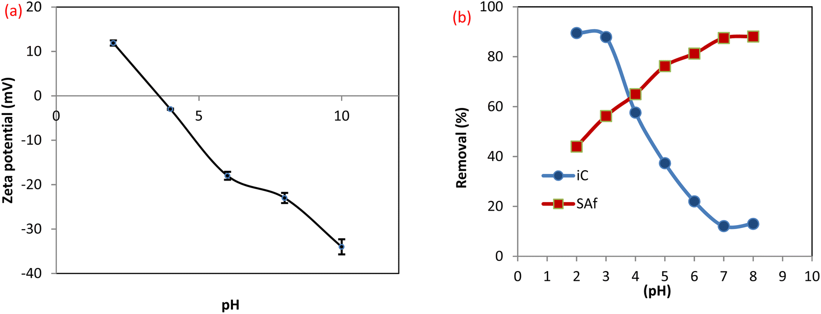
3.2.3 Effect of pH on dye removal efficiency. The surface charge of MCSGO adsorbent and the structures of dye molecules are affected by the solution pH, which is a key factor controlling the adsorption mechanism.26 The zeta potential value has been determined at diverse points in the range of 2.0–10.0 as displayed in Fig. 8a. The isoelectric point (IEP) of the MCSGO composite is 3.8, which means that the MCSGO surface does not bear any electric charge at that point, while the surface becomes negatively charged at pH points higher than the IEP and positively charged when the pH of the medium is less than the IEP.4 As shown in Fig. 8b, the maximum removal was observed at pH 7.0 for SAF (88.13%) and pH 3 for IC dye (87.86%). For the SAF dye, there was a gradual reduction in the removal efficiency of the dye with a decrease in the pH value. This is due to the repulsion between the positive surface of the MCSGO and the cationic dye molecule.28 Also, in an acidic medium, an excessive amount of H+ surrounding the surface of the compound increases their competitions with SAF, which in turn decreases the uptake of the dye.29 Furthermore, the removal of the cationic SAF dye at low pH values can be ascribed to the hydrogen bonding and π–π interactions.30 When the medium becomes more alkaline, the removal of the SAF dye shows a corresponding increase. This is related to the significant electrostatic attraction among the positively charged nitrogen of the SAF dye with the deprotonated groups on the MCSGO surface as well as the π–π force.11 In contrast, the removal efficiency of IC dye is significantly enhanced at low pH values. The electrostatic forces that occur at low pH values between the negatively charged dye and MCSGO can be attributed to the presence of protons of GO surface groups, or amido groups in MCSGO that resulted from the interaction of amino groups in CS with GO carboxyl groups.30 Furthermore, the removal of the anionic IC dye above IEP value can be ascribed to the hydrogen bonding and π–π interactions. However, the decrease in removal efficiency with increasing pH value can be assigned to the repulsion force between similarly charged groups.
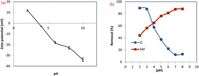 |
| | Fig. 8 (a) Zeta potential of MCSGO, (b) effect of pH on the dye removal efficiency. | |
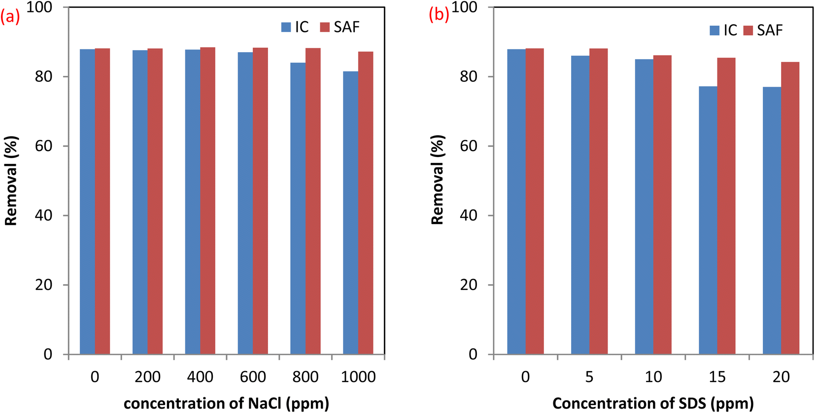
3.2.4 Effect of coexisting species. Effluents of dyeing processes contain different substances such as surfactants as a model organic pollutant and dissolved salts like NaCl that are common coexisting species. The presence of these substances may affect the efficiency of dyes removal using the MCSGO nanocomposite. Therefore, we examined the effects of NaCl and SDS on the elimination efficiency of SAF and IC dyes using the MCSGO adsorbent. Fig. 9a and b show the effects of the presence of 0–1000 ppm NaCl and 0–20 ppm SDS on the SAF and IC dye elimination efficiency using the MCSGO adsorbent. It can be noticed that the elimination efficiency of SAF dye is unaffected by the addition of the electrolyte. Furthermore, higher concentrations of the electrolyte exhibited a slight effect on the removal efficiency of IC dye, Fig. 9a. On the other hand, the addition of SDS had no effect on the removal of SAF dye; however, the observed slight decrease in the elimination efficiency of IC dye (Fig. 9b) was attributed to the competition of the anionic SDS head groups with the anionic IC molecules towards the active adsorption sites of MCSGO adsorbent.
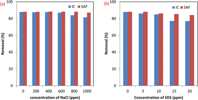 |
| | Fig. 9 Effect of coexistence material (a) NaCl, and (b) SDS surfactant. | |
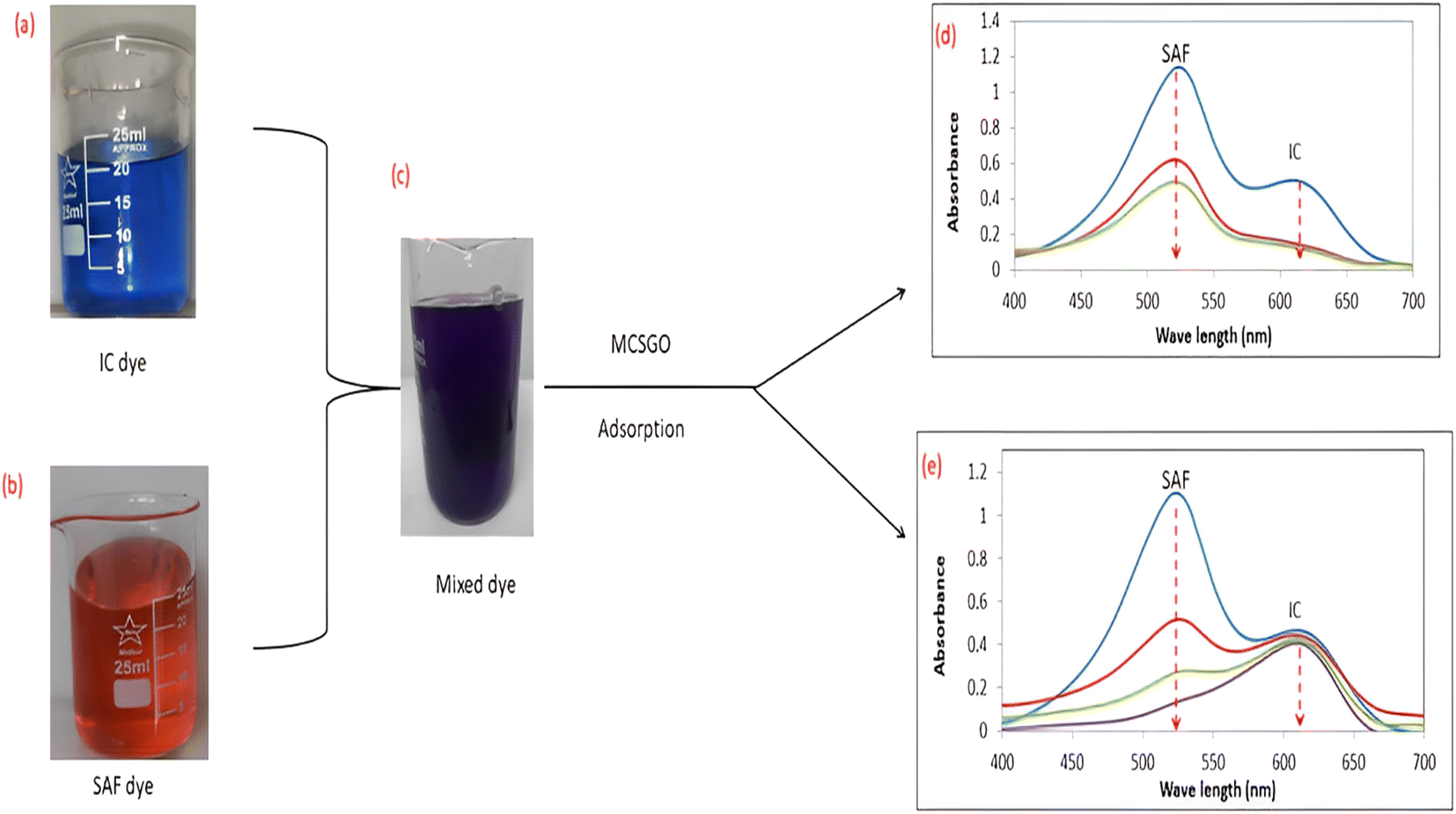
3.2.5 Adsorption performance in binary system of dyes. In practice, wastewaters frequently contain mixtures of several dyes; therefore, the adsorptive removal of mixtures of IC anionic and SAF cationic dyes were examined at the optimum pH values of 3.0 and 7.0, respectively. Images of dye solutions before and after mixing and the UV-vis spectral data before and after the adsorptive removal process are shown in Fig. 10a–e. The UV spectra of Fig. 10d showed that at pH 3.0, the MCSGO nanocomposite succeeded in removing the entire IC dye and 60% of the SAS, while at pH 7.0, Fig. 10e, it successfully removed SAF dye and only a small percentage of IC dye. These results revealed that the presence of more than one dye does not affect the adsorption features of the prepared nanocomposite. However, the selectivity and efficiency in removing dye pollutants are governed by the solution pH, as explained in section 3.2.3.
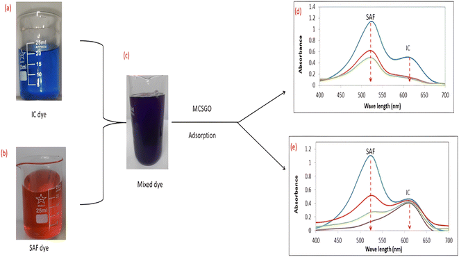 |
| | Fig. 10 (a, b, and c) Optical images and (d and e) UV-vis spectra of the mixed solution of IC and Safranin dye before and after the adsorption by MCSGO adsorbent. | |
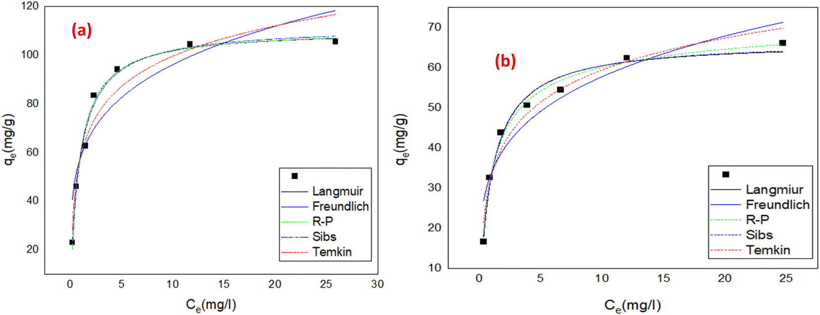
3.3 Adsorption isotherms
The relationship between the equilibrium concentrations of adsorbate in solution (Ce) and that adsorbed on the solid adsorbent (qe), at constant temperature, is represented by a curve known as an adsorption isotherm. The adsorption isotherm is useful for analyzing a variety of important aspects of pollutant removal operations, such as the type of removal mechanism, the nature of adsorbate layers formed on the adsorbent surfaces, interaction between the adsorbent and adsorbate, and the number of adsorbate molecules distributed in the pores and covering the entire surface of the adsorbent. Five equilibrium isotherms were examined using two-parameters (Langmuir, Tekman, and Freundlich) and three-parameter (Sips, and Redlich–Peterson) models. OriginLab software and both non-linear forms (graphs shown) and linear forms (graphs not shown) were utilized for data correlations, calculation of each model's parameters, and estimation of the best fits correlation coefficients, as displayed in Table 1.
Table 1 Adsorption isotherms parameters
| Models |
IC dye |
SUF dye |
| Langmuir model |
| qmax (mg g−1) |
110.42 |
66.5 |
| b (L mg−1) |
1.17 |
0.985 |
| R2 |
0.988 |
0.981 |
| RL |
0.017–0.151 |
0.026–0.215 |
|
| Freundlich model |
| R2 |
0.85 |
0.87 |
| Kf |
58.08 |
33.7 |
| n |
4.56 |
4.28 |
|
| Temkin |
| B |
17.96 |
11.5 |
| Kt (L g−1) |
25.5 |
17.3 |
| b (J mol−1) |
98.19 |
217.7 |
| R2 |
0.929 |
0.95 |
|
| Redlich–Peterson isotherm |
| bR |
0.98 |
0.95 |
| aR |
1.182 |
1.34 |
| KR |
130 |
78 |
| Qe qm |
109.98 |
58.2 |
| R2 |
0.983 |
0.983 |
|
| Sips isotherm |
| qm |
111.9 |
66.8 |
| ks |
0.82 |
0.88 |
| ms |
0.80 |
0.93 |
| R2 |
0.985 |
0.98 |
3.3.1 Langmuir isotherm. The Langmuir theory15 assumes that a contaminates elimination proceeds through monolayer adsorption onto definite homogeneous positions on the surfaces of the adsorbent and can be represent mathematically by nonlinear eqn (1):| |
 | (1) |
Where ‘qe and qm’ are the equilibrium and maximum quantities (mg g−1) of the dye that can be removed by the prepared adsorbent, ‘Ce’ is the remaining dye concentration (mg L−1) after achieving equilibrium, and b is the Langmuir constant (L mg−1). Fig. 11a and b display the Langmuir model graphs for IC and SAF removal onto MCSGO nanocomposite. Furthermore, Table 1 shows the Langmuir model's parameters, where qm values were 110.42 mg g−1, and 66.5 mg g−1 and the correlation coefficients R2 were 0.981 and 0.981 for IC and SAF, respectively, demonstrating that the IC and SAF dyes' elimination follows the Langmuir model with the formation of monolayers onto the surfaces of MCSGO nanoparticles. The favorableness of the dye's elimination process was ascertained from the RL factor, which was acquired from the Langmuir isotherm using eqn (2):15| |
 | (2) |
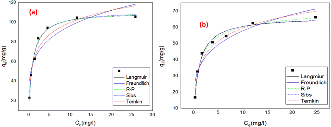 |
| | Fig. 11 Nonlinear forms of adsorption isotherms for (a) the removal of IC dye on MCSGO, and (b) the removal of SAF dye on MCSGO. | |
The estimated RL values were 0.017–0.15 and 0.026–0.215 (0 < RL <1) for the elimination of IC and SAF dyes, respectively, demonstrating the great interaction of the IC and SAF molecules with the MCSGO nanoparticles and the favorableness of the dyes removal process.
3.3.2 Freundlich isotherm. The Freundlich isotherm takes into account multilayer adsorption as well as a heterogeneous dispersion of active sites, and can be represent mathematically by eqn (3):4| |
 | (3) |
Where Ce is remaining equilibrium concentration of dye adsorbate, Kf is the Freundlich's constant in (mg g−1), and n is the Freundlich exponent related to the intensity of the adsorption; it is dimensionless. Freundlich's graph for the elimination of IC and SAF on MCSGO composite is displayed in Fig. 11a and b. When the value of “n” is greater than 1, this demonstrates that the adsorbate removal process is favorable. The values of n for the removal of IC and SAF dyes on MCSGO composite were 4.6 and 4.2, respectively, demonstrating that the dyes' elimination process is favorable. The high values of Kf demonstrate the strong binding of IC and SAF dyes onto the MCSGO nanocomposite; Table 1 shows the Freundlich constants.
3.3.3 Temkin model. Temkin's model takes into account the indirect adsorbate/adsorbate interactions as well as the adsorbate/adsorbent interactions, in addition to the heat of adsorption. The model presumes that as the % elimination increases, the heat of adsorption of all molecules in the layer decreases linearly as a result of increase of the surface coverage, and the nonlinear equation is given by:| |
 | (4) |
Where Kt is the Temkin isotherm constant (L g−1) related to binding energy, Ce (mg L−1) is the equilibrium concentration, and b is Temkin constant corresponding to the heat of adsorption (J mol−1). The Temkin isotherm parameters are displayed in Table 1. The determined values of the heat of adsorption of IC and SAF dye removal onto the MCSGO adsorbent were 98.19 and 217 J mol−1, respectively, reflecting the endothermic nature of IC and SAF dye elimination process.
3.3.4 Sips model. This model is a combined form of Freundlich and Langmuir isotherms and is more appropriate to elucidate the adsorption operation on surfaces of heterogeneous nature. It forecasts the Langmuir isotherm at great pollutant concentrations and the Freundlich isotherm at low pollutant concentrations. The nonlinear form can be expressed as:31| |
 | (5) |
Where, kS is the Sips constant, qe (mg g−1) is the equilibrium adsorption capacity, Ce (mg g−1) is the equilibrium concentration of IC adsorbate dye, and ms is the Sips model exponent. The Sips isotherm parameters are shown in the Table 1. The value of R2 of the nonlinear plot for the removal of IC and SAF dye onto MCSGO is 0.985, and 0.984, respectively; reflecting that the model is suitable to describe the adsorption operation. The value of n for the elimination of IC and SAF dyes onto MCSGO approached 1.0, and the calculated adsorption capacity is 111.9 and 66.8 mg g−1 for IC and SAF dyes, respectively; which are close to that calculated from Langmuir isotherm, demonstrating that the elimination is more suitable with the Langmuir isotherm than the Freundlich isotherm.
3.3.5 Redlich–Peterson isotherm. The R–P isotherm is an empirical model that includes the features of both Freundlich and Langmuir isotherms. Three parameters are included in this empirical isotherm model. At large concentrations, the R–P model approach that of Freundlich while at low concentrations it approaches the Henry's law. It incorporates elements of the Freundlich and Langmuir equations; hence the removal mechanism is a combination, as it varies from the ideal to the multilayer adsorption behavior. The linear equation of the Redlich–Peterson model can be represented as:32| |
 | (6) |
Where KR (L g−1), aR (L g−1), and bR are the R–P constants, qe (mg g−1) adsorption capacity, and Ce (mg g−1) is the final equilibrium concentration of adsorbate at equilibrium. The bR is an exponent that ranges from 0 to 1. Thus, if the value of bR is outside 0–1, the data will not be adequately explained by the R–P equation. The ratio of KR/aR reflects the adsorption capacity. The R–P isotherm parameters are shown in the Table 1. The value of bR for the elimination of IC and SAF dyes onto the as-prepared MCSGO approached 1.0, which demonstrates that the elimination is more suitable with the Langmuir isotherm than with the Freundlich isotherm.
3.4 Kinetic studies
The mechanisms, rate-controlling steps, and ideal conditions of pollutant's elimination can be visualized using kinetic modeling of adsorption data. Various kinetic models are commonly applied to adsorptive removal processes, including the pseudo-first-order (PFO), pseudo-second-order (PSO), intraparticle diffusion (IPD), and Elovich models.
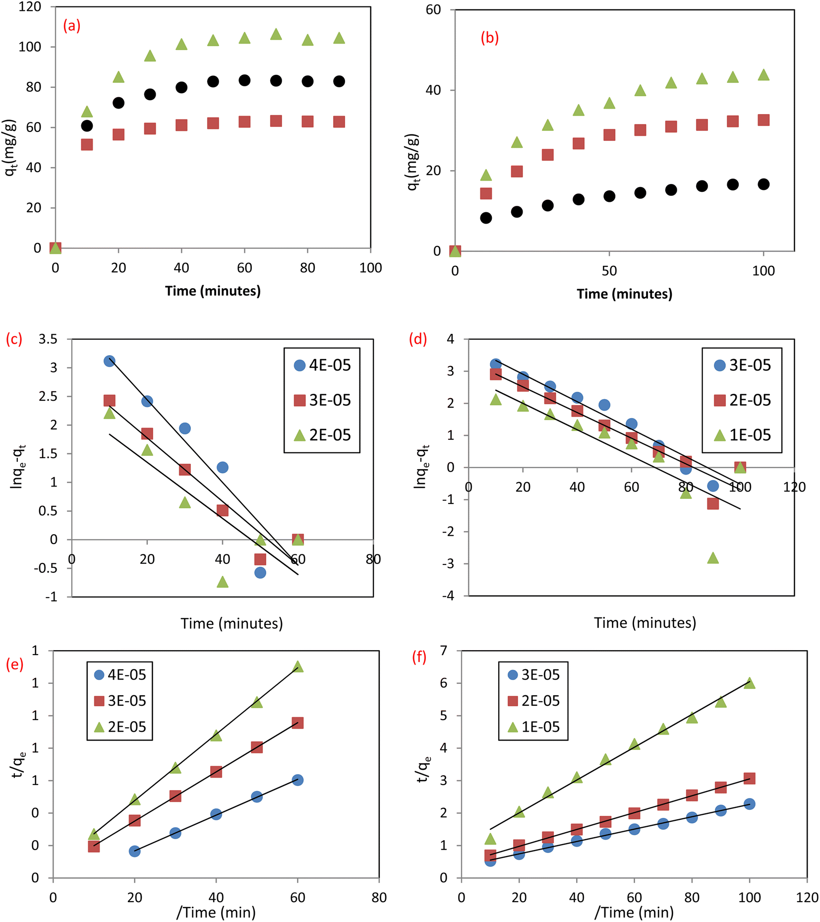
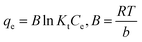
3.4.1 Pseudo first order (PFO) and pseudo second order) PSO). The contact time is a critical parameter in the adsorption process, where quick elimination of pollutants and attainment of equilibrium in a short time display the adsorbent efficiency in eliminating the studied pollutants.4 The effect of time on the uptake of SAF and IC dyes by MCSGO NPs is illustrated in Fig. 12a and b, respectively. It was observed that the elimination of dyes was quick in the first ten minutes and reached equilibrium after 60 and 100 minutes for IC and SAF, respectively. The fast dye removal at the initial stage of the adsorption process can be assigned to the presence of several vacant sites distributed over the nanocomposite surfaces. However, in the last stage of the adsorption process, the rate of dye removal becomes much slower,33 probably due to the significant reduction in the number of vacant sites on the surfaces of MCSGO NPs and/or the agglomeration of these particles.3 The obtained adsorption data of IC and SAF dyes onto the MCSGO nanocomposite were fitted, Fig. 12c and d, according to the PFO and PSO models, respectively. It was observed that the R2 values of the PFO fitting had small values, Table 2, demonstrating that this kinetic model cannot be applied to explain the dyes elimination process.4 Nevertheless, the qm values estimated from PSO graphs, Fig. 12e and f, for the elimination of both IC and SAF dyes were very close to the experimental qm values. Moreover, the high R2 values demonstrated that the PSO kinetic model was predominant, and controlled the adsorptive removal of IC and SAF dyes onto the MCSGO nanocomposite. These findings show that the dye elimination occurred first through film diffusion, then through a gradual progression of the adsorption process, and finally reached equilibrium.26
 |
| | Fig. 12 Effect of contact time for the removal of (a) IC dye, and (b) SAF dye; PFO plots for the removal of (c) IC dye; and (d) SAF dye, and PSO plots for the removal of (e) IC dye, and (f) SAF dye. | |
Table 2 Adsorption kinetics parameters
| Models |
IC dye |
SAF |
| 4 × 10⁻⁵ M |
3 × 10⁻⁵ M |
2 × 10⁻⁵ M |
3 × 10⁻⁵ M |
2 × 10⁻⁵ M |
1 × 10⁻⁵ M |
| Pseudo first order |
| qe (experiment) |
83.42 |
62.80 |
46.02 |
43.88 |
32.6 |
16.64 |
| qe (calculated) |
48.5 |
17.9 |
10.2 |
43.0 |
27.0 |
16.7 |
| R2 |
0.89 |
0.92 |
0.69 |
0.94 |
0.91 |
0.69 |
|
| Pseudo second order |
| qe (experiment) |
83.42 |
62.80 |
46.02 |
43.88 |
32.6 |
16.64 |
| qe (calculated) |
90.0 |
65.7 |
48.7 |
52.6 |
38.4 |
19.8 |
| R2 |
0.99 |
0.99 |
0.99 |
0.99 |
0.99 |
0.99 |
|
| Weber- Morris (IPD) |
| K (mg g−1min−0.5) |
4.8 |
2.4 |
2.03 |
3.5 |
2.6 |
1.2 |
| C |
48.2 |
44.8 |
31.7 |
10.7 |
8.5 |
4.3 |
|
| Elovich model |
| α (mg g−1 min−1) |
166 |
2090 |
560 |
6.25 |
4.95 |
2.68 |
| β (g mg−1) |
0.078 |
0.15 |
0.185 |
0.089 |
0.122 |
0.25 |
| R2 |
0.98 |
0.99 |
0.96 |
0.99 |
0.98 |
0.98 |
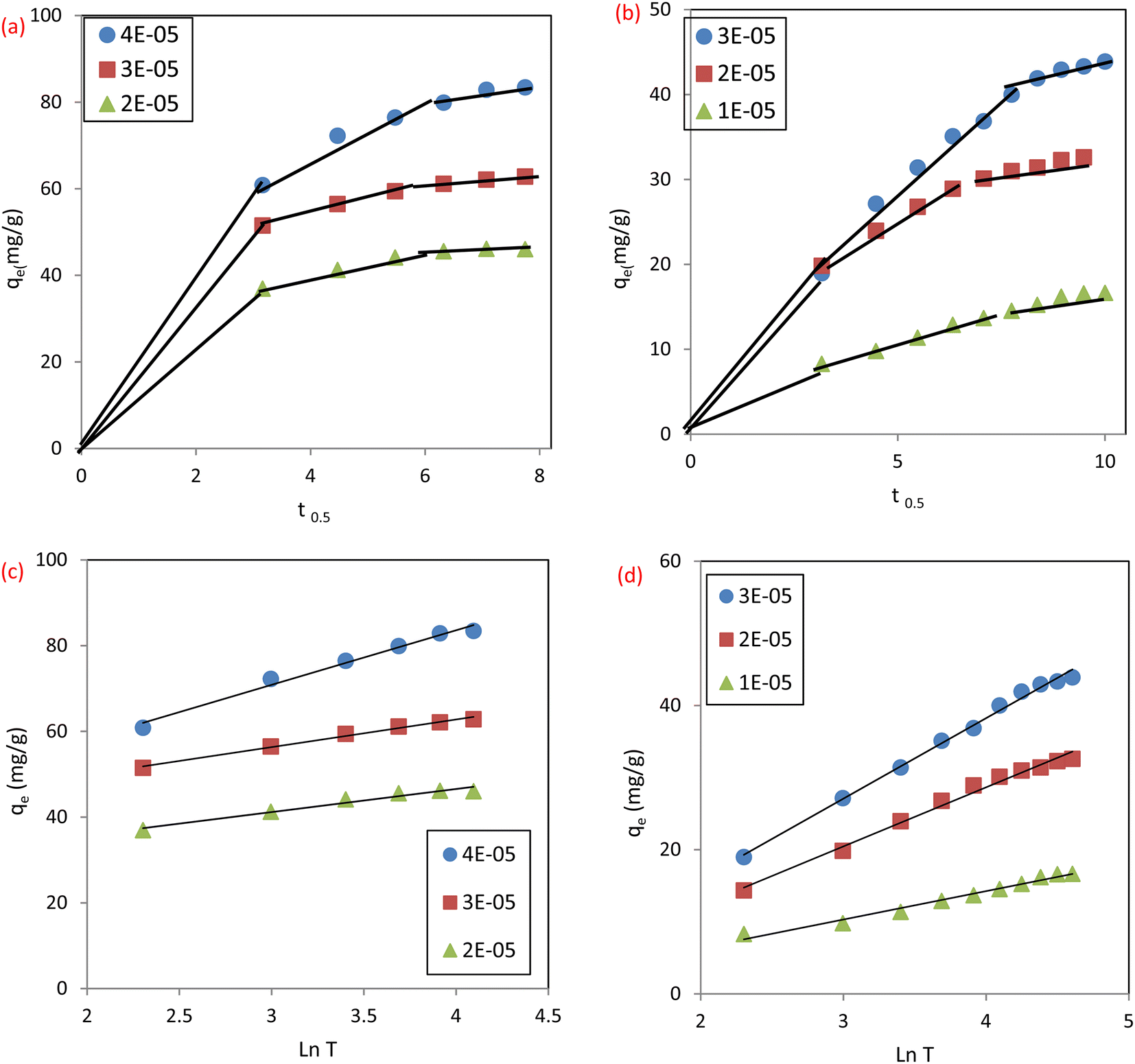
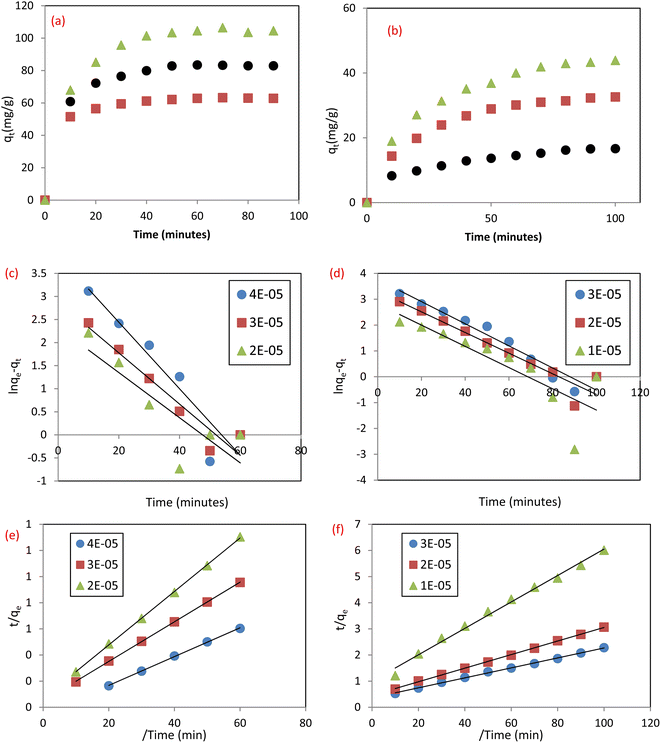
3.4.2 Intraparticle diffusion (IPD). In order to better understand how sorbate molecules are transported from solution to the adsorbent surfaces, Weber Morris developed the intraparticle diffusion model (IPD),34 eqn (7):Where C (mg g−1) is the intercept and gives details about the boundary layer thickness, Kid is the rate constant of intraparticle diffusion (mg g−1 min−1/2). Thus, multi-linear graphs were obtained, Fig. 13a and b, for the adsorption of IC and SAF dyes on MCSGO nanocomposite demonstrating that more than one single mechanism influenced the dye removal process. The sharper parts of the plots can be attributed to the external diffusion of dyes from the bulk of the solution to the surfaces of MCSGO NPs. The other linear part is attributed to the diffusion of dyes deep into the MCSGO NPs. The values of Kid and C demonstrated that intraparticle diffusion and film diffusion took place independently, with appreciable participation of film diffusion.
 |
| | Fig. 13 The plots of intraparticle diffusion model for the removal of (a) IC dye, (b) SAF dye: and of Elovich model for the removal of (c) IC dye and (d) SAF dye. | |
3.4.3 Elovich model. The Elovich model assumes an increase in activation energy with adsorption time on heterogeneous adsorbent surfaces and was used to describe the exponential decrease in adsorption rate with increasing adsorbate amount, and is expressed by eqn (8):| |
 | (8) |
Where qt is the amount of pollutant adsorbed (mg g−1) by the MCSGO at a time t, β is the desorption constant (g mg−1), and α is the initial adsorption rate (mg g−1 min−1). Application of Elovich equation and the corresponding curves and parameters are shown in Fig. 13c and d and Table 2 that revealed the excellent fitting of experimental data with the Elovich model. Comparing the data fitting of PFO, PSO, IPD, and Elovich kinetic models, revealed that the elimination process of IC and SAF dyes onto the MCSGO solid adsorbent is a complex process that is influenced by various factors, including the chemisorption stage, the concentration of adsorbent, intra-particle diffusion stage, and slow chemical diffusion, whereas the chemisorption stage is the rate-determining step. In addition, the PSO and Elovich models exhibited the best–fit correlation coefficient among the examined models and was observed to give a realistic explanation of the removal kinetics of IC and SAF dyes.
3.5 Adsorption thermodynamics
Temperature is also one of the essential factors influencing a sorbate adsorption process. To estimate the main thermodynamics parameters, the effect of temperature on the elimination of IC and SAF dyes onto MCSGO must also be examined. Important thermodynamic parameters, such as the enthalpy change (ΔH, kJ mol−1), Gibbs free energy (ΔG, kJ mol−1), and entropy change (ΔS, kJ kmol−1) provide valuable information for visualizing the adsorption mechanism, feasibility, and spontaneity of the adsorption process.4 The experimental results showed that as the medium temperature increased from 293 K to 308 K, the elimination of IC and SAF dyes increased due to increased collisions between the active adsorption sites of MCSGO composite and the dyes molecules, resulting in an increase in adsorption capacity. Thermodynamic parameters can be estimated using the following equations:15| |
 | (9) |
| | |
ΔG0 = −RTlnKc
| (10) |
Where, T is absolute temperature, qe in adsorption capacity (mg g−1), Kc is the equilibrium constant; and R is the general gas constant. The linear plot of lnK against 1/T for the elimination of IC and SAF dyes onto MCSGOO composite was shown in Fig. S1.† Based on the data reported in Table 3, the positive value of ΔH demonstrated the endothermic nature of the elimination operation of IC and SAF dyes onto MCSGO NPs. The ΔS demonstrated enhanced randomness arrangement of dye molecules onto MCSGO NPs through the adsorption operation. The negative sign of ΔG values reflected that the elimination operation process is spontaneous, feasible, and becomes more favorable as the temperature rises. Furthermore, the ΔG values are in the range of 0 and 20 kJ, which indicating that the elimination of IC and SAF dyes on MCSGO was mainly a physical process.35
Table 3 Adsorption thermodynamics parameters
| Dye |
Temp (K) |
ΔG0 (kJ mol−1) |
ΔH0 (kJ mol−1) |
ΔS0 (kJ mol−1) |
| IC dye |
293 |
−4.2 |
33.8 |
0.0141 |
| 298 |
−4.9 |
| 303 |
−5.5 |
| 308 |
−5.9 |
| SUF dye |
303 |
−4.6 |
22.4 |
0.090 |
| 308 |
−4.8 |
| 313 |
−5.3 |
| 318 |
−5.8 |
3.6 Adsorption mechanism
Investigation of pH showed that the electrostatic interaction plays a vital role in removing dyes from the MCSGO adsorbents (Fig. 7b). Further, the elimination mechanism of dyes on MCSGO composite was deduced guided by experimental data including as the FTIR spectra of MCSGO before (Fig. 2) and after the IC and SAF dye removal operation (Fig. 14a and d). For example, the FTIR spectrum of MCSGO after IC removal exhibited flattening the metal-oxygen band at 536 cm−1 due to dye-MCSGO interactions. Furthermore, the intensity of the board peak at 3200 cm−1 increased and shifted to higher wave number reflecting the interaction between the dye and MCSGO particles via H-bonding.36,37 Moreover, the symmetric stretching band of the SO3− group shifted to 1099 cm−1, which reflects the participation of SO3− groups in IC adsorption on MCSGO.36 The peak at 1576 cm−1 in the MCSGO composite completely disappeared after adsorption indicating that the π–π interaction plays an essential role in the dye removal process. Moreover, the intensity of the bands increased at 1456 cm−1 and 996 cm−1 indicating the presence of SO and S–O stretching due to the IC dye containing SO3− structures, which confirms the adsorption of the IC on the surfaces of MCSGO NPs.38 In the case of MCSGO–SAF (Fig. 14d), the band at 536 cm−1 corresponding to metal oxygen bond was shifted to a lower wave number of 526 cm−1. The broad band around 3400 cm is assigned to vibration formed by hydrogen bonds formed between MCSGO and SAF dye molecules.37 Moreover, the new peaks that occurred in 1601 and 1630 cm−1 can be assigned to the aromatic rings of dye molecules, while the peaks at 1450, and 1327 cm−1 can be assigned to CH3 bending and aromatic C–N vibrations, respectively.39 These results demonstrated that the removal of IC and SAF dyes on MCSGO proceeded through electrostatic interaction, H-bonding, and π–π interactions. The proposed mechanism of IC and SAF dye adsorptive elimination onto the MCSGO NPs is illustrated in Fig. 14e and f.
 |
| | Fig. 14 (a) FTIR spectra of MCSGO loaded with IC dye, (b) IC dye, (c) SAF dye, and (d) MCSGO loaded with SAF dye; and the proposed adsorption mechanism of removing (e) SAF dye, and (f) IC dye. | |
3.7 Comparative studies
The adsorption capacity of the as-prepared MCSGO nanocomposite was compared with representative adsorbents employed to eliminate IC and SAF dyes as shown in Table 4, where, the MCSGO nanocomposite exhibited outstanding adsorbent capacity.
Table 4 Comparative study of adsorption capacities of the current MCGO and other adsorbents
| Adsorbent |
Adsorption capacity (mg g−1) |
Ref. |
| IC dye |
SAF dye |
| MCSGO |
110.4 |
66.5 |
Current work |
| Chitosan |
71.82 |
— |
40 |
| Zeolite |
1.23 |
— |
41 |
| Silk |
18.3 |
— |
42 |
| MgFe2O4 |
46.08 |
— |
26 |
| Activated sewage sludge |
60.04 |
— |
43 |
| LDH |
55.5 |
— |
44 |
| Montmorillonite |
40 |
— |
45 |
| SDS/RM |
— |
89.4 |
46 |
| Ferruginous kaolinite |
— |
59.3 |
47 |
| Rice husk (NaOH treated) |
— |
9.77 |
48 |
| Pineapple peels |
— |
21.7 |
49 |
| Mango seed integuments (untreated) |
|
34.4 |
50 |
| Mango seed integuments (NaOH treated) |
|
43.1 |
|
| Magnetically modified coffee grounds |
|
59.0 |
51 |
| Pineapple peels |
|
26.8 |
52 |
3.8 Regeneration of MCSGO adsorbent
Reusability serves as a metric for determining the ideal adsorbent. The adsorbent regeneration and reuse for several consecutive cycles can significantly reduce the overall cost of effluent remediation. Therefore, the MCSGO composite was tested for five consecutive cycles in a batch experiment as shown in Fig. S2,† where it was regenerated by 0.02 mol L−1 HCL as eluent for SAF and 0.02 mol L−1 NaOH for IC dye, respectively. The observed slight reduction in the removal efficiency was attributed to the slight gradual loss of vacant sites of adsorbent as the regeneration cycles progressed.
4 Conclusion
In this study, the elimination of IC anionic and SAF cationic dyes were effectively achieved onto the as-prepared MCSGO nanocomposite. The felicitous preparation of MCSGO composite was ascertained by various techniques including XRD, SEM, EDX, HRTEM, SAED, VSM, FTIR, BET and zeta potential studies. The morphological analysis of the MCSGO composite displayed that copper ferrite NPs were felicitously anchored on CS/GO hybrid sheets. Experimental data demonstrated that the removal of IC and SAF dyes was significantly improved with increasing the contact time, initial dye concentration, and adsorbent mass. The removal efficiency of dyes was not significantly affected by the presence of coexisting materials of NaCl and SDS, while the selectivity of dyes removal depends on the pH value of the solution. The elimination of dyes on MCSGO essentially follows the Langmuir model demonstrating monolayer formation on the surface of MCSGO. Furthermore, the removal kinetics followed the PSO mechanism. Both intra-particle diffusion and film formation were also involved in the dye removal process. The obtained values of thermodynamic parameters demonstrated that dyes' removal was endothermic as well as a random arrangement of dye molecules on MCSGO surfaces. FTIR analyses give information on main functional groups and bonds in the MCSGO composite, demonstrating that surface groups and aromatic structures participate in dyes elimination through electrostatic interaction, π–π interactions and H-bonding. Finally, MCSGO composite was proved to be highly efficient, easily recoverable, and promising sorbent for the removal of anionic and cationic dyes from effluent.
Conflicts of interest
There are no conflicts to declare.
References
- P. Gharbani and A. Mehrizad, Preparation and characterization of graphitic carbon nitrides/polyvinylidene fluoride adsorptive membrane modified with chitosan for Rhodamine B dye removal from water: Adsorption isotherms, kinetics and thermodynamics, Carbohydr. Polym., 2022, 277, 118860 CrossRef CAS PubMed.
- A. Tkaczyk, K. Mitrowska and A. Posyniak, Synthetic organic dyes as contaminants of the aquatic environment and their implications for ecosystems: A review, Sci. Total Environ., 2020, 717, 137222 CrossRef CAS PubMed.
- M. A. Ahmed and A. A. Mohamed, A systematic review of layered double hydroxide-based materials for environmental remediation of heavy metals and dye pollutants, Inorg. Chem. Commun., 2022, 110325 Search PubMed.
- M. A. Ahmed, M. A. Ahmed and A. A. Mohamed, Facile adsorptive removal of dyes and heavy metals from wastewaters using magnetic nanocomposite of zinc ferrite@ reduced graphene oxide, Inorg. Chem. Commun., 2022, 144, 109912 CrossRef CAS.
- M. Adel, et al., Removal of heavy metals and dyes from wastewater using graphene oxide-based nanomaterials: A critical review, Environ. Nanotechnol., Monit. Manage., 2022, 18, 100719 CAS.
- M. A. Ahmed and A. A. Mohamed, Recent progress in semiconductor/graphene photocatalysts: synthesis, photocatalytic applications, and challenges, RSC advances, 2023, 13(1), 421–439 RSC.
- M. Adel, et al., Characterization of fouling for a full-scale seawater reverse osmosis plant on the Mediterranean sea: membrane autopsy and chemical cleaning efficiency, Groundwater for Sustainable Development, 2022, 16, 100704 CrossRef.
- J. Xiong, et al., Amphiprotic cellulose mediated graphene oxide magnetic aerogels for water remediation, Chem. Eng. J., 2020, 400, 125890 CrossRef CAS.
- R. Guo, et al., Sandwiched Fe3O4/carboxylate graphene oxide nanostructures constructed by layer-by-layer assembly for highly efficient and magnetically recyclable dye removal, ACS Sustainable Chem. Eng., 2018, 6(1), 1279–1288 CrossRef CAS.
- J. Yan, et al., A magnetically recyclable magnetic graphite oxide composite functionalized with polydopamine and β-cyclodextrin for cationic dyes wastewater remediation: Investigation on adsorption performance, reusability and adsorption mechanism, Appl. Surf. Sci., 2022, 602, 154338 CrossRef CAS.
- M. Adel, M. A. Ahmed and A. A. Mohamed, Effective removal of cationic dyes from aqueous solutions using reduced graphene oxide functionalized with manganese ferrite nanoparticles, Compos. Commun., 2020, 22, 100450 CrossRef.
- M. Sultana, et al., A review on experimental chemically modified activated carbon to enhance dye and heavy metals adsorption, Cleaner Engineering and Technology, 2022, 6, 100382 CrossRef.
- S. S. Qureshi, et al., Microwave-assisted synthesis of carbon nanotubes for the removal of toxic cationic dyes from textile wastewater, J. Mol. Liq., 2022, 356, 119045 CrossRef CAS.
- S. Velusamy, et al., A review on heavy metal ions and containing dyes removal through graphene oxide-based adsorption strategies for textile wastewater treatment, Chem. Rec., 2021, 21(7), 1570–1610 CrossRef CAS PubMed.
- M. Adel, M. A. Ahmed and A. A. Mohamed, A facile and rapid removal of cationic dyes using hierarchically porous reduced graphene oxide decorated with manganese ferrite, FlatChem, 2021, 26, 100233 CrossRef CAS.
- H. Ali, A. Ismail and A. Menazea, Multifunctional Ag/ZnO/chitosan ternary bio-nanocomposites synthesized via laser ablation with enhanced optical, antibacterial, and catalytic characteristics, J. Water Process. Eng., 2022, 49, 102940 CrossRef.
- T. Jiao, et al., Self-assembly reduced graphene oxide nanosheet hydrogel fabrication by anchorage of chitosan/silver and its potential efficient application toward dye degradation for wastewater treatments, ACS Sustainable Chem. Eng., 2015, 3(12), 3130–3139 CrossRef CAS.
- L. Fan, et al., Fabrication of novel magnetic chitosan grafted with graphene oxide to enhance adsorption properties for methyl blue, J. Hazard. Mater., 2012, 215, 272–279 CrossRef PubMed.
- D. C. d. S. Alves, et al., Graphene-based materials immobilized within chitosan: applications as adsorbents for the removal of aquatic pollutants, Materials, 2021, 14(13), 3655 CrossRef CAS PubMed.
- H. Karimi-Maleh, et al., Recent advances in using of chitosan-based adsorbents for removal of pharmaceutical contaminants: A review, J. Cleaner Prod., 2021, 291, 125880 CrossRef CAS.
- R. Ramadan and A. Ismail, Tunning the Physical Properties of PVDF/PVC/Zinc Ferrite Nanocomposites Films for More Efficient Adsorption of Cd (II), J. Inorg. Organomet. Polym. Mater., 2022, 32(3), 984–998 CrossRef CAS.
- D. H. K. Reddy and Y.-S. Yun, Spinel ferrite magnetic adsorbents: alternative future materials for water purification?, Coord. Chem. Rev., 2016, 315, 90–111 CrossRef CAS.
- B. R. Vergis, et al., Comparison of magnetic
and dielectric properties of transition metal nanospinel ferrites, MFe2O4,(M= Co, Cu, Ni, Zn) synthesized by one-pot combustion route, Mater. Today: Proc., 2022, 49, 870–877 Search PubMed.
- J. Shah and M. R. Jan, Magnetic chitosan graphene oxide composite for solid phase extraction of phenylurea herbicides, Carbohydr. Polym., 2018, 199, 461–472 CrossRef CAS PubMed.
- M. F. Queiroz, et al., Does the use of chitosan contribute to oxalate kidney stone formation?, Mar. Drugs, 2014, 13(1), 141–158 CrossRef PubMed.
- M. Adel, M. A. Ahmed and A. A. Mohamed, Effective removal of indigo carmine dye from wastewaters by adsorption onto mesoporous magnesium ferrite nanoparticles, Environ. Nanotechnol., Monit. Manage., 2021, 16, 100550 CAS.
- S. Mallakpour, Z. Radfar and M. Feiz, Optimization of chitosan/tannic acid@ ZnFe layered double hydroxide bionanocomposite film for removal of reactive blue 4 using a response surface methodology, Int. J. Biol. Macromol., 2022, 209, 747–762 CrossRef CAS PubMed.
- M. Adel, M. A. Ahmed and A. A. Mohamed, Synthesis and characterization of magnetically separable and recyclable crumbled MgFe2O4/reduced graphene oxide nanoparticles for removal of methylene blue dye from aqueous solutions, J. Phys. Chem. Solids, 2021, 149, 109760 CrossRef CAS.
- S. Ghorai, et al., Enhanced removal of methylene blue and methyl violet dyes from aqueous solution using a nanocomposite of hydrolyzed polyacrylamide grafted xanthan gum and incorporated nanosilica, ACS Appl. Mater. Interfaces, 2014, 6(7), 4766–4777 CrossRef CAS PubMed.
- K. Gul, et al., Functionalization of magnetic chitosan with graphene oxide for removal of cationic and anionic dyes from aqueous solution, Carbohydr. Polym., 2016, 152, 520–531 CrossRef CAS PubMed.
- G. V. Brião, et al., Highly efficient and reusable mesoporous zeolite synthetized from a biopolymer for cationic dyes adsorption, Colloids Surf., A, 2018, 556, 43–50 CrossRef.
- L. Meili, et al., Adsorption of methylene blue on agroindustrial wastes: experimental investigation and phenomenological modelling, Prog. Biophys. Mol. Biol., 2019, 141, 60–71 CrossRef CAS PubMed.
- H. Ali, T. M. Tiama and A. Ismail, New and efficient NiO/chitosan/polyvinyl alcohol nanocomposites as antibacterial and dye adsorptive films, Int. J. Biol. Macromol., 2021, 186, 278–288 CrossRef CAS PubMed.
- W. J. Weber Jr and J. C. Morris, Kinetics of adsorption on carbon from solution, Journal of the Sanitary Engineering Division, 1963, 89(2), 31–59 CrossRef.
- Q. Li, et al., Equilibrium, thermodynamics and process design to minimize adsorbent amount for the adsorption of acid dyes onto cationic polymer-loaded bentonite, Chem. Eng. J., 2010, 158(3), 489–497 CrossRef CAS.
- M. Nagpal and R. Kakkar, Facile synthesis of mesoporous magnesium oxide–graphene oxide composite for efficient and highly selective adsorption of hazardous anionic dyes, Res. Chem. Intermed., 2020, 46(5), 2497–2521 CrossRef CAS.
- Z. H. Dastgerdi, S. S. Meshkat and M. D. Esrafili, Enhanced adsorptive removal of Indigo carmine dye performance by functionalized carbon nanotubes based adsorbents from aqueous solution: equilibrium, kinetic, and DFT study, J. Nanostruct. Chem., 2019, 9(4), 323–334 CrossRef CAS.
- L. Hevira, J. O. Ighalo and R. Zein, Biosorption of indigo carmine from aqueous solution by Terminalia catappa shell, J. Environ. Chem. Eng., 2020, 8(5), 104290 CrossRef CAS.
- M. K. Sahu, U. K. Sahu and R. K. Patel, Adsorption of safranin-O dye on CO 2 neutralized activated red mud waste: process modelling, analysis and optimization using statistical design, RSC Adv., 2015, 5(53), 42294–42304 RSC.
- A. G. Prado, et al., Comparative adsorption studies of indigo carmine dye on chitin and chitosan, J. Colloid Interface Sci., 2004, 277(1), 43–47 CrossRef CAS PubMed.
- T. de Carvalho, et al., Adsorption of indigo carmine from aqueous solution using coal fly ash and zeolite from fly ash, J. Radioanal. Nucl. Chem., 2011, 289(2), 617–626 CrossRef.
- N. Jiwalak, et al., Equilibrium and kinetic modeling of the adsorption of indigo carmine onto silk, Fibers Polym., 2010, 11(4), 572–579 CrossRef CAS.
- M. Otero, et al., Elimination of organic water pollutants using adsorbents obtained from sewage sludge, Dyes Pigm., 2003, 57(1), 55–65 CrossRef CAS.
- M. Ahmed and A. Mohamed, An efficient adsorption of indigo carmine dye from aqueous solution on mesoporous Mg/Fe layered double hydroxide nanoparticles prepared by controlled sol-gel route, Chemosphere, 2017, 174, 280–288 CrossRef CAS PubMed.
- F. Geyikçi, Factorial design analysis for
adsorption of Indigo Carmine onto Montmorillonite-Evaluation of the kinetics and equilibrium data, Prog. Org. Coat., 2016, 98, 28–34 CrossRef.
- M. K. Sahu and R. K. Patel, Removal of safranin-O dye from aqueous solution using modified red mud: kinetics and equilibrium studies, RSC Adv., 2015, 5(96), 78491–78501 RSC.
- M. R. Abukhadra, M. A. El-Meligy and A. M. El-Sherbeeny, Evaluation and characterization of Egyptian ferruginous kaolinite as adsorbent and heterogeneous catalyst for effective removal of safranin-O cationic dye from water, Arabian J. Geosci., 2020, 13(4), 1–13 CrossRef.
- S. Chowdhury, et al., Optimum sorption isotherm by linear and nonlinear methods for safranin onto alkali-treated rice husk, Biorem. J., 2011, 15(2), 77–89 CrossRef CAS.
- M. Mohammed, A. Ibrahim and A. Shitu, Batch removal of hazardous safranin-O in wastewater using pineapple peels as an agricultural waste based adsorbent, Int. J. Environ. Monit. Anal., 2014, 2(3), 128–133 CAS.
- M. R. Malekbala, et al., Equilibrium and kinetic studies of safranine adsorption on alkali-treated mango seed integuments, Int. J. Chem. Eng. Appl., 2012, 3(3), 160–166 CAS.
- I. Safarik, et al., Magnetically modified spent coffee grounds for dyes removal, Eur. Food Res. Technol., 2012, 234(2), 345–350 CrossRef CAS.
- M. Yusuf, F. M. Elfghi and S. K. Mallak Malaysia, Kinetic studies of safranin-O removal from aqueous solutions using pineapple peelsIranian (Iranica), J. Energy Environ., 2015, 6(3), 173–180 Search PubMed.
|
| This journal is © The Royal Society of Chemistry 2023 |
Click here to see how this site uses Cookies. View our privacy policy here. 
 Open Access Article
 This Open Access Article is licensed under a Creative Commons Attribution-Non Commercial 3.0 Unported Licence
 *,
Mohamed A. Ahmed
*,
Mohamed A. Ahmed