
 Open Access Article
 This Open Access Article is licensed under a Creative Commons Attribution-Non Commercial 3.0 Unported Licence
Cycling stability of Fe2O3 nanosheets as supercapacitor sheet electrodes enhanced by MgFe2O4 nanoparticles
Guanlun Guo a,
Qiwei Sua,
Wei Zhouc,
Mingrui Wei*a and
Yun Wang*b
a,
Qiwei Sua,
Wei Zhouc,
Mingrui Wei*a and
Yun Wang*b
aHubei Key Laboratory of Advanced Technology for Automotive Components, Hubei Research Center for New Energy & Intelligent Connected Vehicle, Wuhan University of Technology, Wuhan 430070, China
bHubei University of Arts and Science, Xiangyang, 441053, China. E-mail: 1295355658@qq.com
cInstitute of Electronic Engineering, Chinese Academy of Engineering Physics, Mianyang 621000, China
First published on 25th January 2023
Abstract
The Fe2O3 material is a common active material for supercapacitor electrodes and has received much attention due to its cheap and easy availability and high initial specific capacitance. In the present study, we prepared adhesive-free Fe2O3 sheet electrodes for supercapacitors by growing Fe2O3 material on nickel foam by hydrothermal method. The sheet electrode exhibited a high initial specific capacitance of 863 F g−1, but we found that the sheet lost its specific capacitance too quickly through cyclic stability tests. To solve this problem, Fe2O3/MgFe2O4 composites were grown on nickel foam (NF). It was found through testing that the cycling stability of the sheet electrode gradually increased as the content of MgFe2O4 material increased. When the molar ratio of Fe2O3 to MgFe2O4 material was 1![[thin space (1/6-em)]](https://www.rsc.org/images/entities/char_2009.gif) :1, the initial specific capacitance of the sheet electrode was 815 F g−1 and the capacitance remained at 81.25% of the initial specific capacitance after 1000 cycles. The better cycling stability results from the more stable structure of the composite, the synergistic effect leading to better reversibility of the reaction.
:1, the initial specific capacitance of the sheet electrode was 815 F g−1 and the capacitance remained at 81.25% of the initial specific capacitance after 1000 cycles. The better cycling stability results from the more stable structure of the composite, the synergistic effect leading to better reversibility of the reaction.
1. Introduction
The increasing environmental problems have led to a growing interest in new and clean energy sources. As the most common secondary energy, energy storage technologies for electrical energy have been extensively researched.1–3 Among the large number of available energy storage technologies, the most promising are lithium-ion batteries and ultracapacitors. Supercapacitors fill the performance gap between batteries and capacitors by offering energy and power densities between them, storing more energy than conventional capacitors, and having a higher cycle life, higher multiplier performance and better stability than batteries.4–6 These advantages give supercapacitors a wide range of application scenarios and are attracting widespread interest.Supercapacitors mainly consist of electrodes, electrolyte and diaphragm, where the electrodes play a crucial role in the performance of the supercapacitor. In the case of electrodes, the active material determines the performance and energy storage mechanism.7–9 Depending on the energy storage mechanism, supercapacitors are usually classified as double layer capacitors and pseudocapacitors.10,11 For capacitors where only physical adsorption and desorption of ions is present, they are known as double-layer capacitors and the representative electrode material is porous carbon. Although the energy density of double layer capacitors is generally low, their high cycling stability and excellent performance at high multipliers show their great value.12–15 Capacitors with reversible Faraday reactions are known as pseudocapacitors and are represented by metal oxides and conducting polymers. Compared to double-layer capacitors, pseudocapacitors have a higher energy density, but also a significantly lower cycle life.16–19 Fe2O3 is a common metal oxide, a cheap and abundant material in nature. Like other metal oxides, iron oxide has excellent electrochemical properties, but as an electrode material, iron oxide has the fatal drawbacks of low initial Coulomb efficiency and rapid decay during charge/discharge cycling, which leads to the current limitation of the application of iron oxide materials in sheet electrode.20–22 The reason for the rapid decay of iron oxide properties is its poor electrical conductivity and excessive volume change, which we usually control its size to improve its volume change problem and thus enhance the cycling stability. In order to overcome the defects of metal oxides, a number of effective strategies have been investigated, such as polymer coatings,23 the introduction of carbon materials24 and the construction of heterogeneous interfaces.25 And we have found that by compounding materials, a synergistic effect can be created, which can enhance cycling stability when used as an electrode material. MgFe2O4 is an anti-spinel structure material, which is often used in the study of magnetism because of its excellent magnetic properties.26–28 In the field of electrochemistry, MgFe2O4 is not used enough, and some scholars have generated electrode materials with better cycling stability by combining metal oxides with MgFe2O4.29–31
In this paper, Fe2O3/MgFe2O4 materials were synthesised in one step using a simple hydrothermal method and grown directly on nickel foam. Through electrochemical tests, we found that the Fe2O3/MgFe2O4 sheet electrode has better cycling stability and multiplicative performance compared to the Fe2O3 sheet electrode. We have explored the effect of MgFe2O4 materials on the performance of sheet electrodes and analysed the reasons for their improved stability by comparing different content of sheet electrode materials through material characterisation and physical property analysis.
2. Experimental Section
2.1 Preparation of Fe2O3 sheet electrode
Fe2O3 sheet electrodes were synthesized by hydrothermal method, and the Fe2O3 material is grown directly on nickel foam, no adhesive or subsequent treatment is required All chemical reagents used in this paper were of analytical purity and do not require further purification. 2 mmol of Fe(NO3)3·9H2O and 12 mmol of urea were dissolved in 30 ml of deionized water, and stirred with a magnetic stirrer for 30 minutes at room temperature to form a homogeneous golden solution, and then the liquid was transferred into a polytetrafluoroethylene (PTFE). A piece of nickel foam was ultrasonically cleaned with acetone, ethanol and deionised water in turn for ten minutes to remove oil and impurities, and cut to a size of 2 cm × 2 cm. The nickel foam is placed vertically in the PTFE liner and immersed in the solution. The reaction was carried out in an autoclave at 120 °C for 6 h. The obtained reddish-brown sheet electrode was washed with deionised water to remove the deposited material from the surface. After calcination at 300 °C for 120 minutes at a heating rate of 2 °C, the sheet electrode was prepared. The sample was labelled as FM-0.2.2 Preparation of Fe2O3/MgFe2O4 sheet electrode
By adding 0.2 mmol, 0.5 mmol and 1 mmol Mg(NO3)2·6H2O to 2 mmol Fe(NO3)3·9H2O and 12 mmol urea, respectively, without changing other conditions, different ratios of Fe2O3/MgFe2O4 complexes were produced, which were recorded as FM-1, FM-2 and FM-3, respectively, and the ratios of Fe2O3 and MgFe2O4 were to be 8:2, 5:5 and 0:10, respectively. Specific information on all samples is shown in Table 1. The preparation process of Fe2O3 and Fe2O3/MgFe2O4 sheet electrodes is shown in Fig. 1.
| Sample | Amount (mmol) | Molar ratio of Fe2O3 and MgFe2O4 | |
|---|---|---|---|
| Fe(NO3)3·9H2O | Mg(NO3)2·6H2O | ||
| FM-0 | 2 | 0 | 10:0 |
| FM-1 | 2 | 0.2 | 8:2 |
| FM-2 | 2 | 0.5 | 5:5 |
| FM-3 | 2 | 1 | 0:10 |
 | ||
| Fig. 1 Preparation process of Fe2O3 and Fe2O3/MgFe2O4 sheet electrodes. | ||
2.3 Materials character and electrochemical measurements
All samples were analysed in phase by X-ray diffraction (XRD, Bruker D8 Advance). The product morphology of FM-0 and FM-2 were characterized by scanning electron microscope (SEM, Zeiss Gemini 300). Chemical composition and material binding mode of FM-2 samples were characterized by transmission electron microscopy (TEM, Tecnai G2 F30). The distribution of Fe and Mg elements in FM-2 sample were characterized by energy dispersive spectrometer (EDS). Full spectral characterisation of FM-2 sample and the analysis of Fe2+/Fe3+ content of FM-0 and FM-2 samples before and after cycle testing were characterized by X-ray photoelectron spectroscopy (XPS, Thermo Scientific K-Alpha). The specific surface area and pore size of the FM-0 and FM-2 loading materials were obtained by N2 adsorption and desorption experiments (ASAP 2460), and the electrical conductivity of FM-0, FM-2 and FM-3 was obtained by a resistivity testing (RTS-9).The electrochemical properties of all samples were tested using a three-electrode system with the sample electrode as the working electrode, the platinum wire as the counter electrode, the Hg/HgO as the reference electrode and the electrolyte using 1 M KOH. Cyclic voltammetry (CV), constant current charge/discharge and cyclic stability tests were carried out on all samples. The GCD test is used to calculate the specific capacitance and is based on the following equation:32
 | (1) |
3. Results and discussion
3.1 Materials composition analysis
To prove the synthetic substance composition, we performed XRD and XPS analysis on these materials. We scraped off and collected the loaded material from the nickel foam and carried out XRD tests on this loaded material. Fig. 2(a) shows the XRD patterns of all samples. For the FM-0 sample, all diffraction peaks can be corresponded to JCPDS no. 89-0597 card. For sample FM-1, we can see that the peak at 2θ = 35.587° is already much higher than the 2θ = 33.117° for the Fe2O3 material, demonstrating the presence of XRD peaks for other substances that can correspond to the crystalline plane of MgFe2O4 (3 3 1), as well as XRD peaks at 2θ = 43.253° and 62.828°, corresponding to the (4 0 0) and (4 4 0) planes. For sample FM-2, there are additional XRD peaks at 2θ = 30.212° and 37.227° corresponding to the (2 2 0) and (2 2 2) crystallographic planes of MgFe2O4 due to the increased MgFe2O4 content. Fig. 2(b) shows full spectrum for X-ray electron spectroscopy. The principle of the XPS test is to de-radiate the sample with X-rays so that the electrons or valence electrons within the atoms are excited and detected. As the different elements have different binding energies, a qualitative analysis of these elements can be carried out. The peaks corresponding to the elements Mg, Fe and O can be observed in this graph, which proves the presence of these elements in the sample.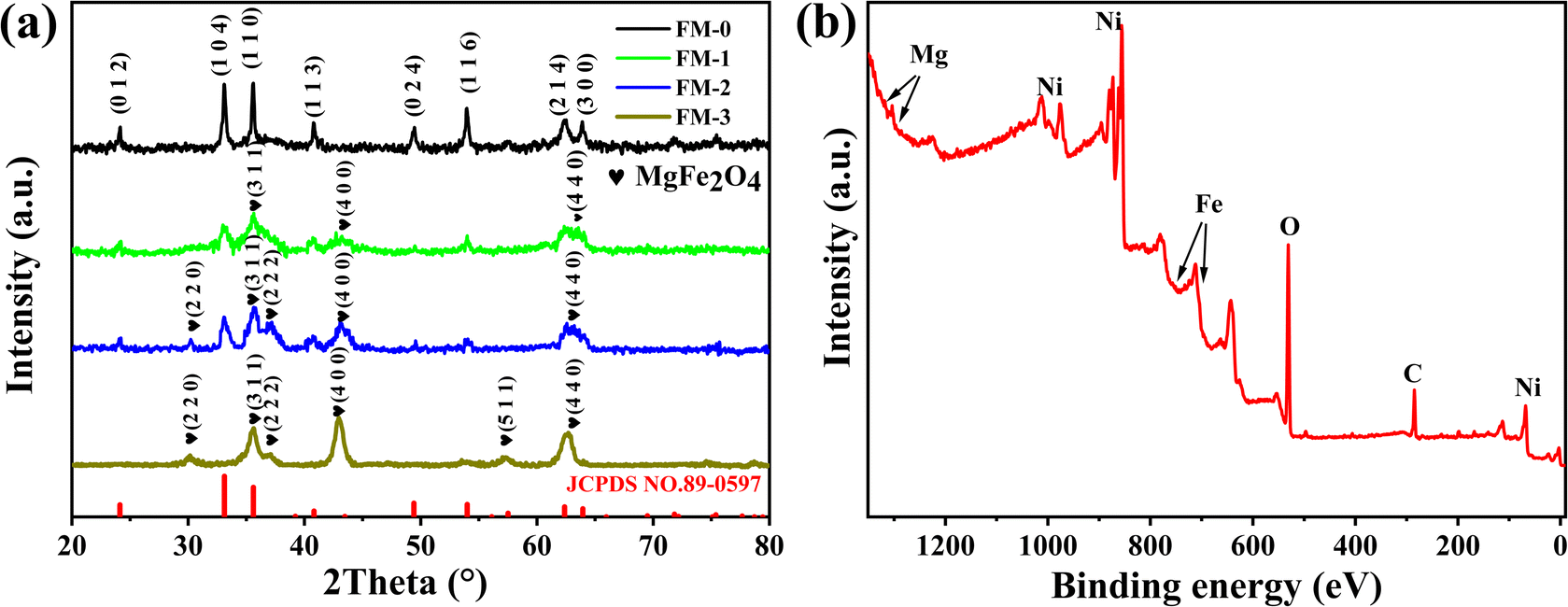 | ||
| Fig. 2 (a) XRD curves of loaded material for samples FM-0 to FM-3. (b) XPS full spectrum of FM-2. | ||
3.2 Electrochemical analysis
We performed electrochemical tests on samples FM-0 to FM-3 in a three-electrode system with 1 M KOH as the electrolyte, and the results are shown in Fig. 3. Fig. 3(a–d) show the cyclic voltammetry (CV) curves of FM-0 to FM-2 at scan rates of 10, 20, 30, 50 mV s−1. All the curves have distinct redox peaks, indicating the pseudo-capacitance of the Fe2O3 material, which is attributed to the iron ion conversion between Fe2+ and Fe3+.33–35 As the scan rate increases, the CV curves maintain their basic shape respectively, indicating their general reversibility. Comparing Fig. 3(a–c), for the FM-0 sample, the oxidation peak of the CV curve shifted from a potential of 0.55 V to over 0.65 V at a scan rate of 10 mV versus 50 mV with an offset of greater than 0.1 V, and the reduction peak shifted from approximately 0.37 V to 0.28 V with an offset of approximately 0.09 V. For the FM-2 sample, the oxidation peak shifted from approximately 0.5 V to 0.55 V with an offset of approximately 0.05 V, while the reduction peak was only about 0.04 V. It can be obtained that the peak shift becomes smaller as the amount of MgFe2O4 material compounded increases, which indicates that the irreversible reaction in the reaction decreases at high scan rates as the MgFe2O4 material is compounded.36,37 The better the reversibility of the reaction the better the stability of the reaction. From Fig. 3(d), it can be found that the reduction peak potential of the MgFe2O4 material is higher, located at 0.45 V at 10 mV s−1 and shifted to 0.38 V at 50 mV s−1, with an offset of about 0.07 V. This indicates that as the MgFe2O4 content in the Fe2O3/MgFe2O4 composite increases, a synergistic effect occurs between the two materials, leading to a reversible reaction better. Fig. 3(f–h) shows the galvanostatic charge–discharge (GCD) curves for FM-0 to FM-3 at current densities of 1–8 A g−1. The specific capacitance of FM-0 to FM-2 is calculated to be as high as 863 F g−1, 842 F g−1 and 815 F g−1 at a current density of 1 A g−1. The high specific capacitance benefits from an adhesive-free sheet electrode synthesis process in which nickel foam acts as a template to control the growth of the material, producing better morphology and providing a more uniform loading than hand-applied electrode activators. This process also eliminates the need for adhesives, reducing the impact of adhesion on performance.38–40 Fig. 3(i) shows the charge/discharge curves for the FM-0 to FM-2 samples at a current density of 1 A g−1. As can be seen from the figure, the charging capacity of all samples is less than the charging capacity, and the charging/discharging efficiency of the electrode sheet increases with the addition of MgFe2O4 material, with 83% and 84% efficiency for FM-0 to FM-2 respectively, while the FM-2 sample has a higher efficiency of 87%. The same synergistic effect is seen in the electrical conductivity. The conductivity tests of samples FM-0, FM-2 and FM-3 are shown in Table 2. The thicknesses of FM-0, FM-2 and FM-3 were 0.351 mm, 0.326 mm and 0.372 mm respectively, with the FM-2 sample having the smallest thickness. The conductivity was 2500 s cm−1, 5000 s cm−1 and 3333 s cm−1, respectively, which shows that the conductivity of the MgFe2O4 electrode sheet is higher than that of the Fe2O3 electrode sheet, and the Fe2O3/MgFe2O4 composite can have higher conductivity than both materials.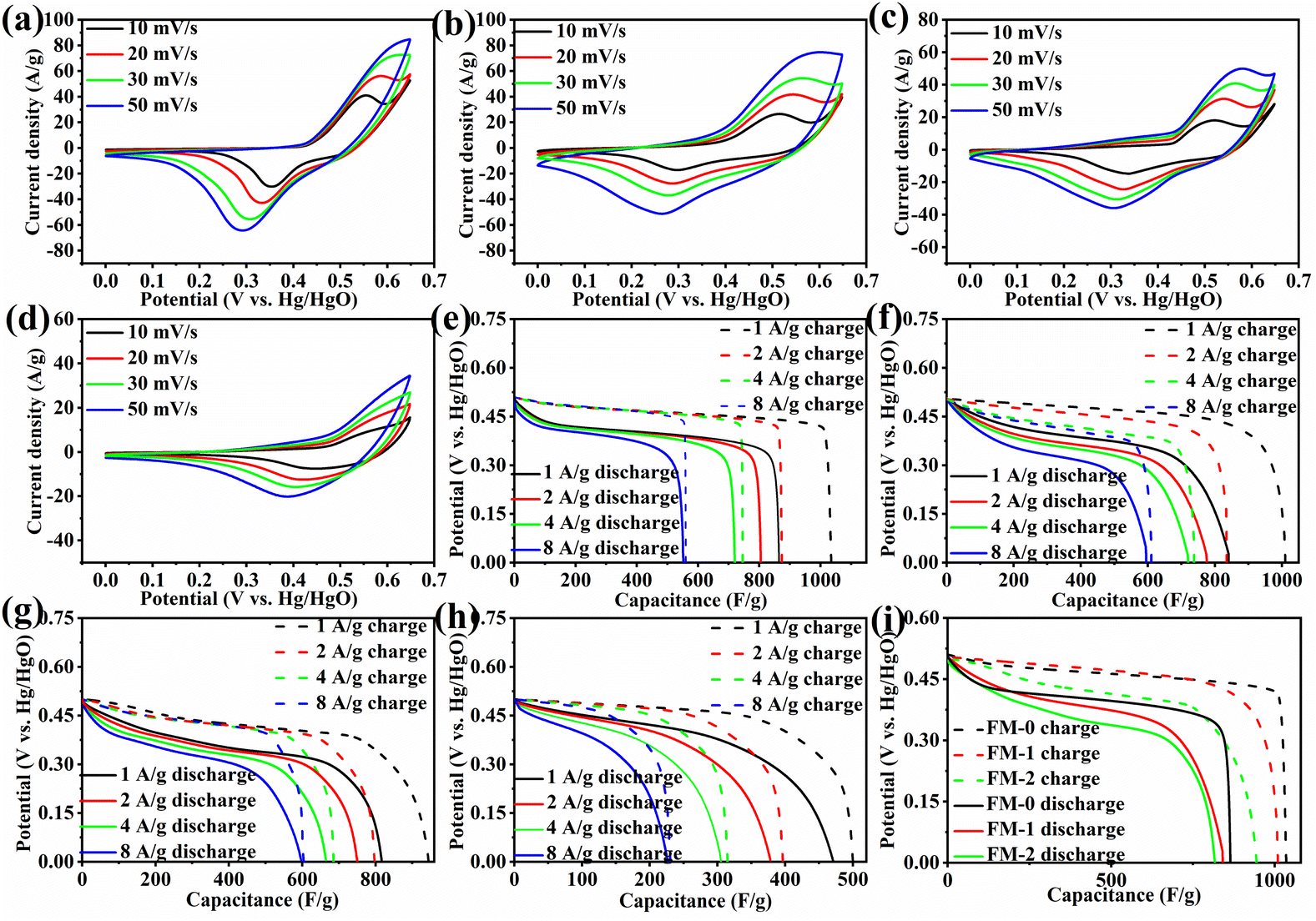 | ||
| Fig. 3 (a–d) CV contrast of the samples form FM-0 to FM-3 at 10-50 mV s−1. (e–h) GCD curves of the samples at 1–8 A g−1. (i) Charge/discharge curve at 1 A g−1. | ||
| Sample | Thickness (mm) | Resistivity (m Ω cm) | Conductivity (s cm−1) |
|---|---|---|---|
| FM-0 | 0.351 | 0.4 | 2500 |
| FM-2 | 0.326 | 0.2 | 5000 |
| FM-3 | 0.372 | 0.3 | 3333 |
Fig. 4(a) shows the change in specific capacitance for all samples at a current density of 1 A g−1 for 1000 cycles. As can be seen from the figure, the cycling stability of sample FM-0 is very poor, decaying to 80% of the initial specific capacitance after 200 cycles and only about 157 F g−1 after 1000 cycles. The poor cycling stability is due to the poor reversibility of the reaction of the Fe2O3 material as a binary metal oxide on the one hand, and the high volume rate change resulting in the performance degradation. The increase of MgFe2O4 content, the cycling stability gradually increases, and for the FM-1 sample, it can maintain 80% specific capacitance after 500 cycles, while the FM-2 sample can still have 81.25% specific capacitance retention after 1000 cycles. This indicates that the composite of MgFe2O4 materials can provide an improvement in the cycling stability of Fe2O3 sheet electrodes. For the FM-3 sample, again the cycling stability is poor, reaching 80% of the initial specific capacitance after approximately 250 cycles and only 46.2% of the initial specific capacitance after 1000 cycles. The results for cyclic stability also support the conclusion that the two materials have a synergistic effect. Fig. 4(b) shows the impedance plots before and after the FM-0 and FM-2 cycles. The initial impedance of FM-0 and FM-2 are 1.2 Ω and 0.7 Ω respectively, with FM-2 having a slightly lower impedance than FM-0. After cycling, both impedances increase, with FM-0 increasing to 2.2 Ω and FM-2 increasing to 1.5 Ω. The increase in impedance may be due to a reduction in material activity, and the lower impedance of FM-2 also improves its cycling stability.
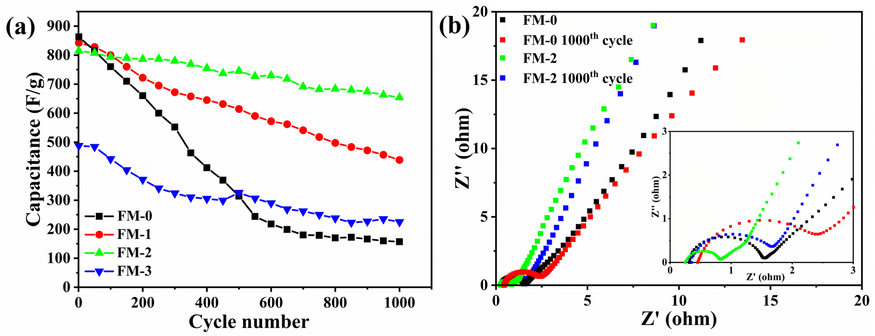 | ||
| Fig. 4 (a) Cycling stability performance of FM-0 to FM-3 at 1 A g−1 (b) electrochemical impedance of FM-0 and FM-2 samples before and after cycling. | ||
3.3 Morphological analysis
Morphological analysis of the loaded material of FM-0 and FM-2 samples was done to explore the reason of the improved cycling stability. Fig. 5(a–b) correspond to Scanning Electron Microscope (SEM) images of FM-0 and their high magnification images, respectively. As can be seen from the Fig. 5(a), it can be clearly seen that a high density of Fe2O3 flakes was grown on the nickel foam. The nanosheets are stacked in layers and form a certain heigh. Fig. 5(b) shows a high magnification SEM image of the FM-0, through which the morphology of each nanosheet can be observed. By selecting a number of nanosheets and using the labelling software to perform calculations, the average length of the nanosheets can be obtained to be about 1 μm and the thickness to be about 42 nm. These nanosheets expose more contact area, which also results in a higher initial specific capacitance. The Fe2O3 nanosheets cross each other and this layered porous structure facilitates ion storage and reducing ion diffusion distances.41,42 However, the size of each nanosheet is still large and the smaller volume means a larger specific surface area and is less affected by volume changes in the redox reaction.43–45 On the other hand, as shown in Fig. 3(a), a high degree of stacking of Fe2O3 nanosheets on nickel foam. This buildup may lead to lower material utilisation and also to material shedding during charging and discharging. Furthermore, although nickel foam provides a fast electron transport channel, the highly stacked nanosheets away from the nickel foam represent poor electron conduction, making Fe2O3 perform poorly in cycling stability tests.46,47 Fig. 5(c) shows an SEM image of FM-0 after 1000 cycles. | ||
| Fig. 5 (a, b) FESEM images of FM-0 sample. (c) SEM image of FM-0 after 1000 cycles. (d and e) FESEM images of FM-2 sample. (f) SEM image of FM-2 after 1000 cycles. | ||
It can be seen that some of the Fe2O3 nanosheets are fractured or broken after the charge/discharge cycle, and some nanosheets have chipped edges where they should be smooth. These breakages may occur because the larger volumes of Fe2O3 nanosheets are subject to large volume changes during cycling, resulting in more significant material loss. This loss largely affects the cycling stability of the materials. Fig. 5(d–e) shows the TEM image and high magnification TEM image of the FM-2 nanosheet. As seen in Fig. 5(c), the Fe2O3 nanosheet size is significantly reduced in the Fe2O3/MgFe2O4 sheet electrode compared to Fe2O3, which makes Fe2O3 less affected by volume changes and its longitudinal stacking phenomenon is significantly improved, as evidenced by the thinner electrode sheet thickness. The enhancing the cycling stability of the sheet electrode to a certain extent. Fig. 5(e) show that Fe2O3 nanosheets are much smaller in size, ranging from 100–300 nm in length, with an average thickness of about 15 nm, and nanoparticles of about 32 nm in diameter growing in the interlaced interlayer of the nanosheets. There is also a synergistic effect between the Fe2O3 nanosheet and the nanoparticles, increasing the number of electrochemically active sites for charge storage, which also affects their cycling stability.48,49 Fig. 5(f) shows the SEM image of FM-2 after 1000 cycles, from which it can be seen that there is no significant structural change in the nanosheet. Only the edges of some nanosheets are slightly damaged. The maintenance of the morphology of the material after cycling is also the guarantee of the stability.
The FM-2 was ultrasonically cleaned to obtain a partially Fe2O3/MgFe2O4 loaded material. The active material was characterised by TEM as shown in Fig. 6(a–c). This figure provides a better visualisation of the Fe2O3 nanosheets and MgFe2O4 nanoparticles in a composite state. Two areas were selected for lattice stripe characterisation by HETEM, as shown in Fig. 6(b and c). Fig. 6(b) corresponds to the dark lamellar nano region with a lattice spacing of 2.21 nm, corresponding to the (1 1 3) crystal plane of Fe2O3. Fig. 6(c) corresponds to the light coloured region of the diagram with a lattice spacing of 2.09 nm, corresponding to the (4 0 0) crystal plane of MgFe2O4. Further indications suggest that the light coloured spherical material is MgFe2O4, also indicating that the sample retains its original crystal structure. Fig. 6(d and e) show the energy dispersive spectroscopy (EDS) images for the elements Mg and Fe respectively, and Fig. 6(f) shows the EDS layered images for the element Mg, Fe and O. As can be seen from the figures, the elements Mg and Fe are well distributed on the nickel foam substrate and the growth is relatively complete.
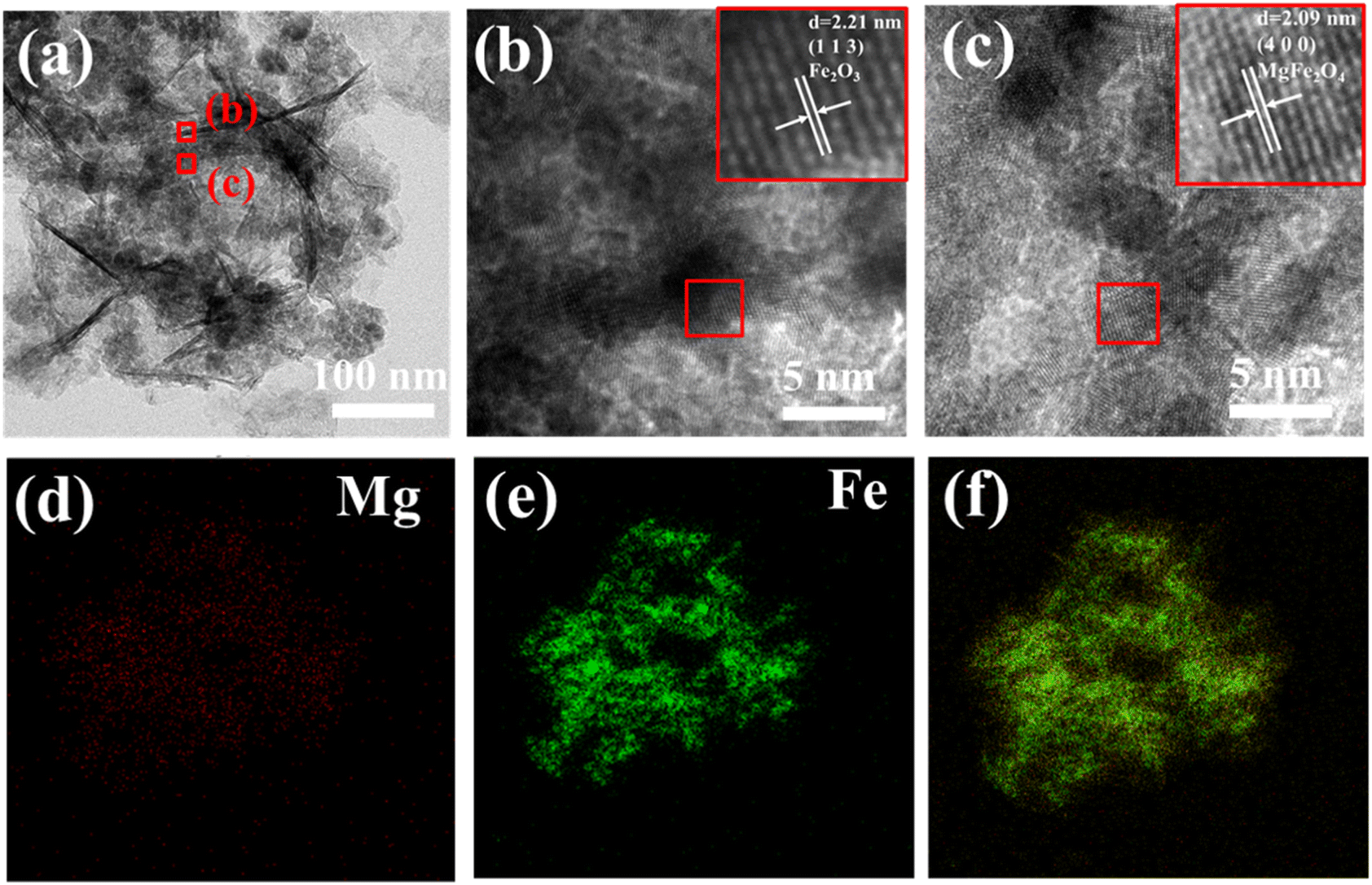 | ||
| Fig. 6 (a–c) TEM (a) and HETEM (b and c) of FM-2. (d–f) EDS (d) Mg (e) Fe (f) layered images. | ||
Fig. 7 shows the 1s spectra of O and 2p spectra of Fe for samples FM-0 and FM-2 before and after cycling. Fig. 7(a) shows the O 1s spectra of FM-0 and FM-2 before and after cycling. All curves can be fitted to three components corresponding to lattice oxygen (OI), chemisorbed oxygen (OII) and physisorbed oxygen (OIII). Since OII is associated with uncoordinated electrons in the oxygen vacancy, its content is somewhat representative of the material activity.50 From Fig. 7(b) it can be seen that both FM-0 and FM-2 decrease in OII percentage before and after cycling, FM-0 has the highest initial OII percentage but drops to the lowest percentage after cycling, which can be inferred to be a greater degree of material deactivation. Fig. 7(c–f) shows the Fe 2p spectra of FM-0 and FM-2 before and after cycling. As can be seen from the figures, Fe 2p has two distinctive characteristic peaks at 710.8 eV and 724.4 eV that can correspond to the peaks of Fe 2p3/2 and Fe 2p1/2. The position of this peak is in agreement with previous reports.51 The peaks for Fe2+ and Fe3+ can be obtained by fitting, and the ratio of the two valence atoms can be obtained by comparing the peak areas. The Fe2+/Fe3+ atomic ratio was calculated to be 1.35 before cycling tests and decreased to 0.39 after cycling. for sample FM-2, the Fe2+/Fe3+ atomic ratio was 1.1 before cycling and remained at 0.73 after cycling. more Fe2+ content means more active sites,52 so it can be assumed that sample FM-2 retained more active sites after cycling, whereas the loss of active sites in the FM-0 sample could be due to an irreversible reaction taking place.
 | ||
| Fig. 7 (a) XPS spectra of O 1s (b) O1, O2 and O3 content before and after FM-0 and FM-2 charge/discharge cycles (c–f) XPS Fe 2p spectrum of FM-0 (c) and FM-0 after charge/discharge cycles (d) and FM-2 (e) and FM-2 after charge/discharge cycles (f). | ||
The specific surface area and pore size are equally telling for the increased reversibility of the reaction and the synergistic effect of the electrode sheet loading materials. We scraped the active materials of FM-0 and FM-2 and performed N2 isothermal adsorption/desorption experiments to calculate the specific surface area and pore size of the materials, as shown in Fig. 8. Fig. 8(a, c) shows the N2 adsorption/desorption isotherms of the FM-0 and FM-2 samples, respectively. As can be seen from the graphs, the adsorption curves for both materials are type IV curves in the Brunauer–Deming–Deming–Teller (BDDT) classification, with the adsorption curves in the low pressure region biased towards the Y-axis, indicating the presence of more micropores and stronger interactions with the curves in the medium pressure region indicate that sample buildup has produced pore channels in the mesoporous range. The hysteresis lines in the high pressure region are all of the H3 type, indicating that the stacked pores are of the slit type, which is also consistent with the stacking style of the nanosheets in the SEM characterisation. Sample FM-0 was loaded with Fe2O3 nanosheets with a specific surface area of 148.8 m2 g−1 and sample FM-2 was loaded with Fe2O3 nanosheets compounded with MgFe2O4 nanoparticles with an increased specific surface area of 180.4 m2 g−1. It is evident from the SEM characterisation that the addition of MgFe2O4 material reduces the size of the Fe2O3 material and the smaller nanosize leads to a larger The larger specific surface area of the FM-2 loaded material provides more active sites and better activity retention during the charging and discharging process. Fig. 8(b, d) shows the pore size distribution curves of the FM-0 and FM-2 sample loading materials, respectively. The pore size of the FM-0 loading material was mainly in the range of 1.81–93.9 nm with an average pore size of 10.2 nm. The pore size of the FM-2 loading material was mainly in the range of 1.85 nm-116.0 nm with an average pore size of 11.7 nm. The larger pore size in the mesopore promotes rapid mass transfer and also buffers the volume change of the electrode, providing high cycling performance.
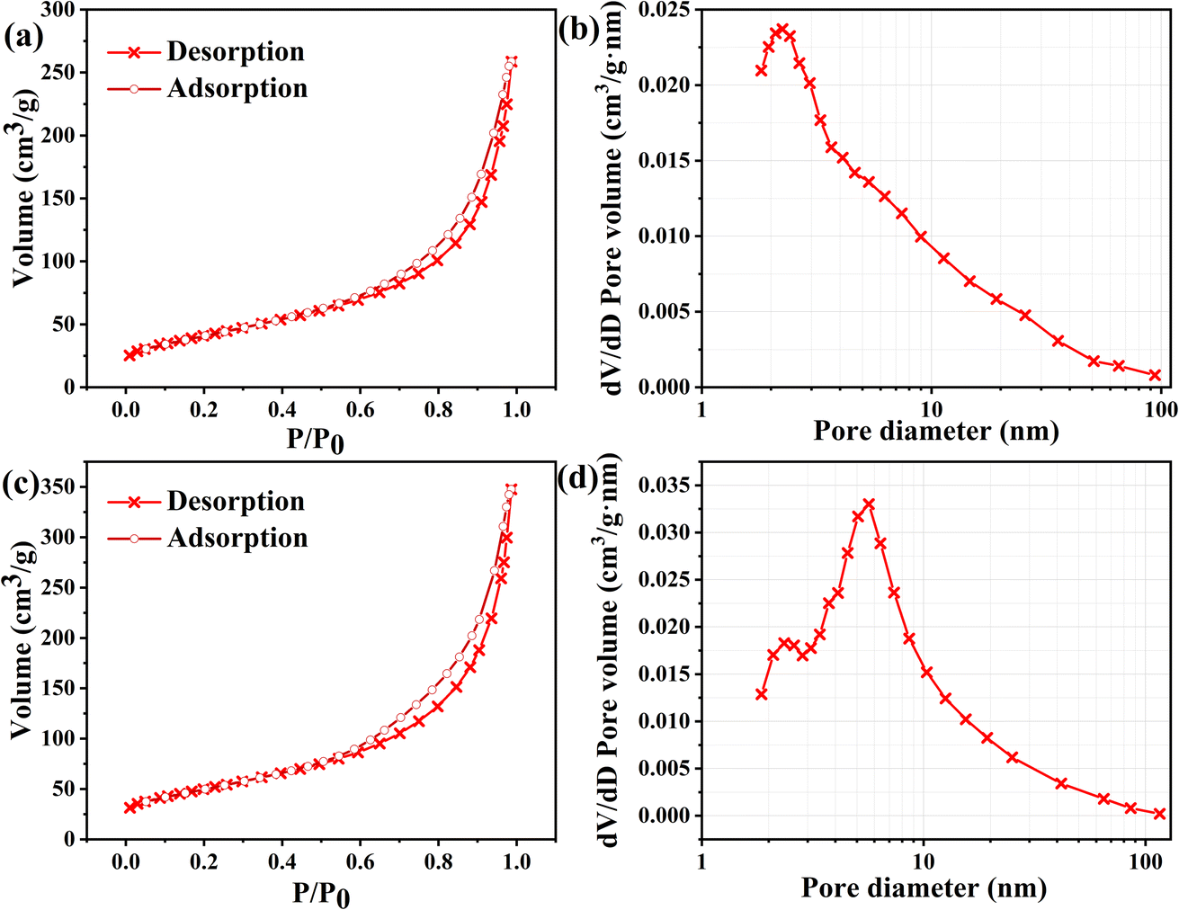 | ||
| Fig. 8 (a, c) N2 adsorption/desorption isotherms of the FM-0 and FM-2 loaded materials. (b, d) Pore size distribution curves of the FM-0 and FM-2 loaded materials. | ||
Through the above characterisation and testing, we have analysed the reasons for the enhanced cycling stability of the MgFe2O4 material. Firstly, electrochemical tests show that with the compounding of the MgFe2O4 material, the sheet electrode multiplicity performance improves and the occurrence of irreversible reactions decreases. Combined with the comparison between the samples, it can be found that the compounding of the two materials produces a synergistic effect and can possess better performance than the two materials respectively. The material morphology tests show that the MgFe2O4 material grows between the Fe2O3 nanosheets, controlling the size of the nanosheets and reducing the damage and loss of active material during the charging and discharging process. It also reduces the longitudinal accumulation of nanosheets, thus improving the cycling stability of the sheet electrode. Combining the Fe2+/Fe3+ ratios obtained from XPS tests before and after cycling, it can be seen that the Fe2O3/MgFe2O4 composites have a higher Fe2+ retention after cycling, giving them a higher specific capacitance retention due to the reaction reversibility becoming better. Calculations of specific surface area and pore size similarly demonstrate that the composite possesses better stability.
We have compiled literature on Fe2O3-related materials for supercapacitor electrode sheets, as shown in Table 3, listing the specific capacitance, number of cycles and specific capacitance retention after cycling of electrode sheets in other literature. Compared with other literature, the present work can have a high specific capacitance and at the same time can have a relatively satisfactory cycle stability, which indicates that the Fe2O3/MgFe2O4 material synthesized in the present work is competitive for use in supercapacitor electrode sheets and the material has some application value.
| Electrode materials | Electrolyte | Specific capacitance | Cycle number | Retention rate | Reference |
|---|---|---|---|---|---|
| Fe2O3 | 0.5 M Na2SO3 | 127 F g−1 | 1000 | 80% | 53 |
| Fe2O3/N-rGO | 1 M KOH | 618 F g−1 | 5000 | 56.7% | 54 |
| Mn3O4–Fe2O3/Fe3O4@rGO | 1 M KOH | 590.7 F g−1 | 1000 | 64.5% | 55 |
| Fe2O3 | 1 M KOH | 249 F g−1 | 2000 | 93.6% | 56 |
| Fe2O3/rGO | 1 M Na2SO4 | 240 F g−1 | 1000 | 75% | 57 |
| Fe2O3/MgFe2O4 | 1 M KOH | 815 F g−1 | 1000 | 81.3% | This work |
4. Conclusions
In this paper, we compounded Fe2O3 nanosheets with MgFe2O4 nanoparticles by a simple hydrothermal method and grew them on nickel foam to produce a binder-free sheet electrode. The flake electrodes have better cycling stability compared to Fe2O3 flake electrodes and MgFe2O4 flake electrodes. We have analysed the reasons for the improved cycling stability through electrochemical tests, material morphological characterisation and physical characterisation, and have drawn the following conclusions.(1) With the compounding of MgFe2O4 materials, the Fe2O3/MgFe2O4 sheet electrode has better reversibility during charging and discharging and can maintain a higher Fe2+ ratio after cycling. This is due to its smaller electrochemical impedance, more active sites due to higher specific surface area and larger pore size.
(2) The composite of MgFe2O4 nanoparticles results in smaller Fe2O3 nanosheets with less longitudinal build-up on nickel foam. The smaller size results in less structural damage of the Fe2O3 nanosheets after charge/discharge cycles. The less stacking allows for better electrical conductivity, further slowing down the effect on the structure. This results in a smaller loss of specific capacitance of the sheet electrode.
Conflicts of interest
There are no conflicts to declare.Acknowledgements
This research was supported by 111 Project (B17034) and Open project of Hubei Key Laboratory of Power System Design and Test for Electrical Vehicle granted No. 14.References
- S. Koohi-Fayegh and M. A. Rosen, J. Energy Storage, 2020, 27, 101047 CrossRef.
- A. G. Olabi, et al., Energy, 2021, 214, 118987 CrossRef CAS.
- A. L. S. Ahmed Zayed, K. Sopian and A. Al-Hinai, Energy Rep., 2020, 6, 288–306 Search PubMed.
- K. Sharma, A. Arora and S. K. Tripathi, J. Energy Storage, 2019, 21, 801–825 CrossRef.
- P. Forouzandeh, V. Kumaravel and S. C. Pillai, Catalysts, 2020, 10, 969 CrossRef CAS.
- Y. Wang, et al., J. Energy Storage, 2021, 42, 103053 CrossRef.
- Y. Shao, et al., Chem. Rev., 2018, 118, 9233–9280 CrossRef CAS PubMed.
- J. Chen and P. S. Lee, Adv. Energy Mater., 2021, 11, 2003311 CrossRef CAS.
- S. Y. Attia, et al., Rev. Inorg. Chem., 2022, 42, 53–88 CrossRef CAS.
- C. Schütter, S. Pohlmann and A. Balducci, Adv. Energy Mater., 2019, 9, 1900334 CrossRef.
- S. Fleischmann, et al., Chem. Rev., 2020, 120, 6738–6782 CrossRef CAS PubMed.
- Y. Wang, et al., J. Mater. Sci., 2021, 56, 173–200 CrossRef CAS.
- S. Najib and E. Erdem, Nanoscale Adv., 2019, 1, 2817–2827 RSC.
- Z. Bi, et al., J. Mater. Chem. A, 2019, 7, 16028–16045 RSC.
- C. Schütter, S. Pohlmann and A. Balducci, Adv. Energy Mater., 2019, 9, 1900334 CrossRef.
- A. G. Olabi, et al., Renewable Sustainable Energy Rev., 2021, 135, 110026 CrossRef CAS.
- H. Liu, X. Huan, S. Wang, H. K. Liu and L. Li, Energy Storage Mater., 2020, 28, 122–145 CrossRef.
- Y. Wang, Z. Du, J. Xiao, W. Cen and S. Yuan, Electrochim. Acta, 2021, 386, 138486 CrossRef CAS.
- D. Nandi, V. B. Mohan and A. K. Bhowmick, J. Mater. Sci., 2020, 55, 6375–6400 CrossRef CAS.
- H. Liu, et al., Energy Storage Mater., 2020, 28, 122–145 CrossRef.
- S. Yadav and A. Sharma, J. Energy Storage, 2021, 44, 103295 CrossRef.
- S. Korkmaz and İ. Afşin Kariper, J. Energy Storage, 2020, 27, 101038 CrossRef.
- Y. Wang, et al., Electrochim. Acta, 2021, 386, 138486 CrossRef CAS.
- Y. Wang, et al., ACS Appl. Mater. Interfaces, 2021, 13, 45670–45678 CrossRef CAS.
- B. Liu, et al., Adv. Funct. Mater., 2020, 30, 1909546 CrossRef CAS.
- S. J. Uke, P. M. Satish, R. B. Devidas, K. Yogesh and N. C. Gajanan, Mater. Sci. Energy Technol., 2020, 3, 446–455 CAS.
- L. Phor, S. Chahal and V. Kumar, J. Adv. Ceram., 2020, 9, 576–587 CrossRef CAS.
- A. Manohar, et al., J. Alloys Compd., 2022, 907, 164566 CrossRef CAS.
- Y. Yin, W. Liu, N. Huo and S. Yang, Chem. Eng. J., 2017, 307, 999–1007 CrossRef CAS.
- A. Syed, A. M. Elgorban, A. H. Bahkali and N. S. S. Zaghloul, Colloid Interface Sci. Commun., 2021, 44, 100467 CrossRef CAS.
- X. Yin, et al., Bull. Mater. Sci., 2021, 44, 1–7 CrossRef.
- Xu Chen, et al., RSC Adv., 2021, 11, 25170–25178 RSC.
- S. Dai, et al., J. Power Sources, 2021, 482, 228915 CrossRef CAS.
- A. Gupta, et al., ACS Appl. Energy Mater., 2020, 3, 6434–6446 CrossRef CAS.
- K. Narthana, G. Durai, P. Kuppusami and J. Theerthagiri, Int. J. Energy Res., 2021, 45, 9983–9998 CrossRef CAS.
- A. Stott and O. T. Mehmet, Energy Environ. Mater., 2020, 3, 389–397 CrossRef CAS.
- P. Ukkakimapan, et al., Diamond Relat. Mater., 2020, 107, 107906 CrossRef CAS.
- Z. Shi, et al., J. Mater. Sci. Technol., 2022, 99, 260–269 CrossRef.
- Y. Huang, et al., Nanoscale, 2018, 10.29, 14171–14181 RSC.
- Y.-Y. Xie, et al., Electrochim. Acta, 2021, 390, 138772 CrossRef CAS.
- D. Wu, et al., Chem. Eng. J., 2022, 137262 CrossRef CAS.
- L. Zheng, et al., Nanoscale, 2020, 12, 13811–13821 RSC.
- S. G. Sayyed, et al., ES Energy Environ., 2019, 3, 25–44 Search PubMed.
- S. Saha, et al., J. Energy Storage, 2018, 17, 181–202 CrossRef.
- H. Liu, et al., Energy Storage Mater., 2020, 28, 122–145 CrossRef.
- J. Liu, et al., Chem. Eng. J., 2022, 447, 137562 CrossRef CAS.
- W.-L. Hong and Lu-Y. Lin, J. Power Sources, 2019, 435, 226797 CrossRef CAS.
- N. R. Reddy, et al., J. Energy Storage, 2021, 43, 103302 CrossRef.
- V. S. Kumbhar, W. Lee and K. Lee, Ceram. Int., 2020, 46, 22837–22845 CrossRef CAS.
- Y. Wang, et al., J. Mater. Sci. Technol., 2023, 134, 142–150 CrossRef.
- Y. Wang, et al., Nanoscale Adv., 2020, 2, 2018–2024 RSC.
- G. Guo, et al., ACS Appl. Energy Mater., 2019, 3, 300–308 CrossRef.
- S. Shivakumara, T. Rao Penki and N. Munichandraiah, ECS Electrochem. Lett., 2013, 2, A60 CrossRef CAS.
- Z. Ma, et al., J. Phys. Chem. C, 2014, 118, 17231–17239 CrossRef CAS.
- R. Kumar, et al., Diamond Relat. Mater., 2020, 101, 107622 CrossRef CAS.
- X. Zheng, et al., J. Colloid Interface Sci., 2016, 466, 291–296 CrossRef CAS PubMed.
- M. Aadil, et al., J. Alloys Compd., 2016, 689, 648–654 CrossRef CAS.
| This journal is © The Royal Society of Chemistry 2023 |