 Open Access Article
Influence of sliding orientation on tribological properties of hybrid PTFE/Kevlar fabric composites
Yahong Xueab,
Xinbo Taoab,
Dongzhuang Kangab and
Shicheng Yan *ab
*ab
aTianjin Key Laboratory for Advanced Mechatronic System Design and Intelligent Control, School of Mechanical Engineering, Tianjin University of Technology, Tianjin 300384, China. E-mail: scyan0221@163.com
bNational Demonstration Center for Experimental Mechanical and Electrical Engineering Education, Tianjin University of Technology, Tianjin 300384, China
First published on 30th January 2023
Abstract
A fabric liner is an ideal self-lubricating material that has been widely used in self-lubricating spherical plain bearings. To investigate the influence of sliding orientation on the tribological properties of fabric liners, samples were prepared for different fiber orientations relative to the sliding direction and wear tests were conducted under normal loads of 25 N to 200 N. Composite-90° (sliding along Kevlar fibers) shows the best friction and wear properties under loads of 50 N and 100 N, while composite-0° (sliding along PTFE fibers) exhibits the best tribological properties when the load increases to 200 N. Due to the formation of a PTFE transfer film, the friction coefficient even decreases during the stable wear stage. Although the dry sliding condition is controlled by a transfer film formed on the friction interface, the contact geometry generated by the interlacing fibers as well as sliding direction continue to dominate the tribological properties under a light load. The combination of a suitable heavy load and sliding along the PTFE fiber is conducive to the formation of a stable and continuous transfer film of debris. Accordingly, the lowest friction coefficient of 0.105 and the lowest wear depth of 0.056 mm are achieved for composite-0° under 200 N.
Introduction
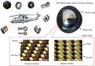
Self-lubricating spherical plain bearings are widely used in aircraft, high-speed locomotives, engineering machines, ships and submarines, medical instruments and other fields, and are key components to improve the mobility and flexibility of high-end equipment.1 By integrating low-friction PTFE fibers in the weft orientation with high-strength and superior wear-resistant Kevlar fibers in the warp orientation, hybrid PTFE/Kevlar fabric liners show excellent antifriction and wear-resistant performance, and thus they have become an ideal self-lubricating material for applications in self-lubricating spherical plain bearings.2–4 The Kevlar-rich side is the back bonded to the outer ring of the self-lubricating spherical bearing, while the PTFE-rich side is the front as the friction surface. In this configuration, the advantages of both low-friction PTFE and high-strength Kevlar are utilized (Fig. 1).5Adhesive wear of the fabric liner is one of the main forms of failure of self-lubricating spherical plain bearings. Over the years, many attempts have been made to improve the mechanical and tribological performances of the fabric liner. Fiber surface treatment, including air plasma treatment, ultrasonic treatment, and introducing polar groups on the smooth and inert fiber surface by sodium-naphthalene solution treatment, has proved to be an effective method to improve the tribological behavior of the fabric liner by enhancing the bonding strengths of the fibers and resin interfaces.6,7 Research results indicate that a suitable content of fillers, including TiO2, ZrB2, SiO2, nano-CFs, nano-SiC, WS2, MoS2, Mo2C, ZnO, CuS, and graphite, can used as internal lubricants for hybrid PTFE/Kevlar fabric liners which can effectively reduce the wear rate and enhance the load carrying capacity.8,9 Laser surface texturing (LST) could capture and store the debris, thus contributing to the accelerated formation of transfer films. By filling with PTFE and graphite as lubricants in LST microconcavities, the tribological performance of the friction pair was enhanced significantly.10,11
Additionally, the textile structures, weave density, weft density, and yarn twist of fabric liners are important factors affecting the tribological performance of fabric liners and have also been extensively studied.12–14 Results indicated a fabric liner with a satin 8/5 structure demonstrated the best antifriction and wear resistance due to the large PTFE proportions on the friction surface.15 Meanwhile, fabric liners with a twill weave were proved to possess the excellent combined properties of strength, modulus, and wear-resistance and can be favourably used under severe adhesive conditions.16 Study results obtained by Li et al.17 showed that the wear rate of hybrid Kevlar/PTFE fabric composites could be reduced by reducing the weave densities, although the friction coefficient would increase. Moreover, the practical tribological behavior of the fabric liner under extreme conditions, including heavy load conditions, water-lubricated conditions, vacuum environments or high temperature, is also a research hotspot.18,19 A higher wear rate and lower friction coefficient were observed when sliding in water.20 A double-layered transfer film was formed on the fabric liner when subjected to overloading conditions (240–330 MPa).21
The orientations of weft and warp fibers relative to the sliding direction remain almost unchanged during rotation or reciprocating swing of self-lubricating spherical plain bearings. The cutting or pasting direction of the fabric composite determines the angle between the fiber orientation and the sliding direction, affecting the tribological properties and service life of self-lubricating spherical plain bearings. Gu22 investigated the wear properties of two weaves of fabric liners along selected sliding orientations under a normal load of 8 MPa. Although the orders of friction coefficients and wear rates were given for different fabric liners and different sliding orientations, the underlying cause of this result was not clarified. Hence, for a better understanding of how the sliding orientations influence the wear properties of the hybrid PTFE/Kevlar fabric composites, a series of wear tests on the PTFE/Kevlar fabric liner were conducted by reciprocating sliding along different orientations under different loads. The mechanism for the specific effects was elaborated by analyzing the wear morphology and elemental composition. This will provide important fundamental data and theoretical guidance for manufacturing self-lubricating spherical bearings.
Experimental details
Fabrication of PTFE/Kevlar fabric composites
The hybrid PTFE/Kevlar fabric with a 1/3↗ twill woven pattern, which is widely used in type C self-lubricating spherical plain bearings, was provided by Shanghai Taiyi Bearing (Shanghai, China). The PTFE fibers were used as the weft yarn, and the Kevlar fibers were used as the warp yarn. The weave density varied between 270 and 290 threads/10 cm. The adhesive agent was 204# phenolic resin, provided by Henan Bairun New Material (Henan, China). Fig. 2 illustrates the specific procedures for specimen preparation, and it includes the preparation of a hybrid PTFE/Kevlar fabric liner and affixing the fabric liners onto stainless steel blocks for friction and wear tests. The hybrid PTFE/Kevlar fabric was first soaked in acetone at room temperature for 12 hours and then boiled in distilled water for 20 minutes. Then the hybrid PTFE/Kevlar fabric was soaked in an adhesive agent diluted by a mixture of ethanol and ethyl acetate with a blend ratio of 1![[thin space (1/6-em)]](https://www.rsc.org/images/entities/char_2009.gif) :
:![[thin space (1/6-em)]](https://www.rsc.org/images/entities/char_2009.gif) 1 for 1 h to prepare the hybrid PTFE/Kevlar fabric liner.23
1 for 1 h to prepare the hybrid PTFE/Kevlar fabric liner.23
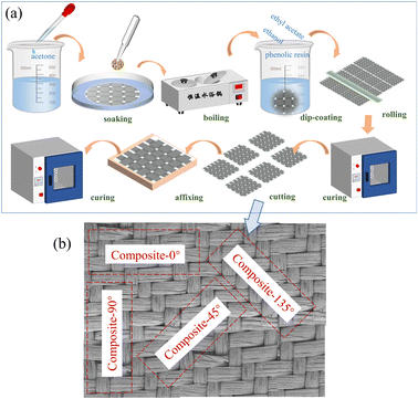 | ||
| Fig. 2 Specific procedures of specimen preparation: (a) specimen preparation procedure; (b) cutting and naming methods of different specimens. | ||
The fabric liner was cut into rectangular strips (35 mm × 25 mm) by a precision cutting device in four alignment orientations: i.e., the length direction of the strips is aligned at 0°, 45°, 90°, and 135° relative to the weft yarn direction. Several 304 stainless steel blocks (35 mm × 25 mm × 5 mm) were prepared, which were ground and polished to an average surface roughness of approximately 0.8 μm. Finally, the fabric liner strips were bonded to the stainless steel block using phenolic resin and cured in an electric blast drying oven at 180 °C for 2 h under a pressure of 0.2–0.3 MPa. The specimens were named composite-0°, composite-45°, composite-90°, and composite-135° according to the cutting orientation. The cutting and naming methods of the different fabric liners are shown in Fig. 2b.
Tribological tests
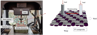
Tribological tests were conducted on a tribotester (RTEC MFT-5000, USA) with linear reciprocating motion and a pin-on-disc type contact configuration, as shown in Fig. 3. The upper specimen was a cylindrical pin (bearing steel GCr15, rigidity = 58 HRC) with a diameter of 6.35 mm, a length of 16 mm, and a chamfer of 1 mm. Before each test, the pins were polished using 600#, 1200# water sandpapers followed by cleaning ultrasonically in acetone for 15 min. The tribological tests were carried out at different loads of 25, 50, 100, and 200 N at different sliding orientations of 0, 45, 90, and 135°. The reciprocating frequency and sliding stroke length were maintained at 2 Hz and 10 mm, respectively. Each test lasted for 2 h with a total of 14![[thin space (1/6-em)]](https://www.rsc.org/images/entities/char_2009.gif) 400 reciprocating cycles and a total sliding distance of 288 m. The friction coefficient and the pin displacements in the Z direction were recorded as a function of time. Each test was repeated three times to ensure the reliability and reproducibility of the results. The mounting position of the RTEC reciprocating friction testing machine is shown in Fig. 3. Fig. 4 presents the relative movement direction between the fibers and the reciprocating pin.
400 reciprocating cycles and a total sliding distance of 288 m. The friction coefficient and the pin displacements in the Z direction were recorded as a function of time. Each test was repeated three times to ensure the reliability and reproducibility of the results. The mounting position of the RTEC reciprocating friction testing machine is shown in Fig. 3. Fig. 4 presents the relative movement direction between the fibers and the reciprocating pin.
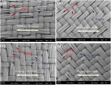 | ||
| Fig. 4 The relative movement direction between the fibers and the reciprocating pin: (a) composite-0°, (b) composite-45°, (c) composite-90° and (d) composite-135°. | ||
Experimental characterization
A high-resolution field emission scanning electron microscope (FESEM, Zeiss Sigma 300, Germany) was adopted to observe the wear morphology and microstructure of hybrid PTFE/Kevlar fabric composites and the metal pins after gold sputtering.An energy dispersive X-ray detector (EDX, Zeiss, Germany) was equipped in the SEM to determine the chemical composition and the formation of the PTFE transfer film on the surface of the pin. The tribological mechanisms were established from the chemical composition and changes in surface morphology.
Three-dimensional wear morphologies of PTFE/Kevlar fabric composites were observed with a white light interferometry 3D surface profiler (Phase Shift MicroXAM-3D, USA).
Results and discussion
Friction properties
Fig. 5 shows the variation in friction coefficients of hybrid PTFE/Kevlar fabric composites as a function of sliding time under different sliding orientations and loads. A stable increase in friction coefficient is observed during the running-in wear stage, which is caused mainly by the change in contact geometry under initial wear, i.e. from point or line contact to a more conformal contact. Then it enters a relatively stable state with a smooth sliding profile for all fabric liners, indicating a stable wear stage.24 Significant differences in friction coefficients can be noticed for fabric liners under different sliding directions. Fig. 5c and d show that stable wear is more rapidly achieved at high load intensities of 100 and 200 N.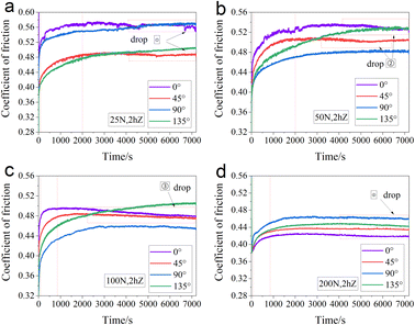 | ||
| Fig. 5 Variations in friction coefficient under different loads and sliding orientations: (a) 25 N, (b) 50 N, (c) 100 N and (d) 200 N. | ||
When the wear tests last about 2000–4000 s, a small decrease in the friction coefficient can be observed. This phenomenon is particularly obvious for composite-0° and composite-45° (i.e., sliding along or forming a small angle with PTFE fibers) under all loads, as well as composite-90° and composite-135° (i.e., sliding along or forming a small angle with Kevlar fibers) under a heavy load of 200 N. These improved tribological properties can be attributed to the formation of a smooth PTFE transfer film during the reciprocating sliding (see EDS analysis), which is transferred to the counterpart pin, thus reducing the friction coefficient.
The average friction coefficients for hybrid PTFE/Kevlar fabric composites during the stable sliding period (calculated with the average value of the last 5700 s) are summarized in the histograms in Fig. 6, with values along different sliding directions (0°, 45°, 90° and 135°) and normal loads (25 N, 50 N, 100 N and 200 N). As the load increases, the coefficient of friction decreases. This is due to the fact that it is easier to generate a lot of heat with flatter surfaces, and easier to form transfer films under a heavy load. The decrease in the coefficient of friction with increasing load is more pronounced in the case of composite-0°.
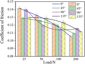 | ||
| Fig. 6 The average friction coefficients for hybrid PTFE/Kevlar fabric composites in the stable sliding period. | ||
At a low load of 25 N, the friction coefficients of composite-45° and composite-135° are almost the same and lower than those of composite-0°and composite-90°. When the load increases to 50 N and 100 N, composite-90°, i.e., sliding along the Kevlar fibers, shows the lowest friction coefficient. When the load increases to 200 N, the minimum friction coefficient is observed from composite-0°, i.e., sliding along the PTFE fibers. Under this load condition, the order of friction coefficients for different sliding directions follows the order composite-0° < composite-45° < composite-135° < composite-90°.
The initial contact geometry generated by the interlacing fibers and the PTFE transfer film formed on the surface of the pin are two aspects that play important roles in affecting friction behavior. Under a light load, the friction coefficient is closely dependent on the initial contact geometry on the friction surface, mechanical and tribological properties of fibers, as well as the angle between sliding direction and fiber direction. As the load increases, the contact surface is quickly smoothed. Due to the reduced effects of initial contact geometry, the formation of a smooth PTFE transfer film plays a dominant role, and then the difference in the friction coefficients between different sliding orientations is reduced. The detailed mechanism will be discussed later in association with the surface morphology combined with SEM-EDS analysis.
Wear depth
A displacement sensor records the Z-axis displacement at the wear interface as a function of sliding time with different sliding orientations and loads. The results are shown in Fig. 7. Due to the wearing down of the friction surface and the elastic–plastic deformation of the material under a load, a sharp drop in Z displacement occurred at the initiation of wear. After entering the stable wear period, the variation in Z displacement represents the evolution of the wear depth of the fabric composite. Compared with friction coefficients in Fig. 6, a similar influence of the sliding direction on the wear depth is observed. The sliding instability is obvious, as sharp peaks in the wear depth curve can be seen for composite-0° (i.e., sliding along PTFE fibers) when the load is less than 200 N. Correspondingly, it shows the highest wear depth compared with other sliding directions. Composite-90° shows the lowest wear depth when the load is between 50 N and 100 N, which follows the same pattern as previously discussed friction coefficients. When the load increases to 200 N, the wear depth curves show a smoother sliding profile and sliding stability, and composite-0° possesses the best wear resistance.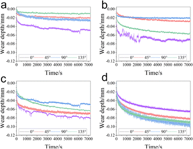 | ||
| Fig. 7 The Z-axis displacement as a function of sliding time: (a) 25 N, (b) 50 N, (c) 100 N and (d) 200 N. | ||
One set of wear depths after the tests with a normal load of 200 N is presented in Fig. 8. The wear depth for composite-0°, composite-45°, composite-90°, and composite-135° are 0.056, 0.072, 0.078 and 0.073 mm, respectively, which are slightly less than the Z displacement under the same wear conditions in Fig. 7d (0.064, 0.086, 0.083 and 0.081 mm). The reason is that, apart from the material loss in the thickness due to wear, the elastic and plastic deformation of the composite also contributes significantly to the change in the Z displacement. Under a load of 200 N, a fabric liner with sliding along PTFE fibers (composite-0°) shows significantly better wear resistance in parallel with the friction properties compared with other sliding directions, although it shows worse friction and wear properties under loads of 25, 50, and 100 N.
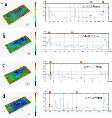 | ||
| Fig. 8 Wear depth after wear tests of the composites under a load of 200 N: (a) composite-0°, (b) composite-45°, (c) composite-90° and (d) composite-135°. | ||
Surface morphology analysis
The worn surface morphologies of the hybrid PTFE/Kevlar fabric composites sliding against pins under a load of 50 N are illustrated in Fig. 9. We can see that the wear locations are essentially the same regardless of the sliding direction, mainly dispersed at the interlacing points of warp yarns. Besides, due to interlacing between warp and weft yarns, twisting of the PTFE fibers occurs, resulting in slight abrasion at two humps of PTFE yarns on each floating length. Due to the scattered wear locations, it is not easy to form uniform transfer films. The wear of the fabric liner in different sliding directions at lower loads is mainly influenced by the surface geometry of the fabric. The sliding resistance parallel to the fiber orientation is less than that perpendicular to the fiber orientation, resulting in composite-90° possessing the lowest friction coefficient and wear rate. | ||
| Fig. 9 Worn morphologies of the fabric composites under a load of 50 N: (a) composite-0°, (b) composite-135° and (c) composite-90°. | ||
Fig. 10 shows the worn surface morphologies of the composites under a load of 200 N. It can be seen that the damage is no longer localized to the interlacing regions, but rather a widespread severe degradation of fibers is observed. During the rubbing process, the upper specimen contacts the surface of the PTFE/Kevlar fabric composite to generate a relative motion while giving a forward shear force to the fibers, squeezing them to slide forward. The abrasion performance is influenced by the sliding direction relative to the direction of the fibers.
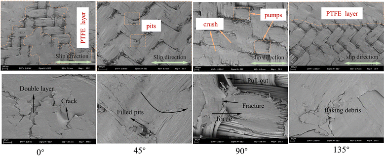 | ||
| Fig. 10 SEM morphologies of the fabric composites at different sliding directions under a load of 200 N. | ||
For composite-0°, since the sliding direction follows the PTFE fiber orientation, its damage is mainly due to the thinning wear of the PTFE fibers. The surface topography of PTFE fibers appears smooth with no severe fiber pulling, cracking, or fiber breakage. Due to adhesive wear, shear force squeezes the PTFE fibers to slide forward, causing a small portion of debris being pushed and trapped into the inter-fiber space, while a significant portion of abrasive debris will cover the adjacent Kevlar fibers along the sliding direction. This is favorable for producing a stable and uniform lubricating layer of PTFE to protect the Kevlar fibers from severe abrasion. The surface topography of composite-0° is smooth and covered by a thin PTFE self-lubricating layer, providing the lowest friction coefficient as well as wear rate among all sliding directions under heavy load conditions. At the intersection between latitude and longitude, cracks and delamination were observed on the PTFE self-lubricating layers, indicating that a new layer may occur under heavy load conditions to form a double lubricating layer.21
Similar wear results can be seen from composite-45° and composite-135°. Fibers at the interlacing regions are preferentially squashed and worn down due to stress concentration. Because of the lower shear resistance, the PTFE fibers in the middle of straight thread regions are squeezed out to form flaking debris. Nevertheless, the exfoliated fibers slip to fill the pits between the interlacing junctions, which play a positive role in forming a connected PTFE self-lubricating layer.
For composite-90°, the sliding direction is consistent with the orientation of the Kevlar fibers. The composite gradually wears along the longitudinal axis by thinning of the Kevlar fibers. Kevlar fibers provide good wear resistance because of their high load capacity and scratch resistance, resulting in smooth wear surfaces with little fiber breakage or pull-out. PTFE fibers are subjected to shear in the direction perpendicular to the fiber orientation. Thus, severe compressive and shear forces squeeze the fibers forward with slipping. Due to poor shear resistance, this wear caused extensive fiber fibrillation, fracture, and fiber pull-out on one side of PTFE yarns near the adjacent interlacing point of the warp yarn. The PTFE fibers are squashed and crushed in multiple places. Hence, the formation of a stable and continuous transfer film is not favorable in this case, which explains the highest coefficient of friction and wear depth for composite-90°.
SEM-EDS analysis of PTFE transfer film
The formation of a transfer film on the counterpart pin is determined by the interaction of wear abrasive debris on the friction surface under the coupling effect of high temperature and shear force. To verify the formation of a transfer film under a load of 200 N, SEM-EDS analysis on the metal pin after sliding tests under different sliding directions is shown in Fig. 11.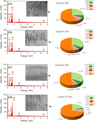 | ||
| Fig. 11 SEM-EDS analysis of the counterpart pin under different sliding directions: (a) composite-0°, (b) composite-45°, (c) composite-90° and (d) composite-135°. | ||
The chemical elements of the worn metal pin are mainly composed of C, O, F, Si, Cr, and Fe. The detected F element in EDS analysis and black bands parallel to the sliding direction in the SEM image proves that PTFE is transferred to the pin to form a transfer film during abrasion. Softening and lowering the surface energy of PTFE under thermal and shear deformation promote the formation of the PTFE transfer films. A high load makes it easy to transfer the soft material to the friction counterpart and reduce the friction coefficient. It agrees with the friction measurement results of a lower friction coefficient and smooth sliding properties under a heavy load of 200 N. SEM images indicate that PTFE transfer film deposited on the counterpart pin with striations distributed oriented along the sliding direction, and they are still fragmented rather than forming a large continuous sheet after the wear tests. F content changes with different sliding directions, with a maximum F content of 7.96% deposited on the metal pin detected in the counterpart pin of composite-0° combined with the most homogeneous and full covering of transfer film, in parallel with the minimum friction coefficients among all directions. Micro-cutting is detected on the metal counter surface, demonstrating that abrasive wear accrued under the study conditions in addition to the adhesive wear.
Conclusions
The tribological properties of a hybrid PTFE/Kevlar fabric composite with different sliding directions and load intensities were studied using pin-on-disc tests. Based on the experimental results, the main conclusions can be drawn as follows:The load magnitude and sliding directions comprehensively affect the friction coefficient and wear rate. A suitable high load makes it easy to transfer the soft material to the friction counterpart and form a transfer film, resulting in friction coefficients decreasing with an increase in load for composite-0°, composite-45° and composite-135°. Composite-90° shows the lowest wear depth when the loads are 50 and 100 N, which follows the same pattern as friction coefficients. When the load increases to 200 N, the sliding stability of the composites is improved and composite-0° possesses the best friction property as well as wear resistance.
Under a light load, the friction coefficient is closely dependent on the initial contact geometry on the friction surface, mechanical and tribological properties of fibers, as well as the angle between sliding direction and fiber direction. As the load increases, the formation of a smooth PTFE transfer film plays a dominant role.
The PTFE transfer film is deposited on the counterpart pin with striations distributed oriented along the sliding direction. The smooth PTFE transfer film formed in the reciprocating sliding process leads to a decrease in friction coefficient in the stable wear stage. This improved tribological property is particularly evident when sliding along or forming a small angle with PTFE fibers, as well as under heavy loads.
The maximum F content of 7.96% deposited on the metal pin is detected in the counterpart pin of composite-0° combined with the most homogeneous and full covering of transfer film, in parallel with the minimum friction coefficients among all directions.
When sliding along the PTFE fibers under a heavy load, the shear force squeezes the PTFE fiber to slide forward, causing a small portion of debris to be pushed and trapped into the inter-fiber space, while a significant portion of abrasive debris will cover the adjacent Kevlar fibers along the sliding direction. This is conducive to the formation of a stable and continuous PTFE solid lubricating layer to protect the Kevlar fiber from severe abrasion. Accordingly, composite-0° under a heavy load of 200 N provides the lowest friction coefficient as well as wear rate among all sliding directions and load conditions.
Author contributions
Yahong Xue: funding acquisition, conceptualization, data curation and writing original draft. Xinbo Tao: review & editing. Shicheng Yan: supervision, validation, writing, review & editing.Conflicts of interest
There are no conflicts to declare.Acknowledgements
This work was financially supported by the National Natural Science Foundation of China (Grant No. 52105198) and Technical Innovation Guidance Project of Tianjin Science and Technology Bureau (Grant No. 21YDTPJC00390).References
- J. Liu, F. Lu and S. Du, et al., Friction and wear behaviors of Kevlar/polytetrafluoroethylene braided composite in oscillatory contacts, J. Mater. Eng. Perform., 2020, 29(4), 2605–2611 CrossRef CAS.
- Y. Xue, S. Yan and J. Xie, et al., Contact and tribological properties of self-lubricating ellipsoidal plain bearings, Tribol. Int., 2019, 140, 105840 CrossRef.
- W. Cui, K. Raza and Z. Zhao, et al., Role of transfer film formation on the tribological properties of polymeric composite materials and spherical plain bearing at low temperature, Tribol. Int., 2020, 152, 1–11 CrossRef.
- Y. Liu, N. Xu and Y. Wang, et al., Preparation and tribological properties of hybrid PTFE/Kevlar fabric self-lubricating composites-ScienceDirect, Surf. Coat. Technol., 2019, 361, 196–205 CrossRef CAS.
- J. Lu, M. Qiu and Y. Li, Wear models and mechanical analysis of PTFE/Kevlar fabric woven liners used in radial spherical plain bearings, Wear, 2016, 364–365, 57–72 CrossRef CAS.
- G. Ren, Z. Zhang and X. Zhu, et al., Combined effect of air-plasma treatment and lubricant filling on the dry sliding wear behavior of hybrid PTFE/Nomex fabric/phenolic composite, Compos. Sci. Technol., 2014, 100, 204–211 CrossRef CAS.
- M. Qiu, Y. Miao and Y. Li, et al., Influence of ultrasonic modified liners on the adhesive and tribological performances of self-lubricating radial spherical plain bearings, Tribol. Trans., 2016, 59(4), 655–662 CrossRef CAS.
- M. Qiu, J. Lu and Y. Li, et al., Investigation on MoS2 and graphite coatings and their effects on the tribological properties of the radial spherical plain bearings, Chin. J. Mech. Eng., 2016, 29(4), 844–852 CrossRef CAS.
- H. Li, F. Zeng and Z. Yin, et al., A study on the tribological behavior of hybrid PTFE/Kevlar fabric composites filled with nano-SiC and/or submicron-WS2 fillers, Polym. Compos., 2016, 37(7), 2218–2226 CrossRef CAS.
- X. Qi, W. Hai and D. Yu, et al., Experimental analysis of the effects of laser surface texturing on tribological properties of PTFE/Kevlar fabric composite weave structures, Tribol. Int., 2019, 135, 104–111 CrossRef CAS.
- H. Wang, X. Qi and A. Sun, et al., Wear properties of textured lubricant films filled with graphite and polytetrafluoroethylene (PTFE) via laser surface texturing (LST), Tribol. Int., 2022, 167, 107414 CrossRef CAS.
- J. Bijwe and R. Rattan, Influence of weave of carbon fabric in polyetherimide composites in various wear situations, Wear, 2007, 263(7–12), 984–991 CrossRef CAS.
- X. Qi, J. Ma and Z. Jia, et al., Effects of weft density on the friction and wear properties of self-lubricating fabric liners for journal bearings under heavy load conditions, Wear, 2014, 318(1–2), 124–129 CrossRef CAS.
- J. Ma, B. L. Fan and Y. J. Gao, et al., Effects of Kevlar29 yarn twist on tensile and tribological properties of self-lubricating fabric woven, J. Ind. Text., 2016, 46(8), 1698–1714 CrossRef.
- D. Gu, Y. Yang and X. Qi, et al., Influence of weave structures on the tribological properties of hybrid Kevlar/PTFE fabric composites, Chin. J. Mech. Eng., 2012, 25, 1044–1051 CrossRef.
- R. Rattan, J. Bijwe and M. Fahim, Influence of weave of carbon fabric on low amplitude oscillating wear performance of Polyetherimide composites, Wear, 2007, 262(5–6), 727–735 CrossRef CAS.
- H. L. Li, Z. Yin and D. Jiang, et al., Tribological behavior of hybrid PTFE/Kevlar fabric composites with different weave densities, Ind. Lubr. Tribol., 2016, 68(2), 278–286 CrossRef.
- D. Gu, C. Duan and B. Fan, et al., Tribological properties of hybrid PTFE/Kevlar fabric composite in vacuum, Tribol. Int., 2016, 103, 423–431 CrossRef CAS.
- G. Ren, Z. Zhang and X. Zhu, et al., High-temperature tribological performance of hybrid PTFE/Nomex fabric/phenolic composite, Compos. Sci. Technol., 2014, 104, 146–151 CrossRef CAS.
- L. Ying, D. Jiang and Z. Yin, The tribological properties of multilayer hybrid PTFE/Nomex fabric/phenolic resin composite with two fabric structure under water lubrication, Mater. Res. Express, 2021, 8(10), 105505–105513 CrossRef.
- H. Wang, X. Qi and W. Zhang, et al., Tribological properties of PTFE/Kevlar fabric composites under heavy loading, Tribol. Int., 2020, 151, 106507 CrossRef CAS.
- D. Gu, L. Zhang and S. Chen, et al., Reciprocating sliding wear of hybrid PTFE/Kevlar fabric composites along different orientations, RSC Adv., 2018, 8(37), 20877–20883 RSC.
- P. Li, Z. Zhang and M. Yang, et al., Synchronously improved thermal conductivity and tribological performance of self-lubricating fabric liner composites via integrated design method with copper yarn, Tribol. Int., 2021, 164, 107204 CrossRef CAS.
- D. Tan, R. Li and X. Yang, et al., Tribological behavior of PTFE/Kevlar fabric under different contact stresses, AIP Adv., 2021, 11(3), 035233 CrossRef CAS.
| This journal is © The Royal Society of Chemistry 2023 |

