
 Open Access Article
 This Open Access Article is licensed under a Creative Commons Attribution-Non Commercial 3.0 Unported Licence
Metal–organic framework derived vanadium oxide supported nanoporous carbon structure as a bifunctional electrocatalyst for potential application in metal air batteries
Rimsha Mehek a,
Naseem Iqbal*a,
Tayyaba Noorb,
Zahid Ali Ghazic and
Muhammad Umaira
a,
Naseem Iqbal*a,
Tayyaba Noorb,
Zahid Ali Ghazic and
Muhammad Umaira
aUS-Pakistan Center for Advanced Studies (USPCAS-E), National University of Sciences and Technology (NUST), H-12, Islamabad 44000, Pakistan. E-mail: naseem@uspcase.nust.edu.pk; Tel: +92 51 9085 5281
bSchool of Chemical and Materials Engineering (SCME), National University of Sciences and Technology (NUST), H-12, Islamabad 44000, Pakistan
cNational Centre of Excellence in Physical Chemistry, University of Peshawar, 25120, Pakistan
First published on 23rd December 2022
Abstract
High-efficiency, sustainable, non-precious metal-based electrocatalysts with bifunctional catalytic activity for the oxygen reduction reaction (ORR) and the oxygen evolution reaction (OER) are essential for metal–air batteries. In this research, a bifunctional electrocatalyst is developed by synthesizing a novel nanoporous vanadium oxide/carbon composite (NVC-900) through pyrolysis of a highly efficient vanadium metal–organic framework, MIL-101 (V). The fabrication process was conveniently carried out by pyrolyzing the synthesized MIL-101 (V) at 900 °C, producing vanadium oxide nanoparticles embedded in the extensively distributed pores of the carbon network. The evenly distributed nanopores substantially improve the performance of the efficient electrocatalyst for both the oxygen reduction reaction and oxygen evolution reactions (ORR/OER) by increasing surface area and facilitating access to stable catalytic active sites. The unique structure was characterized by powder X-ray diffraction (XRD) and scanning electron microscopy (SEM). For oxygen reduction reaction (ORR), the electrocatalyst established a promising limiting current density (JL) of 5.2 mA cm−2 at 1600 rpm at an onset potential of 1.18 V and a half-wave potential of 0.82 V, and for OER, a current density of 10 mA cm−2 was delivered at a potential of 1.48 V. In comparison to 10% Pt/C, the synthesized bifunctional electrocatalyst being almost equally active towards bifunctional activity, showed much better long-term cyclic stability. The one-step thermal pyrolysis strategy to synthesize the nanoporous functional material and the proposed electrocatalytic material's long-term bifunctional activity and durability make it an ideal fit for next-generation portable green metal–air batteries.
1. Introduction
In the on-going pursuit for environmentally benign and cost-effective energy conversion and storage devices, metal air batteries have garnered great attention due to their high theoretical energy density of 11![[thin space (1/6-em)]](https://www.rsc.org/images/entities/char_2009.gif) 140 W h kg−1.1–3 This energy density value is almost as high as that of gasoline. Due to which, metal air batteries have potential scope as a power source in electrical vehicles, portable electronics and aerospace devices4–6 having the tendency to perform better than lithium ion batteries.7 Among all the different types of metal air batteries, aqueous metal air batteries are the most common and the most efficient ones.8 The complete electrochemical cycle of a metal–air battery consists of the oxygen reduction reaction (ORR) and oxygen evolution reaction (OER), producing hydroxides and oxygen during the discharge and charging respectively.9 The lethargic and thus slow kinetics of both the ORR and OER processes lead to the significant stalling in both processes, resulting in high charge/discharge overpotential, low cycle efficiency, and a short cycle life.10–12 In order to improve the overall efficiency of the metal air battery system, an efficient and cost effective electrocatalyst is required which has the capacity to catalyze either both or at least the oxygen reduction reaction (ORR). Noble metal based electrocatalysts have always performed very well because of their high energy densities but only for one of the reactions.13–17 In addition to the monofunctionality, these materials come with their baggage of problems. Platinum dominates as an ORR electrocatalyst for its superior electrocatalytic activity and extraordinary stability. The problem with platinum lies with its scarcity and hence high prices. Moreover, Pt is also responsible for the in situ production of poisonous platinum oxide based bi-products which insulate the active sites.18–22 Similarly, for OER, RuO2 has proved its extraordinary performance as electrocatalyst while it's also expensive. The scarcity of the expensive reserves of both the platinum and ruthenium is an unavoidable challenge in the way of the large-scale commercial application of the noble metal electrocatalysts. Therefore, a fundamental prerequisite for improving the capability of batteries is to build a low-cost, high efficiency electrocatalysts with bifunctional activities for both the reactions.23 Therefore, developing a cost-effective, efficient, and stable non-precious metal-based bifunctional electrocatalyst for metal air batteries is highly sought-after research interest.24–27
140 W h kg−1.1–3 This energy density value is almost as high as that of gasoline. Due to which, metal air batteries have potential scope as a power source in electrical vehicles, portable electronics and aerospace devices4–6 having the tendency to perform better than lithium ion batteries.7 Among all the different types of metal air batteries, aqueous metal air batteries are the most common and the most efficient ones.8 The complete electrochemical cycle of a metal–air battery consists of the oxygen reduction reaction (ORR) and oxygen evolution reaction (OER), producing hydroxides and oxygen during the discharge and charging respectively.9 The lethargic and thus slow kinetics of both the ORR and OER processes lead to the significant stalling in both processes, resulting in high charge/discharge overpotential, low cycle efficiency, and a short cycle life.10–12 In order to improve the overall efficiency of the metal air battery system, an efficient and cost effective electrocatalyst is required which has the capacity to catalyze either both or at least the oxygen reduction reaction (ORR). Noble metal based electrocatalysts have always performed very well because of their high energy densities but only for one of the reactions.13–17 In addition to the monofunctionality, these materials come with their baggage of problems. Platinum dominates as an ORR electrocatalyst for its superior electrocatalytic activity and extraordinary stability. The problem with platinum lies with its scarcity and hence high prices. Moreover, Pt is also responsible for the in situ production of poisonous platinum oxide based bi-products which insulate the active sites.18–22 Similarly, for OER, RuO2 has proved its extraordinary performance as electrocatalyst while it's also expensive. The scarcity of the expensive reserves of both the platinum and ruthenium is an unavoidable challenge in the way of the large-scale commercial application of the noble metal electrocatalysts. Therefore, a fundamental prerequisite for improving the capability of batteries is to build a low-cost, high efficiency electrocatalysts with bifunctional activities for both the reactions.23 Therefore, developing a cost-effective, efficient, and stable non-precious metal-based bifunctional electrocatalyst for metal air batteries is highly sought-after research interest.24–27
Apart from Pt and Ru, there are a number of other non-noble transition metals which have the tendency of showing electrocatalytic activity. Generally, the efficiency of the non-noble metal based electrocatalysts is very low but this issue can be resolved by introducing electrochemically active moieties in the catalyst such as, transition metal doping, nitrogen doping, and high-surface area carbon structures.28 In this context, three dimensional complex structures of metal organic frameworks (MOFs) with abundance of carbon and nitrogen species provide the metal–oxygen and metal–carbon linkages which act as catalytic sites for charging and discharging reactions, respectively.29 Therefore, these linkages can be exploited specific to the targeted reaction type.30 Liu et al., prepared nanoporous active carbon structures using MOF-5 as template. The resultant carbon displayed a high specific surface area of 2872 m2 g−1.31 MOFs have offered great output in many electrochemical applications32–35 as well as provided an excellent platform for the development of unique carbon structures having built-in active metal moieties.36–41 In this context, ORR catalysts were synthesized by thermal activation of MOFs consisting of cobalt ions and nitrogen-containing organic ligands at Argonne National Laboratory.42 Thermal treatment of a cobalt imidazolate framework, Co(imidazolate)2, produced a porous framework with Co–N4 sites, which acted as a decent active site for ORR process. A series of ORR catalysts with Fe–N4 active sites was designed by the Dodelet research group.43 The thoroughly blended and mechanochemically treated iron acetate, phenanthroline, and ZIF-8 converted into a non-noble metal-based ORR catalyst which exhibited an exceptional catalytic performance under pure oxygen.
The introduction of transition metals within the three-dimensional porous skeleton of MOFs enhances the electronic properties along with a large surface area for more accessible catalytically active sites and tunable chemical structures. Therein, vanadium can be considered as a potential candidate for catalytic applications. Vanadium based MOF also acted as raw material for developing V-dopped active carbon compounds. Such as, Zhou et al. and Yang et al., explained some V-doped electrocatalysts which exhibited excellent electrocatalytic characteristics by speeding up the electron transport. Zhang et al. developed a porous Co–V–N/NC nanocomposite, which consisted of cobalt–vanadium nitride (Co–V–N) contained in nitrogen-doped porous carbon (NC). Co4N, VN, and NC derived from ZIF-67 were not only conductive but also produced good charge transfer and mass transport.44–49 It has been proposed that metallic nanoparticles in the carbon matrix provide unique host–guest interactions that can govern the redox states of surrounding carbon atoms. Furthermore, the carbonization due to pyrolysis brings unique hierarchical multi-level porous architecture while a heteroatom such as nitrogen also acts as a key factor in bringing together these features in the MOF derived carbon structures.15,50–54 Herein, we report a simple thermal strategy to fabricate vanadium oxide doped nanoporous carbon architecture with enhanced surface area for bifunctional catalytic activity. In this work, vanadium-based metal organic framework with amino-terephthalic acid organic linkers (MIL-101 (V)) is synthesized and used as the raw material to derive targeted vanadium oxide doped carbon structures via one-step thermal carbonization.
2. Experimental
2.1. Synthesis of vanadium metal organic framework (MIL-101 (V))
Stoichiometric amounts (1:1 molar rations) of 2-amino terephthalic acid (1.99 g) and vanadium chloride (VCl3) (1.88 g) were dissolved in 60 mL of absolute ethanol. The well-dissolved mixture was sonicated for 15–20 min and then transferred into a Teflon-lined autoclave. The autoclave was placed in oven at 120 °C for 48 h. The reaction mixture obtained were kept at room temperature for cooling before filtration. The precipitates were washed with ethanol and separated by centrifugation. The collected sample was vacuum dried at 70 °C overnight. The prepared MOF material was labelled as MIL-101 (V).55
2.2. Synthesis of nanoporous vanadium oxide supported carbon structure (NVC-900)
The prepared and completely dried metal organic framework after proper characterization was further pyrolyzed at 900 °C in a ceramic boat inside a tube furnace with flowing N2 gas atmosphere. The temperature ramp was set at 5 °C per minute and the sample was kept at 900 °C for five hours. After the completion of pyrolysis, the sample was washed with ethanol to clear the pores and vacuum dried at 70 °C for 4 hours to obtain vanadium oxide supported nanoporous carbon structure, labelled as NVC-900.15,41,542.3. Material characterization
The morphological and structural analysis of the metal organic framework and the nanoporous electrocatalyst was performed via X-ray Diffraction (XRD), Scanning Electron Microscopy (SEM), Transmission Electron Microscopy (TEM), and High Annular Angular Dark Field (HAADF) analysis. XPS was also performed to analyze the nature of bonding among the metal and the carbon structure. Brunner–Emmett–Teller analysis was performed to study the surface properties using Quantachrome NOVA 2200e after degassing at 70 °C temperature. Fourier transformed infrared spectroscopy (FTIR) and thermogravimetric analysis (TGA) were also performed with both the samples.2.4. Electrochemical characterization of electrocatalyst
Biopotentiostat electrochemical workstation CHI 760E (by CH Instrument, Texas, USA) equipped with three electrode cell and rotating ring disc electrode assembly RRDE-3A (ALS Co., Ltd., by BAS Japan) was operated to record all the electrochemical measurements. Ag/AgCl (in 3 M KCl) was used as reference electrode and platinum wire was used as counter electrode while catalyst loaded glassy carbon rotating disk electrode was the working electrodes. Glassy carbon disc electrode (GC-3 mm diameter) and platinum rotating disc electrode (RRDE) were polished with 1.0-, 0.3- and 0.05-micron alumina slurries. To eliminate any remaining alumina particles, the electrodes were ultrasonically cleaned in DI water. A solution of 5 mg of active material was prepared in 0.1 mL ethanol and sonicated for 30 min 0.03 mL of 5 wt% Nafion was added in the solution and further sonication for 15 min to generate homogenous slurry (catalyst ink). 3.5 micro liters of the slurry was deposited over the glassy carbon electrode surface which was equivalent to 1.7 mg cm−2 of the active material. Same method was followed to prepare the slurry of commercial Pt/C catalyst for ORR and OER benchmark measurements.Both ORR and OER tests were carried out in 0.1 M KOH solution as electrolyte. Before performing oxygen evolution reaction (OER) test, N2 gas was purged through the electrolyte solution to remove any entrapped atmospheric oxygen gas and to saturate the electrolyte with inert nitrogen gas. OER tests were carried out in N2 saturated 0.1 M KOH solution where LSV was obtained at 0.05 V s−1 scan rate in at 1600 rpm. Later, the electrolyte was purged with oxygen gas to saturate it with O2. All the potential values were calibrated against RHE following the equation V(RHE), where E(RHE) = E(Ag/AgCl) + 0.059 × pH + 0.210. The linear sweep voltammetry (LSV) measurements were carried out at 0.05 V s−1 scan rate at variable rotation speeds (800–2000 rpm). The solution resistance was measured using electrochemical impedance spectroscopy (EIS) technique by Nyquist plot in 0.1 Ω to 1 MHz range at 0.005 V amplitude. All the LSV measurements were also recorded for the standard 10% Pt/C catalyst for the sake of comparison. Stability testing of the catalyst materials and 10% PT/C was measured in the oxygen-saturated electrolyte at ambient temperature for 1000 cycles at 1600 rpm and scan rate of 0.05 V s−1. Methanol tolerance was tested by injecting 0.05 M methanol into the 0.1 M KOH electrolyte during chronoamperometry to achieve current–time (i–t) plot.
3. Results and discussion
3.1. Structural characterization of electrocatalyst
The X-ray diffraction (XRD) patterns of MIL-101 and vanadium supported carbon structure pyrolyzed at 900 °C is shown in Fig. 1. The XRD pattern shows the complete conversion of complexed V-MIL-101 into vanadium-carbon structure indicated by the (001), (003), (200), (100), and (101) planes of vanadium species at 2-theta values ranging from 5° to 20° (JCPDS no. 85-1411). Whereas, some broad peaks at 2-theta values ranging from 36° to 41° corresponding to (110), (111), and (002) are due to graphitic nitride bonding whereas peak corresponding to (100) at 2-theta value of 43° is due to nanoporous carbon structure56–58 confirming the formation of amorphous nanoporous carbon structure. | ||
| Fig. 1 XRD pattern of V-MIL-101 and vanadium supported carbon structure pyrolyzed at 900 °C (NVC-900). | ||
The literature shows that pyridinic nitrogen present within the porous carbon matrix has advantage to effectively bind with the vanadium entities.59–61 Furthermore, the peaks corresponding to the (111), (002) and (100) at 2-theta values 33°, 38°, and 46° show the nanostructured carbon materials.62 The broad peaks spectrum shows the successful achievement of the carbon structure with vanadium oxide having porosity within the nanometer range.
This sophisticated structure can be visualized via scanning electron microscopy (SEM) images in Fig. 2. The SEM images of V-MIL-101 (Fig. 2a and b) represent the octahedral nano-crystalline structure in size less than 500 nm. Fig. 2c represent the uniformly distributed pores in the well-knitted carbon nanostructure that promises the ultra-high surface area and more exposed active sites. Fig. 2d highlights the existence of vanadium oxide nanoparticles (labelled as c1, c2 and c3) embedded within the pores of carbon network. The reason behind these porous features is the high pyrolysis temperature in an inert environment.63 These extensive pores can benefit the smooth release of oxygen entities during the reaction.64–66
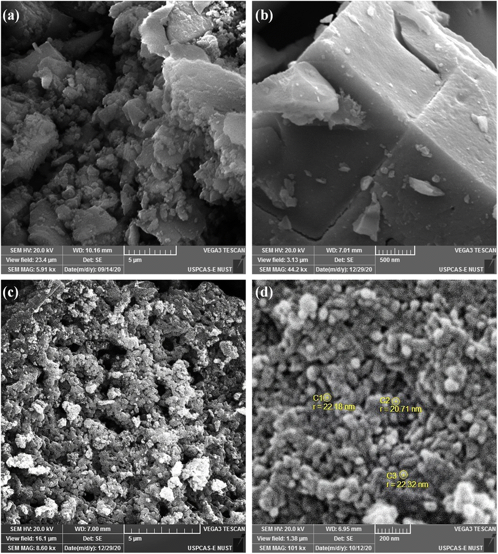 | ||
| Fig. 2 SEM images of (a and b) V-MIL-101 and (c and d) pyrolyzed nanoporous carbon structure (NVC-900). | ||
The EDS analysis in Table 1 shows the content of selected area to be consisting of vanadium metal, carbon, nitrogen, and oxygen. The content was almost constant among various sites of analysis, confirming the uniform distribution of the vanadium oxide entities along the carbon nanomatrix.
| Electrocatalyst | V-MIL-101 | NVC-900 | ||
|---|---|---|---|---|
| Wt% | At% | Wt% | At% | |
| Vanadium | 11.4 | 3.63 | 43.82 | 16.89 |
| Carbon | 41.98 | 52.36 | 34.74 | 56.79 |
| Nitrogen | 5.01 | 5.36 | 6.65 | 7.04 |
| Oxygen | 41.57 | 38.92 | 21.44 | 26.32 |
From the TEM images, a homogenously distributed porous carbon network was observed (Fig. 3a). To evaluate the presence of vanadium oxide embedded within the pores of carbon network, HAADF was performed (Fig. 3b) at a selected area. The high resolution image shows that the vanadium oxide nanoparticles are entrapped within the pores of carbon structure. This confirms the successful synthesis of a hybrid structure containing carbon backbone with encapsulated active vanadium oxide nanoparticles as further depicted in HR-TEM in Fig. 3c. The same area was also analyzed for the elemental mapping to study the distribution of elements in the structure. The Fig. 3d–f represent the presence of carbon network homogenously distributed in the highlighted area with some vanadium and oxygen species entrapped within the carbon structure as nanoparticles. This confirms that the nanoporous carbon layer has efficiently hampered the vanadium oxide nanoparticles in its spaces.
 | ||
| Fig. 3 (a) TEM images of nanoporous vanadium oxide supported carbon structure (NVC-900) (b) HAADF image of NVC-900 (c) CTEM image of vanadium oxide nanoparticle entrapped within the nanoporous carbon network (d–f) elemental mapping showing the content of carbon, vanadium and oxygen within the area under observation. | ||
The surface features and level of porosity were also analyzed by N2 adsorption–desorption isotherms using Brunner–Emmett–Teller (BET) analysis67 (Fig. 4). N2 sorption isotherms show a sharp rise at extra-low relative pressure and making a hysteresis loop at high relative pressure unravel the porous carbon structure in nanoscale. The pores develop from the release of volatile matter of metal organic framework decomposition during the thermal pyrolysis and from the cavities among the framework. The comparative analysis of V-MIL-101 and the derived NVC-900 shows that the high surface volume of the V-MIL-101 shows adsorption up to 337.8 cm3 g−1. On the other hand the thermal carbonization results into the and enhanced surface area resulting into the adsorption reaching up to a maximum level of 678.2 cm3 g−1. Moreover, the pore size distribution of NVC-900 is very well in accordance with the swift O2 transport. The corresponding desorption curves are also regenerative of the active pores necessary for an efficient complete redox process of the oxygen involving reactions.55,68,69
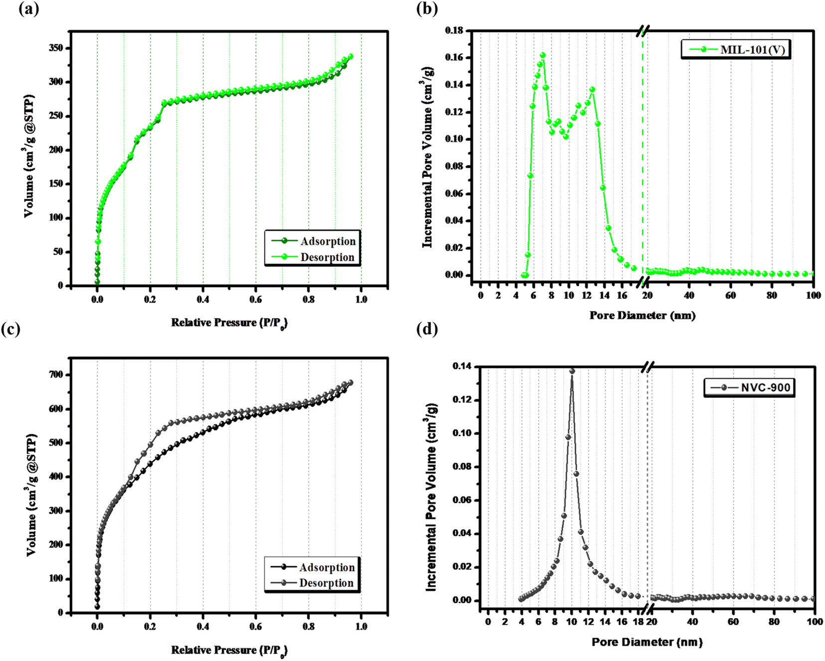 | ||
| Fig. 4 (a) N2-sorption isotherms of V-MIL-101, (b) pore size distribution curve of V-MIL-101, (c) N2-sorption isotherm of NVC-900 and (d) pore size distribution curve of NVC-900 electrocatalyst. | ||
In order to investigate bonding states of vanadium and carbon, XPS spectra were obtained (Fig. 5). Vanadium as V 2p shows two strong peaks at binding energy values of 515 eV and 517 eV. On the other hand the oxygen as O 1s shows three peaks fitted at binding energies 530 eV, 532 eV and 534 eV corresponding to bonding with vanadium, and oxygen respectively. Similarly, C 1s also shows bonding with the oxygen atoms at binding energies ranging from 285 eV to 289 eV. The most intense peak is at 284 eV which corresponds to the C–C binding in the nanoporous carbon network.
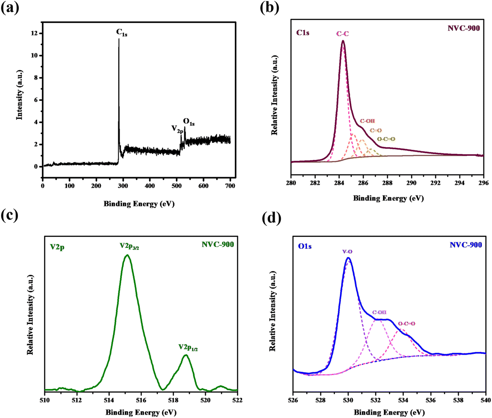 | ||
| Fig. 5 High resolution XPS spectra of (a) survey scan (b) C1s (c) V2p and (d) O1s in vanadium oxide in nanoporous carbon structure. | ||
The thermal stability of the prepared V-MIL-101 was studied by thermogravimetric analysis (TGA), as shown in Fig. 6a.70,71 The quantitative analysis of the TGA curve discloses that the initial weight loss of 8.07% from 100–200 °C is due to the escape of free and bound solvent within the sample. After the initial weight loss, the material is stable up to 340 °C with around 90% of weight retention. These results demonstrates that the vanadium metal organic framework is thermally stable up to temperatures as high as 350 °C approximately. From 350 °C onwards, a considerable loss of mass is observed which depicts the pyrolysis temperature range up to 900 °C. Within this range the V-MIL-101 undergoes decomposition and losses around 50% of the mass giving up to 45% of the original sample mass. Thus, the remaining 45% mass which is thermally treated at 900 °C is the residue containing carbon and vanadium species from decomposed vanadium metal organic framework (V-MIL-101).
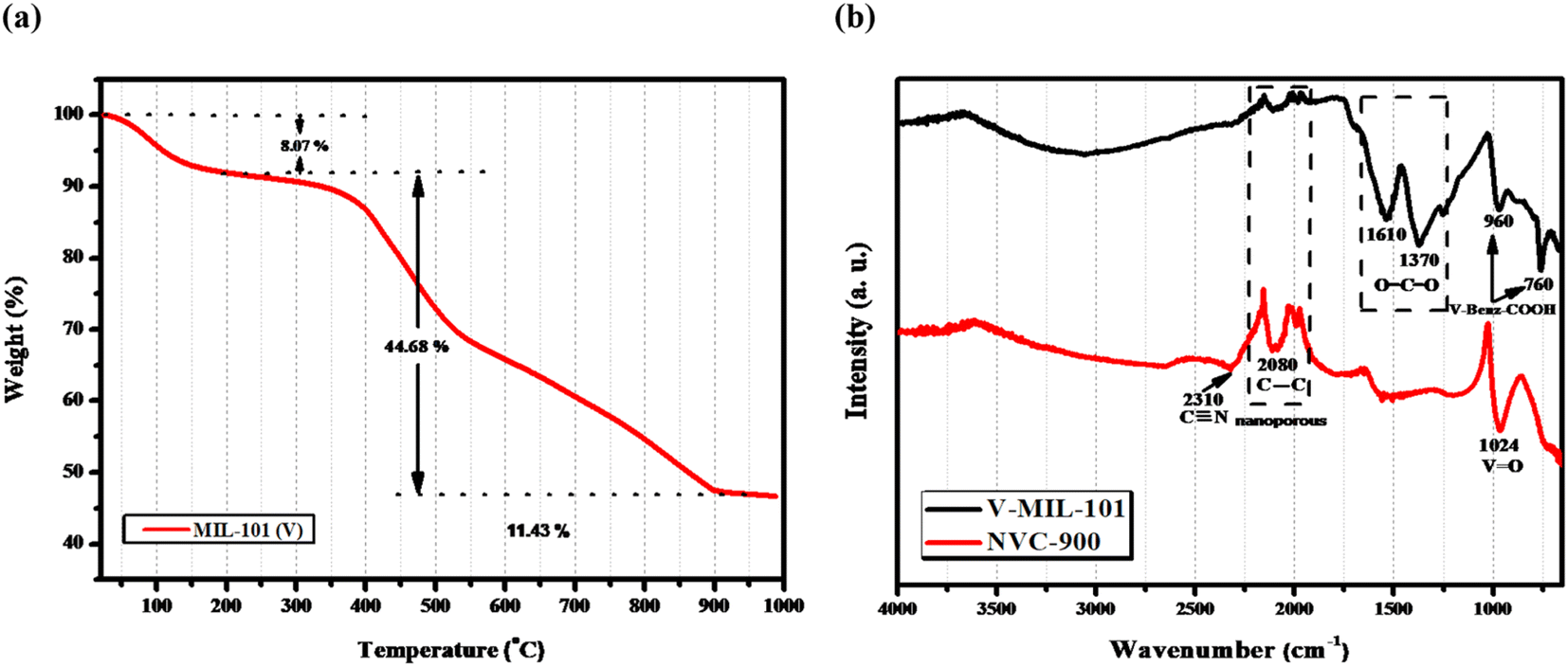 | ||
| Fig. 6 (a) TGA-DTA profile of the V-MIL-101 showing % weight retention at different temperature values (b) FTIR spectra of V-MIL-101 and derived nanoporous NVC-900. | ||
Fig. 6b displays the FTIR spectra of vanadium Metal Organic Framework and derived nanoporous vanadium oxide carbon matrix NVC-900. The FTIR spectrum of V-MIL-101 features identifying bands of vanadium bonding with terephthalate within the framework at 760 cm−1 whereas the O–C–O stretching vibration generate bands at 1370 cm−1 and 1610 cm−1.72,73 The spectrum of NVC-900 presents the identifying bands of V![[double bond, length as m-dash]](https://www.rsc.org/images/entities/char_e001.gif) O at 1024 cm−1 corresponding to the vanadium oxide nanostructures,74 and the carbon–carbon stretching band at 2080 cm−1 corresponding to carbon nanomatrix.75 The increase in the band intensity of the corresponding VO, CC and C
O at 1024 cm−1 corresponding to the vanadium oxide nanostructures,74 and the carbon–carbon stretching band at 2080 cm−1 corresponding to carbon nanomatrix.75 The increase in the band intensity of the corresponding VO, CC and C![[triple bond, length as m-dash]](https://www.rsc.org/images/entities/char_e002.gif) N linkages is due to conversion of organic framework into porous carbon structure giving rise to graphitic nitride and carbon–carbon type of bond formation along with the formation of vanadium oxide species.
N linkages is due to conversion of organic framework into porous carbon structure giving rise to graphitic nitride and carbon–carbon type of bond formation along with the formation of vanadium oxide species.
3.2. Electrochemical characterization of electrocatalyst
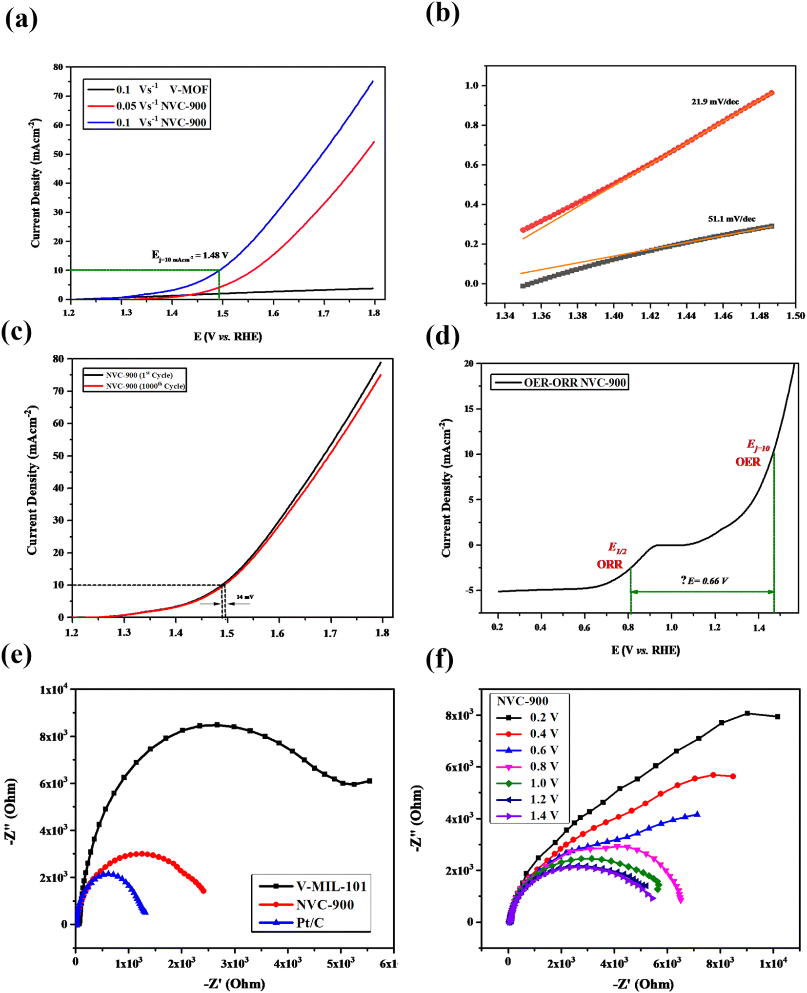
The oxygen evolution activity of the prepared nanoporous vanadium oxide supported carbon material was evaluated by using the standard three electrode system in 0.1 M KOH solution as electrolyte.68 Typically, 5 mg of active material was dissolved in 10 mL ethanol and sonicated for 30 min followed by the addition of 0.1 mL of 5 wt% Nafion and further sonication for 15 min to generate homogenous slurry. Then, 3.5 micro liters of the slurry was coated over the glassy carbon electrode surface which was equivalent 3.5 mg cm−2 of the active material actually coated on the surface of glassy carbon electrode.15 After properly drying the coated slurry, the linear sweep voltammetry (LSV) was performed.The LSV curves of the V-MIL-101 samples, pyrolyzed nanoporous NVC-900 and the 10% Pt/C, were recorded to compare the electrocatalytic performance for oxygen reduction reaction (Fig. 7a) at a scan rate of 0.1 V s−1. A current density of 5.2 mA cm−2 (denoted as limiting current density JL) with half wave potential of 0.82 V at 0.1 V s−1.
 | ||
| Fig. 7 Electrochemical analysis of bifunctional electrocatalyst: (a) ORR LSV plots of V-MIL-101, NVC-900 and 10% Pt/C at 0.1 V s−1 and 1600 RPM (b) ORR LSV plots of NVC-900 at scan rate 0.05, 0.1 and 0.15 V s−1 at 1600 rpm (c) ORR LSV curves of NVC-900 catalyst at varying rotations per minutes from 800–2000 rpm (d) Electron transfer number of NVC-900 at voltage values 0.4–0.65 V. Inset: Koutecky–Levich (K–L) plots of the NVC-900 catalyst between potentials 0.5 and 1.0 V (e) ORR Tafel slopes of NVC-900 and 10% Pt/C electrocatalysts, (f) comparison of various electrochemical parameters of all the electrocatalysts. | ||
The LSV of the nanoporous sample (NVC-900) was recorded at scan rate of 0.05, 0.1 and 0.15 V s−1 at 1600 rpm. It is clearly seen from the Fig. 7b that the current density increases with increasing the scan rate. A similar trend can also be observed by plotting LSV curves for ORR at different rotation speed (rpm) from 100 to 1600 rpm (Fig. 7c). The plots show that the value of JL is 5.2 mA cm−2 and that of E1/2 is 0.82 V. A comparison of electrocatalytic behavior of base material (MIL-101 (V)) and the derived material (NVC-900) with standard 10% Pt/C and some recently tested similar nanomaterials for ORR is presented in Table 2.
| Electrocatalyst | Onset potential (V) | Half-wave potential (V) | Limiting current density (JL) | References |
|---|---|---|---|---|
| Vanadium amino terephthalate (V-MIL-101) | 0.95 | 0.755 | 1.4 | This work |
| MOF derived nanoporous vanadium oxide carbon matrix (NVC-900) | 1.18 | 0.82 | 5.2 | This work |
| 10% Pt/C | 1.18 | 0.83 | 5.5 | This work |
| Fe-MOF derived FeS/Fe3C nanoparticles embedded in porous N,S-doped carbon (FeS/Fe3C@NS-C-900) | 1.03 | 0.78 | 6.83 | 68 |
| NiCo2O4 dodecahedron nanosheets on graphene nanosheets (NCO@GNS) | 0.85 | 0.8 | 5.0 | 76 |
| Thermally reduced mesoporous manganese MOF@reduced graphene oxide nanocomposite (Mn-BDC@75% rGO) | 1.09 | 0.98 | 2.1 | 77 |
| Cobalt based metal organic framework (Co(1,10-phenanthroline)(H2O)) | 0.83 | 0.7 | 3.65 | 26 |
The comparison shows that NVC-900 showed a promising on-set and half-wave potential as compared to 10% Pt/C catalyst with a considerably good amount of current density achieved. This leads to an alternate non-noble metal containing electrocatalyst that has the capability to compete with the expensive platinum based electrocatalyst. These values are in accordance with the literature37,40,68,76,78–82 and it also out-performs other Fe or Co containing electrocatalysts by providing better potential with considerable amount of current densities. The comparative analysis also demonstrates that our designed material can be an efficient alternative to expensive noble metal based electrocatalysts for metal air batteries.
To evaluate the ORR kinetics of NVC-900 catalyst, Koutecky–Levich (K–L) plot was drawn (Fig. 7d inset) using the following equation:83–85
 | (1) |
Therefore, the K–L equation can be described as a linear relationship given as;
 | (2) |
In eqn (2),  and
and  , where
  represents the slope, b is the intercept, while i, ik and id respectively stand for the current density of the scan, the kinetic current density and the diffusion limiting current density. F is the Faraday constant (F = 96485 C mol−1), n is the number of electron transferred during the particular scan, A is the geometric area of the rotating disk electrode, k0 is the rate constant for electron transfer, Co is the concentration of bulk oxygen (Co = 1.2 × 10⁻⁶ mol cm−3 for 0.1 M KOH), DO2 is the oxygen diffusion coefficient (DO2 = 1.9 × 10⁻⁵ cm2 s−1 for 0.1 M KOH), v is the value of viscosity (v = 0.01 cm2 s−1 for 0.1 M KOH) and w is the rotation rate (rpm) of the rotating disk electrode (RDE). The K–L plots at different potential values shows a steady state relationship between current density and rotation speed. The intercept values of the K–L curves are much greater than zero at more positive potential value which shows that the current density is the combination of both the kinetic current (ik) and diffusion-limiting current (id). Therefore, it can be stated that both the kinetic and diffusion limitations are controlling the ORR process of the synthesized material.86–88
The K–L plot shows approximate linearity which depicts the first order reaction kinetics within the potential range 0.3–0.66 V. The log of all current density values is plotted as a function of the corresponding potential values for both the nanoporous electrocatalyst NVC-900 and 10% Pt/C (Fig. 7d). The Tafel slope of the NVC-900 is 76 mV dec−1 indicating its favorable OER kinetics. The K–L plot was also used to determine the number of electrons transferred (n) within the diffusion controlled voltage range83 (Fig. 7d). The average n value is 3.9 (equal to that of Pt/C electrocatalyst) which confirms the four-electron pathway with complete oxygen reduction.
Four-electron reduction pathway (eqn (3)):
| O2 + 2H2O + 4e− → 4OH− Eo = 1.229 V vs. SHE | (3) |
In four-electron reduction pathway, the oxygen is directly reduced to hydroxide ion taking up all four electrons at once. On the other hand, during the two electron reduction pathway, oxygen is first partially reduced into unstable intermediate hydroxide ion which further reduces into hydroxide ion adding up two electrons in each step.89,90
Two-electron reduction pathway (eqn (4) and (5)):
| O2 + H2O + 2e− → HO2− + OH− Eo = 0.68 V vs. SHE | (4) |
| 2HO2− + H2O + 2e− → 3OH− Eo = 1.77 V vs. SHE | (5) |
The four-electron pathway of oxygen reduction has advantage over the two-electron mechanism. (1) The four-electron pathway involves direct reduction of oxygen into water with less positive Eo value of 1.229 V vs. SHE whereas the two-electron process involves the indirect reduction of oxygen to water via the synthesis of hydrogen peroxide species. The Eo of O2 to H2O2 conversion is 0.68 V vs. SHE which is less positive than the value of the direct four-electron reduction mechanism. Thus, the two-electron pathway is thermodynamically more difficult to carry at the first stage. Moreover, the intermediate H2O2 specie has no major significance in the oxygen reduction reaction in metal–air batteries in contrast to its role in fuel cell applications.91
The durability of the sample is an important key factor for evaluating the scope of the material for commercialization therefore, long term cycling of the sample was carried out.92,93 Quite negligible activity loss was observed after 1000 cycles in Fig. 8a and b. The half-wave potential had a negative shift of 2.1 mV in case of NVC-900 electrocatalyst which is negligible as compared to the 20 mV of negative shift in 10% Pt/C catalyst.15
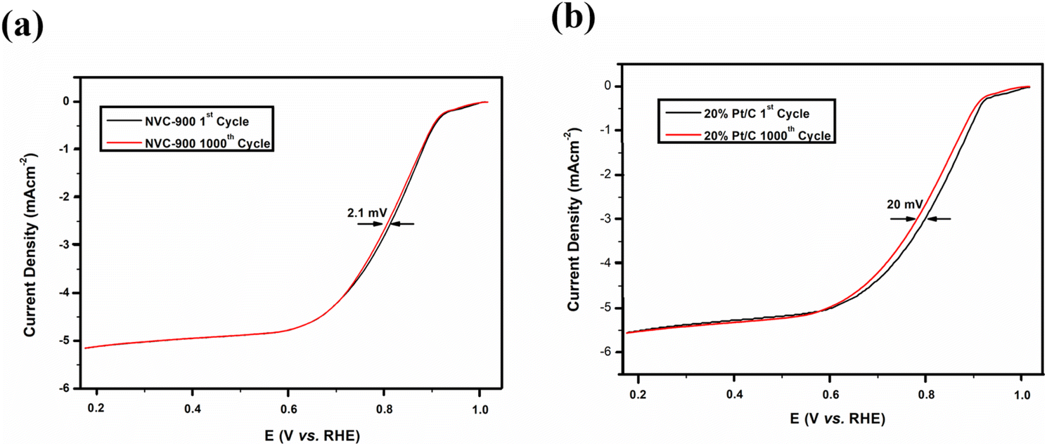 | ||
| Fig. 8 Durability test of (a) NVC-900 and (b) Pt/C for 1000 cycles for ORR. | ||
Moreover, to investigate the methanol tolerance of the bifunctional electrocatalyst, the current–time (i–t) plot was obtained in 1 M KOH where 0.05 M methanol was added to it after 600 seconds (Fig. 9). The NVC-900 electrocatalyst showed a current drop of only 25% and sustained the current for the next 3000 seconds. On the other hand, the 10% Pt/C showed a massive drop of current of about 68%. This confirms the reasonable stability and promising performance of the NVC-900 electrocatalyst in alkaline electrolyte as compared to that of 10% Pt/C.
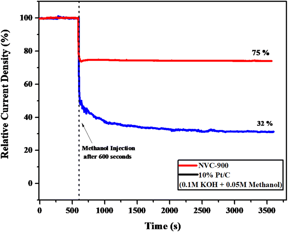 | ||
| Fig. 9 Current–time (i–t) graph of NVC-900 and 10% Pt/C in 0.1 M KOH and 0.05 M Methanol injected after 600 seconds. | ||
The OER activity of the NVC-900 bifunctional catalyst was also evaluated in N2 saturated 0.1 M KOH solution as electrolyte (Fig. 10a). The catalyst exhibited the current density of 10 mA cm−2 at a potential of 1.48 V at 0.1 V s−1 scan rate whereas the onset potential is 1.45 V. The overpotential of NVC-900 is much higher than the standard overpotential of RuO2. It still offers lesser overpotential than most of the already reported alternatives (Fig. 10b). The long-term stability of the NVC-900 electrocatalyst was also tested for OER activity for 1000 cycles as shown in Fig. 10c. A decline of 14 mV in Ej = 10 mA cm−2 was observed at the 1000th cycles.
 | ||
| Fig. 10 (a) OER LSV curves of NVC-900 electrocatalyst at scan rate 0.5, 1.0, 1.5 V s−1 (b) Tafel slopes of NVC-900 for OER (c) durability test of NVC-900 for OER for 1000 cycles. (d) Combined ORR and OER overall LSV curves of NVC-900 electrocatalyst (e) electrochemical impedance spectroscopy (EIS) plots of V-MIL-101, NVC-900 and 10% Pt/C (f) electrochemical impedance spectroscopy (EIS) plots of NVC-900 at different voltage values. | ||
A comparison of electrocatalytic behavior of base material (MIL-101 (V)), the derived material (NVC-900) and some recently tested similar nanomaterials for OER is presented in Table 3. For an overall analysis of ORR/OER bifunctional performance of the catalyst NVC-900, the potential gap (ΔE) (eqn (6)) was determined from the overall combined plot of ORR and OER68,96 (Fig. 10d).
| Electrocatalyst | Potential to achieve current density of 10 mA cm−2 (Ej = 10 mA cm−2) (V) | Overpotential (mV dec−1) | References |
|---|---|---|---|
| Vanadium amino terephthalate (V-MIL-101) | 1.56 | 51.1 | This work |
| MOF derived nanoporous vanadium oxide carbon matrix (NVC-900) | 1.48 | 21.9 | This work |
| RuO2 | 1.47 | 87 | 94 |
| Fe-MOF derived FeS/Fe3C nanoparticles embedded in porous N,S-doped carbon (FeS/Fe3C@NS-C-900) | 1.5 | 108 | 68 |
| NiCo2O4 dodecahedron nanosheets on graphene nanosheets (NCO@GNS) | 1.51 | 100 | 76 |
| Thermally reduced mesoporous manganese MOF @reduced graphene oxide nanocomposite (Mn-BDC@75% rGO) | 1.84 | 83 | 77 |
| Metal–organic framework-derived carbon nanotubes with multi-active Fe–N/Fe sites (FeNP@Fe–N–C) | 1.57 | 340 | 95 |
Where,
| ΔE = Ej=10,OER − E1/2,ORR | (6) |
To further investigate the electrochemical performance of the V-supported nanoporous carbon material, electrochemical impedance spectroscopy (EIS) was performed (Fig. 10e and f). The impedance observed by NVC-900 is clearly lower than that of V-MIL-101 whereas, the 10% Pt/C represented the least impedance as expected. As indicated by the results in Fig. 9f, the small radius of Nyquist plot was observed at values close to the standard onset potential of 0.85 V.
These findings indicate the remarkable bifunctional catalytic activity of the MOF derived nanoporous material. From the results, it is quite evident that vanadium has a favorable impact on the OER and ORR activity of the catalyst material. Moreover, the high specific surface area and nanoporous morphology of the pyrolyzed carbon-based structure reinforced the oxygen diffusion process upon the active catalytic sites.
4. Conclusion
A vanadium oxide supported nanoporous carbon structured with hierarchical nanoporous morphology was prepared via pyrolysis of the three-dimensional vanadium metal organic framework (V-MIL-101). The prepared catalyst material exhibited excellent bifunctional catalytic activity for both oxygen evolution and oxygen reduction reaction and outperformed many conventional noble-metals based electrocatalysts. The observed electrocatalytic activity of the prepared sample is attributed to the excess amount of easily accessible active sites, large surface area and uniformly distributed nanopores. Excellent electrochemical behavior of highly stable vanadium oxide played its role in swift single step reduction of oxygen through the four-electron mechanism. Therefore, good limiting current density of 5.2 mA cm−2 with low onset potential of 0.82 V for ORR is observed, being almost as good as Pt. On the other hand, for OER 10 mA cm−2 of current density is observed at potential of 1.48 V, with least amount of impedance offered in the same potential range. We believe that strategy adopted in this work will open the avenue for designing novel bifunctional electrocatalysts beyond Pt for application in next generation high-energy storage devices. The active vanadium oxide nanoparticles were embedded within the high surface area nanoporous carbon structure. The novelty of the current study has three aspects: (1) the facile synthesis of a well-designed structure with multiple nano-architectural advantages, (2) redox active sites of vanadium along with the uniformly distributed porous surface provided by carbon structure enabling wide exposure to the active sites, (3) the electrochemical performance as dual-functional active electrocatalyst with performance as good as standard electrocatalysts but cost effective as compared to expensive Pt based commercial electrocatalysts. Ample porosity achieved from this method increases the density of exposed active sites which expedite the charge transfer. Well-dispersed uniform porous carbon nanostructures offer more structural stability whereas enough nitrogen species coming from amino terephthalic acid act as additional active sites for ORR.Conflicts of interest
The authors declare that they have no known competing financial interests or personal relationships that could have appeared to influence the work reported in this paper.Acknowledgements
The authors would like to acknowledge the financial support from USAID, Pakistan Science Foundation (PSF) under Project No. LCF-05 and Higher Education Commission (HEC) Pakistan for the financial support under Project No. CPEC-CRG-149.References
- M. J. Song, I. T. Kim, Y. B. Kim and M. W. Shin, Electrochim. Acta, 2015, 182, 289–296 CrossRef CAS.
- B. Scrosati, K. Abraham, W. A. van Schalkwijk and J. Hassoun, Lithium Batteries: Advanced Technologies and Applications, John Wiley & Sons, 2013 Search PubMed.
- R. Mori, Electrochem. Energy Rev., 2020, 3, 344–369 CrossRef CAS.
- R. Devanathan, Energy Environ. Sci., 2008, 1, 101–119 RSC.
- T. M. Gür, Energy Environ. Sci., 2018, 11, 2696–2767 RSC.
- P. Tan, B. Chen, H. Xu, H. Zhang, W. Cai, M. Ni, M. Liu and Z. Shao, Energy Environ. Sci., 2017, 10, 2056–2080 RSC.
- Y. Li and J. Lu, ACS Energy Lett., 2017, 2, 1370–1377 CrossRef CAS.
- Q. Liu, Z. Pan, E. Wang, L. An and G. Sun, Energy Storage Mater., 2020, 27, 478–505 CrossRef.
- J. Zhang, Z. Zhao, Z. Xia and L. Dai, Nat. Nanotechnol., 2015, 10, 444–452 CrossRef CAS PubMed.
- W. Ying, Z. Limin and H. Tianjun, Acta Chim. Sin., 2015, 73, 316–325 CrossRef.
- L. Du, G. Zhang, X. Liu, A. Hassanpour, M. Dubois, A. C. Tavares and S. Sun, Carbon Energy, 2020, 2, 561–581 CrossRef CAS.
- F. Cheng and J. Chen, Chem. Soc. Rev., 2012, 41, 2172–2192 RSC.
- L. Zhang, L. T. Roling, X. Wang, M. Vara, M. Chi, J. Liu, S.-I. Choi, J. Park, J. A. Herron and Z. Xie, Science, 2015, 349, 412–416 CrossRef CAS PubMed.
- L. Bu, N. Zhang, S. Guo, X. Zhang, J. Li, J. Yao, T. Wu, G. Lu, J.-Y. Ma and D. Su, Science, 2016, 354, 1410–1414 CrossRef CAS PubMed.
- S. Hanif, X. Shi, N. Iqbal, T. Noor, R. Anwar and A. Kannan, Appl. Catal., B, 2019, 258, 117947 CrossRef CAS.
- R. Anwar, N. Iqbal, S. Hanif, T. Noor, X. Shi, N. Zaman, D. Haider, S. A. M Rizvi and A. Kannan, Catalysts, 2020, 10, 799 CrossRef CAS.
- H. Zhang, Y. Luo, P. K. Chu, Q. Liu, X. Liu, S. Zhang, J. Luo, X. Wang and G. Hu, J. Alloys Compd., 2022, 166113 CrossRef CAS.
- M. Ledendecker, G. Clavel, M. Antonietti and M. Shalom, Adv. Funct. Mater., 2015, 25, 393–399 CrossRef CAS.
- X. Liu, M. Park, M. G. Kim, S. Gupta, G. Wu and J. Cho, Angew. Chem., Int. Ed., 2015, 54, 9654–9658 CrossRef CAS PubMed.
- D. Wang, H. L. Xin, R. Hovden, H. Wang, Y. Yu, D. A. Muller, F. J. DiSalvo and H. D. Abruña, Nat. Mater., 2013, 12, 81–87 CrossRef CAS PubMed.
- A. Zhao, J. Masa, W. Xia, A. Maljusch, M.-G. Willinger, G. Clavel, K. Xie, R. Schlögl, W. Schuhmann and M. Muhler, J. Am. Chem. Soc., 2014, 136, 7551–7554 CrossRef CAS PubMed.
- J. Masa, W. Xia, I. Sinev, A. Zhao, Z. Sun, S. Grützke, P. Weide, M. Muhler and W. Schuhmann, Angew. Chem., Int. Ed., 2014, 53, 8508–8512 CrossRef CAS PubMed.
- E. Davari and D. Ivey, Sustainable Energy Fuels, 2018, 2, 39–67 RSC.
- Z. P. Wu, X. F. Lu, S. Q. Zang and X. W. Lou, Adv. Funct. Mater., 2020, 30, 1910274 CrossRef CAS.
- K. Surya, M. Michael and S. Prabaharan, Solid State Ionics, 2018, 317, 89–96 CrossRef CAS.
- D. Bagchi, N. Phukan, S. Sarkar, R. Das, B. Ray, P. Bellare, N. Ravishankar and S. C. Peter, J. Mater. Chem. A, 2021, 9, 9319–9326 RSC.
- Q. Pan and L. Wang, J. Power Sources, 2021, 485, 229335 CrossRef CAS.
- L. Wei, E. H. Ang, Y. Yang, Y. Qin, Y. Zhang, M. Ye, Q. Liu and C. C. Li, J. Power Sources, 2020, 477, 228696 CrossRef CAS.
- F. X. L. Xamena and J. Gascon, Metal Organic Frameworks as Heterogeneous Catalysts, Royal Society of Chemistry, 2013 Search PubMed.
- F. Kong, X. Fan, A. Kong, Z. Zhou, X. Zhang and Y. Shan, Adv. Funct. Mater., 2018, 28, 1803973 CrossRef.
- B. Liu, H. Shioyama, T. Akita and Q. Xu, J. Am. Chem. Soc., 2008, 130, 5390–5391 CrossRef CAS PubMed.
- Q. Wang, W. Zhang, C. Guo, Y. Liu, C. Wang and Z. Guo, Adv. Funct. Mater., 2017, 27, 1703390 CrossRef.
- C. Wei, M. Shen, K. Ai and L. Lu, Carbon, 2017, 123, 135–144 CrossRef CAS.
- H. Chen, X. Ma and P. K. Shen, J. Alloys Compd., 2019, 779, 193–201 CrossRef CAS.
- R. Mehek, N. Iqbal, T. Noor, H. Nasir, Y. Mehmood and S. Ahmed, Electrochim. Acta, 2017, 255, 195–204 CrossRef CAS.
- J. Liu, D. Zhu, C. Guo, A. Vasileff and S. Z. Qiao, Adv. Energy Mater., 2017, 7, 1700518 CrossRef.
- L. Yang, X. Zeng, W. Wang and D. Cao, Adv. Funct. Mater., 2018, 28, 1704537 CrossRef.
- D. Liu, J. Wan, G. Pang and Z. Tang, Adv. Mater., 2019, 31, 1803291 CrossRef PubMed.
- J. Zhou, Y. Dou, A. Zhou, R. M. Guo, M. J. Zhao and J. R. Li, Adv. Energy Mater., 2017, 7, 1602643 CrossRef.
- L. Li, P. Dai, X. Gu, Y. Wang, L. Yan and X. Zhao, J. Mater. Chem. A, 2017, 5, 789–795 RSC.
- S. Ashraf, R. Mehek, N. Iqbal, T. Noor, G. Ali, A. Wahab, A. A. Qayyum and A. Ahmad, Mater. Chem. Phys., 2021, 124824 CrossRef CAS.
- G. Goenaga, S. Ma, S. Yuan and D.-J. Liu, ECS Trans., 2010, 33, 579–586 CrossRef CAS.
- M. Lefèvre, E. Proietti, F. Jaouen and J.-P. Dodelet, Science, 2009, 324, 71–74 CrossRef PubMed.
- J. Yang, B. Wang, F. Jin, Y. Ning, H. Luo, J. Zhang, F. Wang, D. Wang and Y. Zhou, Nanoscale, 2020, 12, 4552–4561 RSC.
- Z. Wang, X. Li, Y. Cui, Y. Yang, H. Pan, Z. Wang, C. Wu, B. Chen and G. Qian, Cryst. Growth Des., 2013, 13, 5116–5120 CrossRef CAS.
- K. Barthelet, J. Marrot, G. Férey and D. Riou, Chem. Commun., 2004, 520–521 RSC.
- W. Kaveevivitchai and A. J. Jacobson, J. Power Sources, 2015, 278, 265–273 CrossRef CAS.
- M. Z. Arif, N. Iqbal, R. Mahek, T. Noor and A. Khan, J. Mater. Sci.: Mater. Electron., 2021, 1–13 Search PubMed.
- H. Huang, A. Liu, Q. Kang, X. Ye, H. Chen, W.-N. Su and T. Ma, Mater. Today Energy, 2022, 25, 100968 CrossRef CAS.
- S. Dang, Q.-L. Zhu and Q. Xu, Nat. Rev. Mater., 2017, 3, 1–14 Search PubMed.
- M. H. Yap, K. L. Fow and G. Z. Chen, Green Energy Environ., 2017, 2, 218–245 CrossRef.
- Z. Liang, R. Zhao, T. Qiu, R. Zou and Q. Xu, EnergyChem, 2019, 1, 100001 CrossRef.
- T. Palaniselvam, B. P. Biswal, R. Banerjee and S. Kurungot, Chem.–Eur. J., 2013, 19, 9335–9342 CrossRef CAS PubMed.
- R. Ahmad, N. Iqbal, M. M. Baig, T. Noor, G. Ali and I. H. Gul, Electrochim. Acta, 2020, 364, 137147 CrossRef CAS.
- A. Brückner and M. Baerns, Appl. Catal., A, 1997, 157, 311–334 CrossRef.
- J. Wang, H. He, L. Li and D. Wang, Sci. Sin.: Chim., 2014, 44, 1313–1324 CAS.
- L. Liu, X. Wang and A. Jacobson, J. Mater. Res., 2009, 24, 1901–1905 CrossRef CAS.
- F. Carson, J. Su, A. E. Platero-Prats, W. Wan, Y. Yun, L. Samain and X. Zou, Cryst. Growth Des., 2013, 13, 5036–5044 CrossRef CAS.
- J. Yang, M. Wu, F. Gong, T. Feng, C. Chen and J. Liao, RSC Adv., 2017, 7, 24418–24424 RSC.
- S. Zhu, A. Huang, Q. Wang and Y. Xu, Nanotechnology, 2021, 32, 165401 CrossRef CAS PubMed.
- M. J. Song, I. T. Kim, Y. B. Kim, J. Kim and M. W. Shin, Electrochim. Acta, 2017, 230, 73–80 CrossRef CAS.
- M. Lee, S. K. Balasingam, H. Y. Jeong, W. G. Hong, B. H. Kim and Y. Jun, Sci. Rep., 2015, 5, 1–8 Search PubMed.
- X. Liu, L. Zhang and J. Wang, Journal of Materiomics, 2021, 7, 440–459 CrossRef.
- Y. Li, Z. Y. Fu and B. L. Su, Adv. Funct. Mater., 2012, 22, 4634–4667 CrossRef CAS.
- M. M. Dehcheshmeh, R. K. Shervedani and M. Torabi, Electrochim. Acta, 2019, 327, 134895 CrossRef CAS.
- M. Mirzaeian and P. J. Hall, Electrochim. Acta, 2009, 54, 7444–7451 CrossRef CAS.
- Z. Song, L. Miao, L. Ruhlmann, Y. Lv, D. Zhu, L. Li, L. Gan and M. Liu, Adv. Funct. Mater., 2022, 32(48), 2208049 CrossRef CAS.
- Y.-W. Li, W.-J. Zhang, J. Li, H.-Y. Ma, H.-M. Du, D.-C. Li, S.-N. Wang, J.-S. Zhao, J.-M. Dou and L. Xu, ACS Appl. Mater. Interfaces, 2020, 12, 44710–44719 CrossRef CAS PubMed.
- Y. Yin, Z. Wen, L. Shi, Z. Zhang, Z. Yang, C. Xu, H. Sun, S. Wang and A. Yuan, ACS Sustainable Chem. Eng., 2019, 7, 11284–11292 CrossRef CAS.
- A. Lieb, H. Leclerc, T. Devic, C. Serre, I. Margiolaki, F. Mahjoubi, J. S. Lee, A. Vimont, M. Daturi and J.-S. Chang, Microporous Mesoporous Mater., 2012, 157, 18–23 CrossRef CAS.
- Y. Y. Liu, K. Leus, M. Grzywa, D. Weinberger, K. Strubbe, H. Vrielinck, R. Van Deun, D. Volkmer, V. Van Speybroeck and P. Van Der Voort, Eur. J. Inorg. Chem., 2012, 2012, 2819–2827 CrossRef CAS.
- R. S. De Oliveira, W. A. Alves and E. A. Ponzio, ECS Trans., 2012, 43, 363 CrossRef CAS.
- H. Zhang, Y. Yi, D. Feng, Y. Wang and S. Qin, Evid. base Compl. Alternative Med., 2011, 2011, 691067 Search PubMed.
- C. O'Dwyer, V. Lavayen, S. B. Newcomb, M. A. Santa Ana, E. Benavente, G. Gonzalez and C. S. Torres, J. Electrochem. Soc., 2007, 154, K29 CrossRef.
- M. Fattahi, M. Kazemeini, F. Khoraasheh and A. M. Rashid, Ind. Eng. Chem. Res., 2013, 52(46), 16128–16141 CrossRef CAS.
- R. Palani, C. Karuppiah, C.-C. Yang and S. Piraman, Int. J. Hydrogen Energy, 2021, 46, 14288–14300 CrossRef CAS.
- A. Wahab, N. Iqbal, T. Noor, S. Ashraf, M. A. Raza, A. Ahmad and U. A. Khan, RSC Adv., 2020, 10, 27728–27742 RSC.
- Q. Ren, H. Wang, X. F. Lu, Y. X. Tong and G. R. Li, Adv. Sci., 2018, 5, 1700515 CrossRef PubMed.
- J. Gao, N. Ma, Y. Zheng, J. Zhang, J. Gui, C. Guo, H. An, X. Tan, Z. Yin and D. Ma, ChemCatChem, 2017, 9, 1601–1609 CrossRef CAS.
- Y. Tong, P. Chen, T. Zhou, K. Xu, W. Chu, C. Wu and Y. Xie, Angew. Chem., Int. Ed., 2017, 56, 7121–7125 CrossRef CAS PubMed.
- X. Mao, C. Ling, C. Tang, C. Yan, Z. Zhu and A. Du, J. Catal., 2018, 367, 206–211 CrossRef CAS.
- H. He, M. Wang, J. Zhao and Y. Zhang, Chem. Eng. J., 2017, 316, 680–691 CrossRef CAS.
- R. Zhou, Y. Zheng, M. Jaroniec and S.-Z. Qiao, ACS Catal., 2016, 6, 4720–4728 CrossRef CAS.
- P. Strasser, Acc. Chem. Res., 2016, 49, 2658–2668 CrossRef CAS PubMed.
- B. Feng, X. Wu, Y. Niu, W. Li, Y. Yao, W. Hu and C. M. Li, Sustainable Energy Fuels, 2019, 3, 3455–3461 RSC.
- Y.-H. Shih, G. V. Sagar and S. D. Lin, J. Phys. Chem. C, 2008, 112, 123–130 CrossRef CAS.
- O. Antoine, Y. Bultel and R. Durand, J. Electroanal. Chem., 2001, 499, 85–94 CrossRef CAS.
- A. Zana, G. K. Wiberg, Y.-J. Deng, T. Østergaard, J. Rossmeisl and M. Arenz, ACS Appl. Mater. Interfaces, 2017, 9, 38176–38180 CrossRef CAS PubMed.
- H. Wang, F. Yin, G. Li, B. Chen and Z. Wang, Int. J. Hydrogen Energy, 2014, 39, 16179–16186 CrossRef CAS.
- N. M. Markovic, H. A. Gasteiger and P. N. Ross, J. Phys. Chem., 1996, 100, 6715–6721 CrossRef.
- S. Fukuzumi, Y.-M. Lee and W. Nam, ChemCatChem, 2018, 10, 9–28 CrossRef CAS.
- B. Wang, Y. Ye, L. Xu, Y. Quan, W. Wei, W. Zhu, H. Li and J. Xia, Adv. Funct. Mater., 2020, 30, 2005834 CrossRef CAS.
- Y.-J. Wang, B. Fang, D. Zhang, A. Li, D. P. Wilkinson, A. Ignaszak, L. Zhang and J. Zhang, Electrochem. Energy Rev., 2018, 1, 1–34 CrossRef CAS.
- D. Chakraborty, S. Nandi, R. Illathvalappil, D. Mullangi, R. Maity, S. K. Singh, S. Haldar, C. P. Vinod, S. Kurungot and R. Vaidhyanathan, ACS Omega, 2019, 4, 13465–13473 CrossRef CAS PubMed.
- C. Yang, S. Shang, Q. Gu, J. Shang and X.-y. Li, J. Energy Chem., 2022, 66, 306–313 CrossRef CAS.
- J. Zhang, M. Zhang, Y. Zeng, J. Chen, L. Qiu, H. Zhou, C. Sun, Y. Yu, C. Zhu and Z. Zhu, Small, 2019, 15, 1900307 CrossRef PubMed.
| This journal is © The Royal Society of Chemistry 2023 |