
 Open Access Article
 This Open Access Article is licensed under a Creative Commons Attribution-Non Commercial 3.0 Unported Licence
Functionally gradient three-dimensional graphene foam-based polymeric scaffolds for multilayered tissue regeneration†
Pallavi Guptaa,
Sonali Waghmarea,
Srabani Karb,
Kavitha Illatha,
Suresh Rao *a and
Tuhin Subhra Santra*a
*a and
Tuhin Subhra Santra*a
aDepartment of Engineering Design, Indian Institute of Technology Madras, Chennai 600036, India. E-mail: chennaidentist@gmail.com; tuhin@iitm.ac.in; Tel: +91-9840041787 Tel: +91-044-2257-4747
bIndian Institute of Science Education and Research, Tirupati 517507, India
First published on 4th January 2023
Abstract
Physiological bioengineering of multilayered tissues requires an optimized geometric organization with comparable biomechanics. Currently, polymer-reinforced three-dimensional (3D) graphene foams (GFs) are gaining interest in tissue engineering due to their unique morphology, biocompatibility, and similarity to extracellular matrixes. However, the homogeneous reinforcement of single polymers throughout a GF matrix does not provide tissue-level organization. Therefore, a triple-layered structure is developed in a GF matrix to closely mimic native tissue structures of the periodontium of the teeth. The scaffold aims to overcome the issue of layer separation, which generally occurs in multilayered structures due to the poor integration of various layers. The 3D GF matrix was reinforced with a polycaprolactone (PCL), polyvinyl alcohol (PVA), and PCL-hydroxyapatite (HA) mixture, added sequentially, via spin coating, vacuum, and hot air drying. Later, PVA was dissolved to create a middle layer, mimicking the periodontal fibers, while the layers present on either side resembled cementum and alveolar bone, respectively. Scanning electron microscopy and micro-computed tomography revealed the structure of the scaffold with internal differential porosities. The nanoindentation and tensile testing demonstrated the closeness of mechanical properties to that of native tissues. The biocompatibility was assessed by the MTT assay with MG63 cells (human osteosarcoma cells) exhibiting high adhesion and proliferation rate inside the 3D architecture. Summing up, this scaffold has the potential for enhancing the regeneration of various multilayered tissues.
1. Introduction
Graphene has shown great prospects in diverse fields such as engineering, energy, biosystems, and environmental science as it has fascinating properties such as a large surface area, thermal conductivity, electrical conductivity, and mechanical strength.1–4 However, due to high surface energies, the graphene sheets tend to agglomerate, thereby compromising their properties in composites.5 However, the recent development of the three-dimensional graphene foams (3D-GFs) in the form of an interconnected continuous graphene network prevents agglomeration and facilitates the uniform distribution of graphene in composites.6,7 In the field of tissue engineering and regenerative medicine, 3D-GFs are ideal candidates for the preparation of promising novel scaffolds by simultaneously providing topographical, chemical, mechanical, and electrical cues in the same scaffold.7–11 The 3D-GFs also exhibit structural similarities to the microenvironment of natural tissues. The 3D microenvironment of GFs has the potential to induce stem cells to preferentially differentiate into specific lineages, particularly various neuronal and musculoskeletal lineages.9,12 The huge interfacial area and 3D multiplexing allow nutrients and waste transport along with electron transport, thus facilitating electrical coupling and augmentation of electrical stimulation of cells.13Initially, the pristine 3D graphene foam was used in different situations, such as neural stem cell proliferation and differentiation,9 and the assessment of anti-inflammatory behaviour of microglial cells on 3D graphene foam over 2D graphene structures.14 GF-reinforced polymers demonstrate exceptional mechanical strength composites in terms of toughness, ductility, tensile strength, and flexibility, as shown by recovery, post 80% compression strain.15 Nieto et al. proposed the application of a 3D graphene foam/polymer composite in tissue engineering as a scaffold with superior strength, high flexibility, and biocompatibility8 and since then the same concept has been adapted by various researchers. Li et al. fabricated a 3D graphene oxide foam/polydimethylsiloxane/zinc silicate (GF/PDMS/ZS) scaffold that facilitated bone regeneration employing dip coating and hydrothermal synthesis processes. Both in vitro and in vivo experiments were conducted to establish the scaffold bone regeneration capabilities. The scaffold-induced mouse-bone-marrow mesenchymal stem cell (mBMSC) proliferation and preferential osteogenetic differentiation.16 Also, the critical bone defect analysis in rabbits revealed the GF/PDMS/ZS scaffold-supported bone formation post-12 week implantation with insignificant inflammatory immune reactions.16 The polycaprolactone (PCL)-reinforced 3D-GFs were rolled to form a three-dimensional nerve guide conduit as well.17 All of the above-mentioned scaffolds showed improved mechanical integrity over pristine GF, with enhancement in biocompatibility owing to the polymer reinforcement.
Therefore, in this study, we attempted to form three distinct layers in GFs to overcome the drawbacks, such as layer delamination due to poor adhesion among different layers of scaffolds along with low mechanical integrity as mentioned earlier. To prepare such a complex scaffold, we considered the supporting structures of the tooth, periodontium, with three tissues as a model. This is a unique tissue with soft tissue fibers (periodontal fibers) anchored to two hard tissues (bone and cementum). The requirements are scaffolds of different modulus of elasticity, a variable width of the structures, and most importantly, anchoring of fibers into the hard tissues.
We used the spin coating and vacuum/hot air drying process to prepare the multi-layered structure within a single matrix, i.e., GF. The fabricated structures were investigated for their structural and mechanical properties to establish a three-layered functionally-gradient scaffold. The internal porosities of the different layers were shown via micro-computed tomography (CT), while mechanical properties were assessed with tensile testing and nanoindentation. Different cell lines were cultured on the 3D scaffold, such as MG63 cells (human osteosarcoma cells), Huh 7 (liver cells), and N2a cells (neuron cells). The schematic for the complete fabrication process and application is depicted in Fig. 1.
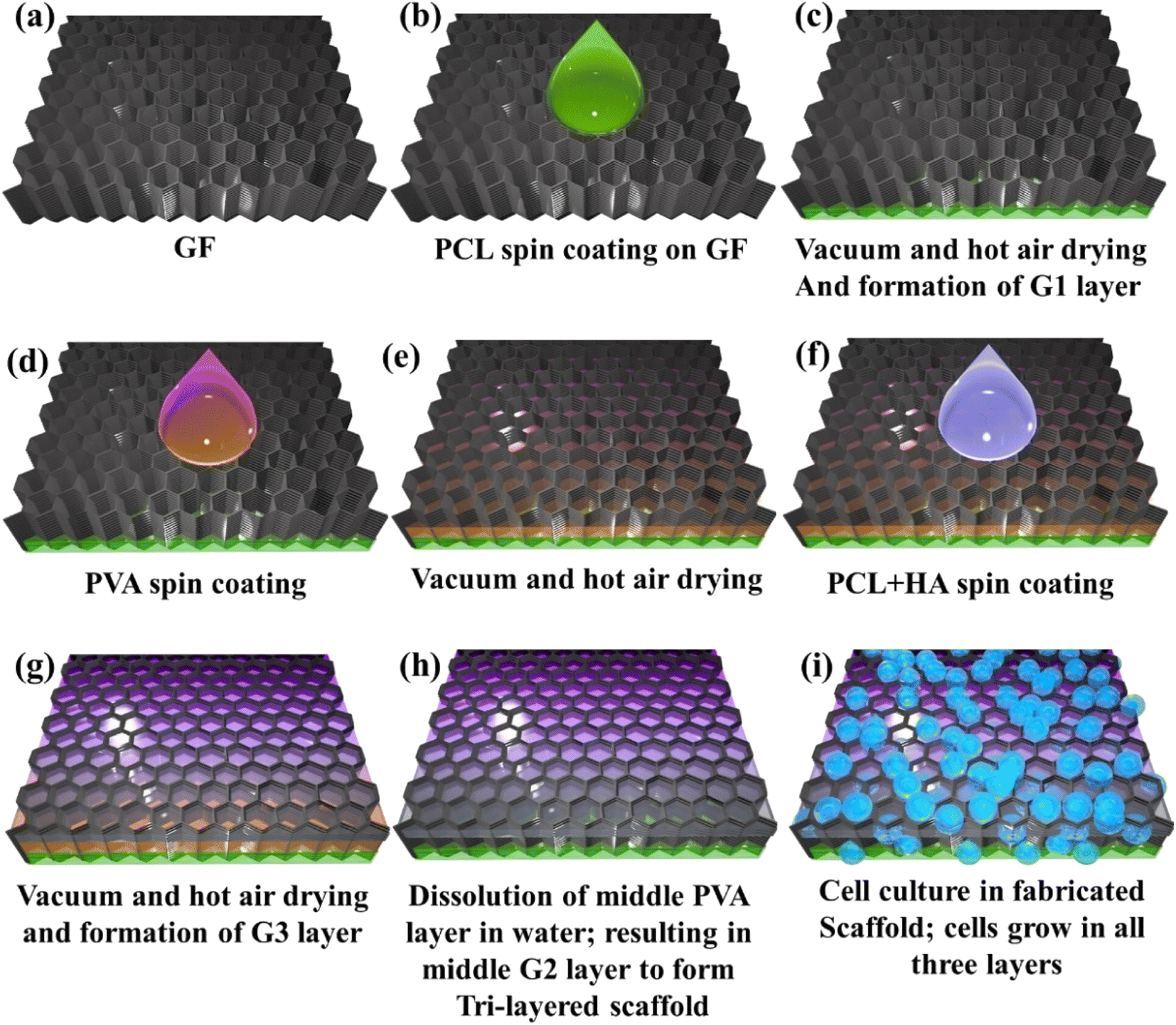 | ||
| Fig. 1 Schematic showing a complete fabrication and process steps for the trilayered GF-based scaffold. | ||
2. Materials and methods
2.1. Materials used
Materials used in the experiments are described below and were used as received. The 3D multilayer free-standing graphene foam (GF, thickness 1.2 mm) was purchased from Ultrananotech Pvt. Ltd. (Bangalore, India). Polycaprolactone (PCL, avg. Mn 80![[thin space (1/6-em)]](https://www.rsc.org/images/entities/char_2009.gif) 000) and polyvinyl alcohol (PVA, avg. Mn 30000–70000) were ordered from Sigma-Aldrich (USA). Chloroform (CHCl3, Mn 119.38) was purchased from Sisco Research Laboratories (New Mumbai, India). Hydroxyapatite (HA) granules (size: 0.355–0.5 mm) were purchased from Kuber Medical Pvt. Ltd. (Delhi, India).
000) and polyvinyl alcohol (PVA, avg. Mn 30000–70000) were ordered from Sigma-Aldrich (USA). Chloroform (CHCl3, Mn 119.38) was purchased from Sisco Research Laboratories (New Mumbai, India). Hydroxyapatite (HA) granules (size: 0.355–0.5 mm) were purchased from Kuber Medical Pvt. Ltd. (Delhi, India).
2.2. Scaffold fabrication
The pristine GF (obtained from Ultrananotech Pvt. Ltd., Bangalore, India), named G0, was cut into squares of size 15 mm × 15 mm. Initially, to increase the handleability of G0, the coating was performed with 4% wt PCL solution (in chloroform). Then, 1 ml of the measured volume of 15% wt. PCL solution was spin-coated onto the G0 film at 1000 rpm for 60 seconds followed by vacuum drying for 10 minutes. Further, it was cured in an oven for 30 minutes at 60 °C. This completed the fabrication of the first layer of PCL on G0 and it was named the G1 stage. The G1 was supposed to mimic cementum characteristics as in periodontium. Further, the PVA solution was used to fabricate the sacrificial second layer onto this film (i.e., G1:G0 with PCL coating). The 10% wt. PVA solution (1 ml) was spin-coated on G1 at 1000 rpm for 60 seconds. Then, this layer was cured in an oven for 30 min at 60 °C. Thus, a layer of PVA was fabricated on G1, which was to be dissolved later to form a porous middle layer named G2. The PCL/HA solution was utilized as a coating solution to fabricate the third layer on G0. “The PCL/HA solution consisted of 15% wt PCL and 4% HA”. The third layer was fabricated by taking 1 ml of the solution and spin-coating on G2 at 1000 rpm for 60 s. Further, it was vacuum dried for 10 min and cured in an oven for 30 min at 60 °C. It was also kept at room temperature to dry it thoroughly. The layer was coated to ensure a flat finish on the top side and named G3. This layer was supposed to mimic characteristics of the cortical bone as in periodontium. The middle layer in the periodontium is a periodontal ligament (PDL), a fibrous network. To achieve the fibrous structure between G1 and G3, the sample was introduced into DI water using a magnetic stirrer for 1 hour at 50 °C, and thus water-soluble middle PVA layer was dissolved. It was then dried at room temperature to ensure G3 was free from DI water. Thus, the final form of the G3 layer was obtained. After dissolution, a porous structure appeared in the middle with a thin coating of PCL. This fibrous layer mimics the PDL characteristics in the periodontium. By using this technique, the fabrication of a 3D scaffold consisting of GF with three distinct layers was performed and it could mimic the multilayered tissue structure as depicted in Fig. 1. Also, the fabrication process is clearly presented in Table 1.| Name | Coating material | Coating process | Curing |
|---|---|---|---|
| G0 | Native GF | — | — |
| G1 | 15% wt PCL | Spin-coating (1000 rpm for 60 s) | Vacuum drying (10 minutes) |
| G2 | 10% wt PVA | Spin-coating (1000 rpm for 60 s) | Dry heating in the oven for 30 min at 60 °C |
| After the curing of the G3 layer, the dissolution of PVA inside DI water using a magnetic stirrer for 1 hour at 50 °C | |||
| G3 | PCL/HA solution consisted of 15% wt PCL and 4% HA | Spin-coating (1000 rpm for 60 s) | Vacuum drying for 10 min followed by dry heating for 30 min at 60 °C |
2.3. Structural characterization
The morphology of the three-layer graphene foam was characterized using a scanning electron microscope (SEM; Apreo S, Thermo Scientific, Octane Elite EDS system). The samples were sputter-coated with gold (10 nm) (Polaron SC7640, Quorum Technologies) for 120 s. After that, the images were taken with 10 kV accelerating potential.The different layers formed in the 3D GF scaffold were also imaged using micro-CT imaging (GE Phoenix VTOMEX CT Scanner) in order to obtain porosity. The scan data were acquired using an X-ray tube setting of 30 kV, 500 μA, and an exposure time of 600 ms with a resolution of 27 nm. Then, ImageJ software was used to analyze the porosity of different layers and the branch thickness of the graphene foam acquired from micro-CT imaging.
Confocal Raman spectroscopy was performed using WITEC alpha 300R equipment excited using the Nd-YAG laser (wavelength: 532 nm) as a source with a range between 100 cm−1 and 3600 cm−1.
2.4. Mechanical characterization
The nanoindentation was performed on the samples using a TI-Premium (Hysitron Inc., Minneapolis, MN, USA) instrument with a Berkovich indenter for mechanical characterization. The maximum load was kept at 10 mN, while the maximum depth was 5 microns. Tensile testing on the GF scaffold was performed using the micro tensile testing system, over a load range of 20 mN to 2 kN. The system had an ultrahigh precision drive system (20 nm position resolution) for micro-position displacement control with high-accuracy load measurements. The dimension of the sample were 15 mm × 5 mm, 8 mm gauge length, and 200 μm thickness. The experiments were performed at a cross-head speed of 0.1 mm s−1. Three specimens of each type were tested and the average values were tabulated.2.5. Cell culture
The biocompatibility test of the scaffolds was performed via in vitro cell culture. Initially, the scaffolds were treated with 70% IPA (isopropyl alcohol) and ultraviolet (UV) light prior to cell culture for sterilization. Then, osteoblast-like cells (MG63)18 were used as a model to assess cell behavior on the scaffolds. The live and dead cell staining was performed using Calcein AM (Invitrogen, catalogue no. C3099) and propidium iodide (PI) dye (Invitrogen, catalogue no. 32042090).19 Briefly, cells were cultured on a scaffold for 2 days in DMEM high glucose cell culture medium, and post-incubation 30 μl calcein AM was added to the scaffold. The scaffold was incubated for 10 min at 37 °C temperature and 5% CO2 incubator, after that 10 μl PI dye was introduced. Then, a fluorescence microscope (DP72, Olympus, Japan) was used to capture the images for analysis purposes.3. Results
3.1. Microstructural characterization
The morphology and composition of individual layers G1, G2, and G3 along with the complete scaffold were studied using scanning electron microscopy (SEM). The SEM images of G1, G2, G3 layers, and 3D GF are shown in Fig. 2(a), (b), (c) and (d), respectively. The pristine GF comprises interconnected branches of graphene forming macro-sized pores. The interconnected branches are multiple layers of graphene holding open porosities. The bulk density of the GF was specified as 4 mg cm−3 and the pore size was approximately 580 microns.20 The pristine GFs are quite fragile and are easily identifiable by the breakage of a few branches. Thus, the primary goal is to make these difficult-to-handle foams, stronger without compromising the 3D foam structure. It was achieved via spin coating the pristine GF with the low-concentration polymer solution, in this case, 5% PCL solution. This was followed by vacuum drying to remove excess polymer solution from the pores, coating only the GF branches.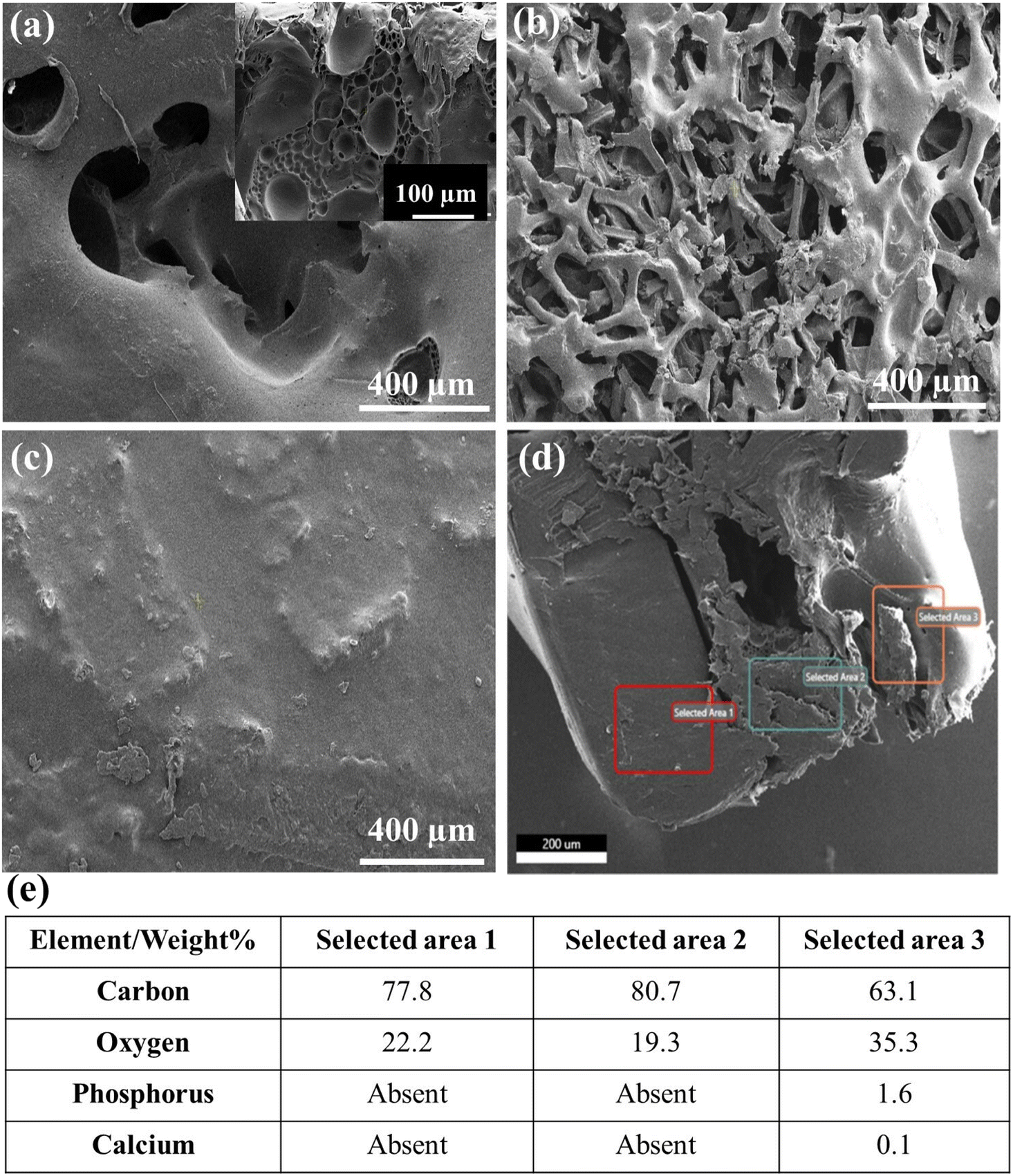 | ||
| Fig. 2 SEM and EDAX data showing the morphologies of various layers and compositions. The morphology of separate layers G1 (a), G2 (b), and G3 (c) are shown in the figure. Image (d) shows a cross-section view of the prepared trilayered scaffold. The EDAX data represented in (e) show the composition of each layer as marked inside rectangular boxes (i.e., selected areas 1, 2, and 3 corresponding to G1, G2, and G3, respectively). Ca and P peaks in EDAX of the G3 layer prove the presence of hydroxyl-apatite in the layer mimicking bone. | ||
The morphology of the layers showed smooth and wrinkle-free surfaces of GF branches owing to the polymer coating. In order to achieve the layered structure across the thickness of the GF, the spin coating was followed by vacuum and hot air drying, as discussed in the Experimental section. Although, here, it was used to prepare the PCL, hollow and PCL + HA layers inside GFs, i.e., hydrophobic layers; the process can be optimized for hydrophilic layers as well. The sacrificial layer should be selected with opposite characteristics (hydrophilic (G2) for hydrophobic (G1 and G3) layers and vice versa), which eases the dissolving process, and maintains only opposite layers. The cross-sectional image provided a view of the porous layer sandwiched between the thick PCL layer on one side and the PCL/HA layer on the other side, as shown in Fig. 1(d). It also helped visualize the varied thickness of the fabricated three layers on the GF corresponding to the layers in the periodontium tissues. The tissue consists of 3 types of layers with unique morphology and properties, i.e., the cementum, a periodontal ligament (PDL), and bone. The thicknesses of the G1 and G2 layers mimicking the cementum and PDL, respectively, were also kept under similar dimensions in the range of 20 to 150 μm for cementum and 15 to 30 μm for PDL. The thickness of the bone layer was in the range of a few microns to mm, depending upon tooth thickness; thus the thickness of G3 could be adjusted accordingly.
Further, the energy dispersive X-ray analysis (EDAX) confirmed the elemental composition of the individual layers in the 3D GF scaffold. The fabricated scaffold also showed chemical similarities to the periodontium tissue. Fig. 2(e) represents the EDAX data in a tabulated form for all three regions; in Fig. 2(d), the presence of the elements like phosphorus and calcium along with carbon and oxygen corresponding to the G3 layer confirms the reinforcement of HA granules inside the polymer matrix. Hydroxyapatite (HA) is a calcium phosphate derivative that induces osteogenesis and osseointegration owing to its chemistry similar to that of apatite found in the human bone. EDAX data corresponding to G1 and G2 only contained carbon and oxygen peaks owing to the carbonic nature of both, the GF and polymer.
Further, in order to perform a qualitative analysis of the distinct layers in the fabricated 3D scaffolds, Raman spectroscopy was used and the results are shown in Fig. 3. The Raman spectrum of pristine GF shows the characteristic peaks at 1586 cm−1 and 2729 cm−1, indicating the G band and 2D group, respectively.21–23 The D band intensity ratio to the G band gives the defects in the GF.20 The absence of the D band at the Raman shift at 1350 cm−1 indicates that the GF used is mainly defect-free and of high quality. The number of layers present in the GF can be predictable by the shape, intensity, and location of the G and 2D bands. The high Raman intensity for the G band in contrast to the 2D group is representative of multi-layered graphene. The intensity ratio for the 2D band to the G band (I2D/IG) < 1 (∼0.5 in this case) also signifies multiple layers of graphene sheets.20 PCL shows a characteristic peak at 2917 cm−1 for the CH2 group.24,25 The G1 layer graph contains additional G and 2D peaks for graphene along with PCL-associated peaks.20 The presence of a distinctive peak at 961 cm−1 owing to the symmetric stretching of P–O bonds (PO4 absorption) confirms the HA reinforcement in the G3 layer. The intensity of the Raman peaks is directly proportional to the amount of the respective material in the layers. As the G2 layer was sandwiched between G1 and G3 layers, the confocal Raman data cannot be achieved for the same.
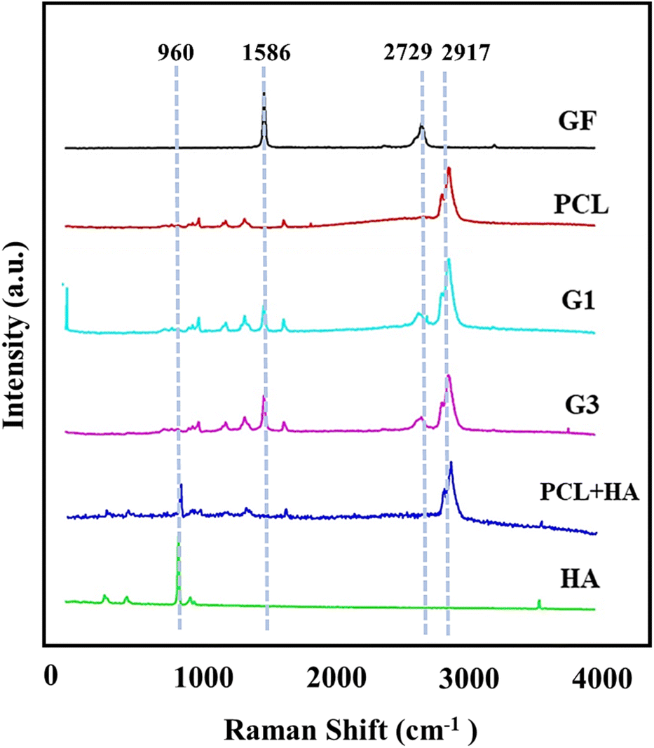 | ||
| Fig. 3 Confocal Raman data for various components on the scaffolds proving their presence in the G1 and G3 layers. | ||
Porosities of the distinct layers in the scaffolds were assessed using the micro-CT images, the representative images of all three layers are shown in Fig. 4(a), (b), and (c) corresponding to G1, G2, and G3 layers, respectively. A total of 510 image frames with interspacing of 22 nm were taken across the cross-section to demonstrate the porosities of different layers. The ImageJ analysis determined the average porosity of each layer, namely G1, G2, and G3, as 13.48%, 50.98%, and 7.98%, respectively. Fig. 4(d) shows the cross-sectional porosity of the scaffold, representing the gradient of the differential porosity. By adjusting the threshold level to B&W, the area occupied by HA granules was also calculated, and it was found to be approximately 4%, i.e., the initial amount of reinforcement. Thus, the HA concentration was in accordance with the reinforcement concentration. In comparison to the existing reports on GF scaffolds for various cell types, the porosity of the fabricated GF scaffolds for the periodontium tissue is expected to allow optimum transport of nutrients and waste elimination. The G2 layer showed uniformly distributed and interconnected porosity with average diameters of 300 ± 29 μm. The large pore size in GF also helps in maintaining the characteristic phenotype of chondrocytes in accordance with previous studies showing the scaffold pore sizes ranging between 250 and 500 μm tend to enhance the proliferation and production of components of the extracellular matrix.26 Fig. S2 in the ESI† shows the 3D porosity Video obtained via the micro-CT analysis.
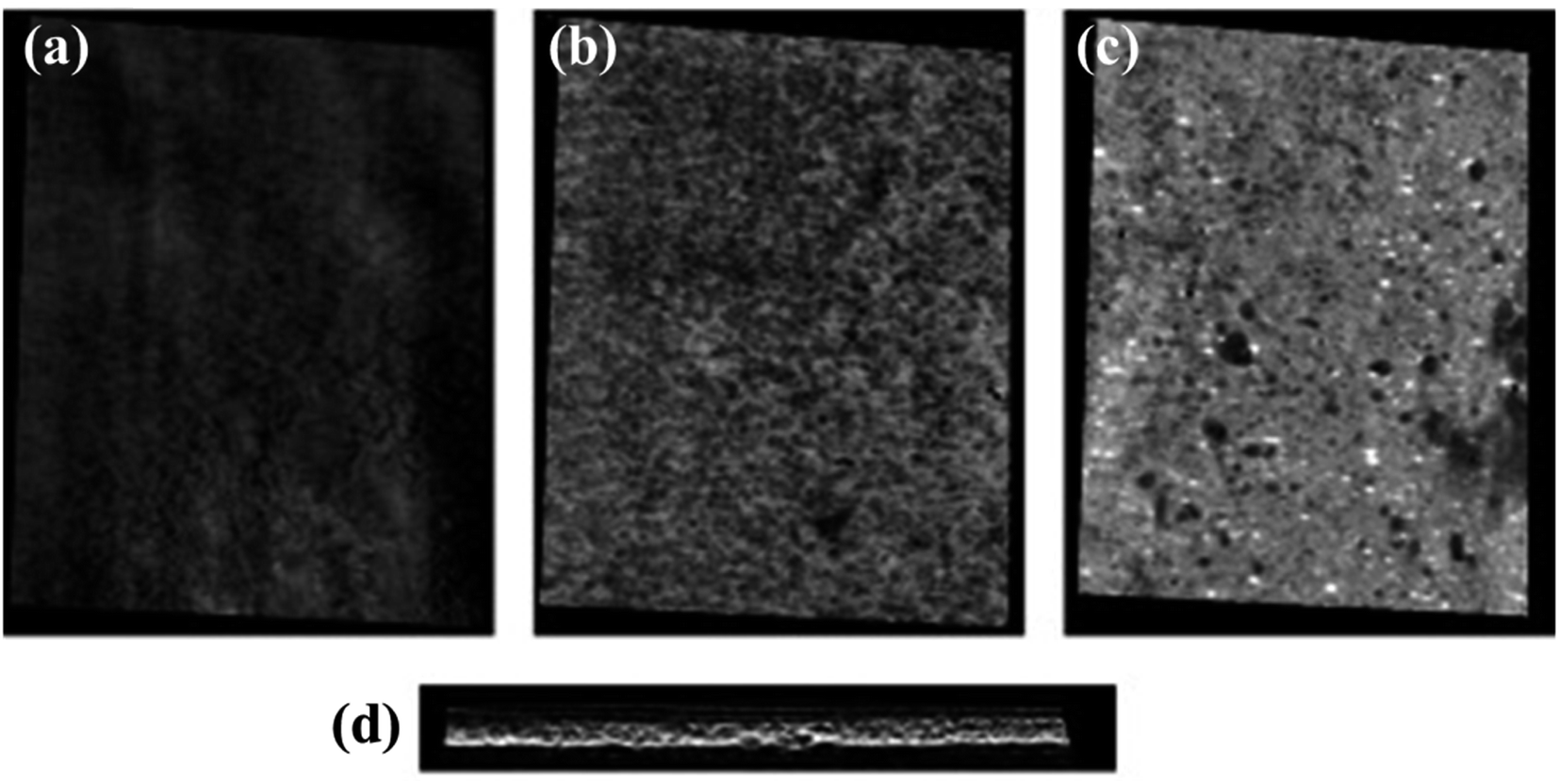 | ||
| Fig. 4 Micro-CT data showing the porosity of various layers in the scaffold. Porosities of G1, G2, and G3 are shown in (a), (b), and (c), respectively. Image (d) shows the cross-sectional porosity of the trilayered scaffold. | ||
3.2. Nano-indentation
Mechanical behavior and deformation mechanisms of the fabricated scaffolds were assessed by nanoindentation test and tensile stress–strain characteristics. All three layers, namely, G1, G2, and G3, were fabricated in order to possess distinct mechanical behavior in accordance with their native functions and structural role. During the nanoindentation test, owing to the very fragile structure, the native graphene foam could not bear any load, thus PCL coating was pre-formed, which significantly increased the load-bearing capacity and handling ability. The nanoindentation test was performed on both branches and nodes in the layers.The load-displacement curve shown in Fig. 5(a) depicts the characteristic load vs. depth plots for the components of the scaffold. Multiple indentation tests were performed on different areas of the samples and the properties were tabulated. The maximum load applied to the branches of the test samples was 100 μN. The table presented in Fig. 5(b) shows the mean values for hardness and Young's modulus of elasticity. The representative optical image of a typical nanoindentation test location is included in Fig. S1 in the ESI.† The deformation occurs due to both, indentation and bending at the branch-node junctions. But the degree and type of reinforcement are significant in the strengthening of the GF matrix. In comparison to the other two layers, in the middle layer G2 bending effect dominates over deformation owing to the highest porosity and least concentration of PCL reinforcement. The G3 layer shows the highest modulus (2.59 ± 0.33 GPa), due to the presence of HA granules (fillers) in the PCL matrix. The lowest porosity helped maintain the structural integrity up to the maximum depth while loading the application in the case of the G3 layer. Here, the deformation mechanism follows a mixed process consisting mainly of branch bending with an increase in load up to 450 nm depth. Furthermore, a substantial increase in the slope switches the deformation mechanism from bending to the indentation in the foam wall. The presence of HA granules in the walls causes the structure to bear extra load. The PCL fills the microvoids and microcracks present in the native graphene foam to provide increased resistance to elastic and plastic deformation.8
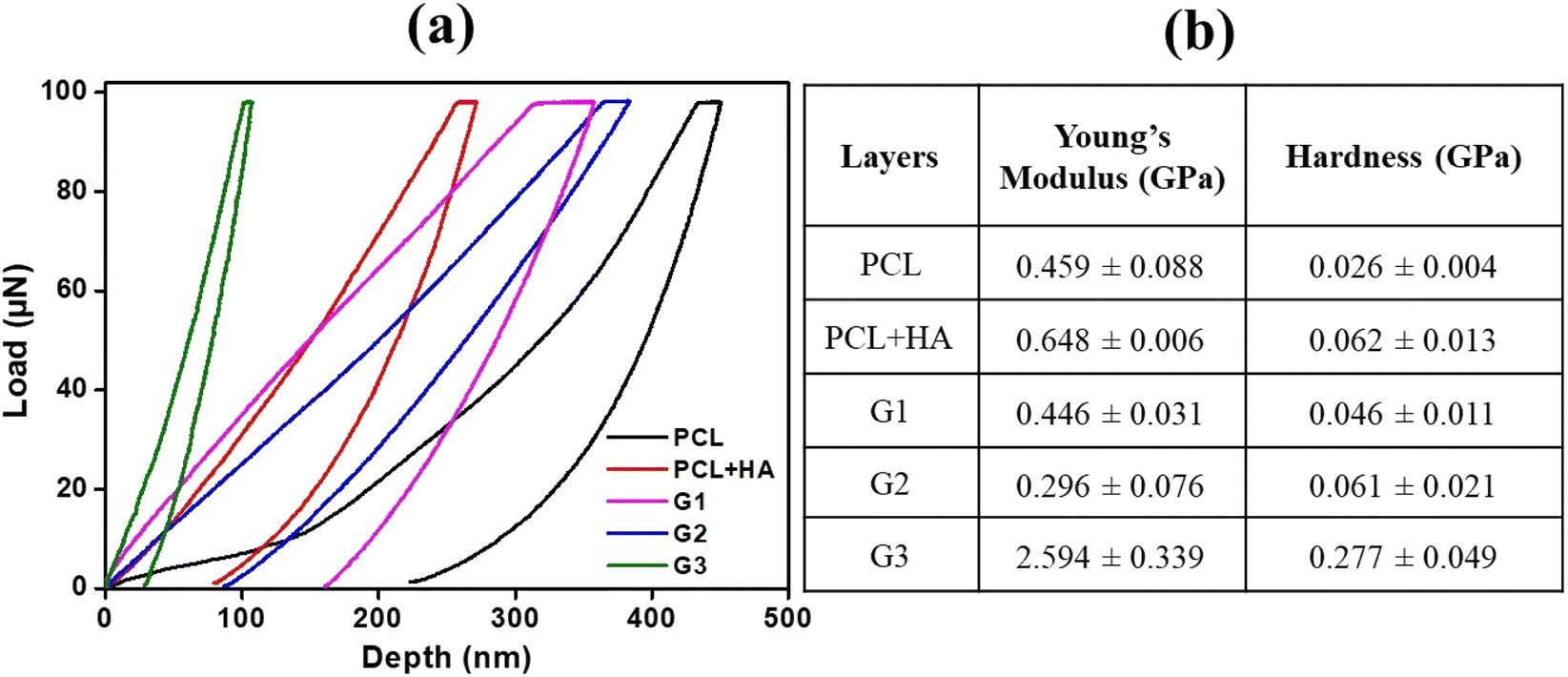 | ||
| Fig. 5 (a) Characteristic load vs. displacement plots obtained from nanoindentation on different surfaces. (b) The table includes Young's modulus and hardness values for the samples. | ||
3.3. Tensile strength
Tensile tests were performed to evaluate the mechanical properties in tension for all the individual layers and the complete 3D scaffold with 3 distinct layers. Fig. 6(a) shows the samples post tensile tests, while Fig. 6(b) represents Young's modulus and ultimate tensile strength of the samples. However, the native GF not being able to be clamped on tensile fixtures could only undergo tensile testing after PCL reinforcement. The PCL reinforcement with macroporosities (i.e., the G0 layer) caused a multifold increase in the elastic modulus (ES) (kPa to MPa). More precisely, the final middle layer of the scaffold individually showed an elastic modulus of 0.159 GPa and ultimate tensile strength (UTS) of 4.299 GPa. Contrary to the inherent brittle characteristic of graphene, it showed ductility with necking prior to fracture due to the high tensile behavior of the polymer matrix. The graphene foams usually fail at strains ≈8.5%,8 whereas in our case PCL increased it up to ≈90%, as shown in Fig. 7(a), a dramatic increment of about 1000%. Though it is noteworthy that the strength of the composite (G0) is lower than PCL alone as the load-bearing ability decreases due to the pre-existing cracks and discontinuous graphene sheet arrangement in GF. The most common feature among all the GF composites was found to be the presence of valleys before failure, as while necking the GF-polymer composite branches undergo twists and bend to align towards the direction of load application followed by the failure of individual low-strength branches, as shown in fractographs for each layer (Fig. 7(b)–(f)) corresponding to the valleys in the stress–strain curves. Yet, the final breakage and modulus of the individual layer correspond to a similar composite. The values for the G1 and G3 layers are 4.299 GPa and 4.439 GPa for UTS, respectively. The strength of the final scaffold lies between its component structures as all the constituents imparted their distinct characteristics to the GF matrix.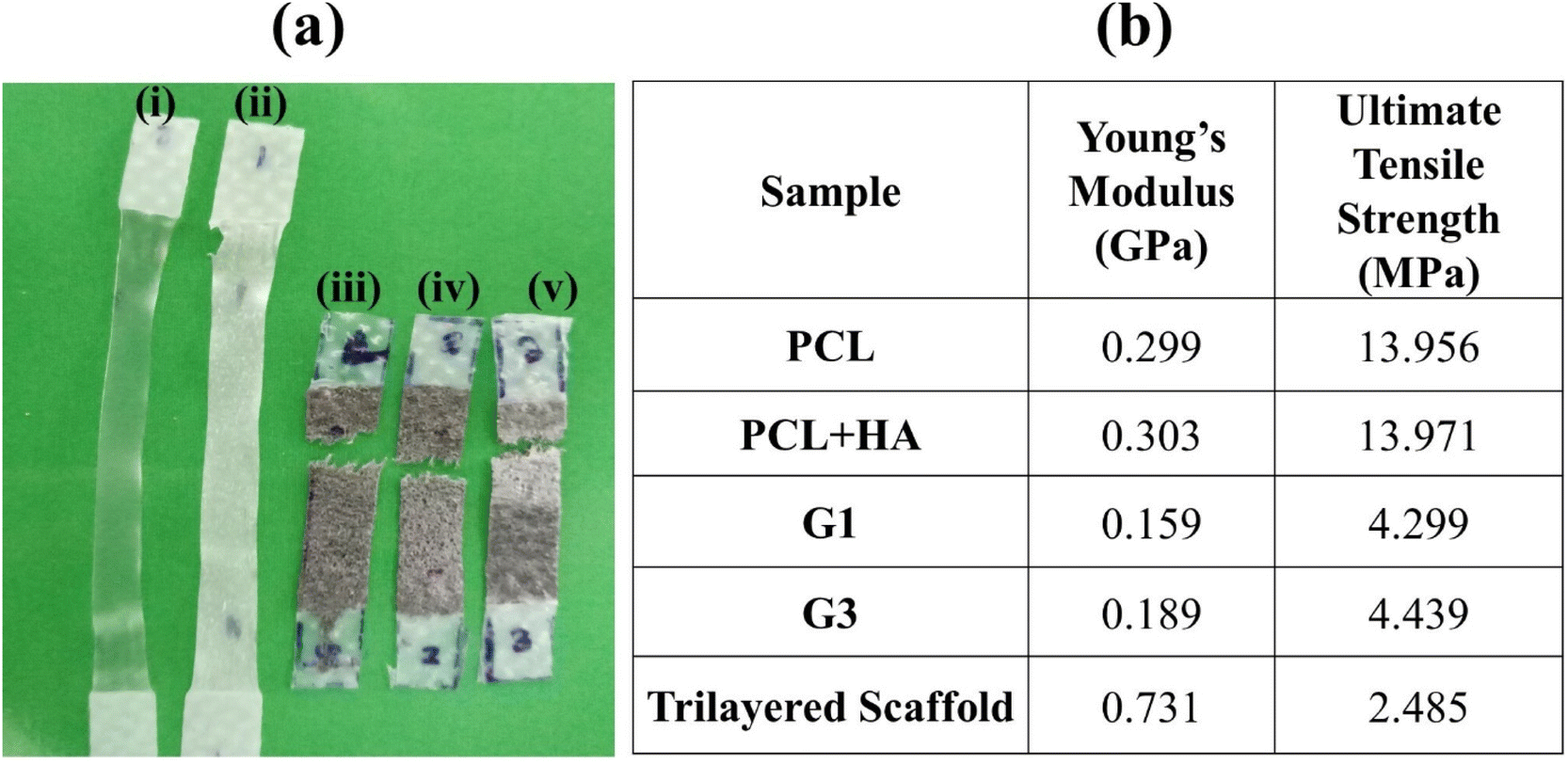 | ||
| Fig. 6 (a) The samples post tensile testing. (b) Table showing Young's modulus and the ultimate tensile strength for the tested samples. | ||
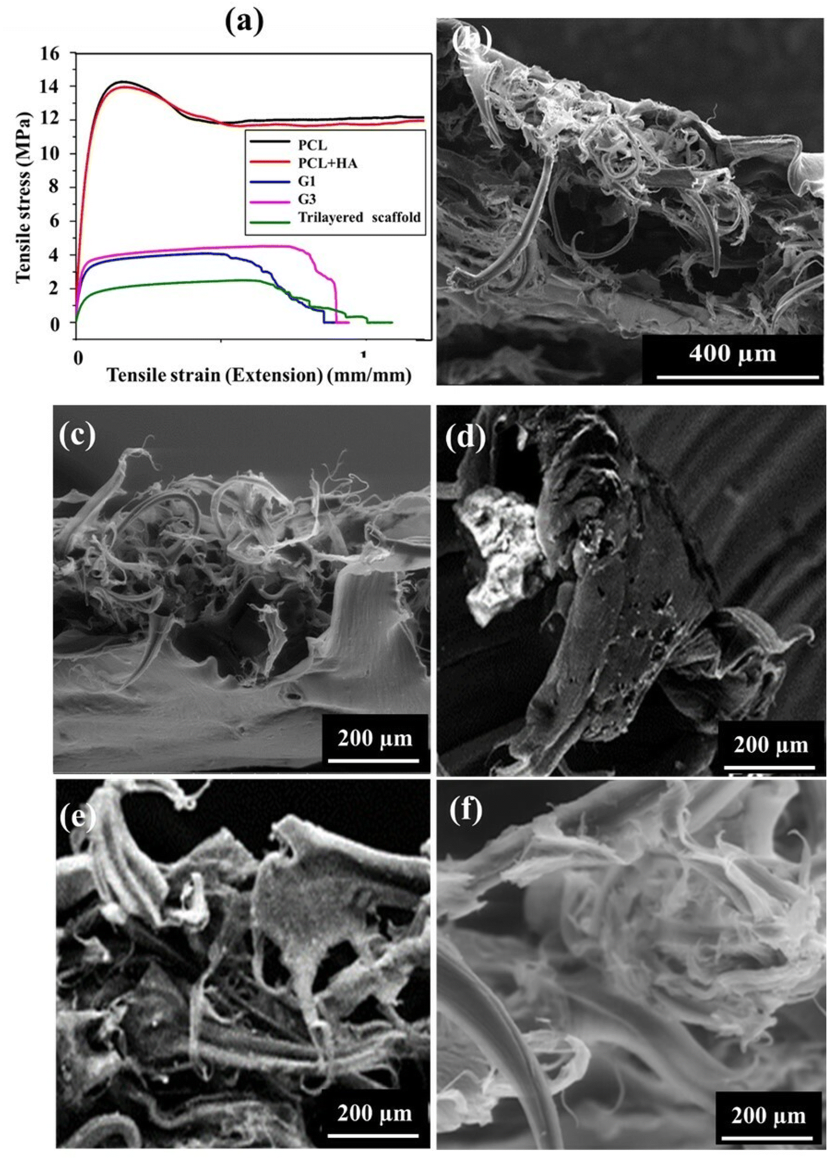 | ||
| Fig. 7 (a) Characteristic stress–strain graphs for all the samples. The SEM images show fracture surfaces for trilayered scaffold (b), PCL (c), PCL + HA (d), G1 layer (e), and G3 layer (f). | ||
The fractography depicts the reinforcing effect of PCL in the otherwise brittle matrix of GF, as individual bridges under tension, strained post breakage. The polymer-reinforced GF branches showed substantial elongation prior to fracture owing to excellent bonding between PCL and GF along with the PCL bridges. The failure points revealed that the cracks tend to cause further delamination and flaking of the PCL layer present on the GF foam.27 Though delamination is quite low owing to the excellent bonding of GF and PCL. The reinforcement of the HA particles inside.
PCL further increases the strength of the composite by preventing crack propagation. The presence of the HA particles hinders the slippage of the polymer molecules surrounding them by restricting the mobility and deformability of the matrix. Thus, the G3 layer mimicking the alveolar bone of teeth showed the highest modulus corresponding to the native dental mechanical stability.28
3.4. Cell culture
In order to assess the biocompatibility of individual layers inside the scaffold, cell adhesion and proliferation were studied. The live and dead cell staining was performed for cells present in the distinct layers using calcein AM and PI dye. Calcein AM can hydrolysis inside the cell and produce green fluorescence in live cells, while the PI dye could stain the nuclei of the dead cells and produce red fluorescence.29–32All the layers showed high cell compatibility, as the cells were able to diffuse through the scaffold due to the presence of microporosities in the GF, as shown in Fig. 4 and 7. Fig. 8(a), (e), and (i) show the bright field images of MG63 cultured cells on top of the G1, G2, and G3 layers. Fig. 8(b), (f), and (j) show live and healthy cell imaging on the G1, G2, and G3 surfaces, which also confirmed that the surface did not show toxicity. Fig. 8(c), (g), and (k) show the imaging of the dead cells, where most of the surface did not show any dead cells except a few dead cells on the G1 surface. The dead cells might be due to slight differences in oxygen and nutrient transport. Fig. 8(d), (h), and (l) show the merged images of live and dead cells, which also confirmed that most of the cells were alive on all the surfaces (G1, G2, and G3) that was confirmed from green to yellowish-green color. The high specific surface area of 3D-GFs facilitated better interfacing for cell attachment and proliferation. The porous structure ensured the efficient mass transport of oxygen supply with nutrients via media. Although, here, the MG63 cells (human osteosarcoma) were used as the model cells due to the reinforcement of the HA particles and its expected applicability for dental implants; the development of the layered structure inside the GF matrix provides the freedom to employ such scaffolds for different cell types. The ease of tunability for the polymer selection for preparing different layers and reinforcing the polymers or GF surface with various micro/nanoparticles/drugs/growth factors/chemicals offers great scope for further use of such scaffolds. The ESI† shows the cell adhesion and compatibility of similar scaffolds for liver cells (Huh7) and neurons (N2a) (ESI Fig. S3 and S4,† respectively).
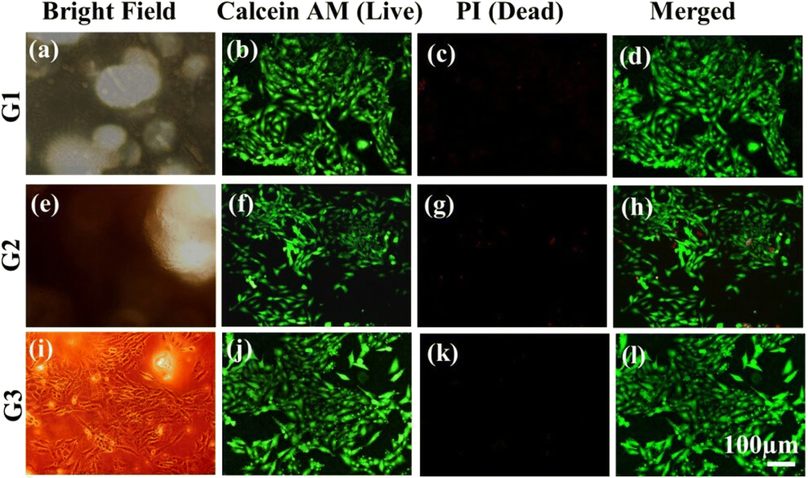 | ||
| Fig. 8 Cell staining performed on scaffolds, the images depict the live and dead staining for MG63 cells in all 3 distinct layers; G1 layer (a), (b), (c), and (d), G2 layer (e), (f), (g), and (h) and G3 layer (i), (j), (k), and (l). Calcein AM and PI dyes stain live (green) and dead cells (red), respectively. | ||
In addition, the MTT assay demonstrates that the scaffold not only provides an adherent substrate for cell adhesion but also maintains cell viability (Fig. 9). The viability was found to be similar to that of the control glass substrate. The proliferation rate of the cells was maintained as per the control sample. The presence of HA also might produce higher levels of bio-mineralization.
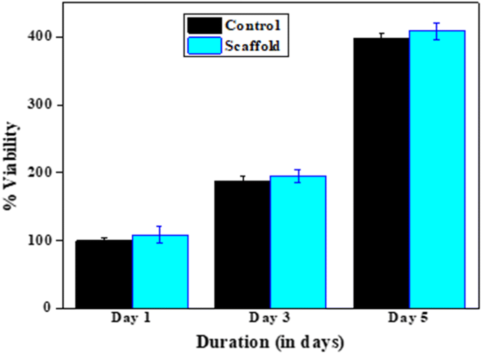 | ||
| Fig. 9 The MTT assay test results showing the viability of MG63 cells on the fabricated scaffolds post 1, 3, and 5 days of incubation. | ||
4. Discussion
A functionally-gradient polymeric scaffold with three phases with mechanical properties similar to those of native tissues was developed. Earlier studies had adopted the approach of multilayered and multiphasic scaffolds made up of a single polymer or multiple types of polymers with spatial reinforcement of bioactive molecules or factors. Although staggeringly multiple bio-material sheets are convenient for cell seeding/culture, the possibility of potential de-lamination of multiple layers is of major concern.It is a foregone conclusion that in situ tissue regeneration is predominantly governed by biophysical and biochemical cues induced by scaffolds/implants, which facilitates tissue regeneration by modulating the extracellular microenvironment or by driving cellular reprogramming.33,34 Considerable developments have been made to provide different types of microarchitectures for the physical organization of regenerated tissue along with supporting cell-scaffold/implant communications. Tissue engineering is a biomedical engineering discipline where cells, scaffolds, and signaling factors form a triad called Tissue Engineered Construct (TEC), a revolutionary concept. A landmark study by Engel et al.35 demonstrated the significance of the mechanical property and shape of the scaffold in determining the type of tissue regenerated. The concept of tissue engineering endorsed the observation of Engel et al. and stressed the need for an optimal mechanical environment. A word of caution is that this optimal mechanical environment varies from tissue to tissue and between two tissues and should be a gradual transition. Hence, it is challenging to develop a scaffold that would provide all the aforementioned requirements and it is even more complicated between hard and soft tissue.
To develop such a scaffold, we chose a tooth-supporting structure (periodontium), consisting of microscopic cementum, a hard tissue on the root surface, bone, and another hard tissue away from the root. The two hard tissues are bridged by multi-directional fiber bundles, which were anchored into the hard structures, enabling the tooth to withstand the huge biting force. With two hard and single fibrous tissue, there is great variability in mechanical properties, which makes it an ideal experimental model to develop a tri-layer scaffold. The requirement of the scaffold for such a complex structure is three phases scaffold with different mechanical properties, with porosity in the center scaffold for nutrient exchange as well for the growth of fibers that can stretch into an adjacent scaffold for anchorage. For the same reasons, all these phases need to be fused so there is no separation, but it should be communicable. Since it must be site-specific, it should be possible to trim it for adaptation and must be thin and flexible.
As per the histology of periodontium, the center stage should have fibroblasts with high proliferative potential so that fibers can be synthesized and extended on either side, on which hard tissues can be deposited to anchor fibers. Our first choice for the centre scaffold was graphene foam because carbon-based scaffolds are stiff and resist compressive forces from surrounding tissues, and in our case, we felt it would be beneficial to withstand masticatory forces in clinical situations. According to Safina et al.36 graphene presents low cytotoxicity to fibroblasts and augments their growth and bioactivity. The graphene foam maintained pores, which facilitated cell migration and fiber polarization. Graphene with exceptional mechanical strength, high electrical conductivity, large surface area, easy functionalization, and biocompatibility has promising prospects in upcoming tissue engineering applications.37 The 3D organization of graphene in the graphene foam further biomimicking the tissue components and architectures, helping in the development of organized and physiologically-functionalized regenerated tissue; particularly, bone-ligament complexes. To our knowledge, this is the first time a scaffold has been designed based on these factors. For the cementum surface, we used PCL, although its modulus is lower than that of the hard tissue, but has facilitated stem cell differentiation into cementoblasts on the hyaline layer with enamel matrix proteins. As such, polycaprolactone with a low modulus of elasticity may be a proper surface for homing cells to differentiate. On the other side of the graphene foam (side facing the bone), the surface was coated with hydroxyapatite (a natural bone mineral) with a modulus close to that of cortical bone and its modulus of elasticity.
Both nanofibers and 3D printed scaffolds have earlier highlighted topological cues at the tissue interface affecting the cell orientation and delivery of various drugs, and biomolecules, i.e., antibiotics and cell growth factors.38,39 Unfortunately, the poor mechanical properties of nanofibers and delamination of distinct layers in multilayered structures raise the issue of collapse leading to tissue disintegration. The 3D printed scaffold may however be intact, but the construction of a seamless scaffold with multi-shape and size porosity to assimilate multilayer regeneration is tedious work. Moreover, the technique possesses some inherent limitations regarding the materials and further functionalization. Thus, there is a need for improvised bioactive multilayered scaffolds to support tissue regeneration and maintain structural integrity and systemic organization. The presently developed scaffold satisfies most of the requirements.
Technically, the concentration of the polymer solution and duration of spin coating followed by curing are the factors to be tuned for 3D GF scaffold preparation. There exists a difference in the dimensions of collagenous fibers in the cementum and bone-associated PDL bundles (respectively, 3- to 10 μm and 10- to 20 μm), it becomes more challenging, and our future endeavour would be to fine-tune the scaffold. In conclusion, the easy reinforcement inside the same GF framework helps develop a seamless scaffold having pore/channel sizes specific to the targeted regions such as periodontium, which can be extended to other complex structures in the human body.
5. Conclusion
This study demonstrates the development of a 3D GF-based trilayered scaffold promoting triphasic tissue regeneration. The scaffold supports the compartmentalization of hard and soft tissues with structural flexibility. The GF matrix also withstands heavy biomechanical forces to maintain anchorage among different layers of the tissue. The layered reinforcement of various extracellular materials and growth factors/drugs in scaffolds facilitates functional restoration in hierarchical architectures. Although the present study involves the reinforcement of hydrophilic polymer between hydrophobic polymers, the process can be applied to sandwiching hydrophobic polymers between hydrophilic polymers. The scaffolds also offer a great degree of functionalization and modification in terms of chemical, mechanical and biological properties. Therefore, owing to its remarkable mechanical and biological properties, this 3D GF scaffold is highly suitable for multiple tissue engineering applications.Conflicts of interest
The authors declare no conflicts of interest among themselves.Acknowledgements
We acknowledge the DBT/Wellcome Trust India Alliance grant number IA/E/16/1/503062 awarded to Dr Tuhin Subhra Santra and IITM Institute postdoc funding (ED19IPF03) for supporting this research.References
- M. I. Katsnelson, Mater. Today, 2007, 10, 20–27 CrossRef CAS.
- C. Chung, Y. K. Kim, D. Shin, S. R. Ryoo, B. H. Hong and D. H. Min, Acc. Chem. Res., 2013, 46, 2211–2224 CrossRef CAS PubMed.
- O. Akhavan, J. Mater. Chem. B, 2016, 4, 3169–3190 RSC.
- S. Kumar and K. Chatterjee, ACS Appl. Mater. Interfaces, 2016, 8, 26431–26457 CrossRef CAS PubMed.
- H. P. Zhang, X. G. Luo, X. Y. Lin, X. Lu and Y. Tang, Appl. Surf. Sci., 2016, 360, 715–721 CrossRef CAS.
- D. Pan, C. Wang, T. C. Wang and Y. Yao, ACS Nano, 2017, 11, 8988–8997 CrossRef CAS PubMed.
- K. M. Yocham, C. Scott, K. Fujimoto, R. Brown, E. Tanasse, J. T. Oxford, T. J. Lujan and D. Estrada, Adv. Eng. Mater., 2018, 20, 1–9 CrossRef PubMed.
- A. Nieto, R. Dua, C. Zhang, B. Boesl, S. Ramaswamy and A. Agarwal, Adv. Funct. Mater., 2015, 25, 3916–3924 CrossRef CAS.
- N. Li, Q. Zhang, S. Gao, Q. Song, R. Huang, L. Wang, L. Liu, J. Dai, M. Tang and G. Cheng, Sci. Rep., 2013, 3, 1604 CrossRef PubMed.
- J. K. Wang, G. M. Xiong, M. Zhu, B. Özyilmaz, A. H. Castro Neto, N. S. Tan and C. Choong, ACS Appl. Mater. Interfaces, 2015, 7, 8275–8283 CrossRef CAS PubMed.
- J. K. Wang, G. M. Xiong, M. Zhu, B. Özyilmaz, A. H. Castro Neto, N. S. Tan and C. Choong, ACS Appl. Mater. Interfaces, 2015, 7, 8275–8283 CrossRef CAS PubMed.
- B. Holmes, X. Fang, A. Zarate, M. Keidar and L. G. Zhang, Carbon, 2016, 97, 1–13 CrossRef CAS.
- A. Idowu, B. Boesl and A. Agarwal, Carbon, 2018, 135, 52–71 CrossRef CAS.
- Q. Song, Z. Jiang, N. Li, P. Liu, L. Liu, M. Tang and G. Cheng, Biomaterials, 2014, 35, 6930–6940 CrossRef CAS PubMed.
- L. Feng, Y. Hao, M. Zhu, Y. Zhai, L. Yang, Y. Liu and G. Cheng, ACS Biomater. Sci. Eng., 2019, 5, 5295–5304 CrossRef CAS PubMed.
- Y. Li, X. Zhang, C. Dai, Y. Yin, L. Gong, W. Pan, R. Huang, Y. Bu, X. Liao, K. Guo and F. Gao, ACS Biomater. Sci. Eng., 2020, 6, 3015–3025 CrossRef CAS PubMed.
- N. Bahremandi Tolou, H. Salimijazi, M. Kharaziha, G. Faggio, R. Chierchia and N. Lisi, Mater. Sci. Eng., C, 2021, 126, 112110 CrossRef CAS PubMed.
- M. G. Yeo and G. H. Kim, Chem. Mater., 2012, 24, 903–913 CrossRef CAS.
- M. Türk and A. M. Deliormanli, Mater. Res. Express, 2018, 5, 045406 CrossRef.
- A. Nieto, B. Boesl and A. Agarwal, Carbon, 2015, 85, 299–308 CrossRef CAS.
- A. C. Ferrari, J. C. Meyer, V. Scardaci, C. Casiraghi, M. Lazzeri, F. Mauri, S. Piscanec, D. Jiang, K. S. Novoselov, S. Roth and A. K. Geim, Phys. Rev. Lett., 2006, 97, 187401 CrossRef CAS PubMed.
- D. Graf, F. Molitor, K. Ensslin, C. Stampfer, A. Jungen, C. Hierold and L. Wirtz, Nano Lett., 2007, 7, 238–242 CrossRef CAS PubMed.
- Y. H. Kwon, S. Kumar, J. Bae and Y. Seo, Nanotechnology, 2018, 29, 195404 CrossRef PubMed.
- A. Gallos, G. Paës, D. Legland, F. Allais and J. Beaugrand, Composites, Part A, 2017, 94, 32–40 CrossRef CAS.
- A. Kotzianova, J. Rebicek, P. Mojzes, M. Pokorny, J. Palacky, J. Hrbac and V. Velebny, Polymer, 2014, 55, 5036–5042 CrossRef CAS.
- Q. L. Loh, C. Choong, D. Oxon, M. Hons and C. Mimmm, Tissue Eng., Part B, 2013, 19, 485–502 CrossRef CAS PubMed.
- P. Nautiyal, M. Mujawar, B. Boesl and A. Agarwal, Carbon, 2018, 137, 502–510 CrossRef CAS.
- B. Wu, Y. Fu, H. Shi, B. Yan, R. Lu, S. Ma and B. Markert, Biomed. Eng., 2018, 17, 1–11 Search PubMed.
- T. S. Santra, C. W. Chen, H. Y. Chang and F. G. Tseng, RSC Adv., 2016, 6, 10979–10986 RSC.
- P. Shinde, S. Kar, L. Mohan, H.-Y. Chang, F.-G. Tseng, M. Nagai and T. S. Santra, ACS Biomater. Sci. Eng., 2020, 6, 5645–5652 CrossRef CAS PubMed.
- P. Gupta, S. Kar, A. Kumar, F. G. Tseng, S. Pradhan, P. S. Mahapatra and T. S. Santra, Analyst, 2021, 146, 4756–4766 RSC.
- L. Mohan, S. Kar, M. Nagai and T. Subhra, Mater. Chem. Phys., 2021, 267, 124604 CrossRef CAS PubMed.
- M. P. Lutolf, P. M. Gilbert and H. M. Blau, Nature, 2009, 462, 433–441 CrossRef CAS PubMed.
- Z. Hao, Z. Song, J. Huang, K. Huang, A. Panetta, Z. Gu and J. Wu, Biomater. Sci., 2017, 5, 1382–1392 RSC.
- E. Engel, A. Michiardi, M. Navarro, D. Lacroix and J. A. Planell, Trends Biotechnol., 2008, 26, 39–47 CrossRef CAS PubMed.
- I. Safina, S. E. Bourdo, K. M. Algazali, G. Kannarpady, F. Watanabe, K. B. Vang and A. S. Biris, PLoS One, 2020, 15, 1–16 Search PubMed.
- P. Gupta, A. Agrawal, K. Murali, R. Varshney, S. Beniwal, S. Manhas, P. Roy and D. Lahiri, Mater. Sci. Eng., C, 2019, 97, 539–551 CrossRef CAS PubMed.
- C. H. Park, K. H. Kim, H. F. Rios, Y. M. Lee, W. V. Giannobile and Y. J. Seol, J. Dent. Res., 2014, 93, 1304–1312 CrossRef CAS PubMed.
- C. H. Lee, J. Hajibandeh, T. Suzuki, A. Fan, P. Shang and J. J. Mao, Tissue Eng., Part A, 2014, 20, 1342–1351 CrossRef CAS PubMed.
Footnote |
| † Electronic supplementary information (ESI) available. See DOI: https://doi.org/10.1039/d2ra06018c |
| This journal is © The Royal Society of Chemistry 2023 |