
 Open Access Article
 This Open Access Article is licensed under a Creative Commons Attribution-Non Commercial 3.0 Unported Licence
Preparation of different conjugated polymers characterized by complementary electronic properties from an identical precursor†
Marco
Carlotti
 *abc,
Tommaso
Losi
d,
Francesco
De Boni
e,
Federico Maria
Vivaldi
a,
Esteban
Araya-Hermosilla
b,
Mirko
Prato
e,
Andrea
Pucci
ac,
Mario
Caironi
d and
Virgilio
Mattoli
b
*abc,
Tommaso
Losi
d,
Francesco
De Boni
e,
Federico Maria
Vivaldi
a,
Esteban
Araya-Hermosilla
b,
Mirko
Prato
e,
Andrea
Pucci
ac,
Mario
Caironi
d and
Virgilio
Mattoli
b
aDipartimento di Chimica e Chimica Industriale, University of Pisa, Via G. Moruzzi 13, 56124, Pisa, Italy. E-mail: marco.carlotti@iit.it; marco.carlotti@unipi.it
bCenter for Materials Interfaces, Istituto Italiano di Tecnologia, Viale Rinaldo Piaggio 34, 56025, Pontedera, Italy
cCentro per la Integrazione Della Strumentazione Dell'Università di Pisa (CISUP), University of Pisa, Lungarno Pacinotti 43/44, 56126, Pisa, Italy
dCenter for Nano Science and Technology @PoliMi, Istituto Italiano di Tecnologia, Via R. Rubattino 81, 20134 Milano, Italy
eMaterials Characterization Facility, Istituto Italiano di Tecnologia, Via Morego 30, 16163 Genova, Italy
First published on 7th September 2023
Abstract
The possibility of generating regions with different electronic properties within the same organic semiconductor thin film could offer novel opportunities for designing and fabricating organic electronic devices and circuits. This study introduces a new approach based on a novel type of highly processable polymer precursor that can yield two different conjugated polymers characterized by complementary electronic properties, i.e. promoting electron or hole transport, from the same starting material. In particular, these multipotent precursors comprise functionalized dihydroanthracene units that can offer several functionalization opportunities to improve the solubility or insert specific functionalities. This strategy also allows for the preparation of high-molecular-weight conjugated polymers comprising diethynylanthracene and anthraquinone units without the need for solubilizing side chains. Thin films of the polymer precursor can be used, after solid-state transformations, to prepare single organic layers comprising regions characterized by different chemical nature and electronic properties. Here, we present a detailed characterization of the chemical and electronic properties of the precursor and the obtained conjugated polymers, showing how it is possible to harvest their characteristics for potential applications such as electrochromic surfaces and organic field-effect transistors.
Introduction
There is no doubt that the development of semiconductor technologies in the past century was the turning point in the rise of modern-day electronics and the information revolution. Despite their success in applications such as organic light-emitting diodes (OLEDs) and the expected commercialization of organic solar cells (OPV) and field-effect transistors (OFETs), one can find several use cases for which organic semiconductors did not meet the expectations the scientific community had 50 years ago.1–6 An unparalleled advantage of silicon-based technology over organics consists of the possibility of obtaining, on a single substrate, defined regions characterized by different and complementary electrical properties, thanks to the fine-tuning of the free charge carrier density profile in the semiconductor through doping.7 The possibility of employing complementary logic configurations (CMOS) allows a more efficient design of logic elements, which are faster and more robust, consume less power and have an overall smaller footprint than similar circuits obtained from unipolar materials.8,9The possibility of using complementary schemes is not straightforward with organic semiconductors.10,11 One of the most critical limitations concerns the difficulty in locally confining the doping process.12 This is because, unlike silicon, in these materials, dopant molecules have a tendency to diffuse in the semiconductor, leading to a more homogeneous profile at equilibrium. Furthermore, the number of techniques based on solution processes able to pattern the doping process is quite limited, and often they do not achieve the desired resolution. Therefore, unlike CMOS technology, strategies to promote charge injection in organic devices have to rely on less efficient methods and complex fabrication procedures.13–16 The demonstration of complementary and unipolar behaviour originating from the intrinsic electronic properties of the same thin film is still lacking in the scientific literature. In this sense, two different materials, more fabrication steps, and complex architectures are necessary to design complementary, “CMOS-like”, logic gates.17–20
Aiming at the possibility of patterning the same organic layer with complementary electronic properties, we turned our attention to polymeric precursors for the fabrication of conjugated semiconducting polymers.6 In those cases where the low solubility of the latter can prevent the synthesis of high-molecular-weight materials or compromise the device fabrication processes due to their planar structure and tendency to aggregate via extended π–π interactions, polymeric precursors have often been employed, especially when the addition of side groups that can improve the solubility is not a viable option.6,21–23 A precursor is designed to enhance the solubility of a target material that is then obtained on-demand from the former upon a high-yielding and selective reaction. Several precursor approaches have been designed in the past decades targeting conjugated polymers24–30 (but not limited to them),31–34 with the constant being that one precursor produced one final material.
Here, we describe a novel class of precursors that, unlike the previous cases, can undergo two different final reactions to yield two different conjugated polymers, with markedly different redox properties, from the same starting material. Because of this characteristic, we call them ‘multipotent’. Remarkably, following this approach, it is possible to obtain from the same precursor different organic semiconductors characterized by either a low LUMO (i.e., electron-poor) or a high HOMO (i.e., electron-rich), thus exhibiting complementary electronic properties. In addition, we show that the transformation can be performed in the solid state (e.g., on a thin film), thus allowing the preparation of single organic layers with different chemical nature and electronic characteristics.
Results and discussion
The investigated precursor polymers comprise 9,10-dihydroanthracene units functionalized with substituted propargyl alcohol moieties at the 9 and 10 positions. The presence of the propargyl alcohol moiety not only breaks the conjugation by inserting a more flexible sp3 carbon but also offers several functionalization opportunities (on the triple bond and/or on the hydroxyl group) to insert solubilizing chains or particular functionalities. This solution allows several options to improve the solubility and the overall processability of the precursors and/or impart a specific reactivity. We show the potential of this approach by employing a polymer precursor comprising dihydroanthracene units functionalized with a triisopropylsilyl (TIPS) group on the triple bond and a trimethylsilyl (TMS) group on the hydroxyl group, and connected via a bithiophene linker (AH-P, Fig. 1a), although one can apply the same methodology to other structures (see the ESI†). This polymer was obtained employing a Stille polymerization, resulting in a chain with an average number of repeating units of about 15. Changing the substituents on the triple bond can lengthen the chain (an average of 24 and 56 units were obtained when a phenyl chain or a hexyl chain, respectively, was employed in place of TIPS; see the ESI†). | ||
| Fig. 1 (a) Schemes of the reactions yielding AQ-P and AC-P from the precursor. (b) Energy diagram of the HOMO and LUMO levels of model oligomers of the investigated polymers obtained via DFT (B3LYP-D3BJ/def2-TZVP). (c) Comparison of IR spectra of the conjugated polymers obtained via the precursor route and via direct synthesis. | ||
From this non-conjugated precursor, through a reduction–rearomatization reaction, one can obtain a polymer comprising 9,10-diethynlanthracene units (AC-P, Fig. 1a), characterized by a high-energy HOMO level and a linear conjugation.35,36
Anthracene-based materials have often been proposed for applications in optoelectronics, including OPV devices,37,38 OLEDs,39,40 OFETs41,42 and sensing,43 as they can be particularly useful in those cases for which a medium bandgap is needed.44
Alternatively, by removing the acetylide moiety under retro-Favorskii conditions, it is possible to prepare a polymer bearing anthraquinone units (AQ-P, Fig. 1a), i.e., characterized by a low-energy LUMO level and a cross-conjugated framework.45,46
Direct polymerization of bithiophene with diethynylanthracene (AC-DP) or anthraquinone (AQ-DP), performed under the same conditions employed above, resulted in the formation of oligomers (two to four repetitions) that were insoluble despite a short chain length (see the ESI†). Increasing the duration of the polymerization (or the temperature) resulted in a higher fraction of intractable material. In this sense, the precursor approach presented herein can offer an effective solution to achieve high-molecular-weight conjugated polymers comprising diethynylanthracene and anthraquinone units without the need for solubilizing side chains.
We optimized the reaction conditions so that both the transformation reactions can be performed with high yields and in short times (this is discussed in more detail in the ESI†). In particular, for the reduction–rearomatization, we employed SnCl2 in a methanol solution containing 0.1%vv of concentrated HCl heated to 60 °C (alternatively, a saturated solution of SnCl2 in acetic acid can be employed).35 In this way, we could reduce the extent of the side reactions and obtain quantitative yields in the case of small model molecules consisting of the repetitive unit in the polymers depicted in Fig. 1 substituted with thiophenes at the 2, 6 positions (see the ESI†). Remarkably, just washing with water resulted in the pure product, making this procedure ideal to be applied to polymers. When AH-P was reacted under the same conditions, the colour changed rapidly (within one minute) from faint green to bright red, indicating, as expected, a shorter bandgap for the fully conjugated AC-P polymer. We also observed a shift from green to red in the fluorescence emission; see Fig. SI11.† Because of the insolubility of the product, we characterized the chemical nature of the material through several techniques (13C-ssNMR, XPS, IR, CV, and absorption spectroscopy). Compared to the spectrum of AH-P, the 13C-ssNMR spectrum showed the absence of the signal related to the TMS group or the sp3 carbons present in the precursor at positions 9 and 10 (Fig. SI6†). Particularly remarkable is the similarity between the IR spectra of AC-P and the structurally related oligomer AC-DP (Fig. 1c) obtained by direct polymerization of the monomers. XPS analysis, conducted on AC-P thin films, revealed the presence of only trace amounts of Sn impurities, primarily identified as SnO2. To further assess the structural characteristics of the polymer, we calculated the carbon-to-sulphur (C/S) and silicon-to-sulphur (Si/S) molar ratios by CHNS elemental analysis and XPS, respectively. Sulphur was taken as the reference as the number of sulphur atoms in the polymer units does not change within the described transformation reactions. The choice of combining these techniques arises from the fact that, while the former was not suitable to measure silicon directly, the latter cannot reliably estimate the carbon content because of the presence of the so-called adventitious carbon.47–49 In the case of AC-P, we found the C/S and Si/S ratios to be 21.7 and 1.4, respectively, in good agreement with the theoretical values of 22 and 1. The lower agreement of the ratio obtained from XPS compared to the expected value can be related to the fact that the intensity of the XPS signals is affected by the relative position of the atoms with respect to the surface.50 Bulky groups, such as TIPS, can more easily protrude from the surface, thus increasing the intensity of the Si signal relative to the S signal.
As mentioned above, the same precursor AH-P is treated with a strong base to remove the alkyne fragment and rearrange it to form AQ-P, a material characterized by strikingly different electronic and redox properties. The retro-Favorskii reaction usually requires strong basic systems (such as KOH in toluene), several hours of reaction time, and high temperatures, which often impact the yield.51 In fact, in the particular case of AH-P, we could not achieve complete conversion even after 6 hours. The removal of the TMS groups (e.g., K2CO3 in methanol) allowed the reaction to be completed in less than an hour in a KOH/toluene system. Therefore, to improve the kinetics and reduce the number of steps, we investigated the use of fluoride in this reaction as it can easily remove silicon protecting groups and, under aprotic conditions, can act as a base,52,53 promoting the retro-Favorskii reaction.
Notably, we found that by employing n-butylammonium fluoride (TBAF) as a fluoride source, we could perform the desired reaction at a lower temperature (70 °C), for shorter times (<10 minutes) and with quantitative yields on model molecules.54 As in the case of the reduction–rearomatization, also in this case, washing with water afforded high-purity products.54 When the reaction was performed on the AH-P precursor, the colour changed to brown-red, and the fluorescence disappeared. The resulting material was characterized as in the abovementioned case and identified as the desired AQ-P. The 13C-ssNMR spectrum showed different features this time (Fig. SI6†), with a signal appearing at about 180 ppm, which was not present in the precursor and which we can ascribe to the quinoid carbonyl. The signals of the TIPS and TMS groups were not entirely absent, showing that the transformation did not proceed to completion. This is probably due to the insolubility of the newly formed anthraquinone polymer, which may prevent the reagents from accessing all parts of the polymer. As in the case of the previous polymer, the IR spectrum of AQ-P showed the same peaks and relative intensities as that of AQ-DP (Fig. 1c), despite the former having a much larger molecular weight. The molar ratios of C/S and Si/S (obtained as described earlier) calculated for AQ-P were 11.3 and 0.05, respectively (theoretical values are 11 and 0). While they are in good agreement with the values expected from the polymeric unit, they also indicate the presence of a small amount of unreacted precursor species. However, the molar amount of precursor left after the reaction was less than 0.1% (calculated from the Si signal obtained by XPS). Conversely, when the TMS group on AH-P was changed to a methyl group, which does not degrade under basic conditions, the retro-Favorskii reaction did not proceed, thus preventing the formation of the quinone (see the ESI†).
It is worth mentioning that since TBAF is compatible with many organic solvents, one has many options to find the best suitable conditions, including those for which the precursor does not dissolve (such as ketonic solvents and acetonitrile).54 The latter aspect is particularly appealing to perform the transformation reaction directly on thin films of AH-P as AQ-P would otherwise be too insoluble to be processed. Similarly, thin films of AC-P can also be obtained directly from those of the precursor, since the latter does not dissolve in some of the solvents that one could employ for the necessary reduction–rearomatization reaction, such as methanol or acetic acid in the specific case mentioned here. Both these transformation reactions can be carried out in similar manners to those described earlier, generally immersing the substrates carrying the precursor thin films in the respective Sn(II) or TBAF solution to prepare AC-P or AQ-P. We characterized the morphology of the thin films described above via atomic force microscopy (AFM) and scanning electron microscopy (SEM), as reported in Fig. SI13–SI15.† Upon transformation, the roughness increases (from 4.71 nm for AH-P to 5.32 nm and 8.41 nm for AC-P and AQ-P, respectively), probably because of the more favourable aggregation in the conjugated materials. Some aggregates can be observed on the surface; nonetheless, the films appear continuous, without the formation of holes or evident detachments, an extremely relevant aspect for the implementation of these materials in functional devices.
We then characterized the distinctive optoelectronic features of these materials. The transformations of the precursor, which generate fully conjugated polymers from a non-conjugated one, drastically affect the colour of the material by reducing the bandgap. While films of AH-P appeared as a faint yellow-green colour, AC-P and AQ-P are characterized by deep red and brown colorations, respectively. We report in Fig. 2a the absorption spectra of the thin films. We could estimate the band gaps, Eg, for the polymers to be in the range of 2.0 eV, much shorter than that of the precursor (2.8 eV; theoretical value is 3.0 eV). Aggregation phenomena – enhanced in the thin films by the absence of steric repulsions of the side chains – could, however, shift the absorption to lower energies. For AQ-P, an indication of this can be found in the different absorption spectra obtained for films prepared following an identical procedure but on other substrates (Fig. SI10†), such as polyethylenenaphthalate (PEN) or indium-tin oxide (ITO).
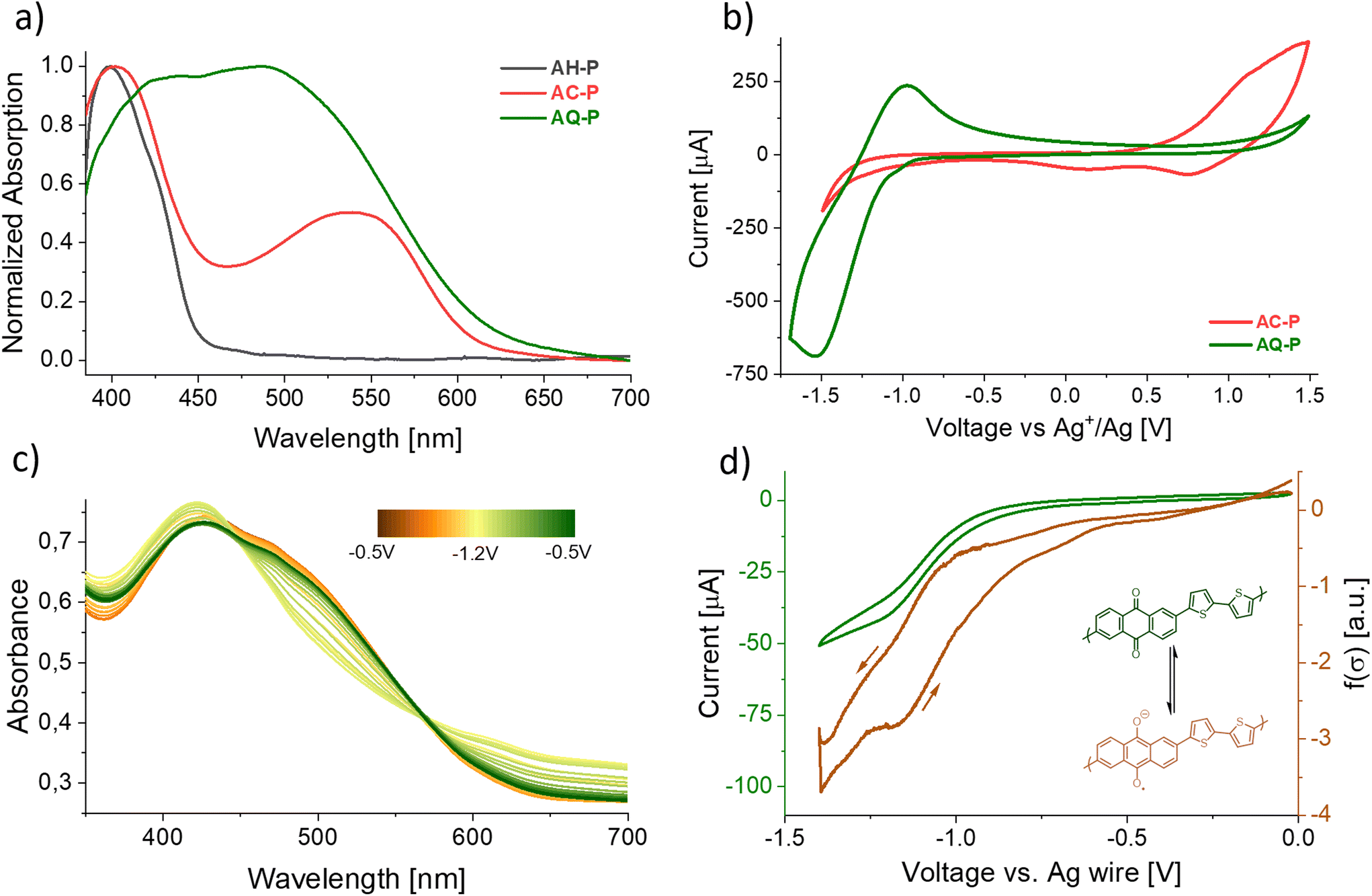 | ||
| Fig. 2 (a) UV-Vis absorption of thin films of AH-P (dark ray), AC-P (red), and AQ-P (green) on ITO. (b) CV scans of the same polymeric films on ITO electrodes in acetonitrile 0.1 M Bu4NPF6 employing an Ag wire immersed in 0.1 M AgNO3 as a reference as described in the ESI.† (c) Change in the absorption profile of an AQ-P film on ITO upon electrochemical reduction. (d) Local conductivity measurement of an AQ-P film upon reduction (see the ESI† for the procedure). | ||
According to DFT calculations performed on model oligomers, AC-P displays a HOMO energy level of about −4.88 eV and a LUMO energy level of −2.74 eV (Eg = 2.14 eV), while AQ-P is characterized by lower HOMO and LUMO levels of −5.65 eV and −3.21 eV (Eg = 2.44 eV), respectively. While these calculations are not meant to be quantitative, this observation relates to the hypothesis that AQ-P is more prone to reduction whilst AC-P is more readily oxidized than their respective counterparts.
Cyclic voltammetry on thin films (CV, Fig. 2b and SI18–SI23†) indeed showed that a reversible electrochemical reduction occurs more readily in the case of the former (E1/2 = −1.18 V vs. Ag/AgNO3 0.1 M in acetonitrile), while oxidation occurs in the case of the latter. The peak observed for a material was not present in the voltammogram of the other and vice versa. In contrast to the highly reversible reduction of AQ-P, the oxidation of AC-P showed signs of degradation when employing acetonitrile as a solvent (Fig. SI19 and SI20†). This observation aligns with other reports of CV performed on 9,10-substituted anthracene materials.55–57 No peaks were observed in the case of the precursor (Fig. SI21†). The results of the CV, together with the observed optical properties, show evidence that, indeed, AQ-P and AC-P possess an energy diagram similar to that predicted by the calculations, with the former being more easily reduced and the latter more easily oxidized. A peculiar feature of anthraquinoid systems is that, upon reduction, the conjugation path changes from cross-conjugation to linear-conjugation, affecting the delocalization of the orbitals, lowering the bandgap and improving the overall conductivity.58 We observed this behaviour directly in the case of the AQ-P films that showed non-zero conductivity upon reduction (Fig. 2d). The position of the HOMO levels in the thin films versus the vacuum level, also known as the ionization energy, was experimentally estimated by means of UPS analysis to be −5.38 eV and −5.80 eV for AC-P and AQ-P, respectively, according to the method detailed in the ESI.†
After having demonstrated the successful conversion of precursors into conjugated polymers with markedly different frontier energy orbitals, we showed the potential of these materials and the methodologies described for the fabrication of different proto-thin film devices, namely, electrochromic layers and OFETs, which could highlight the different behaviours of materials characterized by complementary electronic properties. As introduced previously, a change in the redox state of both the conjugated polymers resulted in a colour change. In particular, brown films of AQ-P became green upon reduction, and red AC-P films became blue upon oxidation. In Fig. 2c, we report the absorption properties of a film of AQ-P at different voltages. Upon reduction, it is possible to observe the absorbance decreasing in the region around 500 nm and, simultaneously, increasing for the peak centred at 415 nm and at longer wavelengths. As depicted, the process appears not fully reversible, as the last scan (green line) is not entirely superimposable to the first (orange line). This variation, however, could result from a reorganization of the polymer molecules in the film after the charged state creates a strong coulombic repulsion between chains. We did not record a similar collection of spectra in the case of AC-P oxidation as the film falls apart upon the prolonged oxidation time required for the measurement.
A fundamental aspect of the approach we developed lies in the possibility of generating regions of different materials (and thus complementary electronic properties) on the same organic layer. As mentioned earlier, this can be obtained, for instance, by employing TBAF in methylisobutylketone (MIBK) or a saturated SnCl2 acetic acid solution and delivering them on the precursor layer using soaked soft rubber stamps or capillaries while heating the substrate.
We employed this protocol to show the possible fabrication of a multi-zone multi-colour single-layer electrochromic surface in which specific domains of AQ-P and AC-P were obtained on the same film of AH-P spin-coated on ITO (Fig. 3). To do this, we placed the ITO electrode in a CV cell and cycled the applied potential between −1.5 V and +1 V (starting from 0 V). We first observed a colour change in the AQ-P region (due to the reduction of the AQ centres, as expected from the CV data), which reverted to the original brown colour on increasing the voltage, and then a colour change (to blue) in the AC-P region upon oxidation (see supporting video, ESI†). The non-reversibility of this latter part worsens the performances upon increasing the number of cycles. In future studies, we expect to understand the degradation mechanism of AC-P better and increase the lifespan of such devices.
 | ||
| Fig. 3 (a) Fabrication schematic of the multi-zone multi-coloured electrochromic surface comprising AH-P and localized spots of AC-P and AQ-P obtained through stamping. (b) Localized colour changes in the electrochromic layer upon application of different voltages vs. an Ag wire. | ||
To further investigate these characteristics and show potential applications of the materials presented herein, we realized OFETs comprising both materials in the same configuration (bottom contact, top gate; Fig. 4), same dielectric and an identical fabrication, with the only difference being the treatment of the AH-P layer. To achieve this and avoid possible effects of the different treatments on the work function of the electrodes which could induce the polarization of the device by affecting charge injection, precursor thin films were spun coated on Parylene N layers deposited over glass slides. Then, these substrates were treated to form either AC-P or AQ-P as previously mentioned. Afterwards, we delaminated the dielectric and the organic semiconductor from the glass slides by slowly immersing them in water and recollected the films with substrates pre-patterned with gold electrodes.59,60 After drying, an aluminium gate was evaporated on top. The ESI† describes the entire fabrication process for such devices in detail.
 | ||
| Fig. 4 Schematic of OFET design. | ||
In Fig. 5, we report the characteristic transfer curves of OFETs based on the precursor material AH-P and the treated films AC-P and AQ-P. In the device based on the untreated material, no current modulation is observed, both when operating the device in n- and p-type modes (Fig. 5a and b). Instead, from Fig. 5c–f, it is possible to appreciate how the treated films lead to field-effect modulation. Some hysteresis is evident in both cases, indicating the presence of trap states, either ascribable to defects at the semiconductor–contact interface originating during the fabrication process or at the semiconductor–dielectric interface. In particular, modulation of the channel current occurs with complementary gating bias polarity for the two treated films: the AC-P-based OFETs can work only as p-type transistors (Fig. 5c and d), while the AQ-P-based ones can work only as n-type transistors (Fig. 5e and f). Such neat results prove that, first, the treatment performed on the starting material enables field-effect behaviour, and second, it is possible to induce a specific polarity in the device according to the chosen treatment.
 | ||
| Fig. 5 Schematic of OFET design. Transfer curves of OFET devices comprising AH-P (a and b), AC-P (c and d), and AQ-P (e and f) operated in p- and n-modes, respectively (dashed lines represent leakage current). | ||
The different polarity is likely ascribed to the difference in the injection barrier for holes and electrons from the gold contacts into AC-P and AQ-P semiconducting films, as supported by the CV data and the DFT calculations. The values of field-effect mobilities extracted from the transfer curves presented in Fig. 5c and f, for the p- and n-type OFETs based on AC-P and AQ-P films, are 0.35 and 0.3 × 10⁻⁵ cm2 V−1 s−1 in the saturation regime and 0.2 and 0.3 × 10⁻⁵ cm2 V−1 s−1 in the linear regime, respectively. Such values, despite being low compared to the state-of-the-art for organic semiconductors,10 validate the possibility of tuning the device polarity in the same precursor film.
Conclusions
In summary, we have reported a novel class of multipotent precursors that can be employed for the preparation of different conjugated polymers from the same starting material, thus obtaining high molecular weights and improved processability. Remarkably, this approach allows for the preparation of organic semiconductors with complementary electronic properties from an identical precursor, an unprecedented feature for organic electronic materials. The transformation of the precursor to yield 9,10-diethynyl-anthracene and anthraquinone units is fast and high-yielding, and, notably, can be performed directly in the solid-state, allowing the patterning of single organic thin films with areas characterized by different chemical nature and electronic characteristics. The investigated materials were employed in the fabrication of patterned electrochromic surfaces and OFETs. In the case of the latter, the transformation from the non-conjugated precursor into the target semiconductors not only enabled the field effect behaviour, albeit with limited charge carrier mobility at this stage, but also suggested that the different electronic characteristics of the materials could be used to induce complementary and unipolar properties in the transistors. The proposed methodology offers a new and interesting platform for the design of fabrication methodologies comprising high-molecular-weight conjugated materials with tailored and complementary electronic properties.Author contributions
M. Carlotti conceptualized the work, obtained funding, synthesized and characterized the compounds, designed the experiments, fabricated the devices, analysed the data, performed theoretical calculations, and wrote and edited the manuscript. T. Losi helped with the design and fabrication of the OFETs, performed their characterization, and analysed the data. F. De Boni and M. Prato performed the XPS and UPS characterization and analysed the data. F.M. Vivaldi helped with the electrochemical characterization of the materials and the analysis of the data. E. Haraya-Hermosilla and A. Pucci helped with the characterization of the polymeric materials. V. Mattoli contributed to the conceptualization of the project, experimental design, data analysis and visualization. M. Prato, A. Pucci, M. Caironi, and V. Mattoli provided the necessary resources and laboratory access. All the authors contributed to the discussion of the data and the review and editing of the manuscript.Conflicts of interest
A patent concerning part of the present work was filed under the application number PCT/IB2023/058431.Acknowledgements
We thank CISUP for access to the solid-state NMR and AFM laboratory facilities. M. C. gratefully acknowledges support from the European Union's Horizon 2020 Research and Innovation Program under the Marie Skłodowska-Curie Grant Agreement MP3 – No. 885881 and the Royal Society of Chemistry under Research Fund No. R22-7196894572. T. L. and M. C. acknowledge support from the European Research Council (ERC) under the European Union's Horizon 2020 research and innovation programme “ELFO”, Grant Agreement No. 864299. This work was in part carried out at Polifab, the micro- and nanotechnology center of the Politecnico di Milano. The authors would like to thank Prof. Gennaro Pescitelli for the support provided for the DFT calculations, Dr Antonella Manariti for the help in recording the infrared transmission map of the smiley face, and Arianna Mazzotta and Dr Ikue Hirata for the early designs of the OFET devices.References
- Z. Qiu, B. A. G. Hammer and K. Müllen, Prog. Polym. Sci., 2020, 100, 101179 CrossRef CAS.
- T. M. Swager, Macromolecules, 2017, 50, 4867–4886 CrossRef CAS.
- A. C. Grimsdale, K. Leok Chan, R. E. Martin, P. G. Jokisz and A. B. Holmes, Chem. Rev., 2009, 109, 897–1091 CrossRef CAS PubMed.
- J. C. Yang, J. Mun, S. Y. Kwon, S. Park, Z. Bao and S. Park, Adv. Mater., 2019, 31, 1904765 CrossRef CAS PubMed.
- C. L. Chochos, M. Spanos, A. Katsouras, E. Tatsi, S. Drakopoulou, V. G. Gregoriou and A. Avgeropoulos, Prog. Polym. Sci., 2019, 91, 51–79 CrossRef CAS.
- K. Müllen and U. Scherf, Macromol. Chem. Phys., 2023, 224, 2200337 CrossRef.
- D. Clein, CMOS IC Layout: concepts, methodologies, and tools, Newnes, 1999 Search PubMed.
- I. Hill, P. Chanawala, R. Singh, S. A. Sheikholeslam and A. Ivanov, IEEE Trans. Device Mater. Reliab., 2022, 22, 1–18 CAS.
- A. Blicher, Field-Effect and Bipolar Power Transistor Physics, Elsevier, 1981 Search PubMed.
- G. Schweicher, G. Garbay, R. Jouclas, F. Vibert, F. Devaux and Y. H. Geerts, Adv. Mater., 2020, 32, 1905909 CrossRef CAS PubMed.
- Y. Chen, Y. Yao, N. Turetta and P. Samorì, J. Mater. Chem. C, 2022, 10, 2494–2506 RSC.
- I. Salzmann, G. Heimel, M. Oehzelt, S. Winkler and N. Koch, Acc. Chem. Res., 2016, 49, 370–378 CrossRef CAS PubMed.
- Y. Mei, D. Fogel, J. Chen, J. W. Ward, M. M. Payne, J. E. Anthony and O. D. Jurchescu, Org. Electron., 2017, 50, 100–105 CrossRef CAS.
- J. Wang, Y. Wang, K. Li, X. Dai, L. Zhang and H. Wang, Adv. Mater., 2022, 34, 2106624 CrossRef CAS.
- M. J. Kim, M. Lee, H. Min, S. Kim, J. Yang, H. Kweon, W. Lee, D. H. Kim, J.-H. Choi, D. Y. Ryu, M. S. Kang, B. Kim and J. H. Cho, Nat. Commun., 2020, 11, 1520 CrossRef CAS PubMed.
- C. Wu, C. Li, X. Yu, L. Chen, C. Gao, X. Zhang, G. Zhang and D. Zhang, Angew. Chem., Int. Ed., 2021, 60, 21521–21528 CrossRef CAS PubMed.
- Y. Takeda, K. Hayasaka, R. Shiwaku, K. Yokosawa, T. Shiba, M. Mamada, D. Kumaki, K. Fukuda and S. Tokito, Sci. Rep., 2016, 6, 25714 CrossRef CAS PubMed.
- Y.-Q. Zheng, Y. Liu, D. Zhong, S. Nikzad, S. Liu, Z. Yu, D. Liu, H.-C. Wu, C. Zhu, J. Li, H. Tran, J. B. H. Tok and Z. Bao, Science, 2021, 373, 88–94 CrossRef CAS PubMed.
- R. Chen, X. Wang, X. Li, H. Wang, M. He, L. Yang, Q. Guo, S. Zhang, Y. Zhao, Y. Li, Y. Liu and D. Wei, Sci. Adv., 2021, 7, 1–10 Search PubMed.
- T. Leydecker, Z. M. Wang, F. Torricelli and E. Orgiu, Chem. Soc. Rev., 2020, 49, 7627–7670 RSC.
- J. Freudenberg, D. Jänsch, F. Hinkel and U. H. F. Bunz, Chem. Rev., 2018, 118, 5598–5689 CrossRef CAS PubMed.
- I. I. Harruna, K. B. Bota and S. D. McLamore, Polymer, 1993, 34, 3328–3331 CrossRef CAS.
- T. Hardeman, M. P. Van Den Eede, L. Verheyen and G. Koeckelberghs, Synth. Methods Conjugated Polym. Carbon Mater., 2017 Search PubMed.
- R. O. Garay, U. Baier, C. Bubeck and K. Müllen, Adv. Mater., 1993, 5, 561–564 CrossRef CAS.
- A. Abdulkarim, F. Hinkel, D. Jänsch, J. Freudenberg, F. E. Golling and K. Müllen, J. Am. Chem. Soc., 2016, 138, 16208–16211 CrossRef CAS PubMed.
- C. Liu, W. Xu, X. Guan, H. L. Yip, X. Gong, F. Huang and Y. Cao, Macromolecules, 2014, 47, 8585–8593 CrossRef CAS.
- P. Taranekar, A. Baba, T. M. Fulghum and R. Advincula, Macromolecules, 2005, 38, 3679–3687 CrossRef CAS.
- C. Liu, S. Dong, P. Cai, P. Liu, S. Liu, J. Chen, F. Liu, L. Ying, T. P. Russell, F. Huang and Y. Cao, ACS Appl. Mater. Interfaces, 2015, 7, 9038–9051 CrossRef CAS PubMed.
- J. Lee, A. J. Kalin, T. Yuan, M. Al-Hashimi and L. Fang, Chem. Sci., 2017, 8, 2503–2521 RSC.
- G. Power and P. Hodge, Chem. Commun., 1998, 873–874 RSC.
- T. Umeyama, S. Shibata and H. Imahori, RSC Adv., 2016, 6, 83758–83766 RSC.
- K. Kawajiri, T. Kawanoue, M. Yamato, K. Terai, M. Yamashita, M. Furukawa, N. Aratani, M. Suzuki, K. Nakayama and H. Yamada, ECS J. Solid State Sci. Technol., 2017, 6, M3068–M3074 CrossRef CAS.
- H. Yamada, D. Kuzuhara, M. Suzuki, H. Hayashi and N. Aratani, Bull. Chem. Soc. Jpn., 2020, 93, 1234–1267 CrossRef CAS.
- K. Takahashi, D. Kumagai, N. Yamada, D. Kuzuhara, Y. Yamaguchi, N. Aratani, T. Koganezawa, S. Koshika, N. Yoshimoto, S. Masuo, M. Suzuki, K. Nakayama and H. Yamada, J. Mater. Chem. A, 2017, 5, 14003–14011 RSC.
- J. L. Marshall, D. Lehnherr, B. D. Lindner and R. R. Tykwinski, ChemPlusChem, 2017, 82, 967–1001 CrossRef CAS PubMed.
- W. Cui, Y. Wu, H. Tian, Y. Geng and F. Wang, Chem. Commun., 2008, 1017–1019 RSC.
- J. W. Jung, F. Liu, T. P. Russell and W. H. Jo, Adv. Energy Mater., 2015, 5, 1500065 CrossRef.
- S. Al-Isaee, A. Iraqi and D. Lidzey, Tetrahedron, 2023, 138, 133416 CrossRef CAS.
- C. Mahmoudi, R. Chouk, K. Baatout, N. S. Jaballah, M. Khalfaoui and M. Majdoub, J. Mol. Struct., 2022, 1251, 131993 CrossRef CAS.
- M.-H. Ho, B. Balaganesan and C. H. F. Chen, Isr. J. Chem., 2012, 52, 484–495 CrossRef CAS.
- M. Chen, L. Yan, Y. Zhao, I. Murtaza, H. Meng and W. Huang, J. Mater. Chem. C, 2018, 6, 7416–7444 RSC.
- R. Sato, T. Yasuda, T. Hiroto, T. Kanbara and J. Kuwabara, Chem. – Eur. J., 2023, 29, e2022038 Search PubMed.
- T. Ouyang, X. Guo, Q. Cui, W. Zhang, W. Dong and T. Fei, Chemosensors, 2022, 10, 366 CrossRef CAS.
- T. Ghosh, K. J. Kalita, N. Ashtaman Pillai Syamaladevi and R. K. Vijayaraghavan, J. Phys. Chem. C, 2022, 126, 16253–16261 CrossRef CAS.
- P. Hodge and J. E. Gautrot, Polym. Int., 2009, 58, 261–266 CrossRef CAS.
- G. Zarren, B. Nisar and F. Sher, Mater. Today Sustainability, 2019, 5, 100019 CrossRef.
- D. J. Miller, M. C. Biesinger and N. S. McIntyre, Surf. Interface Anal., 2002, 33, 299–305 CrossRef CAS.
- H. Piao and N. S. McIntyre, Surf. Interface Anal., 2002, 33, 591–594 CrossRef CAS.
- J. Lefebvre, F. Galli, C. L. Bianchi, G. S. Patience and D. C. Boffito, Can. J. Chem. Eng., 2019, 97, 2588–2593 CrossRef CAS.
- M. Carlotti, S. Soni, A. Kovalchuk, S. Kumar, S. Hofmann and R. C. Chiechi, ACS Phys. Chem. Au, 2022, 2, 179–190 CrossRef CAS PubMed.
- A. Smeyanov and A. Schmidt, Synth. Commun., 2013, 43, 2809–2816 CrossRef CAS.
- V. Iashin, T. Wirtanen and J. E. Perea-Buceta, Catalysts, 2022, 12, 233 CrossRef CAS.
- A. Hameed, R. D. Alharthy, J. Iqbal and P. Langer, Tetrahedron, 2016, 72, 2763–2812 CrossRef CAS.
- C. Micheletti and M. Carlotti, Retro-Favorskii Reaction Employing Fluoride Sources, 2023 Search PubMed.
- D. A. M. Egbe, S. Türk, S. Rathgeber, F. Kühnlenz, R. Jadhav, A. Wild, E. Birckner, G. Adam, A. Pivrikas, V. Cimrova, G. Knör, N. S. Sariciftci and H. Hoppe, Macromolecules, 2010, 43, 1261–1269 CrossRef CAS.
- K. H. Kim, J. Shin and D. H. Choi, Synth. Met., 2012, 162, 1140–1146 CrossRef CAS.
- C. A. Paddon, C. E. Banks, I. G. Davies and R. G. Compton, Ultrason. Sonochem., 2006, 13, 126–132 CrossRef CAS PubMed.
- M. Carlotti, S. Soni, S. Kumar, Y. Ai, E. Sauter, M. Zharnikov and R. C. Chiechi, Angew. Chem., Int. Ed., 2018, 57, 15681–15685 CrossRef CAS PubMed.
- F. M. den Hoed, A. Ottomaniello, O. Tricinci, L. Ceseracciu, M. Carlotti, P. Raffa and V. Mattoli, Adv. Funct. Mater., 2023, 2214409 CrossRef.
- F. A. Viola, J. Barsotti, F. Melloni, G. Lanzani, Y.-H. Kim, V. Mattoli and M. Caironi, Nat. Commun., 2021, 12, 5842 CrossRef CAS PubMed.
Footnote |
| † Electronic supplementary information (ESI) available: Materials and methods, details of the synthesis, characterization, reactions on model compounds, XPS and UPS spectra, emission spectra, morphological characterization, voltammograms, IR mapping, DFT methods and coordinates of optimized geometries. See DOI: https://doi.org/10.1039/d3py00868a |
| This journal is © The Royal Society of Chemistry 2023 |