DOI:
10.1039/D3NR03348A
(Paper)
Nanoscale, 2023,
15, 15279-15287
Effect of the effective refractive index on the radiative decay rate in nanoparticle thin films†
Received
10th July 2023
, Accepted 31st August 2023
First published on 31st August 2023
Abstract
In this work, we theoretically and experimentally study the influence of the optical environment on the radiative decay rate of rare-earth transitions in luminescent nanoparticles forming a thin film. We use electric dipole sources in finite-difference time-domain simulations to analyze the effect of modifying the effective refractive index of transparent layers made of phosphor nanocrystals doped with rare earth cations, and propose a correction to previously reported analytical models for calculating the radiative decay rate. Our predictions are tested against an experimental realization of such luminescent films, in which we manage to vary the effective refractive index in a gradual and controllable manner. Our model accurately accounts for the measurements attained, allows us to discriminate the radiative and non-radiative contributions to the time-resolved photoluminescence, and provides a way to rationally tune the spontaneous decay rate and hence the photoluminescence quantum yield in an ensemble of luminescent nanoparticles.
Introduction
Luminescence is essentially a quantum phenomenon that depends on the probability of an excited electron decaying to the ground state by emitting a photon, which is mainly determined by the set of energy levels of the material. In addition to the intrinsic structural properties of the emitter, the optical environment influences the radiative decay probability (Γrad) through the local density of optical states (LDOS).1 Drexhage demonstrated this photonic effect by measuring the photoluminescence (PL) dynamics of an emitter as a function of its position relative to an interface.2,3 Since then, a wide variety of optical materials made of dielectrics and metals, nanostructured at the scale of the targeted photon wavelength, have been used to manipulate the LDOS and thus modify the PL of nanomaterials, including semiconductor nanocrystals, organic molecules or rare earth (RE) phosphor nanoparticles.4–9,10 However, the simplest approach to changing the LDOS of a light source is to modify the refractive index (n) of the medium in which it is embedded, which can easily be done in simple systems such as nanoparticle dispersions by using solvents with different values of n.11–16 Indeed, an almost cubic dependence of Γrad on the solvent refractive index has been observed, which has been classically explained by the use of local field cavity models.17–20 Although this theoretical formalism can be applied to any luminescent nanoparticle, including dye-doped polymer beads or semiconductor quantum dots, most reported examples involve phosphor nanoparticles. In fact, Senden et al. used LaPO4 nanocrystals doped with Ce3+ or Tb3+ with a size of ∼4 nm in various solvents and confirmed the validity of these models for luminescent nanoparticles in suspension.11 Besides, cavity models have also been employed to explain variations in Γrad in concentrated suspensions.15,17,20 In particular, the dependence of Γrad in Eu3+-doped Y2O3 nanocrystals with particle sizes between 7 nm and 12 nm has been successfully described by replacing the solvent refractive index surrounding the emitting nanoparticles by the effective refractive index of the suspension (neff), estimated assuming that the nanocrystals occupy 23% of the volume.16 Nevertheless, the interparticle distance in a film decreases to almost zero, allowing for near-field interparticle interactions that lead to deviations from cavity models, making necessary to introduce an explicit dependence with the particle filling fraction (cnp).18 To the best of our knowledge, a study of the dependence of Γrad on neff in thin films made of luminescent nanoparticles has never been carried out, despite its relevance to the large number of applications in which solids made with nanoemitters are employed, including imaging, sensing, signalling, colour conversion, or quantum technologies.21–23
Here we present a thorough theoretical and experimental analysis of the variation of the emission properties of a model luminescent nanoparticle as a result of being part of thin films with gradually variable neff. To this end, we combine LDOS calculations with a detailed photophysical characterization of the fabricated phosphor nanoparticle thin films. In particular, we model Γrad, find deviations between finite-difference time-domain (FDTD) simulations and the cavity models, and propose a correction which accounts for the cnp of the films. A careful analysis of the time-dependent PL and the PL quantum yield (PLQY) of the films allows the estimation of Γrad from measurements of GdVO4:Eu3+ nanoparticle-based films of variable refractive index, providing an experimental validation of the proposed model. As a result, we demonstrate a simple method to tune the Γrad in phosphor thin films, which holds great promise for any application where luminescent nanomaterials are integrated as coatings, including sensing, labelling or colour conversion in displays or lamps.
Results and discussion
Theoretical calculation of the radiative decay rate
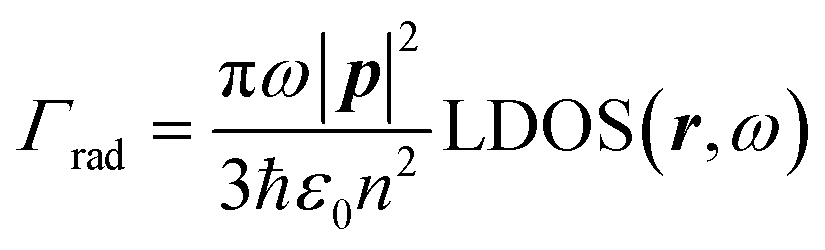
The radiative decay rate of a randomly oriented two-level emitter under the dipole approximation is given by:1| | 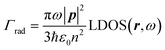 | (1) |
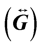
where p is the dipole moment of the quantum emitter, ω is the angular frequency of the emitted photon, ε0 is the dielectric permittivity of vacuum, n is the refractive index of the medium, ħ is the reduced Planck's constant and r is the position of the dipole. In turn, the LDOS is proportional to the trace of the dyadic Green function  according to:
| | 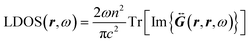 | (2) |
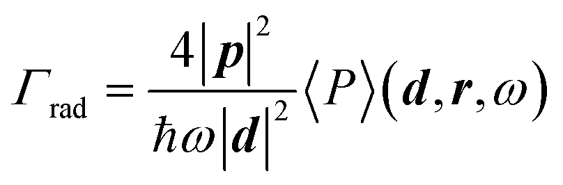
being c the speed of light in vacuum. In this way, LDOS is completely determined only by the magnetic permeability μ, n and the geometry of the system. The analytical calculation of Γrad through the LDOS in arbitrary structures is not straightforward, and in the case of a random dense packing of nanoparticles the problem becomes computationally burdensome as it involves the resolution of large linear systems.24 For this reason, FDTD simulations combined with dipole sources are typically used to calculate the enhancement of Γrad associated with the presence of complex photonic structures.25–27 Specifically, simulating the radiated power from an electric dipole antenna allows the calculation of Γrad as:1| |  | (3) |
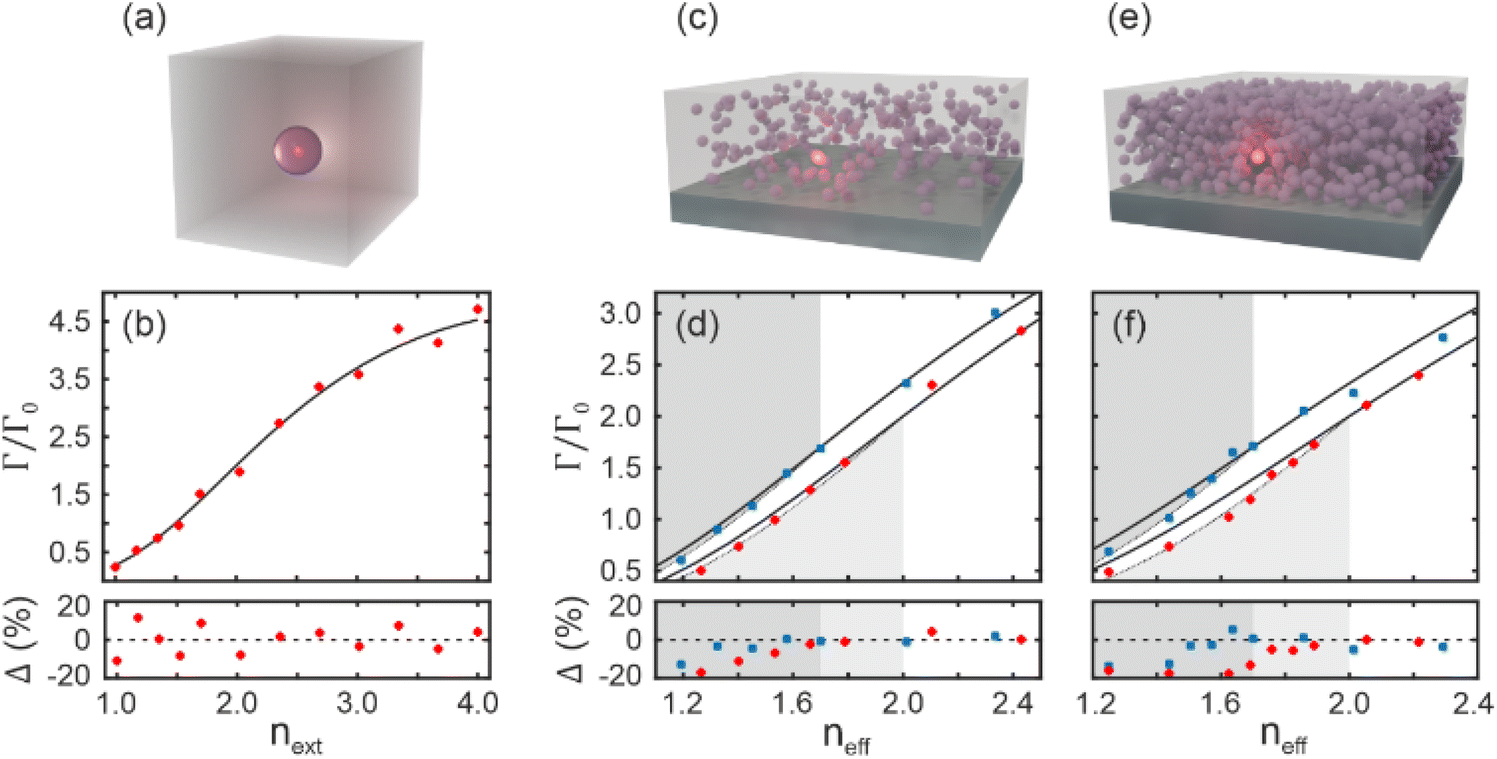
where d is the dipole moment of the antenna and 〈P〉 is the mean power radiated by the dipole. In the case of randomly oriented emitters, three orthogonal orientations of the dipole antenna should be calculated and averaged. This quantum classical connection provides an efficient way to calculate radiative rates in arbitrary structures, which we will use to assess the effect of interparticle interactions in nanoparticle thin films. We calculated Γrad/Γ0 -Γ0 being the radiative rate in vacuum- for an emitter in the center of a nanoparticle with a diameter of 50 nm and a refractive index nnp suspended in a homogeneous medium with a refractive index next, as shown in the schematic of Fig. 1a. The results are shown in Fig. 1b. We performed a series of simulations for nnp = 2.0 and calculated the relative difference Δ between the FDTD results and the exact solution of the problem given by  .28 Good agreement is found when comparing simulated and analytical results, with random values of Δ less than 16%, associated with the numerical error of the FDTD method. In what follows, we make use of a modified version of the analytical expression reported by Duan and Reid for the Γrad of a single nanoparticle in suspension in the limit where the size of the nanoparticle is much smaller than the wavelength:17
| |  | (4) |
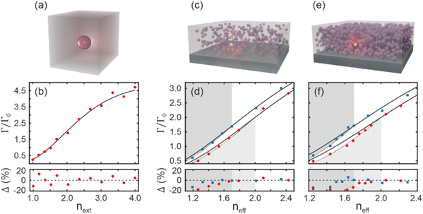 |
| | Fig. 1 (a) Schematic of a nanoparticle of refractive index nnp suspended in a homogeneous medium of refractive index next. (b) Simulated radiative rate (dots) of an emitter placed at the center of a particle suspended in a medium of refractive index next. Calculations obtained from the dyadic Green function are shown as a solid line for comparison. The relative difference between theory and simulations is shown in the lower panel. (c and e) Schematic of a system made of nanoparticles of refractive index nnp with a loading fraction cnp = 30% (c) and cnp = 64% (e). (d and f) Simulated radiative rates of an emitter placed at the center of a nanoparticle near the center of the films as a function of the effective index of the medium in which the emitter is embedded are shown as dots whereas the calculations given by the dyadic Green function of a particle suspended in the same effective medium are shown as solid lines. Red dots correspond to nanoparticles with nnp = 2.0, while the blue dots correspond to nanoparticles with nnp = 1.7. All the calculations were performed for nanoparticles with a radius of 25 nm. Our correction to the cavity model is plotted as a dotted line in (d) and (f). | |
In our case, as an effective medium is considered, the medium refractive index (next) shall be substituted by neff, constituting what we will refer to as the particle in effective medium (PEM) model. To account for interparticle interactions in a film, we then calculated the 〈P〉 of an electric dipole antenna placed at the center of a nanoparticle thin film with a moderate filling fraction (cnp = 30%) for two different values of the nnp -specifically nnp = 1.7 and 2.0- as a function of the neff, as shown in Fig. 1c. Note that neff of any material is a function of the indices of its individual constituents (ni) and their respective loading fraction (ci). In the case of a nanoparticle thin film, we have:
| | | neff = F(nnp,cnp,npore,cpore) | (5) |
where
npore and
cpore are the refractive index and the filling fraction of the material filling the pores between the nanoparticles. The function
F can be given by any of the existing effective medium approximations (EMA). In this work, the Bruggeman effective medium approximation was used because it describes media with moderate and high values of
cnp.
29 In addition, the
neff of the film was modified in the simulation either by changing
npore or by introducing nanoparticles with a lower
nnp into the film. Note that, unlike other proposed models,
18 our approach can be extended to composite films consisting of more than one type of nanoparticles. Our simulations consider a layer of thickness 500 nm, but the results are not dependent on this parameter. For the moderate
cnp under consideration, an almost identical dependence of
Γrad on the refractive index to that expected for a nanoparticle suspended in a homogeneous medium with an index
neff (see
Fig. 1d) is found, as already reported for nanocrystals in suspension.
11 However, slight discrepancies appear when increasing the refractive index difference between
nnp and that of the effective medium when
neff <
nnp, suggesting that the influence of particle interactions not considered in the EMA is overlooked in
eqn (4). More specifically, deviations between the
Γrad predicted by FDTD calculations and those estimated by the particle suspended in an effective medium model show up, especially when
neff <
nnp. This is explicit in simulations performed for a densely packed nanoparticle thin film with
cnp = 64%, sketched in
Fig. 1e, whose results are plotted in
Fig. 1f. Note that the asymmetric behaviour of the system with respect to the sign of the refractive index difference between
neff and
nnp stems from Mie theory. An intrinsic asymmetry in scattering efficiency is observed as a function of the refractive index difference between the particle and the surrounding medium (see Fig. S1
†). Additionally, our results serve to establish an approximate filling fraction range where the PEM model can be applied. In this context, attending to the reduced level of deviation from the PEM for
cnp = 30%, we can estimate the validity of the PEM for
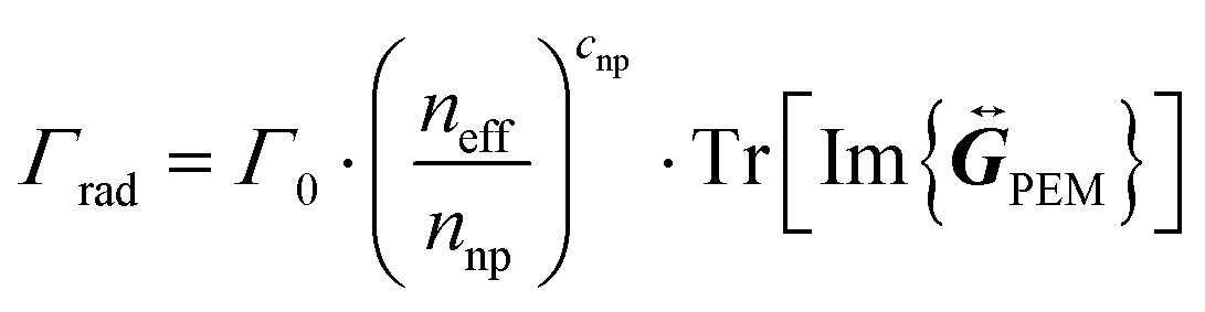
cnp < 30% for the refractive index values considered. We propose a correction in the expression of
Γrad given by
eqn (4) to account for the effect of interparticle interactions in layers made of luminescent nanoparticles. This correction is only valid when
neff <
nnp and takes the following form:
| |  | (6) |
where
cnp is given by the sum of each individual nanoparticle filling fraction
cnp,i in a composite, and

is the vacuum-normalized dyadic Green function in the PEM model. If the homogeneous refractive index is replaced by
neff and take the limit where the size of the nanoparticles is much smaller than the wavelength, our expression gives:
| | 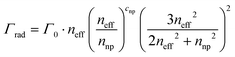 | (7) |
that fairly reproduces the dependence of
Γrad on
neff for all sets of simulations (see dotted lines in
Fig. 1d and f). Note that our correction does not include any empirical constants as fitting parameters. Instead, it involves only physical quantities:
nnp,
cnp and
neff. Moreover, it respects the bulk limit,
i.e. when the nanoparticles are embedded in a medium with the same index (
neff =
nnp, as in a dense layer),
Γ =
nnpΓ0.
18 Also, in the limit of low filling fraction,
i.e. cnp → 0, our correction recovers the expression of a particle in a homogeneous medium (
eqn (4)).
A case study: GdVO4:Eu3+-based nanoparticle thin films
Phosphor nanoparticles were chosen as the experimental probe to demonstrate the effect of neff on Γrad. Phosphors are key materials for efficient light generation due to their chemical and thermal stability combined with a high PLQY.30 In particular, we employ GdVO4:Eu3+ nanoparticles with an approximate size of 50 nm (see Fig. 2a), which exhibit bright PL with a narrow PL emission peak at λ0 = 620 nm when excited in the UV.30 These nanoparticles allow the preparation of thin films (see Fig. 2b) that are uniform in thickness and transparent in the visible spectral region. In addition, these nanophosphor films feature reduced light scattering,30 which allows neff to be determined using standard spectroscopic techniques. In fact, GdVO4:Eu3+ thin films have an neff = 1.4 in the visible range, as we will show later. To change the film index in a controlled way, in one approach, we prepare nanocomposite thin films made of GdVO4:Eu3+ and SiO2 nanoparticles of similar size (see Fig. 2c). By including as building blocks nanoparticles with a composition of lower refractive index (1.46 vs. 1.75) we manage to controllably reduce neff. Also, we take advantage of the accessible porosity of the films and infiltrate their void space with polymers, thus changing the refractive index of interstices between nanoparticles (npore), hence increasing neff. So, in order to access a wide range of neff values, uniform films with thicknesses ranging from 250 nm to 2 μm with different SiO2 to GdVO4:Eu3+cnp were prepared (see Fig. 2d) and then infiltrated with polymers: poly(methyl methacrylate) (PMMA, n = 1.49), polyvinyl alcohol (PVA, n = 1.48) or polydimethylsiloxane (PDMS, n = 1.40). Although the mixing of phosphor and SiO2 nanoparticles results in different film thickness values due to variations in particle concentration dispersion, this parameter does not change Γrad, as mentioned above. Please note that the approach herein taken allows tuning neff in a broad range, overcoming a common limitation in the study of photonic effects on the Γrad of luminescent nanoemitters.
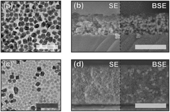 |
| | Fig. 2 (a) TEM image of GdVO4:Eu3+ nanoparticles. (b) Secondary (SE) and backscattered electrons (BSE) SEM images of a thin film made of GdVO4:Eu3+ nanoparticles. (c) TEM image of GdVO4:Eu3+ and SiO2 nanoparticles, the latter being less contrasted. (d) SE and BSE images of a cross section of a thin film with a ratio of GdVO4:Eu3+ to SiO2 nanoparticles of 0.22. The TEM scale bars correspond to 200 nm, while the SEM scale bars correspond to 500 nm. | |
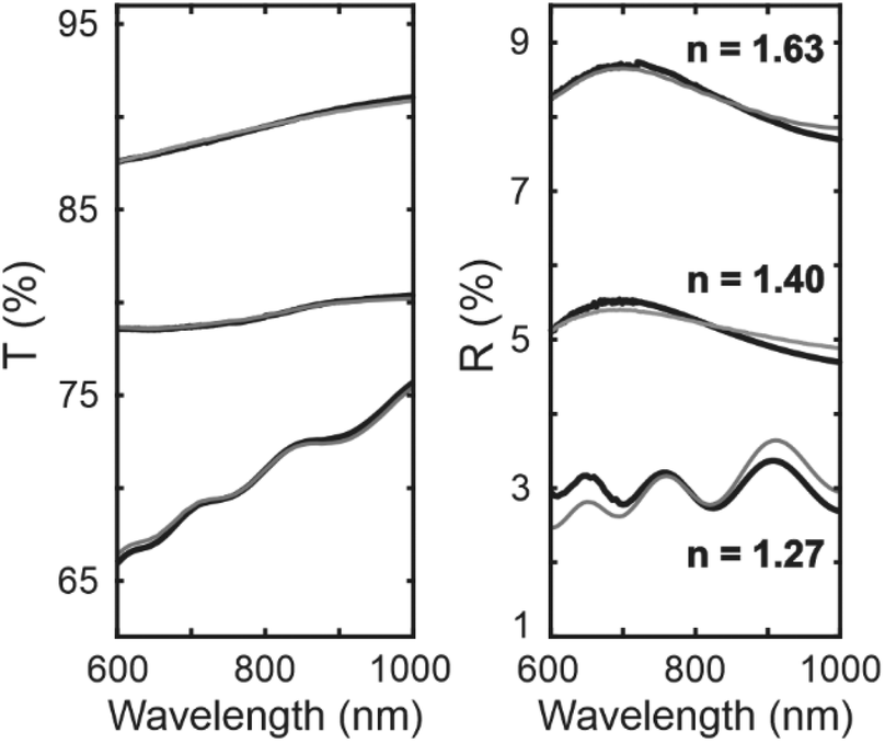
We extract the optical constants of our films by fitting the spectral dependence of the ballistic transmittance (T) and the specular reflectance (R) measured for different angles of incidence, following a procedure that has been thoroughly described before (see the Methods section).31 In Fig. 3 we show the experimental R and T (black lines) and their corresponding theoretical fits (grey lines) using the Bruggeman EMA. The calculated filling fraction of the only-nanophosphor films is cnp = 55 ± 5%. To account for the observed variation in the neff of the samples prepared in different batches, a certain spread was included in the calculated cnp and 55% was taken as the nominal value. The obtained neff of the GdVO4:Eu3+ films was neff = 1.40, which becomes neff = 1.63 when the air voids are infiltrated with PMMA, or neff = 1.60 when infiltrated with PDMS. Besides, we prepared composite films in which the SiO2 to GdVO4:Eu3+ volume ratio was varied as 1![[thin space (1/6-em)]](https://www.rsc.org/images/entities/char_2009.gif) :5, 1:1.25 and 1:0.22, resulting in neff = 1.37, 1.32, 1.27, respectively. Effective refractive index values were further confirmed by ellipsometry (see Fig. S2†).
:5, 1:1.25 and 1:0.22, resulting in neff = 1.37, 1.32, 1.27, respectively. Effective refractive index values were further confirmed by ellipsometry (see Fig. S2†).
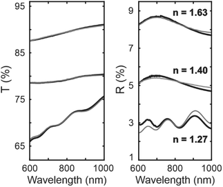 |
| | Fig. 3 Experimental transmittance and reflectance spectra (black lines) and corresponding theoretical fits (grey lines). The angle of incidence of the unpolarized light is 30°. The lower lines correspond to a composite made of GdVO4:Eu3+ and SiO2 nanoparticles, the middle lines correspond to a GdVO4:Eu3+ film and the upper lines correspond to a GdVO4:Eu3+ film embedded in PMMA. The calculated refractive index of each material is also shown. | |
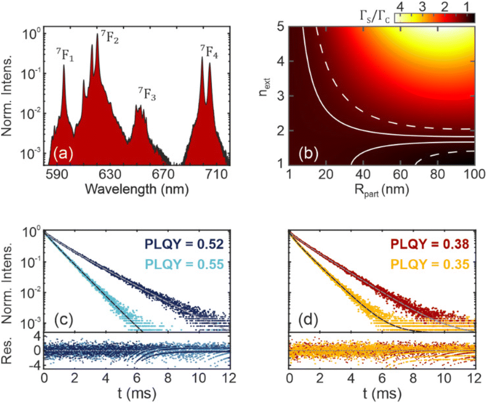
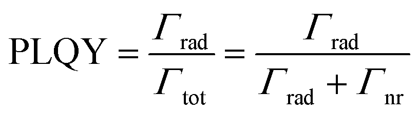
Eu3+ cations in our GdVO4 nanoparticles exhibit four main atomic transitions, giving rise to the measured PL spectra shown in Fig. 4a. Although these transitions are associated with the 5D0 excited state, they can exhibit different values of Γrad depending on the probability of the transition to the ground state. LDOS affect atomic transitions depending on their magnetic or electric nature.32 We calculated the ratio of the total intensities of the forced electric dipole FED and magnetic dipole (MD) transition32 and obtained a mean value of 11.49. Thus, the FED transitions are dominant in our system (5D0 → 7F2, 7F3, 7F4), allowing us to focus on the electric part of the LDOS. In addition, different radiative rates may be associated with a given atomic transition if, for example, the LDOS varies in the spatial region where Eu3+ cations are distributed within a nanoparticle. To shed light on this possible effect, in Fig. 4b we have used LDOS theory applied to spherical systems28 to calculate analytically the ratio of the Γrad of an emitter placed near the surface (ΓS) of a nanoparticle (nnp = 1.75) with radius Rpart, suspended in a homogeneous medium with refractive index next, to the Γrad of an emitter located at the centre of the same nanoparticle (ΓC). From these calculations, it can be concluded that Γrad varies by less than 5% within the volume of our nanoparticles, given the particle size and the next values considered. Therefore, LDOS variations within a nanoparticle are neglected in our analysis, as expected for nanoparticles which are much smaller than the wavelength.
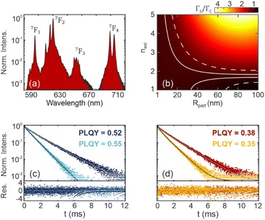 |
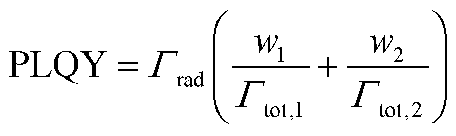
| | Fig. 4 (a) Experimental PL spectra of a GdVO4:Eu3+ nanoparticle film excited at 300 nm. The fundamental level of each Eu3+ transition is shown. (b) Calculated ratio between the radiative rate near the surface (ΓS) and at the center (ΓC) of a spherical nanoparticle with refractive index nnp = 1.75 for λ0 = 620 nm, as a function of the nanoparticle radius (Rpart) and the refractive index surrounding the nanoparticle (next). Solid (dashed) lines enclose the set of parameters for which the variation between ΓS and ΓC is less than 5% (20%). (c and d) Experimental photoluminescence decay for a GdVO4:Eu3+ film before (dark blue symbols) and after (light blue symbols) PMMA infiltration (c), and for a composite film made of GdVO4:Eu3+ and SiO2 nanoparticles before (red symbols) and after (yellow symbols) PVA infiltration (d). Fits are shown as black and grey curves. The residuals of the fits are shown in the lower part of the plots. Measured quantum yield values are also indicated in the upper part. | |
Time-dependent PL measurements were performed for the prepared samples to study the depopulation of 5D0 level after UV excitation (λexc = 300 nm) and hence, obtain Γrad (see Fig. 4c and d). This is given by the sum of the four main Eu3+ radiative transition rates. PL intensity I(t) is typically fitted using a bi-exponential model according to:
| | | I(t) = I0·[w1exp(−Γtot,1·t) + w2exp(−Γtot,2·t)] | (8) |
where
Γtot,i with
i = 1 or 2, is the total decay rate of the
ith component -sum of
Γrad,i and non-radiative decay rate (
Γnr,i)-,
wi is its corresponding weight and I
0 the initial PL intensity. Fits can be found in Fig. S3.
† The bi-exponential model has been reported to explain time-dependent PL measurements in RE-doped nanocrystals. It suggests that it is not possible to assign a single intrinsic rate to all the cations in our films. Although it has been shown that cross-relaxation and concentration quenching play an important role in the analysis of the time-dependent PL,
33 the physical origin of the bi-exponential model remains rather unclear. Some works attributed this behaviour to different local environments of RE cations in the lattice, assuming that different non-radiative decay paths occur near the surface or in the bulk of the nanoparticle,
34,35 while others explained the deviation from the single exponential behaviour according to an energy transfer process between the crystal host and cation acceptor.
36 Within this latter hypothesis, Inokuti and Hirayama developed a donor–acceptor energy transfer model,
37 which has been used to explain PL decay in RE-doped materials.
38–40 It succeeded in fitting experimental decays of YVO
4:Eu
3+ nanocrystals,
38 explaining the deviation from mono-exponential decay by attending to Eu–Eu multipolar interaction. However, although this model gave significantly better results than the single exponential model, the calculated bi-exponential fits were superior in our case (see Fig. S3
†).
Fig. 4c and d show measured PL decay spectra of the only-nanophosphor film (
Fig. 4c) and the composite film with the highest amount of SiO
2 (
Fig. 4d), before and after polymer infiltration. Bare films show similar average lifetime values (see Fig. S4
†), although they have different effective indices (1.40
vs. 1.27). Furthermore, polymer infiltration leads to a significant decrease in the lifetime for both cases while the PLQY hardly increases or even decreases (see Fig. S5
†), which cannot be explained by the modification of the optical environment alone. Therefore, the observed lifetime reduction results both from a modification of
Γrad according to
eqn (7) and the emergence of new non-radiative decay channels. We measure the PLQY, which can be defined as the ratio between radiative and total decay rates in order to extract
Γrad from
Γtot. In a general case, PLQY is given by the ratio between the radiative and total -sum of radiative and non-radiative- decay rates as:
| | 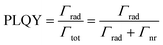 | (9) |
On the one hand, Γrad,1 = Γrad,2 in the biexponential model because the LDOS does not vary within a RE-doped nanoparticle. Considering this, PLQY can be expressed in the bi-exponential model -see the ESI† for a relationship between PLQY and transition rates in the Inokuti–Hirayama model- in the following manner:
| |  | (10) |
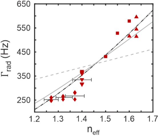
In this way, the combination of absolute PLQY measurements (see Fig. S5†) and PL decay fits enables a general way to discriminate the radiative contribution to the total rate, allowing us to calculate Γrad for films with different effective refractive index, as shown in Fig. 5. Experimental results indicate that Γrad follows an almost cubic dependence with neff. Note that the data in Fig. 5 are obtained using the biexponential model. However, our conclusions are independent of the model used (see Fig. S7†). Specifically, our results further support that Γrad in nanoparticle films deviates from the dependence expected from the PEM model (gray solid line) and rather behaves like the correction proposed in eqn (7) (black dashed dotted line). The strong dependence of Γrad with the neff reveals the enormous potential of refractive index engineering to increase the emission rate of luminescent films which can be key in Li–Fi (Light Fidelity) applications.41 In fact, the Γrad increases from 350 to 550 Hz with the infiltration of PMMA, achieving a 57% increase when the neff goes from 1.40 to 1.63.42 Although the PLQY is slightly higher when our nanophosphor films are embedded in polymers (from 0.52 to 0.55 with PMMA, see Fig. S5,† the improvement is less than expected (22%) considering the change in Γrad. To explain this, we also extracted Γnr (see Fig. S6 and S7†) and found that the non-radiative contributions increased when the nanophosphor films were modified, either by adding SiO2 nanoparticles or by infiltrating the films with polymers. We attribute this to a change in the chemical environment of the nanocrystals or their surface properties, inducing new non-radiative decay channels for the deexcitation of Eu3+ transitions that partially counterbalance the enhancement of Γrad. It highlights the relevance of limiting the impact of non-radiative decay channels in order to fully exploit the benefits of photonic effects in phosphor nanoparticles. These results support the use of our model to engineer the radiative rate of generic luminescent nanoparticle films, i.e., not only including those made of phosphor nanoparticles, as we have just demonstrated with the case study presented, but also others like dye-doped polymer beads or semiconductor nanocrystals.
 |
| | Fig. 5 Calculated radiative decay rate (Γrad) for films with different values of the effective refractive index (neff). The grey dashed line corresponds to linear scaling as expected for emitters in a homogeneous medium, the grey solid line is given by the LDOS calculation of a nanoparticle suspended in a medium with neff, and the black dashed dotted line corresponds to the proposed correction. Error bars are included to account for the variation in nanoparticle filling fraction between similar samples. Square points correspond to composite-based films, while triangles correspond to only-phosphor-based films. | |
Conclusions
We have demonstrated the feasibility of the FDTD method to calculate changes in the Γrad due to the optical environment, and applied this general method to elucidate the impact of the refractive index in luminescent nanoparticle thin films. We have found deviations from the PEM model as the film filling fraction increases, which have been accounted for in a correction based solely on physical parameters. The first experimental study of the dependence of the Γrad of luminescent nanocrystals on the neff of a thin film is also presented, with a detailed analysis of PL decays and PLQY measurements, which allowed us to discriminate between radiative and non-radiative processes taking place in our samples. The high level of agreement between theoretical and experimental results points at the refractive index modification in nanoparticle thin films as a straightforward and simple method to enhance or inhibit the radiative decay rate of light-emitting materials. Although fundamental in nature, our results hold great promise for applications where control of the emission rate is critical, such as lighting, medical imaging, or optical wireless communications.
Methods
Simulations
FDTD simulations were carried out using commercial software (Ansys©, Lumerical FDTD). All the calculations used a uniform discretization with 2 nm mesh and absorbing boundary conditions (PML).
For the case of a particle in a uniform medium, a simulation domain of (0.4 × 0.4 × 0.4) μm3 was used and an electric dipole was placed in the centre of the particle. A single orientation of the dipole was used, given the spherical symmetry of the system.
In the nanoparticle thin film simulations, simulation domain was of (1.0 × 1.0 × 1.1) μm3 and the thickness of the film was 500 nm. For the low filling fraction film, a random set of spheres was generated, while special code developed by others43 was used to generate a random close-packing of spheres. In these cases, three simulations of three orthogonal dipole orientations were performed and averaged to account for random dipole orientation. The dipoles were placed in the centre of a particle which is near the geometric centre of the film, which is chosen as a representative point of the film.
Synthesis of GdVO4:Eu3+ nanocrystals, nanocomposite and thin films
Synthesis of GdVO4:Eu3+ nanophosphor was performed following a solvothermal method previously reported.44 Eu3+ concentration was fixed at 10% (Gd0.9VO4:Eu0.13+). Briefly, uniform NPs were obtained through homogeneous precipitation reaction from the RE precursors and sodium orthovanadate in EG/water mixture at 120 °C. Polyacrylic acid (PAA) was added during the synthesis as functionalization agent. As a result, sized-controlled nanophosphors with colloidal stability dispersed in methanol were attained.
Nanocomposite dispersion by directly adding certain volume of LUDOX® TMA colloidal silica (34 wt%) suspension in water to the GdVO4:Eu3+ suspension in methanol. Various suspensions with distinct SiO2/GdVO4 ratios were prepared and sonicated for 15 min to avoid aggregation.
Thin films were prepared by spin coating over fused silica substrates and annealed at 500 °C for 1 h to remove organic binders and improve GdVO4:Eu3+ crystallinity.
Infiltration with polymers was performed by drop casting in all cases. In the case of PMMA, a 5 wt% solution in anisole was deposited over the thin film, and no heating was applied to evaporate the solvent. For PVA, a 1 wt% solution in water was deposited and heated at 70 °C for 1 h to evaporate the solvent. PDMS was prepared by mixing 9 parts in weight of Sylgard 184 prepolymer and 1 part of curing agent. After vigorously mixing, the mixture was placed in vacuum to remove air bubbles. After the infiltration process, the sample was heated to 90 °C for 1.5 hours to enable polymerization.
Photoluminescence measurements
Emission spectra and time-dependent PL intensity were measured with an Edinburgh FLS1000 spectrofluorometer under an excitation of λex = 300 nm. Time-dependent PL measurements were registered for the most intense Eu3+ emission band at 620 nm using a MCS method and a pulsed xenon lamp at 40 Hz repetition rate. Time window was set to 20 ms with 4000 channels and a maximum count number of 5000.
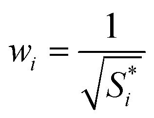
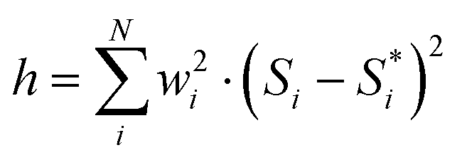
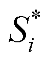
PL decay fittings were obtained from weighted least squares minimization. Poisson weights wi were considered, being the objective function h to minimize:
| | 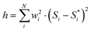 | (11) |
where

correspond to the experimental data, and
Si is the result of the fittings which depends on the fitting parameters -see
eqn (8)- and
N is the number of data points. The weights are given by the following expression:
| |  | (12) |
Finally, the chi-square parameter (χ2) can be calculated as h/N.
Quantum yield measurements
Absolute quantum yield measurements were performed in a Hamamatsu Photonics equipment consisting in an integrating sphere connected to a photo spectrometer and to a xenon lamp as excitation source. This equipment is able to count the number of absorbed and emitted photons, estimating the PLQY.
Refractive index determination
Refractive index determination was carried out by theoretically fitting R and T spectra measured for three different incident angles in a commercial Cary 5000 UV-Vis-NIR coupled to a double goniometer (UMA accessory). The transfer matrix method is used to theoretically calculate R and T at the same angles of incidence and then to minimize the difference between experimental data and calculations by varying the refractive index of the film and its thickness. Our model accounts for a small fraction of scattering given by the experimental 1-R-T, as our samples are non-absorbing in the visible. It also allows for some variation in film thickness to account for thickness inhomogeneity in thick films. Finally, a commercial variable angle spectroscopic ellipsometer (VASE) from J.A. Woollam Co., Inc. was used to confirm the refractive index data.
Abbreviations
| EMA | Effective medium approximation |
| FDTD | Finite-difference time-domain |
| LDOS | Local density of optical states |
| PEM | Particle in effective medium |
| PL | Photoluminescence |
| PLQY | Photoluminescence quantum yield |
| RE | Rare earth |
Data availability
Data for this paper are available at Digital CSIC at https://doi.org/10.20350/digitalCSIC/15509. The code for estimating the effective refractive index of an arbitrary layered optical material may be found at https://github.com/Multifunctional-OpticalMaterials-Group.
Conflicts of interest
There are no conflicts to declare.
Acknowledgements
This project has received funding from the European Research Council (ERC) under the European Union's Horizon 2020 Research and Innovation Programme (NANOPHOM, grant agreement no. 715832), from the BBVA Foundation Leonardo Grant for Physics Researchers 2023, and from MCIN/AEI/10.13039/501100011033 by European Union NextGeneration EU/PRTR under grant TED2021-129679B-C22.
References
- W. L. Barnes, S. A. R. Horsley and W. L. Vos, Classical Antennas, Quantum Emitters, and, Densities of Optical States, J. Opt., 2020, 22, 073501 CrossRef CAS.
- K. H. Drexhage, Influence of a Dielectric Interface on Fluorescence Decay Time, J. Lumin., 1970, 1–2, 693–701 CrossRef.
- K. H. Drexhage, H. Kuhn and F. P. Schäfer, Variation of the Fluorescence Decay Time of a Molecule in Front of a Mirror, Bunsen-Ges. Phys. Chem., Ber., 1968, 72, 329–329 CrossRef.
- D. Geng, E. Cabello-Olmo, G. Lozano and H. Míguez, Tamm Plasmons Directionally Enhance Rare-Earth Nanophosphor Emission, ACS Photonics, 2019, 6, 634–641 CrossRef CAS PubMed.
- D. Geng, E. Cabello-Olmo, G. Lozano and H. Míguez, Photonic Structuring Improves the Colour Purity of Rare-Earth Nanophosphors, Mater. Horiz., 2018, 5, 661–667 RSC.
- D. Englund, D. Fattal, E. Waks, G. Solomon, B. Zhang, T. Nakaoka, Y. Arakawa, Y. Yamamoto and J. Vučković, Controlling the Spontaneous Emission Rate of Single Quantum Dots in a Two-Dimensional Photonic Crystal, Phys. Rev. Lett., 2005, 95, 013904 CrossRef PubMed.
- J. M. Viaña, M. Romero, G. Lozano and H. Míguez, Nanoantennas Patterned by Colloidal Lithography for Enhanced Nanophosphor Light Emission, ACS Appl. Nano Mater., 2022, 5, 16242–16249 CrossRef PubMed.
- J. A. Schuller, E. S. Barnard, W. Cai, Y. C. Jun, J. S. White and M. L. Brongersma, Plasmonics for Extreme Light Concentration and Manipulation, Nat. Mater., 2010, 9, 193–204 CrossRef CAS PubMed.
- A. Jiménez-Solano, J. F. Galisteo-López and H. Míguez, Absorption and Emission of Light in Optoelectronic Nanomaterials: The Role of the Local Optical Environment, J. Phys. Chem. Lett., 2018, 9, 2077–2084 CrossRef PubMed.
- O. L. Muskens, V. Giannini, J. A. Sánchez-Gil and J. Gómez Rivas, Strong Enhancement of the Radiative Decay Rate of Emitters by Single Plasmonic Nanoantennas, Nano Lett., 2007, 7, 2871–2875 CrossRef CAS PubMed.
- T. Senden, F. T. Rabouw and A. Meijerink, Photonic Effects on the Radiative Decay Rate and Luminescence Quantum Yield of Doped Nanocrystals, ACS Nano, 2015, 9, 1801–1808 CrossRef CAS PubMed.
- S. F. Wuister, C. De Mello Donegá and A. Meijerink, Local-Field Effects on the Spontaneous Emission Rate of CdTe and CdSe Quantum Dots in Dielectric Media, J. Chem. Phys., 2004, 121, 4310–4315 CrossRef CAS PubMed.
- E. He, H. Zheng, X. Zhang and S. Qu, Local-Field Effect on the Fluorescence Relaxation of Tm3+:LaF3 Nanocrystals Immersed in Liquid Medium, Luminescence, 2010, 25, 66–70 CrossRef CAS PubMed.
- X. Xue, T. Suzuki, H. T. Tong and Y. Ohishi, Investigation of Local Field Effect of α-NaYF4:Nd3+ Nanocrystals, Phys. Status Solidi C, 2012, 9, 2481–2484 CrossRef CAS.
-
K. Dolgaleva, R. W. Boyd and P. W. Milonni, Influence of Local-Field Effects on the Radiative Lifetime of Liquid Suspensions of Nd:YAG Nanoparticles, 2007 Search PubMed.
- R. S. Meltzer, S. P. Feofilov, B. Tissue and H. B. Yuan, Dependence of Fluorescence Lifetimes of Y2O3:Eu3+ Nanoparticles on the Surrounding Medium, Phys. Rev. B: Condens. Matter Mater. Phys., 1999, 60, R14012–R14015 CrossRef CAS.
- C. K. Duan and M. F. Reid, Macroscopic Models for the Radiative Relaxation Lifetime of Luminescent Centers Embedded in Surrounding Media, Spectrosc. Lett., 2007, 40, 237–246 CrossRef CAS.
- K. K. Pukhov, T. T. Basiev and Y. V. Orlovskii, Spontaneous Emission in Dielectric Nanoparticles, JETP Lett., 2008, 88, 12–18 CrossRef CAS.
- D. Toptygin, Effects of the Solvent Refractive Index and Its Dispersion on the Radiative Decay Rate and Extinction Coefficient of a Fluorescent Solute, J. Fluoresc., 2003, 13, 201–219 CrossRef CAS.
- Y. Luo, L. Li, H. T. Wong, K. Wong and P. A. Tanner, Importance of Volume Ratio in Photonic Effects of Lanthanide–Doped LaPO4 Nanocrystals, Small, 2020, 16(1), 1905234 CrossRef CAS PubMed.
- C. Feldmann, Luminescent Nanomaterials, Nanoscale, 2011, 3, 1947 RSC.
- J. F. Galisteo-López and G. Lozano, Nanophotonics for Current and Future White Light-Emitting Devices, J. Appl. Phys., 2021, 130, 200901 CrossRef.
- B. Casabone, C. Deshmukh, S. Liu, D. Serrano, A. Ferrier, T. Hümmer, P. Goldner, D. Hunger and H. de Riedmatten, Dynamic Control of Purcell Enhanced Emission of Erbium Ions in Nanoparticles, Nat. Commun., 2021, 12, 3570 CrossRef CAS PubMed.
- A. P. Moneda and D. P. Chrissoulidis, Dyadic Green's Function of a Cluster of Spheres, J. Opt. Soc. Am. A, 2007, 24, 3437 CrossRef PubMed.
- C. Van Vlack and S. Hughes, Finite-Difference Time-Domain Technique as an Efficient Tool for Calculating the Regularized Green Function: Applications to the Local-Field Problem in Quantum Optics for Inhomogeneous Lossy Materials, Opt. Lett., 2012, 37, 2880 CrossRef CAS PubMed.
- A. Jiménez-Solano, J. F. Galisteo-López and H. Míguez, Fine Tuning the Emission Properties of Nanoemitters in Multilayered Structures by Deterministic Control of Their Local Photonic Environment, Small, 2015, 11, 2727–2732 CrossRef PubMed.
- K. A. Ivanov, K. M. Morozov, G. Pozina, A. R. Gubaydullin, E. I. Girshova and M. A. Kaliteevski, Control of the Surface Plasmon Dispersion and Purcell Effect at the Metamaterial-Dielectric Interface, Sci. Rep., 2020, 10, 20828 CrossRef CAS PubMed.
- L.-W. Li, P.-S. Kooi, M.-S. Leong and T.-S. Yee, Electromagnetic Dyadic Green’s Function in Spherically Multilayered Media, IEEE Trans. Microwave Theory Tech., 1994, 42, 2302–2310 CrossRef.
-
J. Humlicek, Data Analysis for Nanomaterials: Effective Medium Approximation, Its Limits and Implementations, in Ellipsometry at the Nanoscale, Springer Berlin Heidelberg, Berlin, Heidelberg, 2013, pp. 145–178 Search PubMed.
- D. Geng, G. Lozano and H. Míguez, Highly Efficient Transparent Nanophosphor Films for Tunable White-Light-Emitting Layered Coatings, ACS Appl. Mater. Interfaces, 2019, 11, 4219–4225 CrossRef CAS PubMed.
- A. Rubino, G. Lozano, M. E. Calvo and H. Míguez, Determination of the Optical Constants of Ligand-Free Organic Lead Halide Perovskite Quantum Dots, Nanoscale, 2023, 15, 2553–2560 RSC.
- Z. Wang, T. Senden and A. Meijerink, Photonic Effects for Magnetic Dipole Transitions, J. Phys. Chem. Lett., 2017, 8, 5689–5694 CrossRef CAS PubMed.
- R. Martín-Rodríguez, F. T. Rabouw, M. Trevisani, M. Bettinelli and A. Meijerink, Upconversion Dynamics in Er3+-Doped Gd2O2S: Influence of Excitation Power, Er3+ Concentration, and Defects, Adv. Opt. Mater., 2015, 3, 558–567 CrossRef.
- J. W. Stouwdam and F. C. J. M. Van Veggel, Near-Infrared Emission of Redispersible Er3+, Nd3+, and Ho3+ Doped LaF3 Nanoparticles, Nano Lett., 2002, 2, 733–737 CrossRef CAS.
- N. S. Singh, R. S. Ningthoujam, N. Yaiphaba, S. D. Singh and R. K. Vatsa, Lifetime and Quantum Yield Studies of Dy3+ Doped GdVO4 Nanoparticles: Concentration and Annealing Effect, J. Appl. Phys., 2009, 105, 064303 CrossRef.
- M. Yu, J. Lin and J. Fang, Silica Spheres Coated with YVO4:Eu3+ Layers via Sol-Gel Process: A Simple Method to Obtain Spherical Core-Shell Phosphors, Chem. Mater., 2005, 17, 1783–1791 CrossRef CAS.
- M. Inokuti and F. Hirayama, Influence of Energy Transfer by the Exchange Mechanism on Donor Luminescence, J. Chem. Phys., 1965, 43, 1978–1989 CrossRef CAS.
- M. Buijs, A. Meyerink and G. Blasse, Energy Transfer between Eu3+ Ions in a Lattice with Two Different Crystallographic Sites: Y2O3:Eu3+, Gd2O3:Eu3+ and Eu2O3, J. Lumin., 1987, 37, 9–20 CrossRef CAS.
- K. Lu, W. Han, G. Cheng, X. Zhu, S. Li, H. Guo, B. Gu, Y. Ye, J. Qi and T. Lu, Dy3+-Doped Y2Zr2O7 Highly Transparent Ceramics for Ultraviolet Excitable Warm White Light-Emitting Applications, J. Am. Ceram. Soc., 2023, 106(6), 3654–3662 CrossRef CAS.
- G. Mialon, S. Türkcan, A. Alexandrou, T. Gacoin and J. P. Boilot, New Insights into Size Effects in Luminescent Oxide Nanocrystals, J. Phys. Chem. C, 2009, 113, 18699–18706 CrossRef CAS.
- D. V. Guzatov, S. V. Gaponenko and H. V. Demir, Possible Plasmonic Acceleration of LED Modulation for Li-Fi Applications, Plasmonics, 2018, 13, 2133–2140 CrossRef CAS.
- T. Tsutsui, M. Yahiro, H. Yokogawa, K. Kawano and M. Yokoyama, Doubling Coupling-out Efficiency in Organic Light-Emitting Devices Using a Thin Silica Aerogel Layer, Adv. Mater., 2001, 13, 1149–1152 CrossRef CAS.
- V. Baranau and U. Tallarek, Random-Close Packing Limits for Monodisperse and Polydisperse Hard Spheres, Soft Matter, 2014, 10, 3826 RSC.
- N. O. Nuñez, S. Rivera, D. Alcantara, J. M. de la Fuente, J. García-Sevillano and M. Ocaña, Surface Modified Eu:GdVO4 Nanocrystals for Optical and MRI Imaging, Dalton Trans., 2013, 42, 10725 RSC.
Footnote |
| † Electronic supplementary information (ESI) available: Mie calculations of the scattering cross section of the luminescent nanoparticles (Fig. S1); ellipsometry data (Fig. S2); Inokuti–Hirayama model and time-dependent PL measurements (eqn (S1)–(S2) and Fig. S3); bi-exponential fitting parameters (Fig. S4); absolute PLQY values (Fig. S5); non-radiative rates (Fig. S6); relationship between PLQY and Grad for the Inokuti-Hirayama model (eqn (S3)); radiative, non-radiative and Eu–Eu rate for the Inokuti–Hirayama model (Fig. S7). See DOI: https://doi.org/10.1039/d3nr03348a |
|
| This journal is © The Royal Society of Chemistry 2023 |
Click here to see how this site uses Cookies. View our privacy policy here. 
 Open Access Article
 This Open Access Article is licensed under a Creative Commons Attribution-Non Commercial 3.0 Unported Licence
 ,
Juan Ramón
Sánchez-Valencia
,
Juan Ramón
Sánchez-Valencia
 according to:
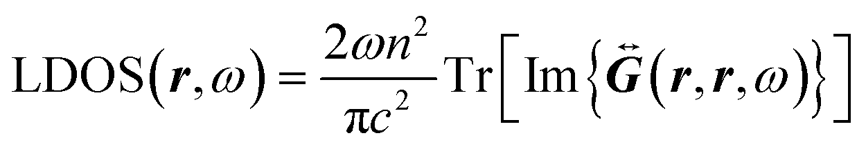
 .28 Good agreement is found when comparing simulated and analytical results, with random values of Δ less than 16%, associated with the numerical error of the FDTD method. In what follows, we make use of a modified version of the analytical expression reported by Duan and Reid for the Γrad of a single nanoparticle in suspension in the limit where the size of the nanoparticle is much smaller than the wavelength:17
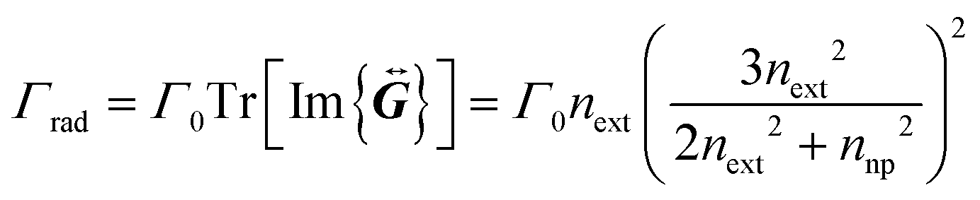
 is the vacuum-normalized dyadic Green function in the PEM model. If the homogeneous refractive index is replaced by neff and take the limit where the size of the nanoparticles is much smaller than the wavelength, our expression gives:
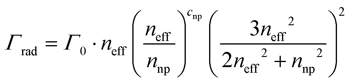

 correspond to the experimental data, and Si is the result of the fittings which depends on the fitting parameters -see eqn (8)- and N is the number of data points. The weights are given by the following expression: