DOI:
10.1039/D3NR03264G
(Paper)
Nanoscale, 2023,
15, 13371-13383
In silico prediction of protein binding affinities onto core–shell PEGylated noble metal nanoparticles for rational design of drug nanocarriers†
Received
5th July 2023
, Accepted 26th July 2023
First published on 27th July 2023
Abstract
Polymer-coated nanoparticles (NP) are commonly used as drug carriers or theranostic agents. Their uptake rates are modulated by the interactions with essential serum proteins such as transferrin and albumin. Understanding the control parameters of these interactions is crucial for improving the efficiency of these nanoscale devices. In this work, we perform a multiscale computational study of protein adsorption onto polyethylene glycol (PEG) coated gold and silver NPs, producing protein–NP adsorption rankings as a function of PEG grafting density, which are validated against previously reported experimental protein–NP binding constants. Furthermore, the applied nano-docking method provides information on the preferred orientation of proteins immobilised on the surface of NPs. We propose a method of construction of model core–shell NPs in silico. The presented protocol can provide molecular level insights for the experimental development of biosensors, nanocarriers, or other nanoplatforms where information on the preferred orientation of protein at the bio-nano interface is crucial, and enables fast in silico prescreening of assays of various nanocarriers, i.e., combinations of proteins, NPs, and coatings.
1. Introduction
Zero-valent noble metal nanoparticles (NP) have attracted much attention due to their unique physicochemical properties which make them suitable for use in theranostic nanoplatforms.1 Noble metal NPs are plasmon-resonant and hold great promise as a contrasting reagent for tumour targeting and imaging2–4 due to their strong and tunable optical absorption. However, a vast number of metallic NPs are known to be toxic.5 As a result of their high reactivity, they are a subject to a fast clearance from the bloodstream due to recognition by the mononuclear phagocyte system (MPS). This natural defence mechanism undermines the theranostic potential of pristine noble metal NPs as the shortened circulation times result in lower therapeutic dose.6 Simultaneously, after entering the blood stream the NP may undergo opsonisation and/or form a corona of adsorbed proteins.7 These processes give NP a new “fake” identity which enables it to avoid the MPS, circulate for a longer time and be bioaccumulated in various organs, including otherwise inaccessible tissues.
Capping the metallic core with polymeric matter (e.g. with polyethylene glycol, PEG) was proven to be a good strategy to improve the performance of Au and Ag NPs for bio medical applications. This method substantially reduces the toxicity8 of these NPs, making them a good reference system for designing non-toxic drug nanocarriers (NC). The decrease in toxicity of PEGylated NPs is linked to a stealth effect of the polymeric shell, which suppresses the opsonisation of the NP. This stealth effect alters the saturation kinetics of NPs in a blood plasma, resulting in a prolonged circulation time, which in turn aids the NP in attaining the required therapeutic concentration.9,10 Thus, PEGylation has become a gold standard strategy for improving biocompatibility of engineered NPs.11–13 It also provides a tool for controlling the protein composition of the biomolecular corona formed on the NP surface. The cloaking effect of the shell on the surface of NPs does not cancel out the adsorption of blood plasma proteins entirely.14 Several proteins were reported to bind onto the polymer-modified surfaces, e.g., the binding of clusterin to ovalbumin NCs (OVA-NCs).15 Harnessing such interactions with NP offers a path towards novel NCs.
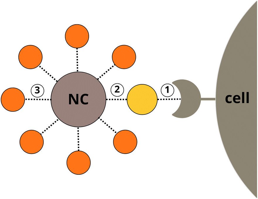
The selectivity and the efficiency of a NC can be optimised by balancing protein binding affinities at three separate interfaces (Fig. 1): (1) between cell membrane receptors and a coupled protein adsorbed to the NC, (2) between the NC and the protein, (3) between the NC and opsonins (e.g. albumins) competing with the coupled protein for the NP surface. The protein–protein binding is largely predetermined by natural selection and cannot be easily modified, but the bio-nano interaction can be artificially designed to be a selective non-covalent binding. Ideally, this interaction is not only energetically favourable as compared to opsonin binding, but also orientation-specific to allow the active site of the protein to remain available for association with a cell membrane receptor. Experimental identification of a perfect co-working triad – a suitable NP with specific physicochemical properties, a cell receptor, and a coupled protein – would require a tedious and extensive systematic experimental search. To overcome this bottleneck in silico rational drug design approaches can be applied.
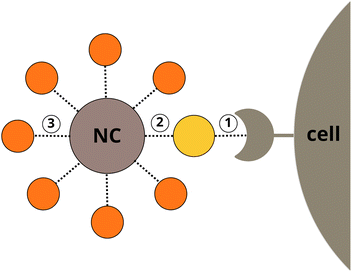 |
| | Fig. 1 Interactions of a nanocarrier: target protein–cell membrane receptor (1), target protein–NP (2), and biocorona–NP (3). | |
The selectivity for protein binding occurring at two competing protein–NP interfaces can be described in terms of the binding free energy (ΔGp–pbind) and (ΔGp–NPbind) and equilibrium association constants (Kp–peq) and (Kp–NPeq). In principle, these parameters can be predicted theoretically with high accuracy either by molecular dynamics (MD) combined with enhanced sampling approaches or by molecular docking techniques. While many successful examples have been reported for protein–protein and protein–small molecule interactions16,17 the capacity of conventional computational tools for predicting (ΔGp–NPbind) for a relevant number of promising protein–NP combinations is limited due to the immense dimensionality of the atomistic models, broad variations in conditions applied for in vitro preparation of NC (e.g. pH or ionic strength), the diverse structures of NPs (different surface chemistries, composite structures, etc.)18–20 or simply due to the lack of the force field parameters describing the inorganic NPs in simulations. Therefore, approximations must be employed to simplify the problem.
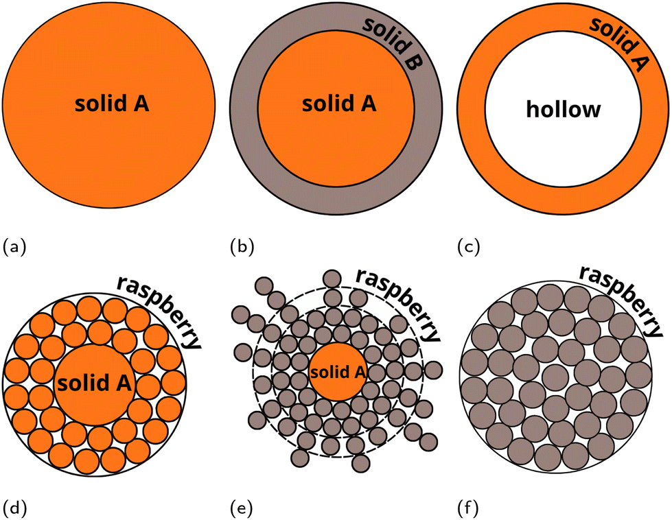
Recently, we presented a multiscale approach – the UnitedAtom (UA) methodology and software suite for predicting protein adsorption affinities for nanoscale materials,21,22 parameterised for a range of materials including titanium dioxide, quartz, carbon nanotubes, multiple metals and metal oxides, and surface-modified graphene.21,23–26 The UA method utilises a coarse-grained (CG) approach and uses pre-calculated interactions between molecular fragments of biopolymers (e.g. amino acids (AA) or side-chains of AAs (SCA) in peptides) and the target material. The total protein–NP interaction potential is obtained by summation of individual interaction potentials for AAs of a specific protein in a 3D arrangement with the NP and extracting orientation-specific binding energies from these potentials. The UA method requires less computational effort for predicting protein binding affinities as compared to conventional simulations techniques and finds good agreement for the prediction of binding patterns of individual proteins,26 enabling the simulation of competitive adsorption of multiple proteins.27,28 In this work, we extend the UA method to coated NPs to include the effects of surface chemistry on protein adsorption without explicit recalculation of the input NP–AA potentials for modified surfaces, avoiding the need to recalculate the interaction potentials for each substrate and surface functionalisation via lengthy MD simulations combined with AWT-Metadynamics, as was required for modified graphene.29,30 The extension of the UA method targets the adsorption of proteins onto composite NPs consisting of a solid core and a soft polymeric shell. To cover various possible core–shell structures, we introduce a “LEGO”-like modular approach (Fig. 2). Within this scheme, the interaction between AA side chains analogues (SCAs) and components of the NP (including surface chemistry elements) is modelled via sets of separate potentials for the interactions between each SCA and a component of the NP. To test and validate this novel methodology, we have performed multiscale modelling of protein adsorption onto PEGylated (poly(ethylene)glycol-coated) silver and gold core–shell NPs. These systems were previously studied in works31,32 where the protein binding characteristics for competitive adsorption of selected proteins were measured experimentally.
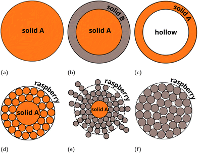 |
| | Fig. 2 Examples of “LEGO” models of multicomponent NPs which can be simulated in the extended version of the UnitedAtom code. (a) Uniform density solid single material NP (original version21,22). (b) Composite NP made of n-layers of solid materials with uniform density (extended version). (c) Raspberry model single material NP (extended version). (d) Raspberry outer layer – solid core single material NP (extended version). (e) Solid uniform density outer layer – hollow core single material NP (extended version). (f) Raspberry outer layer – solid core dual material NP (extended version). Raspberry models (c, d and f) may be used for representing nanocomposites, heteropolymers or mixed coatings. In this case different potentials corresponding to different components of the NP should be assigned to the raspberry beads. | |
2. Methods
2.1. Overview of the UnitedAtom multiscale method
Here, we briefly describe the UnitedAtom model for the prediction of protein–NP binding energies. The original method models variously shaped NPs as homogeneous entities with uniformly distributed density across the NP volume. The interaction between NP and a rigid protein is represented as a sum of electrostatic and non-bonded (including e.g. van der Waals (vdW), dipolar, and excluded volume effects) interactions, which is calculated through a summation of corresponding interaction energy terms between each AA and the NP as a function of the distance between the bead and the surface and a overall orientation of the protein defined by the angles θ and ϕ:| | 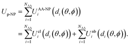 | (1) |
The orientation is defined relative to the input protein structure such that the initial structure is rotated first by −ϕ around the z-axis followed by a rotation of 180° − θ around the y-axis, and translated such that the centre of mass of the protein lies on the z-axis of the centre of mass of the NP. Following this procedure, the vector originally defined by (cos![[thin space (1/6-em)]](https://www.rsc.org/images/entities/char_2009.gif) ϕsinθ, sinϕsinθ, cosθ) is now aligned to (0, 0, −1), i.e. pointing towards the “North pole” of the NP.23 The non-bonded interaction at the short distances are obtained from atomistic MD simulations and augmented with an integrated VdW potential to cover the remaining volume of the NP. It should be pointed out that the interaction between the NP and the protein backbone in the UA model is not included in the short-range interaction potential and only taken into account within the long-range VdW potential. More details on the theoretical background for the UA model can be found elsewhere.21,23,25,26
ϕsinθ, sinϕsinθ, cosθ) is now aligned to (0, 0, −1), i.e. pointing towards the “North pole” of the NP.23 The non-bonded interaction at the short distances are obtained from atomistic MD simulations and augmented with an integrated VdW potential to cover the remaining volume of the NP. It should be pointed out that the interaction between the NP and the protein backbone in the UA model is not included in the short-range interaction potential and only taken into account within the long-range VdW potential. More details on the theoretical background for the UA model can be found elsewhere.21,23,25,26
Here, we extend the model to composite NPs with a non-uniform density, e.g. multi-component NPs with various polymeric coatings or core–shell NPs. This is achieved by representing a complex NP as a set of smaller building blocks (“NP components”), parameterisation of their interactions with AAs, and summing the above potentials over all the NP components, similar to the summation of the NP–AA potential over all the AA beads in a protein. Each NP component is described using the same set of parameters employed for the initial UnitedAtom model together with a set of coordinates describing the center of each component and an overall scaling factor for the potentials contributed by this component. Complex NP structures are assembled from combinations of these components, with negative scaling factors used to allow for the representation of hollow NPs or shells by subtracting a smaller NP from a larger one. Surface-modified NPs are represented as a set of beads of the brush material surrounding the core bead(s). Combinations of these shapes enable the simulation of complex NPs as shown in Fig. 1. We note that cylindrical and cubic NP components are also available but not further considered in the present work. If required, NPs can be represented by a raspberry-like construction to produce a more realistic model for complex shapes or agglomerations of individual NPs at the cost of an increase in computational time. This methodology assumes that the NP–AA potential is isotropic over the surface of the NP, which is not the case for low-density brushes in which all AA beads of a given type in a protein have the same interaction potential despite potentially having very different environments, e.g. direct exposure to the core or exposure to a brush only depending on their location in the protein. To mitigate this effect, we apply an additional hard-shell potential between brush beads and AA beads to penalise configurations with unrealistic protein-brush overlaps and average over NP orientations.
2.2. Generation of coarse-grained coordinates for core–shell NPs
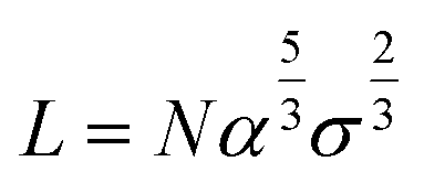
We model polymeric shell as a set of CG beads with a size equal to twice the radius of gyration of polymer fragments used in the UA model (see the corresponding section below). A full-length chain models of PEG5K, PEG10K, or PEG30K were represented by set of PEG trimers. CG models of PEG layers were constructed through a stochastic algorithm by placing PEG beads to match the target density profiles reflecting differences in grafting densities (Fig. 2, model f). This method allows the modeling of polymeric core–shell NPs with various grafting densities of the polymeric outer layer. The thickness of PEG layer (L) was either recovered from experimental information on the core radii and the total radii of the NPs or only from the total radii of the NPs with the help of Flory theory.33 Flory theory defines specific relationships between grafting density distance D, Flory radii RF for individual polymer chains and the shell morphology (layer thickness and grafting density) as follows:13| | 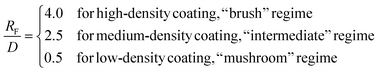 | (2) |
The experimentally measured Flory radius RF for PEG are known and were 5.6 nm for PEG5K, 9.29 for PEG10K34 and 14.0 for PEG30K.35 From 2, we find D and the area of the surface occupied by one chain is given by,
| |  | (3) |
such that the grafting density
σ (number of chains per nm
2) is,
| |  | (4) |
and the thickness of polymer layer can be estimated by,
| |  | (5) |
where
α is the length of the monomer (
α = 0.35 nm for a PEG unit
9) and
N is the number of monomer units in single polymer chain (
e.g. N = 113 for PEG5K). This gives grafting densities and the thickness of PEG layer,
e.g. the thickness of PEG5K shell for various regimes for case reviewed on sections 2 and 3 as shown in
Table 1.
Table 1 Example of predicted grafting density (σ) and corresponding thickness of polymer layer (L) for different coating densities of NPs studied in work31
| Regime |
“Mushroom” |
“Intermediate” |
“Brush” |
|
σ (chains per nm2) |
0.01 |
0.16 |
0.65 |
|
L (nm) |
0.921 |
5.847 |
14.733 |
After the thickness of the layer is identified we proceed with the placement of PEG CG beads. To account for the fact that the density of the polymeric shell is not uniform, we place CG beads in accordance to the normalised density profile ρ(L). If available, the experimental density can be used. Otherwise any other analytically defined density profile can be introduced. For the current case the following arbitrary function (a = 4.0 and b = 11.0) was selected to reconstruct normalised density profile:
| | 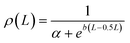 | (6) |
| | 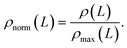 | (7) |
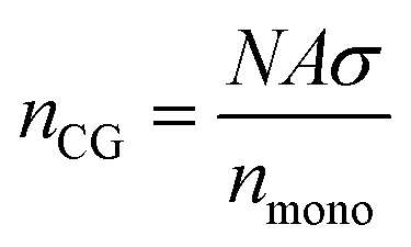
The resulting normalised density profiles were similar for the outer layer of PEGAgNP (52.7 nm) and PEGAuNP (35.7 nm) and are shown in Fig. S1 in the ESI.† The shell layer was populated with beads to a full loading capacity of the shell layer volume and was trimmed where needed to ensure that the total number of CG beads do not exceed the maximum number of CG beads nCG predicted by Flory theory:
| |  | (8) |
where
nmono is number of monomer units representing a single CG bead. For the current model
nmono = 3. The
GenerateNanoparticle.py tool from the UA package
36 was used to build coordinates for core–shell NPs with desired grafting density (
e.g. “mushroom”, “intermediate”, and “brush” in
Table 1 or Table S1 in the ESI
†). Additional “custom” models were generated based on the maximum number of CG beads
nCG estimated from the reported PEG5K concentrations utilised to synthesise NPs.
31 We assumed that 25%, 50% and 100% of reported PEG amount reacted. Due to different radii of the cores, these “custom” models reflected different grafting regimes for the same PEG amount in PEGAgNP and PEGAuNP (see Fig. S2 in the ESI
†). Radii and zeta potentials of NPs were taken from experiment (see Table S2 in the ESI
†). Reported experimental PEG grafting densities (see Table S3 in the ESI
†) and geometry
32 were taken as a starting point for generating CG configurations of the NPs from section 1
via similar approach.
2.3. UA calculations of adsorption affinities
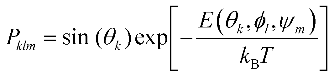
Adsorption affinities for each protein were obtained from three different surfaces of the FCC metallic core. Following our previous findings,26 Boltzmann averaging was applied to produce orientational averages. To account for the morphology of real NPs, which feature several surface types, we employ weighting factors wFCCi when calculating the final Eads(θ, ϕ), which reflect the different stability and surface area fractions (9) of each surface within the Wulff construction of the NP. The surface energy and area fractions for each surface of the FCC crystal were obtained from Material Project database.37,38 Since the binding energies are similar for each pristine surface, these approximate weights and averaging scheme do not significantly affect the final result. Moreover, the predicted maximal surface area fraction was equal to 0.8 for Ag(111) and 0.91 Au(111) surfaces, meaning that the impact of the remaining surfaces is minimal for final energy estimates. In cases where a polymeric shell was present on the metallic surface, the positions of the PEG CG beads were kept unchanged during the UA simulations and the protein “scans” the region above the NP surface along the z axis, normal to the surface of the core NP. To ensure that various density regions of the surface PEG shell are sampled by the protein during this scan, additional configurations were created by random rotation of the original NP coordinates around x, y, z axes defined by the collective variable ψm, and the weights in the total Boltzmann-weighted ensemble adjusted to account for this. Ultimately, each PEGAgNP and PEGAuNP modelled with various grafting density regime was represented by 60 CG configurations (m = 20 rotational configurations for i = 3 FCC surfaces each):| | 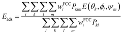 | (9) |
| |  | (10) |
where Pklm is the Boltzmann weighting factor and for k × l × m configurations of adsorption complexes and Pkl is the Boltzmann weighting factor for protein rotation configurations only.
The UA potentials between CG beads of the protein and the NP components were computed separately, with two sets of corresponding short-range surface potentials for the metallic core and polymeric shell on the surface. The parameterised set of short-range surface potentials for the silver FCC (100), (110), (111) surfaces were reported previously.26 The procedures for obtaining short-range surface potentials for metallic crystalline gold and unstructured PEG are described below.
2.4. Parameterisation of short-range non-bonded potentials for zero-valent gold surfaces
The PMFs for the three Au FCC surfaces reported here differ from the set of Au PMFs reported earlier for use with UA.21 The difference is that the prior set included Au(100) FCC configuration only, excluded salt, used different models for the SCAs, calculated NP–AA potentials with AMBER03 force field parameters, and employed different settings for the metadynamics, primarily a smaller initial hill height and further used a different non-bonding cut-off as imposed by the choice of force field. As was mentioned above, a more precise description of bio-interfaces for nanosized crystalline materials requires a more realistic interface generated from a combination of multiple FCC surfaces, motivating the inclusion of parameterising more Au FCC surfaces for UA. Furthermore, the averaging scheme described in section 3 should help to address the overestimation error observed previously.39 To obtain PMFs for inorganic crystalline materials we have followed the protocol described earlier.26,30 It is based on an adaptive well-tempered metadynamics (AWT-MetaD)40 scheme included in PLUMED29 software distribution. All-atom MD simulations in this study were performed with Gromacs package.41 InterfaceFF42,43 parameters, utilised for Au atoms, were combined with CHARMM3644 parameters, used for modelling TIP3P water and the “bio” part of the system. Coordinates of Au slabs for various FCC configuration (Miller indices (100), (110), and (111)) were obtained from CHARMM-GUI/Nanomaterial Modeler.45 Thirty-three biomolecular building blocks included in this study are shown in Fig. S3 in ESI.† Solvated “adsorbate-slab” systems were neutralised by 0.15 M KCl, corresponding to standard physiological conditions. The obtained systems (Fig. S4 in the ESI†) were pre-equilibrated to produce a proper density of aqueous solution around the NP. The temperature was set at 300 K in NPT and NVT ensembles, and the pressure was set at 1 bar in the NPT ensemble. The Nose–Hoover thermostat was invoked for NVT simulations, while the Berendsen weak coupling thermostat and barostat were applied for NPT runs. The system was modelled using periodic boundary conditions with the primary cells of 2.4 nm by 2.4 nm by 8.5 nm. In AWT-MetaD biased simulations producing the desired PMF, the SSD between NP and the biomolecular building block was sampled in the interval between 0.0 and 2.0 nm. Gaussian hills with an initial height of 2.5 kJ mol−1 were added along the trajectory every 0.5 ps. The bias factor was set at f = 20. The obtained PMFs for gold NPs are shown in Fig. S5 and S6 in ESI† (original files can be also found on Zenodo portal46). The PMFs for silver NPs employed here were previously published.26,47
2.5. Parameterisation of short-range non-bonded potentials for PEG polymeric shell
Preliminary tests for applying the AWT-MetaD protocol for bulk crystals to highly flexible or low-density materials have shown its unsuitability, as smaller adsorbates (e.g., the alanine SCA) were able to penetrate through the polymeric slab, which would not be possible for an actual residue during the adsorption of a protein. Furthermore, due to the extended length of the polymeric chains and their flexibility, a proper sampling of their movement was hard to achieve at the recommended trajectory time (400–600 ns). To overcome this problem, a different protocol for generating PMFs for polymeric materials was implemented. The PMF w(r) describing the pairwise interaction between two atoms (or two CG beads) can be recovered from the radial distribution functions g(r):48| | | W(r) = −kBT ln[g(r)]. | (11) |
In this approach, only a short part of the polymer (a trimer representing a single CG bead, as defined in section 2) was taken into consideration when modeling the pairwise interaction with the selected biomolecules (Fig. S3 in ESI†). To recover the PMF between CG breads of the biomolecule and polymeric brush, the simulation boxes composed of one biomolecular fragment and 64 PEG trimeric units were solvated and neutralised by 0.15 KCl (Fig. S7 in ESI†). After pre-equilibration and achievement of a proper density and/or pressure, production runs of duration 200 ns were performed. The resulting short-range potentials for UA model are shown in Fig. S7 in ESI† (original files can be also found on a Zenodo repository49). The long-range and electrostatic interactions in UA were handled as for other materials (see section 4).
2.6. Preparation of coordinates for protein structures and adsorption complexes
In total, we studied adsorption of seven peptides and proteins: H1.5 (FASTA: KVAKSPKKAKAW), H1.5-Cys (FASTA: KVAKSPKKCKAW), GSH (FASTA: ECG), WT GB3 (PDBID: 2OED), K19C CG3, BSA (PDBID: 3V03), TRF (PDBID: 2HAV), and ngTRF. Coordinates of GB3, BSA, and TRF proteins were obtained from the PDB.org portal.50–52 Glycans were removed from the original TRF PDB file to obtain coordinates for corresponding structure of ngTRF. For short peptides (H1.5 and GSH) where no PDB structures were available, the coordinates were generated from the sequence and CHARMM FF. Protein protonation states at experimental pH = 6.5 were evaluated using PropKa.53 Final coordinates were refined by CHARMM-GUI45 tools and a short equilibration simulation. CHARMM-GUI tools were also used to introduce side-chain mutations in H1.5-Cys and K19C CG3 proteins. The resulting structures were used as an input for the UA calculations to obtain adsorption energies as a function of their orientation relative to the NP surface. These results were analysed by an in-house Python script to obtain the positions of local minima and to reconstruct coordinates for adsorption complexes (docking) and to generate visualisations using NGLView.54
3. Results and discussion
Since the exact adsorption free energy (ΔGp–NPbind) values cannot be calculated within the UA framework26 due to the approximations involved, we have focused our study on the following model performance aspects: (a) ability to predict statistically accurate binding affinity rankings for selected core–shell PEGylated NP models and various proteins, (b) ability to reproduce the stealth effect caused by PEGylation of NPs, and (c) ability to reproduce differences in protein adsorption of transferrin variants as a result of glycosylation. According to reported CD spectra for the large proteins from the selected validation range, their adsorption onto NPs was not associated with drastic alterations of the globular structure and only small to moderate changes in α-helix, β-sheets, and the rest of the structure were intact.31 This observation suggests that the rigid protein approximation used in the UA model21,23,25,26 should not lead to significant errors, and that the overall methodology should remain suitable since it has been shown that small alterations to the structure produce only minor changes in adsorption energies.39
3.1. Accuracy of core–shell UA model for predicting protein adsorption
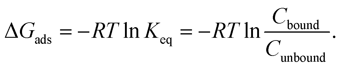
To validate the proposed core–shell UA model, we have performed simulations of adsorption of BSA, GSH, H1.5, H1.5-Cys, WT GB3, and K19C GB3 proteins onto PEG5KAuNPs, PEG10KAuNPs, and PEG30KAuNPs reported in the experimental study.32 In that work, the polymeric shell had a dense brush morphology for all three types of PEG shells. While PEG5K was expected to have a mushroom-like morphology even at high grafting densities, the longer chains of PEG10K and PEG30K were expected to form brush-like outer layers. It was suggested that adsorption of these proteins was mostly controlled by their size and the accessibility of thiol groups for interactions with a gold core during their frequent temporary penetrations through the PEG layers. Smaller H1.5 peptides were stronger bound as compared to larger BSA. Cysteine-rich proteins have shown a stronger binding as compared to Cys-depleted sequences (e.g. K19C GB3 vs. WT GB3 or H1.5-Cys vs. H1.5). The reported values of bound Cbound and unbound Cunbound protein concentration after corona stabilisation were used to estimate adsorption energy via:| | 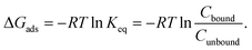 | (12) |
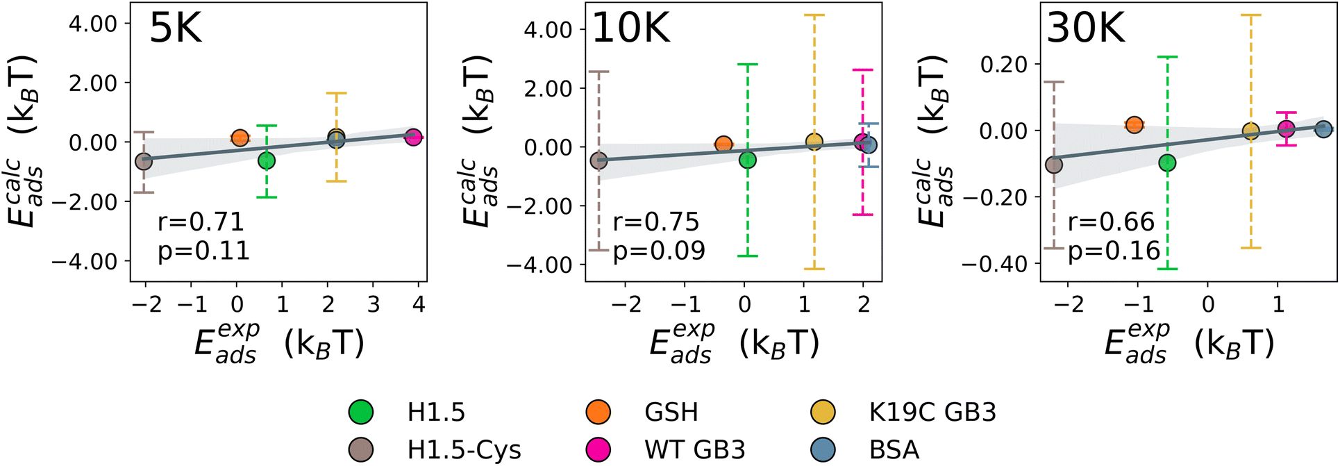
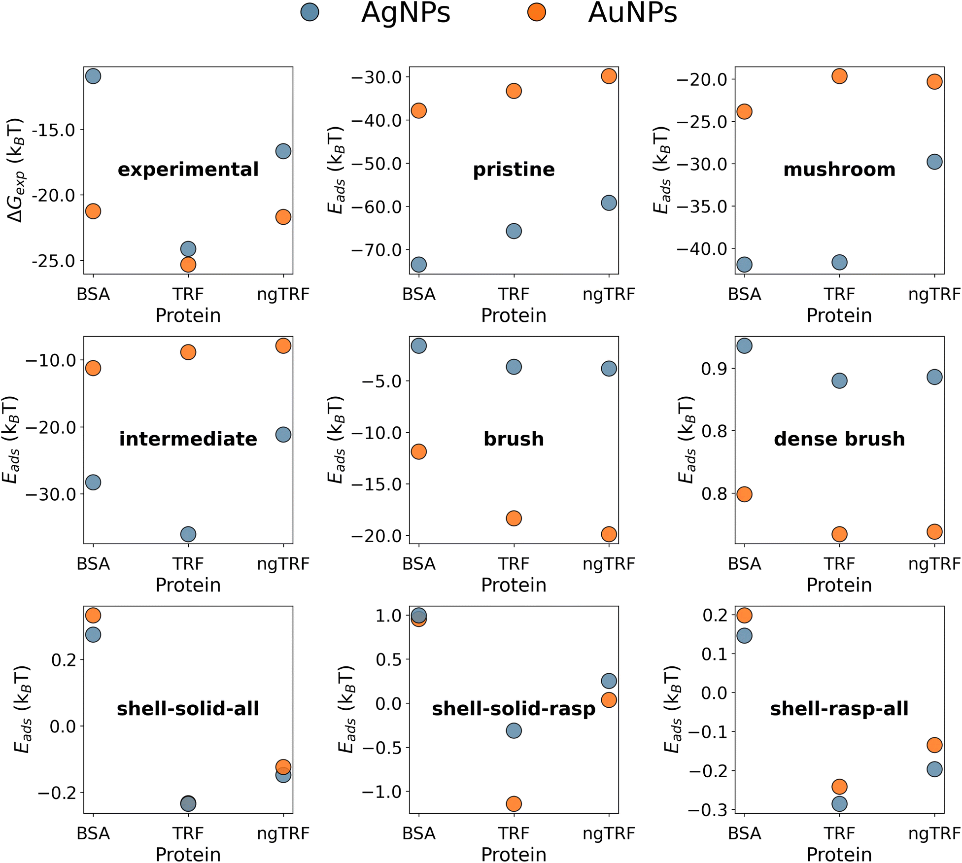
The UA-calculated adsorption energies for selected proteins correlated with experimentally reported values when considered across multiple NPs (Fig. 3 and 5), with a weak sensitivity shown to closely related proteins on a fixed NP, with e.g. typical correlation coefficients for a set of similar proteins on one NP on the order of r > 0.66 with p < 0.16. The lack of a stronger correlation stems from the relatively weak binding of proteins to PEGylated NPs, with subtle differences between different proteins which the UA model generally cannot readily distinguish due to the presence of random noise in the internal algorithms employed outweighing these small differences. Nonetheless, we note that the differences on the order of under 1kBT are well within the effects of thermal fluctuations and so do not necessarily reflect physically meaningful differences. Compared across different NPs, the core–shell model was able to generally identify the existence of the stealth effect from PEGylation of NPs. There is weak evidence that the UA model was able to predict the preferred binding of smaller proteins and potentially a minor preference for the binding of Cys-rich proteins compared to the Cys-depleted form. However, the binding energies across differing Mw of PEG shell were consistently small (−0.66–0.06kBT (PEG5K), −0.47–0.17kBT (PEG10K), −0.10–0.61kBT (PEG30K)) and did not reproduce the experimentally observed binding trend (PEG30K > PEG10K > PEG5K).
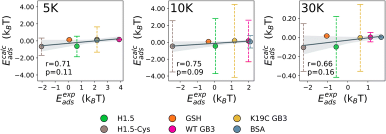 |
| | Fig. 3 The correlation between predicted and experimentally obtained adsorption energies for BSA, GSH, and mutants of H1.5 and GB3 proteins. | |
3.2. Predicting adsorption affinity rankings and stealth effect: the role of PEG grafting density
The experimental data suggest that the binding of TRF variants to citrated AuNPs and AgNPs with various diameters (13–60 nm) is weaker than the binding of BSA to the same NPs, with the exception of ngTRF adsorbed to smaller AuNPs.31 However, the addition of a 5K PEG shell to the spherical AuNPs and AgNPs reversed the adsorption affinity rankings, making the naturally occurring glycosylated variant of TRF the strongest binding protein in the set and the BSA the weakest one. To explain the difference in binding affinities for coated and uncoated NPs we have constructed multicomponent UA models of pristine and core–shell NPs. It is known that polymeric coatings on the surface of a NP can influence protein adsorption considerably.55 Elevated grafting density and/or high molecular weight of the polymer (high-density brush regime) was shown to enhance the antifouling characteristics of NPs by reducing protein adsorption.56–58 Since no information was reported on the exact morphology of the polymer layer in the original study, we used Flory theory33,59,60 to produce CG models of core–shell PEGAuNPs and PEGAgNPs (see section 2). The theory suggests that the grafted polymer chains change their shape between two limiting-case conformations – “mushroom” (low density) and “dense brush” (high density) upon increase of the grafting density σ. The intermediate grafting densities lead to mixed states of the polymer chains. The boundary between “mushroom” and “brush” regimes is controlled by the ratio between the mean chain-to-chain distance on the NP surface D and Flory radius RF for a single polymer chain. Four core–shell Ag and Au NPs with varying grafting densities of 5K PEG (σ = 0.01–1.02 chains per nm2) utilised for UA calculations are shown in Fig. 4. Additional solid uniform single-material NPs for each core material representing bare 35.7 nm AuNPs and 52.7 nm AgNPs (Fig. 4a and i) and two solid single-material PEG NP with diameters corresponding to experimental radii (Fig. 4g and n) were added to the set for comparison.
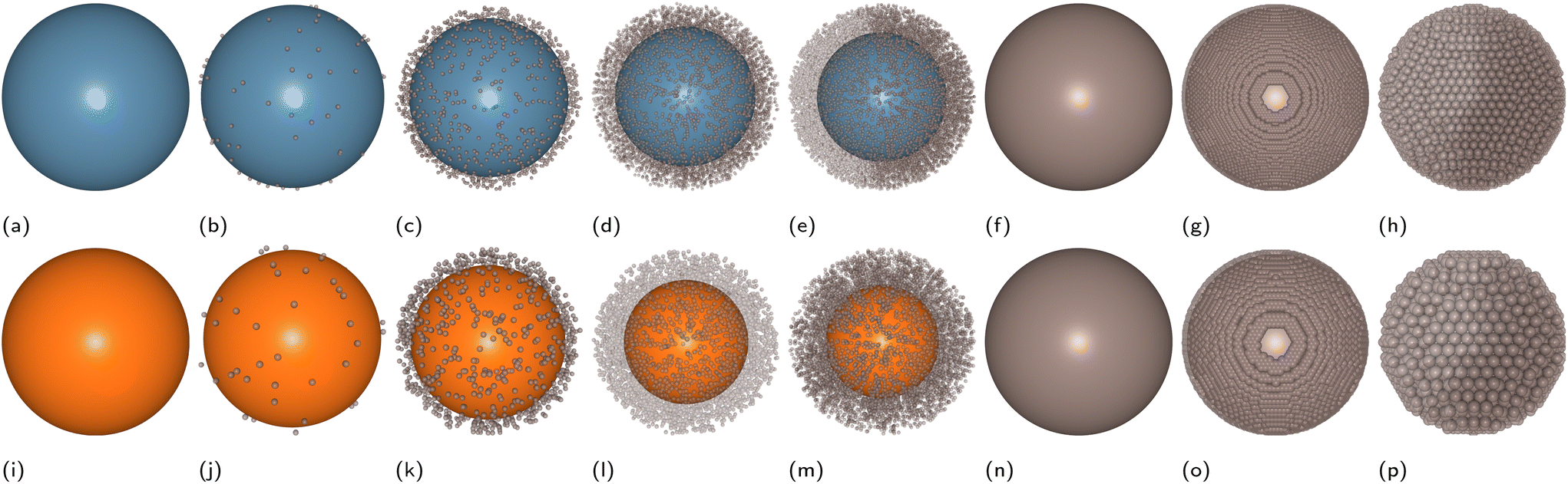
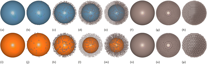 |
| | Fig. 4 CG structures of pristine and PEGylated AuNPs and AgNPs utilised in the UA calculations. Top row—CG models of AgNPs (a–h), bottom row – CG models of AuNPs (i–p). Naming convention of multiscale UA CG models, from left to right: pristine (a and i), mushroom (b and j), intermediate (c and k), brush (d and i), dense brush (e and m), shell–solid–all (f and n), shell–solid–raspberry (g and o), shell–raspberry–all (h and p). | |
The adsorption energies calculated with the UA model for BSA, TRG and ngTRF for the AuNPs and AgNPs are shown in Fig. 5 together with values found from experiment. The experimental values were evaluated from the reported binding constants KB:31 ΔGexp = RTlnKB. The uncoated R = 52.7 nm AgNPs exhibited stronger protein binding in comparison to R = 35.7 nm AuNPs. To determine if this was related to the material or size of the NP, additional calculations were performed for both materials over a range of radii and zeta potentials. The preference for binding to pristine AgNPs over pristine AuNPs in the model was found to be independent of the size of the core or the zeta potential in general (Fig. 6 and Fig. S9 in the ESI†): the adsorption was more exothermic for smaller sizes of NPs and did not change substantially for NPs with radii over 40–50 nm, with the energy either saturating as a function of the radius or becoming slightly less favourable. The predicted optimal radius for TRFs binding to pristine NPs was about 70 nm, while the optimal binding for BSA is predicted to occur for smaller NPs with radii under 40 nm.
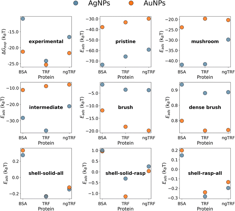 |
| | Fig. 5 Protein adsorption energies for pristine and PEGylated AuNPs and AgNPs. | |
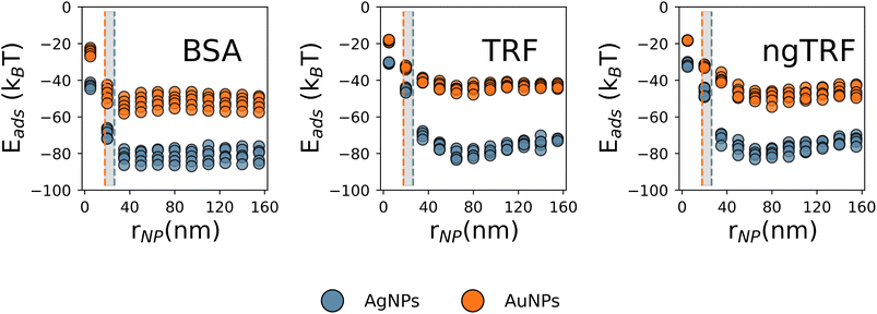 |
| | Fig. 6 The energy of adsorption for BSA and TRFs as a function of the radius of the NP. The experimental TEM radii for AgNPs (grey) and AuNPs (orange) are marked with vertical lines. Multiple points for the same radii value correspond to multiple zeta potential values. | |
The gradual PEGylation of NPs from the “pristine” to the “dense brush” states led to a significant decrease of the binding strength for all proteins. The predicted decrease of protein adsorption affinities due to the coating is a reflection of the stealth effect,15,61–63 which arises from the weaker binding of proteins to PEG and distance-dependant shielding of the metallic core by the shell. A comparison of the predicted binding energies with the experimental ones, both in dozens of kBT (Fig. 5), suggests that the proteins can partly penetrate the PEG layer and contact the metallic core of the NPs in the experimental systems.
In addition, the increase of the PEG grating density resulted in a reversal of the binding trend of pristine NPs: the binding to PEGAuNPs became more preferable as compared to PEGAgNPs. In our calculations for coated NPs, the increase in grafting density (and increase of the thickness/the decrease of metallic core radii) resulted in the preferred binding of larger (ca. 80 kDa) TRFs to smaller 35.7 nm PEGAuNPs in the high-density “brush” model, while binding of a lighter (ca. 66 kDa) BSA protein to larger 52.7 nm PEGAgNPs was less efficient. The calculated magnitude of the PEG stealth effect (difference between the PEGylated and pristine NP versions) for BSA was approximately 39kBT and 76kBT and for TRF 30kBT and 61kBT for AuNPs and AgNPs, respectively, suggesting that BSA experiences a stronger stealth effect in this case. Adsorption of TRF on PEGAuNPs was ca. 6kBT to 8kBT stronger as compared to PEGAgNPs (“brush” model). Similar conclusions on protein adsorption trends associated with the increase of PEG brush density can be also drawn from the orientation-specific adsorption energies for PEGAuNPs and PEGAgNPs shown as heatmaps in Fig. S10 and S11.† Thus, the interplay between the factors mentioned above (protein molecular weight, PEG grafting density, and NP radii and corresponding thickness of the polymer coating) ultimately results in changes in the protein adsorption affinities, which in the case of PEGylated gold NPs were found to be more significant for BSA than for TRFs. None of selected composite type models were able to match the experimental relative protein adsorption affinity. The “dense brush” model has shown the correct binding rankings, but the adsorption was predicted to be endothermic (Eads ≈ 0.8kBT to 0.9kBT). Surprisingly, the robust single-material (PEG) type “shell–solid–raspberry” model (Fig. 4, models g and o) predicted a correct ranking of the adsorption affinities and an overall exothermic binding. A one-bead-one-material “solid” model of the PEG outer layer, equivalent to the original single-component UA model,21,23,25,26 was able to reproduce the relative protein adsorption affinity rankings but did not differentiate between the types of core material (Fig. 5). The calculated absolute values of binding energies were endothermic for the adsorption of BSA and a small exothermic effect was predicted for adsorption of transferrins (Eads ≈ −0.1kBT to −0.2kBT). We attribute this to a limitation of the solid PEG NP model which does not allow for a sufficient number of interfacial contacts between smooth PEG surface, the metallic core and the rigid protein, which are obviously present in the composite models. These results suggest, that the shell morphology might be a defining factor for protein recognition for core–shell NPs, and the metallic core, screened from the direct interaction with the protein, provides further stabilisation. Furthermore, using a more detailed representation of the PEG–shell might be necessary to get a more accurate estimates for protein adsorption affinities.
To check the latter, adsorption on “custom” NPs models corresponding to different depth of PEGylation of AgNPs and AuNPs was also tested. The Fig. S2 in the ESI† shows that even at full grafting of PEG concentration (“custom-100%”), PEGAuNPs and PEGAgNPs would correspond to a different grafting models: the density of the PEG layer in PEGAgNPs is estimated to be higher than in PEGAuNPs. Thus, this difference might provide an additional explanation for stronger binding to PEGAuNPs as it was observed experimentally. The assumptions on polymer grafting densities used in our calculations were made based on limited experimental input and thus are subject to some arbitrariness. Thus, their simplicity might partially impact the overall conclusions. An additional information on the morphological features of the PEG coat expected to improve the performance of the UA method. From this perspective, we would like to stress out the importance of full reporting of physicochemical parameters/conditions used in the experiments with NPs,64 as these data could provide a better foundation for consistent theoretical models. As can be seen from the adsorption heatmaps (Fig. S10 and S11 in the ESI†) the preferred orientations of bound proteins for all considered models of NPs were similar across both core materials. In general, the increase of polymer grafting density did not qualitatively alter the protein adsorption fingerprint for either core material. However, with the increase of grafting densities some local minima disappeared and other became more pronounced. It should be also noted that in some cases multiple orientations corresponded to similar structures, as a result of symmetry of the protein 3D structures. The information from the UA output was used to reconstruct the CG coordinates of protein–NP complexes. Examples of such “nano-docked” structures for protein adsorption complexes corresponding to the most strongly bound configurations are shown in Fig. 7 and can illustrate the example of using the UA algorithm as a nano-docking tool, which can predict orientations of the immobilised protein on the NM surface and help to identify side-chains involved in the interaction with the NP. Since multiple local adsorption minima are present, multiple configurations characterised by a set of rotational angles and the energy ranking can be extracted during the post-analysis of obtained adsorption energies and used for further studies.
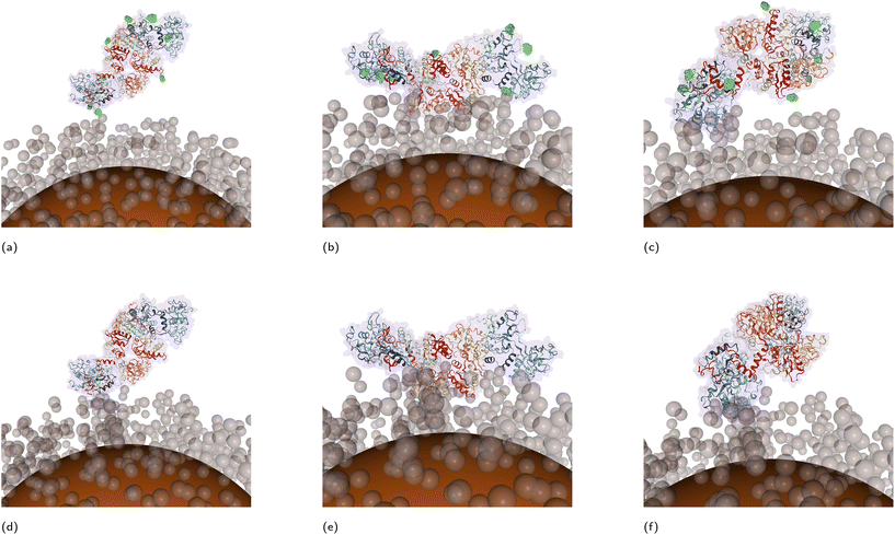 |
| | Fig. 7 CG structures of docked TRF (a–c) and ngTRF (d–f) proteins to PEGAuNP (“custom-50%” model) reconstructed from UA output. Top row – TRF, bottom row – ngTRF. Approximate rotational coordinates from left to right: (ϕ = 180°; θ = 90°), (ϕ = 200°; θ = 25°) and (ϕ = 320°; a = 125°). | |
3.3. Impact of glycosylation state of transferrin on adsorption affinities
As mentioned above, the predictions of the UA model were sensitive to the presence of post-translational modifications in the protein, e.g. glycosides in TRF vs. the absence of those in ngTRF. This sensitivity was dependent on the modelling resolution of PEG brush density and the ability of glycosylated side-chains to make a contact with NP core or shell beads. For the low-density brush models, the interaction of glycosylated TRF was predicted stronger than that for the non-glycosylated variant. This overall elevated binding affinity of glycosylated TRF at low grafting densities can be explained by an additional effect associated with stronger binding calculated for Ag and Au slabs and individual glycan fragments (see previously reported Ag values in work26 and Fig. S6 for Au values in ESI†). For example, for Au FCC (111), which is the main surface in the Wulff construction, the adsorption energies for carbohydrates were ca. −21kBT to −24kBT while for the majority of SCAs the adsorption energies were less than −20kBT. At the same time, the interaction of individual glycan fragments with a PEG trimer was even weaker than PEG–AA interaction (at ca. −0.4kBT, Fig. S8 in ESI†). As the energy estimate by the UA method includes contributions from all rotational/translational configurations (including statistically less relevant penalised orientations with close contacts between glycans and metallic/PEG CG beads), these extra contributions can lead to an increased Eads term for glycosylated proteins. Furthermore, for NPs with less dense PEG layer and more accessible metallic core for metal–glycan contact, this added stabilisation will be stronger. From this, it can be also concluded that proteins with a greater fraction of glycosylated residues available for the interactions with the NP are expected to show a stronger binding to the Ag or Au surfaces. The increase of PEG grafting density (“dense brush”) led to almost equal adsorption of TRF and ngTRF. The slightly favored binding of glycosylated TRF to very dense PEG brushes can be linked to the synergy between the hydrophilic nature of PEG and carbohydrate fragments. Thus, for TRF, which contains only a small number (8 in total) of N-glycan fragments, glycosylation-assisted binding onto coated NPs with 3–8 nm thick PEG layer is not expected to be crucial. Instead, it is more likely that the cooperative interaction of SCAs with the NP controls the total protein adsorption affinity. The reported experimental data31 on binding constants for transferrins immobilised at other functionalised AuNPs/AgNPs partially (subject to differences in size, shape, surface charges, etc. for studied NPs) supports this prediction: non-glycosylated ngTRF was shown in general to have a stronger interaction as compared to its glycosylated version.
The arrangement of adsorption complexes of transferrin variants immobilised on modelled NPs reconstructed from the UA output also supports this hypothesis (Fig. 7). Three common lowest energy configurations of immobilised transferrins were identified at the regions with coordinates (ϕ = 180°; θ = 90°), (ϕ = 200°; θ = 25°) and (ϕ = 320°; θ = 125°). In these orientations, only two to three N-linked glycan fragments were in proximity of the NP surface (Fig. 7, glycan fragments highlighted in green), while the remaining five to six glycans were directed outwards. This suggests that glycans, commonly residing at the protein exterior, should remain available for secondary interactions after the adsorption onto a NP. A similar behavior was observed experimentally for the formation of protein corona on citrate-stabilised gold NPs where glycosylated fragments of adsorbed proteins remained accessible for further modifications.65
In summary, we have observed that PEG coating as implemented in this updated model changes the protein adsorption on NPs in several aspects. Most of all, it reduces the binding by shielding the metallic core from direct interactions, causing the stealth effect. By comparing the computed and experimental adsorption energies, we were able to judge about the actual density and quality of the PEG coating on AuNPs and AgNPs, which in the specific experiment appeared to be imperfect. Secondly, it changes the relative binding affinity ranking, such that we calculate different binding preferences for different proteins at different PEG grafting densities. Ultimately, this will affect the protein corona composition via the complex interplay of multiple factors,62e.g. grafting density and molecular weight of the grafted polymers, protein type, and its glycosylation state. The latter should enhance the overall interaction of the proteins with PEGylated and pristine noble metal NPs. This observation suggests that glycans, and possibly other protein modifiers (e.g., lipid fragments in lipoproteins), should be taken into account for modeling bio-nano interfaces existing in physiological conditions. Potentially, glycosylation-assisted protein adsorption may be used as a strategy to develop sensitive analytical nanoplatforms for detecting blood protein markers in diabetic patients66 or viruses containing glycan-rich patches on their exterior.67 The predicted stronger overall adsorption of glycosylated proteins onto uncoated and coated NPs also leads to questions about how metabolic syndromes68 can impact the efficiency of nanomedicine in patients as a result of potentially altered bioaccumulation of NPs and associated adverse outcomes linked to such changes.
4. Conclusions
We performed a multiscale computational study of protein binding onto PEG-functionalised AuNPs and AgNPs. For this purpose, we have introduced a new modular CG model of coated or multicomponent NPs, which is capable of representing a variety of typical core–shell structures used for biomedical nanoplatforms. The predictions of protein affinity rankings are in line with available experimental data. Moreover, based on comparisons with experimental data, we were able to obtain molecular level insights into the structure of the polymer coat and preferred protein orientation that are not accessible experimentally. As the calculations with this multiscale approach are very fast once the nanomaterials and interactions are parameterised, this method can be used for a high throughput in silico pre-screening of protein adsorption onto core–shell NPs for the rational design of drug nanocarriers and nanobiosensors.69,70 While qualitative predictions of protein adsorption can be obtained already with a uniform density representation of the NP, a more detailed representation of core–shell noble metal NPs including the molecular structure of the coating is necessary for more accurate investigations into protein corona content and bound protein activities. Provided raspberry models of the NPs can be applied to study nanocarriers of high structural complexity (e.g. decorated NPs, doped NPs, nanocomposites, etc.). The reported protocol can be used as a core module for optimisation of protein binding simultaneously as a function of shell morphology, NP size and charge, core and shell material type, and protein composition, which can be done programmatically and by combining with machine-learning techniques. The CG structures of docked protein–NP complexes obtained using our model can be used as initial estimate coordinates for further computational refinement, aiding in the precise design of drug nanocarriers, nanoenzymes, and nanobiosensors where the information on the orientation of the immobilised protein is important.
List of acronyms
The following acronyms were used in the text of manuscript:
|
n
CG
| Number of CG beads |
| 10K | PEG with molecular weight 10000 g mol−1 |
| 30K | PEG with molecular weight 30000 g mol−1 |
| 5K | PEG with molecular weight 5000 g mol−1 |
| AA | Amino acid |
| AWT-MetaD | Adaptive well-tempered metadynamics |
| CD | Circular dichroism |
| CG | Coarse-grained |
| FCC | Face-centered cubic |
| MD | Molecular dynamics |
| NC | Nanocarrier |
| NP | Nanoparticle |
| PEG | Polyethylene glycol |
| PEGAgNP | PEGylated Ag nanoparticle |
| PEGAuNP | PEGylated Au nanoparticle |
| PMF | Potential of mean force |
| SCA | Side chain analogues |
| UA | UnitedAtom |
| VdW | van der Waals |
Author contributions
Julia Subbotina: Conceptualisation, methodology, software, visualisation, validation, formal analysis, investigation, resources, writing – original draft preparation. Ian Rouse: Conceptualisation, methodology, software, data curation, writing – review editing. Vladimir Lobaskin: Funding acquisition, conceptualisation, methodology, writing – review editing.
Conflicts of interest
There are no conflicts to declare.
Acknowledgements
This work was supported by Science Foundation of Ireland grant, 16/IA/4506 “Quantitative Modelling of Bionano Interface” and EU Horizon 2020 grant NanoSolveIT, grant agreement 814572. The authors also would like to acknowledge the Irish Centre for High-End Computing (ICHEC) and the ResearchIT Sonic cluster, which was funded by UCD IT Services and the Research Office, for the provision of computational facilities and support.
References
- B. Klębowski, J. Depciuch, M. Parlińska-Wojtan and J. Baran, Int. J. Mol. Sci., 2018, 19, 4031 CrossRef PubMed.
- J. Xu, C. Peng, M. Yu and J. Zheng, WIREs Nanomed. Nanobiotechnol., 2017, 9, e1453 CrossRef PubMed.
- M. Rai, A. P. Ingle, S. Birla, A. Yadav and C. A. D. Santos, Crit. Rev. Microbiol., 2015, 1–24 CrossRef PubMed.
- J. Conde, G. Doria and P. Baptista, J. Drug Delivery, 2012, 2012, 1–12 CrossRef PubMed.
- S. Attarilar, J. Yang, M. Ebrahimi, Q. Wang, J. Liu, Y. Tang and J. Yang, Front. Bioeng. Biotechnol., 2020, 8, 822 CrossRef PubMed.
- V. Chandrakala, V. Aruna and G. Angajala, Emergent Mater., 2022, 5, 1593–1615 CrossRef CAS PubMed.
- M. P. Monopoli, C. Åberg, A. Salvati and K. A. Dawson, Nat. Nanotechnol., 2012, 7, 779–786 CrossRef CAS PubMed.
- N. Durán, C. P. Silveira, M. Durán and D. S. T. Martinez, J. Nanobiotechnol., 2015, 13, 55 CrossRef PubMed.
- J. L. Perry, K. G. Reuter, M. P. Kai, K. P. Herlihy, S. W. Jones, J. C. Luft, M. Napier, J. E. Bear and J. M. DeSimone, Nano Lett., 2012, 12, 5304–5310 CrossRef CAS PubMed.
- V. C. F. Mosqueira, P. Legrand, J.-L. Morgat, M. Vert, E. Mysiakine, R. Gref, J.-P. Devissaguet and G. Barratt, Pharm. Res., 2001, 18, 1411–1419 CrossRef CAS PubMed.
- G. Chen, I. Roy, C. Yang and P. N. Prasad, Chem. Rev., 2016, 116, 2826–2885 CrossRef CAS PubMed.
- S. M. G. Hayat, V. Bianconi, M. Pirro and A. Sahebkar, Int. J. Pharm., 2019, 569, 118628 CrossRef PubMed.
- J. S. Suk, Q. Xu, N. Kim, J. Hanes and L. M. Ensign, Adv. Drug Delivery Rev., 2016, 99, 28–51 CrossRef CAS PubMed.
- R. Gref, M. Lück, P. Quellec, M. Marchand, E. Dellacherie, S. Harnisch, T. Blunk and R. Müller, Colloids Surf., B, 2000, 18, 301–313 CrossRef CAS PubMed.
- M. Li, S. Jiang, J. Simon, D. Paßlick, M.-L. Frey, M. Wagner, V. Mailänder, D. Crespy and K. Landfester, Nano Lett., 2021, 21, 1591–1598 CrossRef CAS PubMed.
- Z. Cournia, B. Allen and W. Sherman, J. Chem. Inf. Model., 2017, 57, 2911–2937 CrossRef CAS PubMed.
- E. Duboué-Dijon and J. Hénin, J. Chem. Phys., 2021, 154, 204101 CrossRef PubMed.
- T. R. Walsh, Acc. Chem. Res., 2017, 50, 1617–1624 CrossRef CAS PubMed.
- R. A. Latour, Colloids Surf., B, 2020, 191, 110992 CrossRef CAS PubMed.
- I. L. Geada, H. Ramezani-Dakhel, T. Jamil, M. Sulpizi and H. Heinz, Nat. Commun., 2018, 9, 716 CrossRef PubMed.
- D. Power, I. Rouse, S. Poggio, E. Brandt, H. Lopez, A. Lyubartsev and V. Lobaskin, Modell. Simul. Mater. Sci. Eng., 2019, 27, 084003 CrossRef CAS.
- H. Lopez and V. Lobaskin, J. Chem. Phys., 2015, 143, 243138 CrossRef PubMed.
-
H. Lopez, E. G. Brandt, A. Mirzoev, D. Zhurkin, A. Lyubartsev and V. Lobaskin, Advances in Experimental Medicine and Biology, Springer International Publishing, 2017, pp. 173–206 Search PubMed.
- M. Saeedimasine, E. G. Brandt and A. P. Lyubartsev, J. Phys. Chem. B, 2020, 125, 416–430 CrossRef PubMed.
- I. Rouse, D. Power, E. G. Brandt, M. Schneemilch, K. Kotsis, N. Quirke, A. P. Lyubartsev and V. Lobaskin, Phys. Chem. Chem. Phys., 2021, 23, 13473–13482 RSC.
- J. Subbotina and V. Lobaskin, J. Phys. Chem. B, 2022, 126, 1301–1314 CrossRef CAS PubMed.
- I. Hasenkopf, R. Mills-Goodlet, L. Johnson, I. Rouse, M. Geppert, A. Duschl, D. Maier, V. Lobaskin, I. Lynch and M. Himly, Nano Today, 2022, 46, 101561 CrossRef CAS.
- P. Mosaddeghi Amini, J. Subbotina and V. Lobaskin, Nanomaterials, 2023, 13, 1857 CrossRef PubMed.
- M. Bonomi, D. Branduardi, G. Bussi, C. Camilloni, D. Provasi, P. Raiteri, D. Donadio, F. Marinelli, F. Pietrucci, R. A. Broglia and M. Parrinello, Comput. Phys. Commun., 2009, 180, 1961–1972 CrossRef CAS.
- E. G. Brandt and A. P. Lyubartsev, J. Phys. Chem. C, 2015, 119, 18126–18139 CrossRef CAS.
- R. Barbir, R. R. Jiménez, R. Martín-Rapún, V. Strasser, D. D. Jurašin, S. Dabelić, J. M. de la Fuente and I. V. Vrček, ACS Appl. Mater. Interfaces, 2021, 13, 27533–27547 CrossRef CAS PubMed.
- Y. R. Perera, J. X. Xu, D. L. Amarasekara, A. C. Hughes, I. Abbood and N. C. Fitzkee, Molecules, 2021, 26, 5788 CrossRef CAS PubMed.
-
P. J. Flory, Principles of Polymer Chemistry, Cornell University Press, Ithaca, NY, 1953 Search PubMed.
- Q. Huang, I. Yoon, J. Villanueva, K. Kim and D. J. Sirbuly, Soft Matter, 2014, 10, 8001–8010 RSC.
- Z. Ma, D. N. LeBard, S. M. Loverde, K. A. Sharp, M. L. Klein, D. E. Discher and T. H. Finkel, PLoS One, 2014, 9, 1–10 Search PubMed.
-
Bitbucket page for UA code
https://bitbucket.org/softmattergroup
.
-
mp-81: Au (cubic, Fm-3m, 225)
https://materialsproject.org/materials/mp-81
.
-
mp-124: Ag (cubic, Fm-3m, 225)
https://materialsproject.org/materials/mp-124
.
- S. A. Alsharif, D. Power, I. Rouse and V. Lobaskin, Nanomaterials, 2020, 10, 1967 CrossRef CAS PubMed.
- A. Barducci, G. Bussi and M. Parrinello, Phys. Rev. Lett., 2008, 100, 020603 CrossRef PubMed.
- S. Pronk, S. Páll, R. Schulz, P. Larsson, P. Bjelkmar, R. Apostolov, M. R. Shirts, J. C. Smith, P. M. Kasson, D. van der Spoel, B. Hess and E. Lindahl, Bioinformatics, 2013, 29, 845–854 CrossRef CAS PubMed.
- T.-J. Lin and H. Heinz, J. Phys. Chem. C, 2016, 120, 4975–4992 CrossRef CAS.
- K. Kanhaiya, S. Kim, W. Im and H. Heinz, npj Comput. Mater., 2021, 7, 17 CrossRef CAS.
- J. Huang, S. Rauscher, G. Nawrocki, T. Ran, M. Feig, B. L. de Groot, H. Grubmüller and A. D. MacKerell, Nat. Methods, 2016, 14, 71–73 CrossRef PubMed.
- S. Jo, T. Kim, V. G. Iyer and W. Im, J. Comput. Chem., 2008, 29, 1859–1865 CrossRef CAS PubMed.
-
J. Subbotina, United Atom Parameters for United Atom Multiscale Modelling Of Bio-Nano Interactions Of Zero-Valent Gold Nanoparticles, 2022, https://zenodo.org/record/6066434 Search PubMed.
-
Y. Subbotina, United Atom Parameters for United Atom Multiscale Modelling Of Bio-Nano Interactions Of Zero-Valent Silver Nanoparticles, 2022, https://zenodo.org/record/5846080 Search PubMed.
- M. J. Sippl, M. Ortner, M. Jaritz, P. Lackner and H. Flöckner, Folding Des., 1996, 1, 289–298 CrossRef CAS PubMed.
-
J. Subbotina, United Atom Parameters for United Atom Multiscale Modelling Of Bio-Nano Interactions Of PEG Coated Nanoparticles, 2022, https://zenodo.org/record/6066503 Search PubMed.
- T. S. Ulmer, B. E. Ramirez, F. Delaglio and A. Bax, J. Am. Chem. Soc., 2003, 125(30), 9179–9191 CrossRef CAS PubMed.
- K. A. Majorek, P. J. Porebski, A. Dayal, M. D. Zimmerman, K. Jablonska, A. J. Stewart, M. Chruszcz and W. Minor, Mol. Immunol., 2012, 52, 182 CrossRef PubMed.
- J. Wally, P. J. Halbrooks, C. Vonrhein, M. A. Rould, S. J. Everse, A. B. Mason and S. K. Buchanan, J. Biol. Chem., 2006, 281, 24934–24944 CrossRef CAS PubMed.
- E. Jurrus, D. Engel, K. Star, K. Monson, J. Brandi, L. E. Felberg, D. H. Brookes, L. Wilson, J. Chen, K. Liles, M. Chun, P. Li, D. W. Gohara, T. Dolinsky, R. Konecny, D. R. Koes, J. E. Nielsen, T. Head-Gordon, W. Geng, R. Krasny, G.-W. Wei, M. J. Holst, J. A. McCammon and N. A. Baker, Protein Sci., 2017, 27, 112–128 CrossRef PubMed.
- H. Nguyen, D. A. Case and A. S. Rose, Bioinformatics, 2017, 34, 1241–1242 CrossRef PubMed.
- D. R. Hristov, H. Lopez, Y. Ortin, K. O'Sullivan, K. A. Dawson and D. F. Brougham, Nanoscale, 2021, 13, 5344–5355 RSC.
- M. Malmsten, K. Emoto and J. M. V. Alstine, J. Colloid Interface Sci., 1998, 202, 507–517 CrossRef CAS.
- S. Moghimi and J. Szebeni, Prog. Lipid Res., 2003, 42, 463–478 CrossRef CAS PubMed.
- M. Sun, J. Deng, Z. Tang, J. Wu, D. Li, H. Chen and C. Gao, Colloids Surf., B, 2014, 122, 134–142 CrossRef CAS PubMed.
- S. M. Bhattacharjee, A. Giacometti and A. Maritan, J. Phys.: Condens. Matter, 2013, 25, 503101 CrossRef PubMed.
- P. G. de Gennes, Macromolecules, 1980, 13, 1069–1075 CrossRef CAS.
- S. Schöttler, G. Becker, S. Winzen, T. Steinbach, K. Mohr, K. Landfester, V. Mailänder and F. R. Wurm, Nat. Nanotechnol., 2016, 11, 372–377 CrossRef PubMed.
- C. D. Walkey, J. B. Olsen, H. Guo, A. Emili and W. C. W. Chan, J. Am. Chem. Soc., 2012, 134, 2139–2147 CrossRef CAS PubMed.
- J. S. Suk, Q. Xu, N. Kim, J. Hanes and L. M. Ensign, Adv. Drug Delivery Rev., 2016, 99, 28–51 CrossRef CAS PubMed.
- M. Faria, M. Björnmalm, K. J. Thurecht, S. J. Kent, R. G. Parton, M. Kavallaris, A. P. R. Johnston, J. J. Gooding, S. R. Corrie, B. J. Boyd, P. Thordarson, A. K. Whittaker, M. M. Stevens, C. A. Prestidge, C. J. H. Porter, W. J. Parak, T. P. Davis, E. J. Crampin and F. Caruso, Nat. Nanotechnol., 2018, 13, 777–785 CrossRef CAS PubMed.
- E. Clemente, M. Martinez-Moro, D. N. Trinh, M. G. Soliman, D. I. R. Spencer, R. A. Gardner, M. Kotsias, A. S. Iglesias, S. Moya and M. P. Monopoli, J. Colloid Interface Sci., 2022, 613, 563–574 CrossRef CAS PubMed.
- M. Ardawi, H. Nasrat, S. Mira and H. Fatani, Diabetic Med., 1990, 7, 819–824 CrossRef CAS PubMed.
- B. O'Callahan, O. Qafoku, V. Balema, O. A. Negrete, A. Passian, M. H. Engelhard and K. M. Waters, Langmuir, 2021, 37, 12089–12097 CrossRef PubMed.
-
M. K. Danquah and J. Jeevanandam, Emerging Nanomedicines for Diabetes Mellitus Theranostics, Elsevier, 2022, pp. 173–198 Search PubMed.
- D. N. Trinh, R. A. Gardner, A. N. Franciosi, C. McCarthy, M. P. Keane, M. G. Soliman, J. S. O'Donnell, P. Meleady, D. I. R. Spencer and M. P. Monopoli, ACS Nano, 2022, 16, 5463–5475 CrossRef CAS PubMed.
- S. Wan, P. M. Kelly, E. Mahon, H. Stöckmann, P. M. Rudd, F. Caruso, K. A. Dawson, Y. Yan and M. P. Monopoli, ACS Nano, 2015, 9, 2157–2166 CrossRef CAS PubMed.
|
| This journal is © The Royal Society of Chemistry 2023 |
Click here to see how this site uses Cookies. View our privacy policy here. 
 Open Access Article
 This Open Access Article is licensed under a Creative Commons Attribution-Non Commercial 3.0 Unported Licence
 *,
Ian
Rouse
*,
Ian
Rouse