
 Open Access Article
 This Open Access Article is licensed under a
 Creative Commons Attribution 3.0 Unported Licence
Mechanical properties of TiO2/carboxylic-acid interfaces from first-principles calculations†
Kai
Sellschopp‡
 and
Gregor B.
Vonbun-Feldbauer
*
and
Gregor B.
Vonbun-Feldbauer
*
Institute of Advanced Ceramics, Hamburg University of Technology, Denickestr. 15, 21073 Hamburg, Hamburg, Germany. E-mail: gregor.feldbauer@tuhh.de
First published on 12th October 2023
Abstract
Nature forms structurally complex materials with a large variation of mechanical and physical properties from only very few organic compounds and minerals. Nanocomposites made from TiO2 and carboxylic-acids, two substances that are available to nature as well as materials engineers, can be seen as representative of a huge class of natural and bio-inspired materials. The hybrid interfaces between the two components are thought to determine the overall properties of the composite. Yet, little is known about the atomistic processes at those interfaces under load and their failure mechanisms. The present work models the stress–strain curves of TiO2/carboxylic-acid interfaces in the slow deformation limit for different facets and binding modes, employing density functional theory calculations. Contrary to former hypotheses, the interface rarely fails through a de-bonding of the molecule, but rather through a surface failure mechanism. Furthermore, a stress-release mechanism is discovered for the bi-dentate binding mode on the {101} facet. Deriving mechanical properties, such as the interface strength, strain at interface failure, and the elastic modulus, allows a comparison with experimental results. The calculated strengths and elastic moduli already agree qualitatively with properties of nanocomposites, despite the simplifications in the model consisting of periodic sandwich structures. The results presented here will help to improve these materials and can be directly integrated in multi-scale simulations, in order to reach a more accurate quantitative description.
1 Introduction
Over the course of several millions of years of evolution, nature was able to develop hierarchical nanocomposite materials from only very few ingredients that combine high strength and fracture toughness1 – a combination that is usually not found in human-made materials. Despite the significant progress that has been made in the past years, it remains challenging to mimic the hierarchical structure through materials engineering. The overall goal would be to outperform natural materials, such as enamel2 or nacre,3 by combining materials that are not available in nature. This further allows to combine the improved mechanical properties with additional functionality, such as tailored electrical conductivity, magnetism, or optical properties.4,5Due to their similarity with natural ingredients, many bio-inspired hierarchical nanocomposites are composed of transition-metal–oxide (TMO) nanoparticles and carboxylic acids (CAs) that interlink the particles. The small size of the nanoparticles, and the resulting huge interface-to-volume ratio, make the interface between those two phases the most important lever for influencing the properties of the lowest level of hierarchy.6 In fact, one route for optimising the mechanical properties of nanocomposites is to replace the anchoring group to increase the binding strength at the interface or even modify the particles’ surfaces.7,8
Since TMO-CA interfaces are also relevant for other applications, such as (photo-)catalysis,9 waste-water cleaning,10 and targeted drug-delivery,11 there is plenty of research studying the binding modes and energies in this class of interfaces. However, little is known about how the interface reacts to mechanical loading. The general assumption is that the binding energy is the determining factor for the strength of the interface. Therefore, molecules that bind more strongly to the TMO are expected to improve the strength of the material while maintaining a certain fracture toughness. Nonetheless, a recent experimental study found that this assumption is not valid for replacing the CA anchoring group with a phosphonic or phosphoric acid anchoring group.8 Hence, in order to gain a deeper understanding of the relevant factors, it is worth taking a closer look at the atomic processes at the interface.
In this work, the response of different interfaces between anatase titania (TiO2) nanoparticles and CAs to mechanical loading are studied with ab initio calculations based on density functional theory (DFT). Titania and CAs both appear in natural as well as in engineered materials. Accordingly, TiO2-CA nanocomposites are a great reference system for gaining insights into the atomic processes underlying the mechanical properties of a wide range of natural and bio-inspired materials. Anatase TiO2 is the most stable titania modification in nanoparticles due to the low surface energy of its {101}, {001}, and {100} facets.12 Furthermore, the shape of the nanoparticles can be controlled through surface modifications,13–15 impacting their photocatalytic activity16,17 and the mechanical properties of titania-CA nanocomposites.18 Therefore, understanding the mechanical response of the interface at the atomic scale will also facilitate using this degree of freedom for engineering TiO2-CA and similar nanocomposite materials. In order to achieve these goals, the stress–strain curves are calculated for interface models representing the most important facets and binding modes, and the mechanical properties of the interface, such as the strength, the strain at failure, and the elastic modulus are derived from the stress–strain curves. Additionally, the stiffness of the CA linker molecule is varied through an introduction of a C![[double bond, length as m-dash]](https://www.rsc.org/images/entities/char_e001.gif) C double bond to study its influence on the overall mechanical response.
C double bond to study its influence on the overall mechanical response.
2 Computational details
2.1 Modelling interface stress
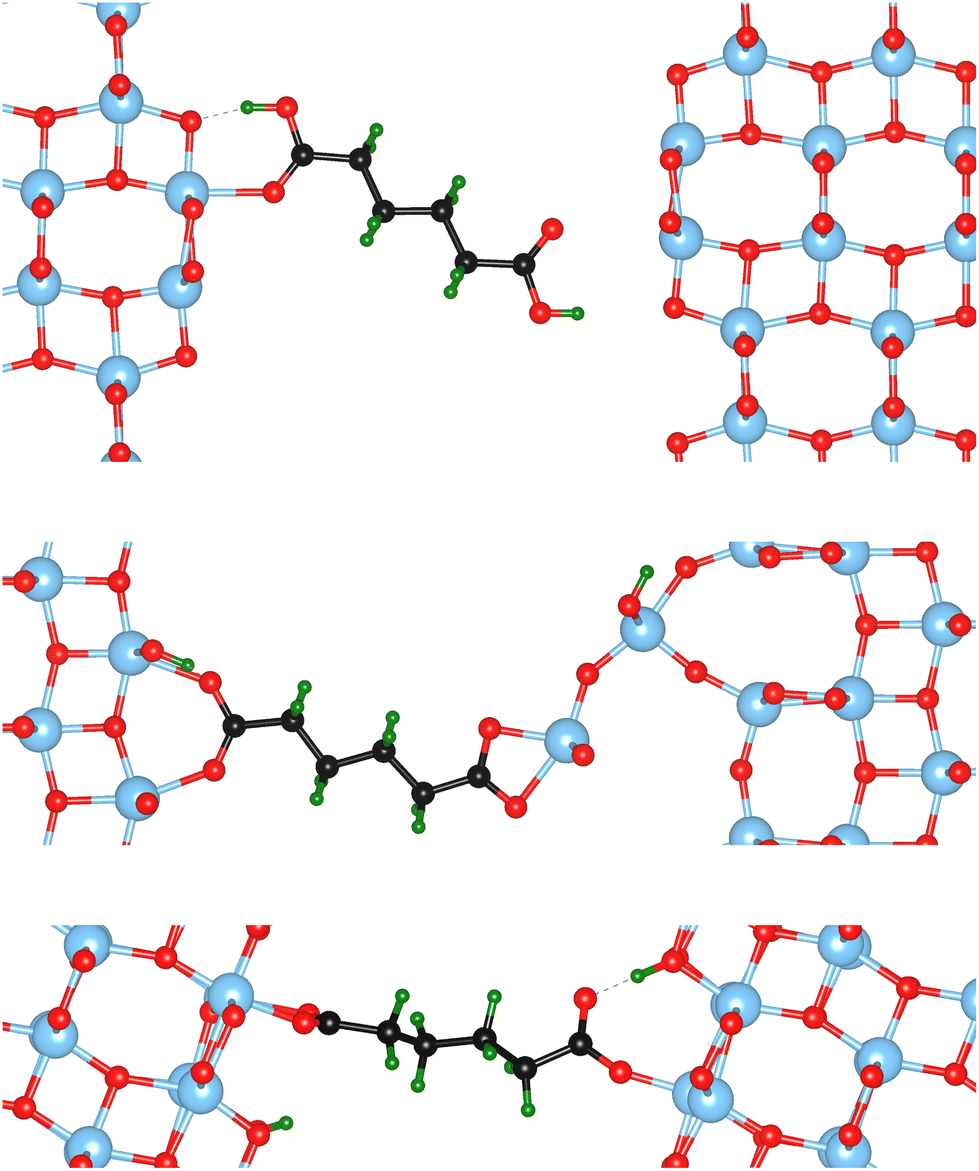
Nine different model systems are studied in this work. In each model, a dicarboxylic acid molecule with a chain of six carbon atoms connects two surface slabs of one of the three most relevant facets {101}, {001}, and {100}. Based on our prior studies,15,19,20 and similar results from other groups,21–25 the bi-dentate (bd) and mono-dentate (md) adsorption modes are considered. Two modifications of the carboxylic acid, one with only C–C single bonds (sb) and one with a CC double bond (db) in the center of the molecule, are studied for the mono-dentate adsorption mode to analyse whether a change in stiffness of the molecular backbone influences the mechanical properties of the interface. In total, the combination of the three facets (named by their indices {hkl}) with the three different molecular connectors result in nine models, which will be named {hkl}-bd, {hkl}-md-sb, {hkl}-md-db according to the abbreviations introduced before. As an example, the starting structures for the three different molecular connectors are illustrated in Fig. 1 for the {100} facet, while the remaining six initial models are visualised in the ESI.†
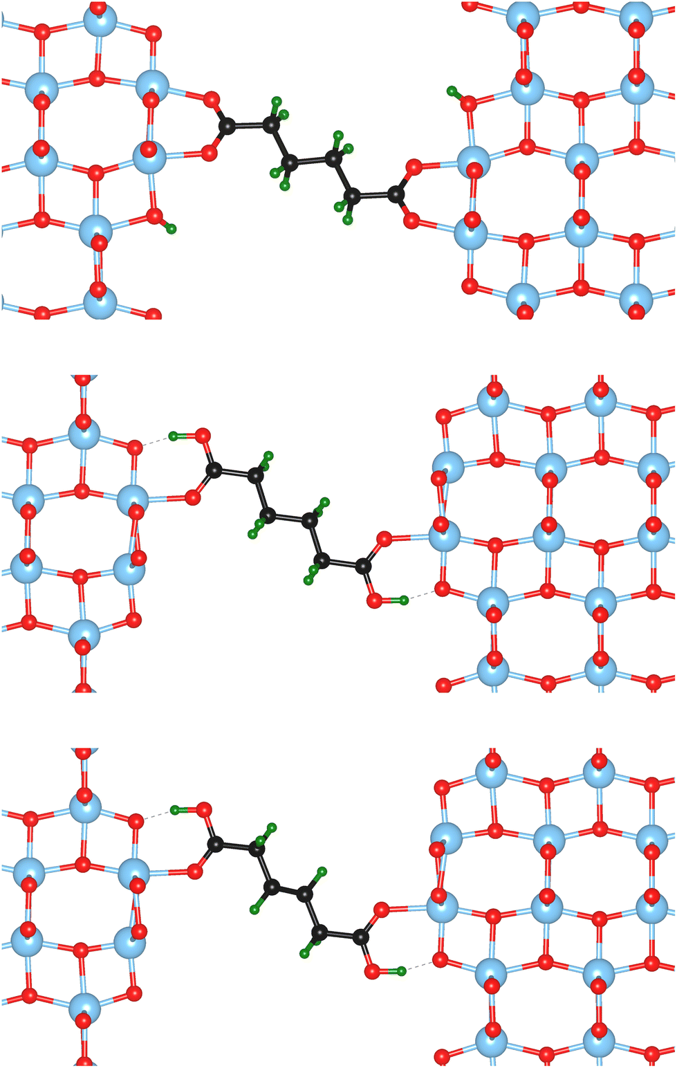 | ||
| Fig. 1 Starting structures of the different anatase TiO2 {100} – carboxylic acid interfaces, illustrating the linker models studied in this work. Top to bottom: bi-dentate binding (bd), mono-dentate binding (md-sb), and mono-dentate binding with a double bond in the center of the molecule (md-db). Color code: Ti – blue, O – red, C – black, H – green. | ||
Following the “constrained geometries simulate external forces” (COGEF) approach introduced by Beyer26 and described very well in a review by Stauch and Dreuw,27 the outer two layers of the surface slabs are fixed in their bulk positions. Changing the relative positions of the fixed layers of the two surface slabs, while allowing relaxations of all other atoms, changes the forces acting on the atoms in the fixed layers. However, these atoms will be subjected to forces even when the interface is free of stress, because of the bulk structure constraint. Therefore, the force F acting on the interface, consisting of the relaxed surface layers and the connecting molecule, is defined with respect to the forces on these atoms in a relaxed, clean, asymmetric surface slab model F0:
 | (1) |
Before exerting stress on the interface, the relative position of the two surface slabs is optimised with a conjugate gradient algorithm to minimise the force on the interface to less than 10 meV Å−1, producing the relaxed interface structures shown in Fig. 1 and the ESI.† Then, the top layer is displaced step-wise (with a step width of 0.1 Å) in positive and negative z-direction, i.e. perpendicular to the interface, to induce tensile and compressive strain and stress, respectively. The displacement value should be chosen carefully, since too large values might yield computational artefacts. The value of 0.1 Å was found here and in previous studies, e.g.28 for Al/TiN interfaces, to be a reliable choice. In the tensile region, this procedure is continued until the interface fails, which is automatically detected from a significant drop in the force. Only a few points are recorded in the compressive regime, corresponding to an elastic deformation. Fig. 2 illustrates this approach for modelling the mechanical properties of interfaces at the atomic scale.
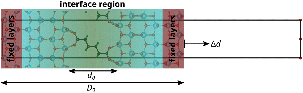 | ||
| Fig. 2 Slab model for calculating mechanical properties of interfaces. The outer slab layers are fixed in their relative positions, while the interface region is fully relaxed. Displacing the fixed layers step-wise (Δd) applies stress to the interface (COGEF method). The interphase strain is calculated with respect to the initial length d0 (see Results and discussion). | ||
Additionally, it should be noted that the small step size combined with the relaxation of all unconstrained atoms at each step in this modelling approach corresponds to the limit of infinitely slow deformation at 0K. Finite temperature effects and faster deformation rates can significantly alter the strength, stiffness, and plasticity of a material. On the other hand, most mechanical tests are performed at slow deformation rates as well, and other atomistic modelling approaches that include the effect of deformation rate and temperature, such as molecular dynamics, are often limited to unrealistically high deformation rates.
2.2 Energy and force calculation
Energies and forces are calculated with DFT as implemented in the Vienna Ab initio Simulation Package (VASP, version 5.4.4).29–32 VASP uses periodic boundary conditions and the projector augmented-wave method33 was used in all calculations. All calculations presented here were performed non-spin-polarised for efficiency reasons, since tests on various model systems used in this work, in their unstressed and deformed states, and starting from different initial magnetic moments, all failed to show a non-zero final magnetisation. The exchange–correlation functional is described on the level of the generalized gradient approximation using the PBE parametrization.34 Van der Waals (vdw) interactions are not treated here since the investigated systems are considered to be dominated by chemical bonds and the distances between the molecules are rather large. To probe this assumption, to investigate the effect of vdW interactions in our current systems, and for better comparison with future studies, DFT calculations with the PBE functional including the D3-vdW-correction35 for two typical systems, namely the configurations {001}-bd and {100}-md-sb were performed. Those systems involve different surface facets and they exhibit two different failure mechanisms under tensile stress as it will be demonstrated in the following “Results” section. For the mechanical properties like strength and elastic moduli mostly similar results were obtained only showing deviations typical for using different XC functionals. Importantly, the failure mechanisms under tensile stress are not significantly affected. The type of failure for the two interfaces is maintained and only the tensile strains at failure are slightly increased using the vdW correction. Larger deviations for the mechanical properties occur under compressive stress probably because of the shrinking interphase space and the sensitivity of those properties towards the orientation of the linker molecule. The main focus of this study is however the tensile regime. The results of the calculations including vdW corrections are presented in the ESI, see Fig. S7 and Table S1.† For systems with dominating physical bonds and higher molecular densities van der Waals corrections should be more critical and thus they should be included.20 An energy cutoff of 520 eV was employed. k-point grids of 7 × 5 × 1 for {001} systems and 7 × 3 × 1 for {101} and {100} systems account for the different lengths of the lattice vectors. Atomic positions were optimized with the conjugate-gradient algorithm until the forces on unconstrained atoms became smaller than 5 meV Å−1. Bader charge analyses were performed using the implementation of Henkelman et al.36–383 Results and discussion
The atomic scale response to mechanical strain on different TiO2-carboxylic-acid interfaces is modelled in the quasi-static approximation using the ab initio methods described in the computational details. In the tensile regime the interface is strained up to the point of failure, while only a small range of points are modelled in the compressive regime. As a first step for analysing the results, the calculated energies and forces are plotted versus the displacement in the direction perpendicular to the interface (z-direction) as shown in Fig. 3 and 4. All the interfaces studied here, exhibit a mostly linear relation between force and displacement, even for large deformations, leading to a parabolic shape of the energy-versus-displacement curve. Only for displacements close to the point of failure in the tensile region, the force deviates from the linear relationship, indicating a transition from elastic to plastic deformation.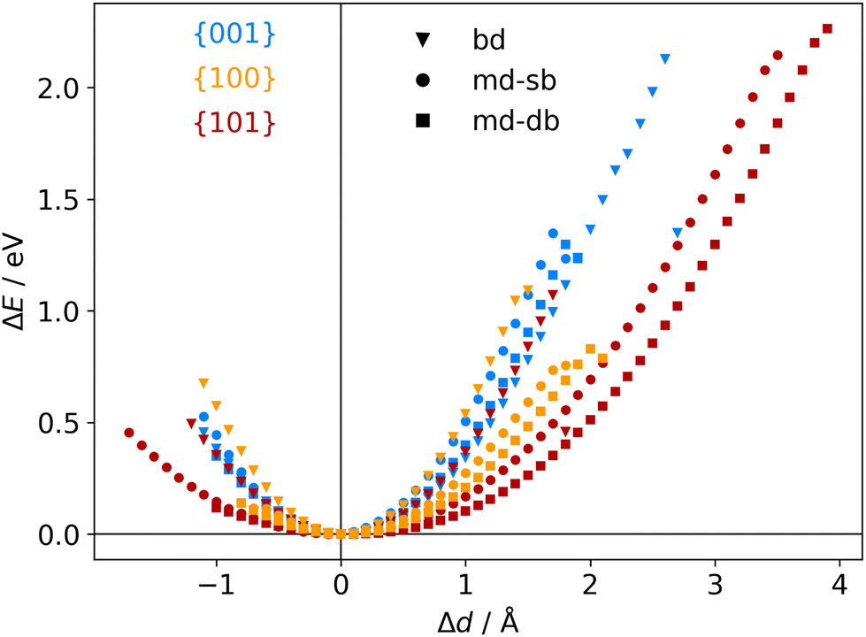 | ||
| Fig. 3 Calculated energy-displacement curves for different anatase-TiO2-carboxylic-acid interfaces, labelled by their facets (color legend shown in diagram) and connecting molecules (marker shape legend shown in diagram). | ||
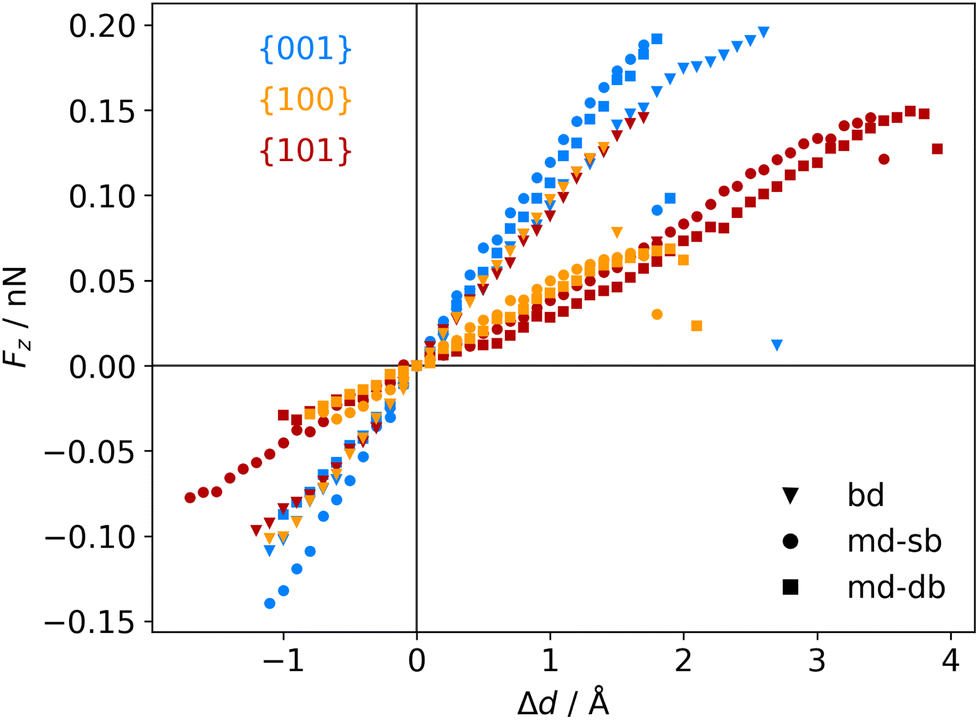 | ||
| Fig. 4 Calculated force-displacement curves for different anatase-TiO2-carboxylic-acid interfaces, labelled by their facets (color legend shown in diagram) and connecting molecules (marker shape legend shown in diagram). | ||
Intuitively, one would expect a correlation between the maximum energy in the tensile region and the binding energy of the carboxylic acid on the respective TiO2 surface. However, most of the interfaces fail at displacement energies much lower than their binding energies. This is related to the failure mechanisms, and to how the employed algorithm detects interface failure. A set of structures exemplifying the different failure modes that were observed in the calculations is shown in Fig. 5. The full set of initial and final (failed) interface structures can be found in the ESI,† and Table 1 lists the failure modes along with other calculated mechanical properties of the different interfaces.
 | ||
| Fig. 5 Illustration of the different failure modes encountered in the calculations applying tensile strain. Top to bottom: Detach failure mode in the {100}-md-sb interface, surface failure mode in the {001}-bd interface, and special failure mode in the {101}-bd interface. Color code: Ti – blue, O – red, C – black, H – green. | ||
 ), and elastic moduli (
 in GPa). Strains and elastic moduli are based on the interphase strain, as discussed in the main text. A two-sided 95% confidence interval resulting from the linear fit is given for the elastic moduli
| Facet | Binding mode | Failure mode | σ max/MPa |
|
|
|
|---|---|---|---|---|---|---|
| {101} | Bi-dentate (bd) | Special | 366.6 | 0.172 | 2.35(29) | 2.76(46) |
| Quasi-bd (qbd) | Surface | 366.4 | 0.364 | 0.78(49) | 1.27(73) | |
| qbd – double bond | Surface | 375.6 | 0.429 | 0.72(32) | 1.02(14) | |
| {100} | Bi-dentate (bd) | Surface | 346.7 | 0.137 | 2.92(19) | 3.03(22) |
| Quasi-bd (qbd) | Detach | 179.0 | 0.160 | 1.66(17) | 1.68(22) | |
| qbd – double bond | Detach | 185.3 | 0.193 | 1.22(25) | 1.03(23) | |
| {001} | Bi-dentate (bd) | Surface | 676.5 | 0.247 | 3.66(62) | 3.78(73) |
| Quasi-bd (qbd) | Surface | 650.6 | 0.145 | 5.54(46) | 5.68(45) | |
| qbd – double bond | Surface | 662.3 | 0.157 | 4.74(31) | 3.91(48) |
In the detachment mode, which is only observed for interfaces of the {100} facet with molecules bound in a mono-dentate fashion, the molecule simply detaches from the surface, resulting in a drop of the force that stops the algorithm. As can be seen from the example in the top panel of Fig. 5, the molecule is still relatively close to the surface after the breaking of the chemical bond. Hence, the low breaking energy compared to the calculated binding energies can be explained by the remaining physical binding to the surface. Further deformation would only require a low force, but would remove the molecule completely from the surface, thereby increasing the strain energy up to the binding energy.
Most of the interfaces studied in this work, however, break through a surface failure mode. As illustrated for the {001}-bd interface in the middle panel of Fig. 5, a Ti atom or even a whole unit of TiO2 is ripped from the surface in this failure mode. Therefore, not the binding energy of the molecule on the surface, but rather the cohesion within the surface will determine the binding energy of the interface in those cases. As shown in Table 1, the interface strengths for the surface failure mode are in the typical range for the tensile strength of bulk TiO2 ceramics,39 while they are much lower for the detachment mode. This further supports the view that due to the nanoconfinement and the strong binding to the surface, the organic phase is strengthened, making the oxide the weakest link in the interface. It also provides an explanation to why replacing the carboxylic acid anchoring group with a more strongly binding group (e.g. a phosphonic acid) does not necessarily improve the mechanical properties.8 Hence, the toughness and strength of nanocomposites can be optimized by balancing the binding strength with the strength of the particle phase.
The {001}-bd interface is described here in more detail as an example of a complex failure scenario involving different bonding configurations. The changes in the bond configuration are illustrated in Fig. 6 using the electron localisation function (ELF).40,41 The ELF is a measure of electron localisation. While a value of 0.5 corresponds to the localisation of the uniform electron gas, a value of 1 means perfect localisation. In Fig. 6, for example, the high ELF values between the carbon atoms in the acid molecule represents the covalent bonds in the backbone, while the electron localisation at the O and Ti atoms in the TiO2 slab without significant ELF values between the atoms indicates ionic bonding. The high ELF values around the acid oxygens show the covalent bond to the carbon atom as well the lone pairs of oxygen. In the initial unstrained interface configuration, the acid molecule binds to the TiO2 surface via two bonds between surface Ti atoms and acid O atoms, as well as a hydrogen bond formed by the dissociated acid hydrogen. However, the Ti–O bonds are not equivalent due to the nearby hydrogen bond and one is stretched by about 0.2 Å. According to the ELF, the electrons are localised at the Ti atoms and close to the acid O atoms, arguing against a covalent bond. It has to be noted here that in Fig. 6 the ELF isosurfaces seem to be touching or overlapping at the slab-molecule interface; however, this is only because of the 2D view and actually there is no overlap. According to a Bader charge analysis all Ti atoms are positively charged by about 2.2e, while all O atoms of the slab and molecules have a negative charge of about −1.1e +/−0.1e, where e is the elementary charge. This suggests an electrostatic interaction between the surface Ti and acid O atoms. The dissociated hydrogen adsorbed to the TiO2 surface holds a positive charge of about 0.65e leading to a charging of the surface and the carboxylate. Under tensile stress, the elongated Ti–O bond stretches further while the other bond maintains its length of about 2 Å until surface failure. At a displacement of 2.2 Å the elongated bond reaches a length of about 2.9 Å. At the next displacement step this bond breaks and the distance increases to about 3.6 Å. At the same time, the molecule reorients to shorten the length of the hydrogen bond. In the next few displacements this bond is stretched again until it breaks. At the same time the surface fails and a chelating bond geometry between the molecule and failed surface is formed, as shown in the middle panel of Fig. 5. The Bader charges are not significantly affected during the tensile test and thus no further charge transfer occurs. The general ELF characteristics and therefore the involved bonding types are also maintained; however, the bonding configuration and geometries are affected by the tensile stress. The different bond configurations give rise to changes in the mechanical response as reflected by the slope of the corresponding curve in Fig. 4.
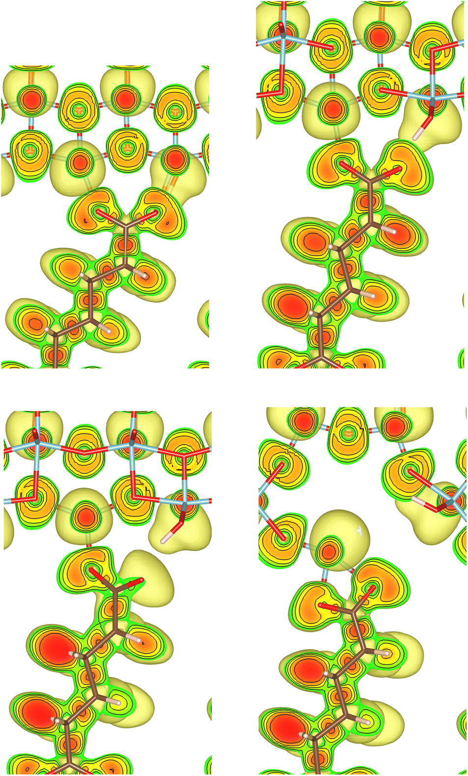 | ||
| Fig. 6 Illustration of the Electron Localization Function (ELF) for the {001}-bd interface. Isosurfaces of the ELF are shown starting from the value of 0.5 to 0.9 in 0.1 steps and coloured from green to red. The top right corner shows the initial unstrained configuration followed by the structures at the displacement steps 2.2 Å, 2.3 Å, and 2.7 Å during the tensile test. A section through the ELF parallel to the (100) plane is shown. Color code: Ti – blue, O – red, C – black, H – green. | ||
For comparison ELF plots for the {100}-md-sb interface are shown in the ESI.† This interface exhibits the detachment failure mode under tensile deformation, see top illustration in Fig. 5. The characteristics of the ELF are in general very similar to the previous case indicating the same bond types. During the tensile deformation mainly the linker molecule reorients and stretches to accommodate the stress until the molecule detaches from one surface and the distance to the surface grows as the system relaxes. The ELF is not significantly changing during the tensile test suggesting that the bonding nature is not affected.
Another interesting case is observed for the {101}-bd interface (cf.Fig. 5, bottom). Here, the force drops significantly due to a change in the binding mode from the initial bi-dentate binding to the weaker mono-dentate binding. This stops the algorithm, but does not destroy the interface. If deformed further, the interface would react similar to the properties calculated for the {101}-md-sb interface up to the final point of failure. Thereby, this interface can take up more strain energy than what the energy-displacement curve in Fig. 3 suggests. Furthermore, the change in binding mode may be reversible, thereby opening a pathway to annealing the nanocomposite after it suffered a significant amount of strain that caused a change of the binding mode and hence, a decrease of the interface's stiffness.
At this point it should be noted that the sandwich models in this study are limited by their size, which is constrained by the computational demand of the DFT calculations. Therefore, all failure modes break the whole interface at once, and we can not detect local failure modes that initiate a crack and leave the rest of the interface intact. Nevertheless, ab initio studies of the bonding states and of the mechanical reaction to strain, such as the one presented here, give valuable insights into the mechanisms that will also be relevant on larger scales. One way to bridge the length scales in future studies could be to train a machine-learned force field (MLFF) based on ab initio molecular dynamics (AIMD) calculations.42
Independent of the failure mode, we observe that only a few of the relaxed layers in the surfaces are deformed significantly during the mechanical loading. The deformation zone is roughly 4 Å to 8 Å thick on both sides, justifying a posteriori the choice of the number of relaxed layers in the interface model. Combing the deformation zones of both slabs with the interphase between the slabs gives a total deformation zone up to a factor of 3 thicker than the interphase alone.
In order to be able to include the calculated atomic scale mechanical properties into continuum mechanics models, and compare the results with data from experiments, it is necessary to convert the forces and displacements to stresses and strains, respectively. Converting the force to a stress (σzz) is straight forward in this uni-axial loading scenario, and can be simply achieved by dividing the force perpendicular to the interface (Fz) by the area of the surface unit cell A:
| σzz = Fz/A | (2) |
It has to be noted, that the density of molecules per unit area, of course, influences the mechanical response of the interface. Hence, the same number of molecules per unit cell was employed in all models irrespective of the binding mode in order to achieve comparability of the results. This results in a full occupation of all Ti binding sites for the bi-dentate binding mode, and an occupation of half of the Ti binding sites for the mono-dentate binding mode. As mentioned before, this also corresponds to the energetically most favourable configurations for larger carboxylic acids on TiO2 surfaces.15,19–25
The strain of the sandwich model in Fig. 2 is technically defined as
| εzz = Δd/D0, | (3) |
 | (4) |
 , that only depends on the linker molecules and their system specific geometry. The change of the strain from adding more fixed layers to the system is completely accounted for by the geometry factor
  . The interphase strain
  overestimates the real strain of the system, since the geometry factor is always smaller than one by definition, but enables a direct comparison of the different facets and binding modes. From an additional point of view, the interphase strain corresponds to a one-bulk-layer limit, i.e. taking the distance between the opposing surfaces in the ground state as a reference (see Fig. 2). This is the shortest possible reference length overestimating the actual strain in the interface, and therefore, underestimating the elastic modulus. For nanocomposites, one can identify d0 with the distance between two sheets of the material or the inter-particle distance considering a composite built from nanoparticles. D0 is associated with the nearest-neighbour distance measured between the centers of neighbouring sheets or particles. This approach enables a comparison of experimental results with the calculated results presented here.
The atomistic stress–strain diagrams of the different interfaces studied in this work are shown in Fig. 7, while the elastic moduli and maximum stresses derived from these diagrams are listed in Table 1. Clearly, the interfaces formed with the {001} facet exhibit the highest strength and stiffness, irrespective of the binding mode of the carboxylic acid. Furthermore, there is no significant difference between molecules containing a double bond in the backbone and the ones that do not. The bi-dentate binding mode leads to much stiffer interfaces with the {100} and {101} facets, and in the case of the {100} facet also to a higher strength. For the {001} facet, on the other hand, no clear preference for a binding mode is observed, with only slightly stiffer interfaces formed for a mono-dentate binding. Combining these pieces of information supports the hypothesis that the structure and the binding in the near-surface region dictates the mechanical properties of the interface.
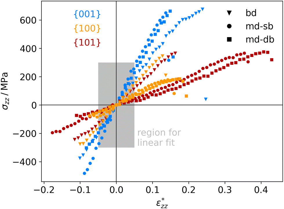 | ||
| Fig. 7 Calculated stress–strain curves for different anatase-TiO2-carboxylic-acid interfaces, labelled by their facets (color code shown in diagram) and connecting molecules (marker code shown in diagram). The region for determining the elastic moduli (see Table 1) is marked in grey. | ||
To the authors’ knowledge, there are currently no experiments that allow a direct comparison with the mechanical properties presented here, being calculated for idealised, perfectly flat interfaces. Nevertheless, membranes made from TiO2 nanoparticles with different shapes and linked by carboxylic acids exhibit a similar trend for the elastic moduli.18 In that study, membranes built from flat, platelet-shaped particles with a large percentage of {001} facets had the highest elastic moduli of around 7.2 GPa. In second place, membranes from rod-shaped particles dominated by {100} facets reach values around 5.2 GPa, followed by membranes from dot-shaped particles, which are thought to have mainly {101} facets and reach only 2.6 GPa (see ref. 18 for further information). However, the particles are not ordered well in that study, which will affect the mechanical properties. In supercrystalline nanocomposites, nanoparticles with organic ligand shells are well ordered on three dimensional lattices. Such composites can be built, e.g., from magnetite nanoparticles and carboxylic acids.8,43–45 For such materials we are expecting similar mechanical properties as for the TiO2-based systems in this work, since the linker molecules, the surface structures, and the interfacial strengths are similar.19,20,46,47 The tensile strengths of such nanocomposites were determined to lie between roughly 500 and 700 MPa.8 Those values can be readily compared to our results and they are in good agreement.
Strains and consequently elastic moduli are again more difficult to compare. In typical nanocomposites the inorganic part is much stiffer than the organic one. Thus, practically a rigid zone is given by the nanoparticle diameter minus a few atomic layers and is often in the tens of nm, while the deformation zone is only a few nm thick. A factor of 10 between both is often reasonable.8,45 This is consistent with the calculations presented in this work, where we find a deformation zone of only a few atomic layers. In the supercrystalline magnetite-carboxylic-acid composites mentioned before, the values of d0 and D0 can be associated with the inter-particle distance and the nearest-neighbour distance of the particles, respectively. This gives a structure factor d0/D0 of roughly 1/30 found in real materials.43 Of course, that is a very rough estimate and one should bear in mind that the real material is not a series of sheets and shows a more complex loading behavior and stress distribution. Still, the tensile strains of real nanocomposites are in the order of 0.5 to 1%,8 which compares reasonably to the results presented here considering a factor in the order of 30. The situation is similar for the Young's modulus which is in the order of 150 GPa in the experiments and compares well to the results here, particularly, for the (001) surface. Hence, despite of the drastic simplifications of the ab initio modelling approach, completely neglecting the micro-structure of the material, a qualitative prediction and comparison of mechanical properties of the different interfaces is possible with this approach.
4 Conclusions
In summary, we modelled the stress–strain curves of interfaces in nanocomposites made of anatase TiO2 nanoparticles and linker molecules with carboxylic acid anchoring groups. The models consist of periodic sandwich structures built from the dominant facets of the nanoparticles and the energetically most favorable binding modes (mono- and bi-dentate) of the carboxylic acids. Therefore, they represent the most relevant contributions to mechanical properties, such as the interface strength, strain at interface failure, and the elastic modulus. The mechanical response to tensile and compressive loading was calculated with DFT in the quasi-static limit, allowing all atoms in the interface to relax under the given constraint on the interface strain.Most of the interfaces studied here fail through a surface failure mode, where one unit of TiO2 is ripped out of the surface, and not through a simple debonding of the molecule, which is often assumed in the literature. Therefore, not only the binding energy of the molecule, but also the cohesion within the surface is an important parameter for the prediction and optimization of the mechanical properties of hybrid interfaces. A new mechanism is revealed, where the binding mode on the {101} facet changes under tensile load, releasing some of the interface stress. This finding may open a possible pathway to annealing the material.
The calculated elastic moduli agree qualitatively with experimental results for nanocomposite membranes made from faceted anatase TiO2 nanoparticles and carboxylic acid linker molecules as well as for supercrystalline nanocompsites made of Fe3O4 nanoparticles and carboxylic acid linker molecules. Therefore, it can be concluded that the model presented here is able to predict the effect of faceting on the mechanical properties of nanocomposites, which is a valuable feature for the computational optimization of this class of materials. Furthermore, integrating the results presented here in multi-scale models will allow to also understand the effect of microstructure on the overall mechanical properties. It would be interesting to study the response to shear strain with the same interface model in the future as well, in order to facilitate the inclusion in multi-scale models and to gain an even better understanding of the relevant processes on the atomic scale.
Author contributions
KS: Conceptualization, formal analysis, investigation, methodology, software, visualization, writing – original draft, writing – review and editing. GBVF: Conceptualization, formal analysis, funding acquisition, investigation, methodology, project administration, resources, supervision, writing – review and editing.Conflicts of interest
There are no conflicts to declare.Acknowledgements
The authors thank Ingo Scheider and Robert Meißner for valuable discussions about mechanical properties in multi-scale simulation models, as well as Clemens Schröter and Tobias Vossmeyer for their insights into measuring mechanical properties of nanocomposites, and Diletta Giuntini for her feedback on the manuscript. Funded by the Deutsche Forschungsgemeinschaft (DFG, German Research Foundation) – Project number 192346071 – SFB 986. K. S. also funded by the Deutsche Forschungsgemeinschaft (DFG, German Research Foundation) – Project number 506703280.References
- M. Eder, S. Amini and P. Fratzl, Science, 2018, 362, 543–547 CrossRef PubMed.
- L. H. He and M. V. Swain, J. Mech. Behav. Biomed. Mater., 2008, 1, 18–29 CrossRef PubMed.
- P. Stempflé, O. Pantalé, M. Rousseau, E. Lopez and X. Bourrat, Mater. Sci. Eng., C, 2010, 30, 715–721 CrossRef.
- E. V. Sturm (née Rosseeva) and H. Cölfen, Crystals, 2017, 7, 207 CrossRef.
- D. Giuntini, E. Torresani, K. T. Chan, M. Blankenburg, L. Saviot, B. Bor, B. Domènech, M. Shachar, M. Müller, E. A. Olevsky, J. E. Garay and G. A. Schneider, Nanoscale Adv., 2019, 1, 3139–3150 RSC.
- M. Li, I. Scheider, B. Bor, B. Domènech, G. A. Schneider and D. Giuntini, Compos. Sci. Technol., 2020, 108283 CrossRef CAS.
- A. Colak, J. Wei, I. Arfaoui and M.-P. Pileni, Phys. Chem. Chem. Phys., 2017, 19, 23887–23897 RSC.
- B. Bor, D. Giuntini, B. Domènech, A. Plunkett, M. Kampferbeck, T. Vossmeyer, H. Weller, I. Scheider and G. A. Schneider, Appl. Phys. Rev., 2021, 8, 031414 CAS.
- W. J. I. DeBenedetti, E. S. Skibinski, D. Jing, A. Song and M. A. Hines, J. Phys. Chem. C, 2018, 122, 4307–4314 CrossRef CAS.
- H. Park, A. May, L. Portilla, H. Dietrich, F. Münch, T. Rejek, M. Sarcletti, L. Banspach, D. Zahn and M. Halik, Nat. Sustain., 2020, 3, 129–135 CrossRef.
- W. Wu, Z. Wu, T. Yu, C. Jiang and W.-S. Kim, Sci. Technol. Adv. Mater., 2015, 16, 023501 CrossRef PubMed.
- D. Reyes-Coronado, G. Rodríguez-Gattorno, M. E. Espinosa-Pesqueira, C. Cab, R. d. Coss and G. Oskam, Nanotechnology, 2008, 19, 145605 CrossRef CAS PubMed.
- T. R. Gordon, M. Cargnello, T. Paik, F. Mangolini, R. T. Weber, P. Fornasiero and C. B. Murray, J. Am. Chem. Soc., 2012, 134, 6751–6761 CrossRef CAS PubMed.
- L. Wu, B. X. Yang, X. H. Yang, Z. G. Chen, Z. Li, H. J. Zhao, X. Q. Gong and H. G. Yang, CrystEngComm, 2013, 15, 3252–3255 RSC.
- K. Sellschopp, W. Heckel, J. Gäding, C. J. Schröter, A. Hensel, T. Vossmeyer, H. Weller, S. Müller and G. B. Vonbun-Feldbauer, J. Chem. Phys., 2020, 152, 064702 CrossRef CAS PubMed.
- H. G. Yang, C. H. Sun, S. Z. Qiao, J. Zou, G. Liu, S. C. Smith, H. M. Cheng and G. Q. Lu, Nature, 2008, 453, 638–641 CrossRef CAS PubMed.
- A. Fujishima, X. Zhang and D. A. Tryk, Surf. Sci. Rep., 2008, 63, 515–582 CrossRef CAS.
- A. Hensel, C. J. Schröter, H. Schlicke, N. Schulz, S. Riekeberg, H. K. Trieu, A. Stierle, H. Noei, H. Weller and T. Vossmeyer, Nanomaterials, 2019, 9, 1230 CrossRef CAS PubMed.
- W. Heckel, B. A. M. Elsner, C. Schulz and S. Müller, J. Phys. Chem. C, 2014, 118, 10771–10779 CrossRef CAS.
- W. Heckel, T. Würger, S. Müller and G. Feldbauer, J. Phys. Chem. C, 2017, 121, 17207–17214 CrossRef CAS.
- A. Vittadini, A. Selloni, F. P. Rotzinger and M. Grätzel, J. Phys. Chem. B, 2000, 104, 1300–1306 CrossRef CAS.
- X.-Q. Gong, A. Selloni and A. Vittadini, J. Phys. Chem. B, 2006, 110, 2804–2811 CrossRef CAS PubMed.
- W.-K. Li, X.-Q. Gong, G. Lu and A. Selloni, J. Phys. Chem. C, 2008, 112, 6594–6596 CrossRef CAS.
- D. C. Grinter, M. Nicotra and G. Thornton, J. Phys. Chem. C, 2012, 116, 11643–11651 CrossRef CAS.
- G. Tabacchi, M. Fabbiani, L. Mino, G. Martra and E. Fois, Angew. Chem., Int. Ed., 2019, 58, 12431–12434 CrossRef CAS PubMed.
- M. K. Beyer, J. Chem. Phys., 2000, 112, 7307–7312 CrossRef CAS.
- T. Stauch and A. Dreuw, Chem. Rev., 2016, 116, 14137–14180 CrossRef CAS PubMed.
- G. Feldbauer, M. Wolloch, P. O. Bedolla, P. Mohn, J. Redinger and A. Vernes, Phys. Rev. B: Condens. Matter Mater. Phys., 2015, 91, 165413 CrossRef.
- G. Kresse and J. Hafner, Phys. Rev. B: Condens. Matter Mater. Phys., 1993, 47, 558–561 CrossRef CAS PubMed.
- G. Kresse and J. Hafner, Phys. Rev. B: Condens. Matter Mater. Phys., 1994, 49, 14251–14269 CrossRef CAS PubMed.
- G. Kresse and J. Furthmüller, Phys. Rev. B: Condens. Matter Mater. Phys., 1996, 54, 11169–11186 CrossRef CAS PubMed.
- G. Kresse and J. Furthmüller, Comput. Mater. Sci., 1996, 6, 15–50 CrossRef CAS.
- P. E. Blöchl, Phys. Rev. B: Condens. Matter Mater. Phys., 1994, 50, 17953–17979 CrossRef PubMed.
- J. P. Perdew, K. Burke and M. Ernzerhof, Phys. Rev. Lett., 1996, 77, 3865–3868 CrossRef CAS PubMed.
- S. Grimme, J. Antony, S. Ehrlich and H. Krieg, J. Chem. Phys., 2010, 132, 154104 CrossRef PubMed.
- G. Henkelman, A. Arnaldsson and H. Jónsson, Comput. Mater. Sci., 2006, 36, 354–360 CrossRef.
- E. Sanville, S. D. Kenny, R. Smith and G. Henkelman, J. Comput. Chem., 2007, 28, 899–908 CrossRef CAS PubMed.
- W. Tang, E. Sanville and G. Henkelman, J. Phys.: Condens. Matter, 2009, 21, 084204 CrossRef CAS PubMed.
- M. A. Meyers and K. K. Chawla, Mechanical behavior of materials, Cambridge University Press, Cambridge, New York, 2nd edn, 2009 Search PubMed.
- A. Becke and K. Edgecombe, J. Chem. Phys., 1990, 92, 5397–5403 CrossRef CAS.
- B. Silvi and A. Savin, Nature, 1994, 371, 683–686 CrossRef CAS.
- O. T. Unke, S. Chmiela, H. E. Sauceda, M. Gastegger, I. Poltavsky, K. T. Schütt, A. Tkatchenko and K.-R. Müller, Chem. Rev., 2021, 121, 10142–10186 CrossRef CAS PubMed.
- D. Giuntini, A. Davydok, M. Blankenburg, B. Domènech, B. Bor, M. Li, I. Scheider, C. Krywka, M. Müller and G. A. Schneider, Nano Lett., 2021, 21, 2891–2897 CrossRef CAS PubMed.
- B. Domènech, M. Kampferbeck, E. Larsson, T. Krekeler, B. Bor, D. Giuntini, M. Blankenburg, M. Ritter, M. Müller, T. Vossmeyer, H. Weller and G. A. Schneider, Sci. Rep., 2019, 9, 1–11 CrossRef PubMed.
- A. Plunkett, M. Kampferbeck, B. Bor, U. Sazama, T. Krekeler, L. Bekaert, H. Noei, D. Giuntini, M. Fröba, A. Stierle, H. Weller, T. Vossmeyer, G. A. Schneider and B. Domènech, ACS Nano, 2022, 16, 11692–11707 CrossRef CAS PubMed.
- B. Arndt, K. Sellschopp, M. Creutzburg, E. Grånäs, K. Krausert, V. Vonk, S. Müller, H. Noei, G. B. V. Feldbauer and A. Stierle, Commun. Chem., 2019, 2, 1–8 CrossRef CAS.
- M. Creutzburg, K. Sellschopp, S. Tober, E. Grånäs, V. Vonk, W. Mayr-Schmölzer, S. Müller, H. Noei, G. B. Vonbun-Feldbauer and A. Stierle, J. Phys. Chem. Lett., 2021, 12, 3847–3852 CrossRef CAS PubMed.
Footnotes |
| † Electronic supplementary information (ESI) available: Additional visualizations of all nine different interface structures in their initial (relaxed) and final (failed) state. Stress-strain curves and mechanical properties from calculations using the D3 van-der-Waals correction. Illustrations of the Electron Localization Function for the {100}-md-sb interface. See DOI: https://doi.org/10.1039/d3nr01045g |
| ‡ Present address: Institute of Hydrogen Technology, Helmholtz-Zentrum Hereon, Max-Planck-Str. 1, 21502 Geesthacht, Schleswig-Holstein, Germany. E-mail: kai.sellschopp@hereon.de. |
| This journal is © The Royal Society of Chemistry 2023 |